NOTE: These instructions are to be used along with the installationinstructions for ACRYLIC BATHTUBS.
WARNING - When using electrical products, basic precautionsshould always be followed, including the following:
1. RISK OF ELECTRICAL SHOCK.
Connect only to a circuit protected by a ground faultcircuit interrupter, (GFCI).
2. Grounding is required. An equipment groundingterminal is provided in the field wiring compartment. Toreduce the risk of electric shock, this terminal must beconnected to the grounding means provided in theelectric supply panel with a conductor equivalent in sizeto the circuit conductors supplying the equipment.
3. INSTALL THIS UNIT IN ACCORDANCE WITH THECANADIAN ELECTRICAL CODE, PART 1 OR THEAPPROPRIATE CODE IN OTHER COUNTRIES.
4. INSTALLTO PERMITACCESS FOR SERVICING.
5. Provide adequate ventilation for the motor to preventnuisance trips of the thermal overload protection.
Important:AllAcrylicAir Massage baths receive a thorough watertest and are carefully inspected and packed for shipment. Youshould check your unit for any problems. Contact your dealerbefore installation.
Protect the bathtub and fittings from dirt and damage by leavingthe polyethylene protective film in place until installation andother related construction are complete.
DANGER:
INSTALLATION NOTES
Caution: Do not lift an air massage bath or whirlpool by itsplumbing. Handle it by the bath shell only.
Access for servicing the Blower/Pump and Controls of the airmassage bath must be provided (Refer to specification drawingsfor location). DO NOT remove or relocate the blower or pumpfrom its factory-installed position. This position ensures properpriming, drainage, and performance of the air massage orcombination system.
Relocating the blower or pump will void the warranty.
NOTE:
MODELS WITH INTEGRAL APRON
The unions for the piping at the pump on thecombination units are only to be hand tightened. Check byhand that they have not loosened during shipping.
Air massage baths with an integral apron have a removablepanel in the apron for access to the blower and pump.
Depending on the design of the whirlpool the panel isfastened to the apron by either of the following:
Strips of interlocking fabric (velcro) along the topwith plastic clips on the bottom (Figure 1).
Screws (Figure 2).
In either case, to remove panel follow instructions below:
Panel with strips of interlocking fabric: gently pull the panelaway starting from the top.
To replace the panel, position the removable panel ontolower flange and press into place against the velcro pads.
!
!
Removable Centre Panel
1
1 2 3
REMOVABLEPANEL
VELCRO
CLIP
APRON FRAME
Figure 1 -
INSTALLATION AND OPERATING INSTRUCTIONSREAD ALL INSTRUCTIONS CAREFULLY BEFORE STARTING THE INSTALLATION OF YOUR
AIR MASSAGE / COMBINATION BATH.
PLEASE RECORD THE SERIAL NUMBER______ OF YOUR AIR MASSAGE BATH AND SAVE THIS MANUALFOR FUTURE REFERENCE.
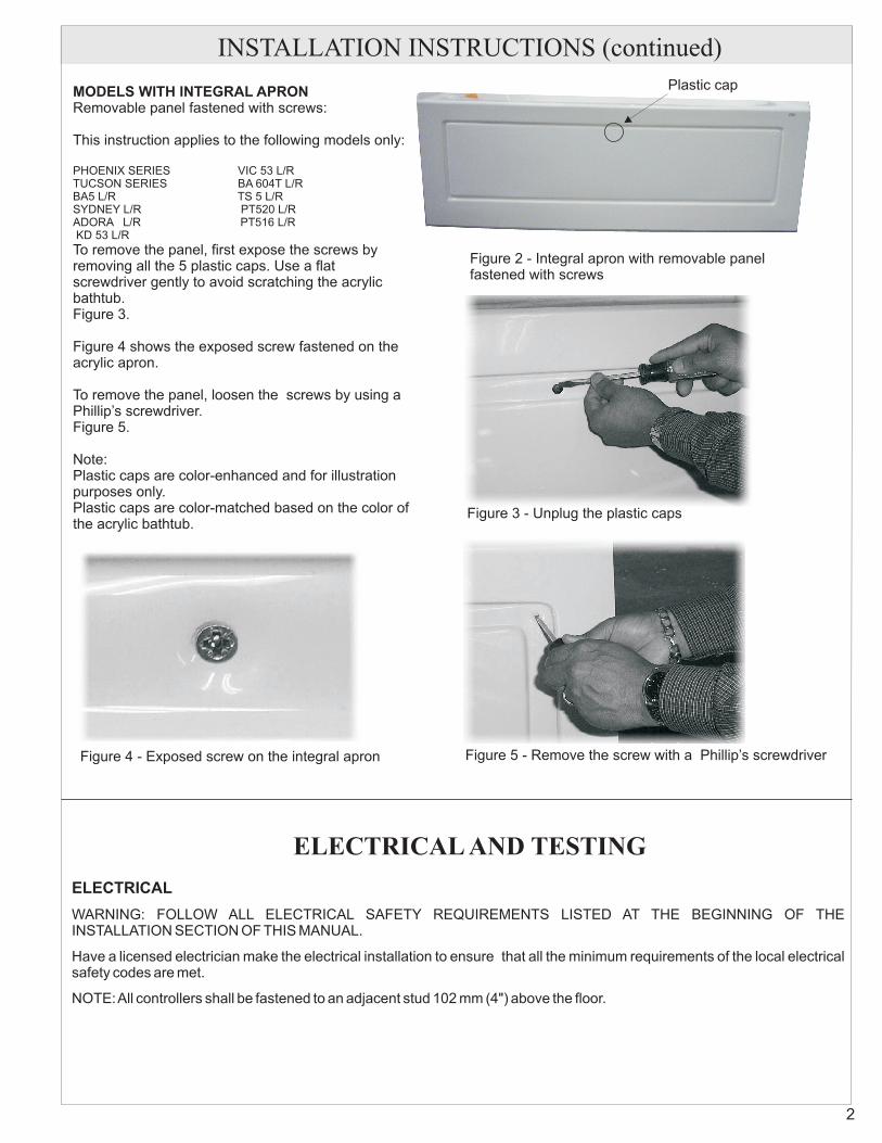
MODELS WITH INTEGRAL APRONRemovable panel fastened with screws:
This instruction applies to the following models only:
To remove the panel, first expose the screws byremoving all the 5 plastic caps. Use a flatscrewdriver gently to avoid scratching the acrylicbathtub.Figure 3.
Figure 4 shows the exposed screw fastened on theacrylic apron.
To remove the panel, loosen the screws by using aPhillip’s screwdriver.Figure 5.
Note:Plastic caps are color-enhanced and for illustrationpurposes only.Plastic caps are color-matched based on the color ofthe acrylic bathtub.
PHOENIX SERIES VIC 53 L/RTUCSON SERIES BA 604T L/RBA5 L/R TS 5 L/RSYDNEY L/R PT520 L/RADORA L/R PT516 L/RKD 53 L/R
Figure 2 - Integral apron with removable panelfastened with screws
Figure 3 - Unplug the plastic caps
Figure 4 - Exposed screw on the integral apron Figure 5 - Remove the screw with a Phillip’s screwdriver
INSTALLATION INSTRUCTIONS (continued)
ELECTRICAL AND TESTING
ELECTRICAL
WARNING: FOLLOW ALL ELECTRICAL SAFETY REQUIREMENTS LISTED AT THE BEGINNING OF THEINSTALLATION SECTION OF THIS MANUAL.
Have a licensed electrician make the electrical installation to ensure that all the minimum requirements of the local electricalsafety codes are met.
NOTE:All controllers shall be fastened to an adjacent stud 102 mm (4") above the floor.
2
Plastic cap
ELECTRICAL CONNECTIONS
Air Massage Air Massage / Whirlpool Combination
The installation must conform to the local electrical safetycodes. The following are general requirements only, theydo not cover all details or all situations.
The standard requirement is a separate 15A, 115V circuitprotected by a ClassA GFCI rated for 15A.
The cable from the service box is to be 2 wires plus aground. # 14 conductor is satisfactory for distances up to100 ft. (30 m).
For air massage, electrical connection is a standard classAGFCI - NEMAreceptacle.
Some local codes may require a disconnect switch. Thiscan be installed in the wall or near the motor in the servicecompartment.
If installed in the wall it must be at least 1.5 m (5 ft.) awayfrom the tub so that a person in the tub cannot reach it.If installed in the service compartment it should bemounted to a stud and not directly under tub.
The switch may be a standard wall switch as long as theampere rating is at least as great as the ampereprotection rating noted above.
The air massage blower and the whirlpool pump eachrequire a 15A, 115V circuit, that is, 2 separate lines fromthe service box with ClassA GFCI protection.
The cable from the service box is to be 14/2 wire which issatisfactory for distances up to 100 ft. (30 m).
If the local codes require a disconnect switch it must be aduplex switch installed in the service compartmentmounted to a stud and not directly to the tub.
The deck mounted touch-pad control on the Air Massageand Combination model is connected to two pin plugsmade at the factory. Check underneath the deck that thepin plugs are connected accordingly.
ELECTRONIC CONTROL, AIR MASSAGE ANDCOMBINATION
3
INSTALLATION INSTRUCTIONS (continued)
B
BWG
BW
G
BWG
110V, 15 A FROMSERVICE PANEL
B2 - 110V POWER SUPPLY1- BLACK1- WHITE (NEUTRAL)1 - GREEN (GROUND)
B1 - 110V POWER SUPPLY1- BLACK1- WHITE (NEUTRAL)1 - GREEN (GROUND)
B1 - 110V POWER SUPPLY1- BLACK1- WHITE (NEUTRAL)1 - GREEN (GROUND)
B2 - 110V POWER SUPPLY1- BLACK1- WHITE (NEUTRAL)1 - GREEN (GROUND)
CONTROLBOX(JET AIR)
12
RTM
on off
off
on
off
on
BLOWER Figure 6 - Air Massage/WhirlpoolCombination Connections
OPERATING INSTRUCTIONSIMPORTANT SAFETY INSTRUCTIONSREADAND FOLLOWALL INSTRUCTIONSSAVE THESE INSTRUCTIONS
1. WARNING: RISK OF ACCIDENTAL INJURY OR DROWNING; CHILDREN SHOULD NOT USE MASSAGEBATHTUB WITHOUTADULT SUPERVISION;
2. WARNING: RISK OF ACCIDENTAL INJURY OR DROWNING; DO NOT USE WHIRLPOOL BATHTUB UNLESSALLSUCTION GUARDSARE INSTALLED TO PREVENT BODYAND HAIR ENTRAPMENT;
3. WARNING: TOAVOID INJURY, EXERCISE CARE WHEN ENTERING OR EXITING THE MASSAGE BATHTUB;4. WARNING: RISK OF ELECTRIC SHOCK; DO NOT PERMIT ELECTRIC APPLIANCES ( SUCH AS A HAIR
DRYER, LAMP, TELEPHONE, RADIO OR TELEVISION) WITHIN 1.5 m (5 ft.) OF THIS MASSAGE BATHTUB;5. CAUTION: TEST THE GROUND FAULT CIRCUIT INTERRUPTER PROTECTING THIS APPLIANCE
PERIODICALLY INACCORDANCE WITH THE MANUFACTURER’S INSTRUCTIONS;6. WARNING: RISK OF HYPERTHERMIAAND POSSIBLE DROWNING: WATER TEMPERATURE IN EXCESS OF
38º C (100º F) MAY BE INJURIOUS TO YOUR HEALTH. CHECKANDADJUST WATER TEMPERATURE BEFOREUSE.
Your physiological response to a hot air massage or whirlpool bath depends on your age, health and medical history. Initially,stay in the bath for a short time only until you learn your tolerance for hot water. If you develop a headache or become dizzy ornauseous, get out at once and cool off under a shower. Get medical help if symptoms persist.
Consult your doctor before you use the air massage or whirlpool for physical therapy of an injury or disorder. Don’t take an airmassage or whirlpool bath without your doctor’s consent if you are ill or pregnant, or if you suffer from high blood pressure,heart disease, or other health problems. Never take an air massage or whirlpool bath while under the influence of medication,drugs, or alcohol.
DO NOT RUN THE WHIRLPOOLPUMP UNLESS THE BATH IS FILLED WITH WATER TOA LEVELOF 2” (50 mm)ABOVE THE WHIRLPOOL FITTINGS.
Use only small amount of soap or other bath preparation in whirlpool baths, otherwise excessive foaming may occur.
The Air Massage andAir Massage/ Whirlpool Combinations have electronic touch pad controls.
There is a heating element within the blower that heats the air in the reservoir to 40°C (104°F), to prevent the water fromcooling too fast.
NOTE: 20 minutes after the blower is shut off automatically or by the on/off control, the blower will come on again for 30seconds to dry the air jets.
FOLLOW ALL SAFETY INSTRUCTIONS IN THIS MANUAL
SAFE USE OFANAIR MASSAGE OR WHIRLPOOL
OPERATING CONTROLS
It will not, under any circumstances, reheat or maintain the temperature of the bath water.
If the tub has not been drained at the time it will be necessary to run the blower manually for 30 seconds to dry thejets after the tub is drained.
WARNING
SUCTION
DO NOT BLOCK SUCTION INLET SCREEN ON WHIRLPOOLBATHS.
Water is circulated back to the pump from this location. Should the inlet screen become blocked in any way the safety suction
will engage and the pump will start cavitating.
The pump will immediately shut down stopping the flow, thus releasing whatever is blocking the screen.
When the screen is free of blockage, the pump will automatically start up and the system is back to normal.
Under no circumstance is the pump to be used without the screen on the suction return.
4
OPERATING INSTRUCTIONS (continued)
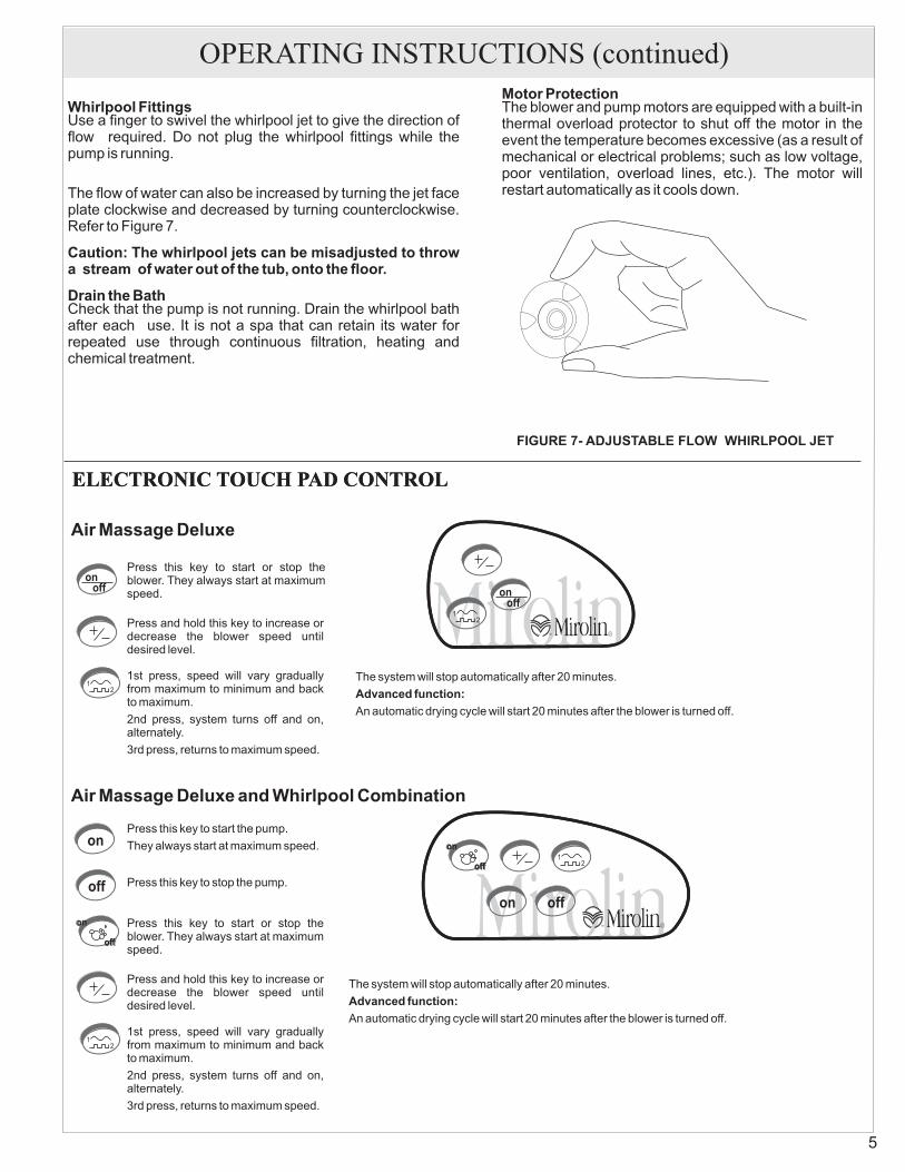
Whirlpool Fittings
Caution: The whirlpool jets can be misadjusted to throwa stream of water out of the tub, onto the floor.
Drain the Bath
Motor Protection
Use a finger to swivel the whirlpool jet to give the direction offlow required. Do not plug the whirlpool fittings while thepump is running.
The flow of water can also be increased by turning the jet faceplate clockwise and decreased by turning counterclockwise.Refer to Figure 7.
Check that the pump is not running. Drain the whirlpool bathafter each use. It is not a spa that can retain its water forrepeated use through continuous filtration, heating andchemical treatment.
The blower and pump motors are equipped with a built-inthermal overload protector to shut off the motor in theevent the temperature becomes excessive (as a result ofmechanical or electrical problems; such as low voltage,poor ventilation, overload lines, etc.). The motor willrestart automatically as it cools down.
ELECTRONIC TOUCH PAD CONTROL
Air Massage Deluxe
12
RTM
onoff
12
RTM
on off
off
on
off
on
ELECTRONIC TOUCH PAD CONTROL
12
onoff
Press this key to start or stop theblower. They always start at maximumspeed.
Press and hold this key to increase ordecrease the blower speed untildesired level.
1st press, speed will vary graduallyfrom maximum to minimum and backto maximum.
2nd press, system turns off and on,alternately.
3rd press, returns to maximum speed.
The system will stop automatically after 20 minutes.
An automatic drying cycle will start 20 minutes after the blower is turned off.
Advanced function:
Air Massage Deluxe and Whirlpool Combination
12
Press this key to start or stop theblower. They always start at maximumspeed.
Press and hold this key to increase ordecrease the blower speed untildesired level.
1st press, speed will vary graduallyfrom maximum to minimum and backto maximum.
2nd press, system turns off and on,alternately.
3rd press, returns to maximum speed.
The system will stop automatically after 20 minutes.
An automatic drying cycle will start 20 minutes after the blower is turned off.
Advanced function:
Press this key to stop the pump.
off
on
off
on
on
off
Press this key to start the pump.
They always start at maximum speed.
5
FIGURE 7- ADJUSTABLE FLOW WHIRLPOOL JET
OPERATING INSTRUCTIONS (continued)
IN-LINE BATH HEATER (Optional)
INTRODUCTION
Your AquaHeat Whirlpool Bath Heater utilizes “SmartTechnology” to offer you years of bathing pleasure. Theadvanced electronic design provides trouble free operationand precise control of water temperature.
There are no adjustments necessary, after the whirlpool isfilled with hot water the advanced AquaHeat Whirlpool BathHeater will maintain 104°F water temperature. To cool thewater simply add cold water as desired.
The whirlpool must be running for the Heater tofunction - It is controlled by a vacuum switch.
In the event the water temperature exceeds 114°F the heaterwill automatically shut-off. To reset, wait until the watertemperature drops below 104°F, then remove power fromthe heater by resetting the circuit breaker at the mainelectrical panel. If the High-Limit trips frequently, contact aqualified service technician.
NOTE:
High Limit ProtectionSpecifications:
1.5 kW “Inline”
"
"
115 Volt, 20AmpVacuum switch
B - BLACKG - GREENW - WHITE
B
WG
Vacuum Switch
WARNING
DANGER: RISK OF ELECTRIC SHOCK.
Grounding is required. Make certain the Heaterand Pump are properly grounded and the pumpis BONDED as required.
CAUTION
In the event the pump is not running or if there is notsufficient flow, the heater will not turn ON. To correct contacta qualified service technician.
- when using electrical products, basicprecautions should always be followed including thefollowing:
Connectonly to a circuit protected by a ground fault circuitinterrupter, (GFCI).Use copper conductors only.
The heater must be installed by a qualifiedelectrician in accordance with the NationalElectrical Code and any local codes.
Before operating the pump/heater, test the GFCI bypressing the “TEST” button, the pump and heater shouldnot operate. To resume operation press the “RESET”
button. If the GFCI fails to operate as described above,there is ground current flowing, DO NOT operate thepump/heater until this condition is corrected.
WARNING - When using this unit, basic precautionsshould always be followed, including the following:
1.2. - To reduce the risk of drowning , do notpermit children to use the whirlpool bath unless they aresupervised by an adult at all times.3. Use this heater for its intended use as described in thisManual. Do not alter this heater or electrical shock mayoccur.4. Do not operate the Whirlpool bath or this heater withsuction covers removed, make certain the suction coversare properly installed before use.5. The heater must be connected to a supply circuit that isprotected by a ground fault circuit interrupter, (GFCI). TheGFCI should be provided by the installer and should betested on a routine basis.
To Test the GFCI press the “TEST” button, the pump andheater should NOT operate. Press the “RESET” buttonand the pump and heater should resume operation. If theGFCI fails to operate in this manner, there is a groundcurrent flowing, indicating the possibility of an electricalshock. DO NOT use the pump and heater. Have theproblem corrected by a qualified electrician before using.
6. Prolonged immersion in hot water may inducehyperthermia. The causes, symptoms, and effects ofhyperthermia may be described as follows:
Hyperthermia occurs when the internal temperature of thebody reaches a level several degrees above normal bodytemperature of 98.6°F. The symptoms of hyperthermiainclude:a)An increase in the internal temperature of the bodyb) Dizzinessc) FaintingThe effects of hyperthermia include:a) Failure to perceive heatb) Failure to recognize the need to exit the bathc) Unawareness of impending hazardd) Fetal damage in pregnant womene) Physical inability to exit the bathf) Unconsciousness resulting in the danger of drowning
- Use of alcohol, drugs or medication cangreatly increase the risk of fatal hyperthermia.
7. To avoid potential damage: pregnant or possiblypregnant women should consult a physician before usingthe whirlpool. Water temperature in excess off 100°F isnot recommended.
8. The bath water temperature should not exceed 104°F.Lower temperatures are recommended for extended use(10-15 minutes) and are definitely recommended foryounger children.
READ AND FOLLOW ALL INSTRUCTIONS.DANGER
WARNING
Air Massage
Whirlpool Suction Fittings
The 30 second drying cycle after the tub is drained is important and is automatic after the air massage.
If the tub was used as a regular bath or the combination model was used only as a whirlpool, the air massage must be turnedon manually for 30 seconds after the tub is emptied.
On the combination whirlpool system, the suction screen is the one shown in Figure 8. Should the fitting require cleaning,remove the screw from the suction cover screen. Pull the cover off and remove any lint or other material. When replacing thecover, make sure that the screw registers. Put the screw back in place and tighten to ensure there is no gap between the tubwall and suction cover.
Figure 8-SUCTIONRETURNFITTING
MAINTENANCE INSTRUCTIONS
7
SUCTION WALL FITTING
SUCTION COVER SCREEN
Clean and Purge
Warning!
Restoring Surface Gloss
Minor Repairs to Surface
Special Finishes on Fittings
The internal piping of your whirlpool must becleaned regularly in order to reduce build up of dirt, scumand the like. This must be done even if you only use the tubfor bathing or soaking and you do not use the jets. Use thefollowing clean and purge procedure every week, ifthe tub is used daily, or third use, if the use isintermittent or occasional.
With the tub filled with bathing temperature waterto above the level of the jets, add 1 cup ofElectrasol Lemon Scented Gel - AdvancedCleaning Power dishwashing detergent. To savewater, you can add the detergent to the tub afteruse, before draining.Run the pump and jets for 10 minutes. Drain thetub.Refill the tub with fresh warm water to a levelabove the jets.Run the pump and jets for 5 minutes.Drain the tub.
We recommend the periodic use of Mirogloss Acrylicand Fiberglass polish to preserve the appearance of yourbath. Mirogloss Acrylic and Fiberglass polish isavailable from your dealer.
Restore surface gloss by applying a very fine rubbingcompound and polishing the surface by hand or with apower buffer. Finish with an application of Mirogloss or agood quality automotive wax.
Remove minor scratches and scuffs as follows. First, wetsand the area with 600 grit wet sandpaper until the surfaceis smooth. Then, restore the gloss as described underRESTORING SURFACE GLOSS.
DO NOT USE powders, pads, or liquids that containabrasives. Many household cleansers, includingdetergents for automatic dishwashers, are abrasive, andwould damage the plated or coloured surfaces as well asthe finish of the acrylic bath.
at leastevery
•
•
•
•
•
®
®
®
Acrylic Surface
The acrylic sheet which forms the surface of your bathtubprovides one of the most durable surfaces found in themodern bathroom. Keep it bright and smooth with mildliquid household detergent, soap and water, or foaming
cleansers, NEVER USE aromatic solvents, abrasivecleaners, scouring compounds or pads, strong liquidcleansers, or other material that could damage or dull thesurface of the bath.
MAINTENANCE INSTRUCTIONS (continued)
TROUBLESHOOTINGBlower fails to operate:
Motor runs, but no air comes through the jets:
Air outlets of jet heads are obstructed:
Blowing air seems to be cool.
1. Verify that electronic touch control is connectedproperly.
2. Check electric power supply. Reset circuitbreaker or replace fuse if necessary.
4. If the system has been functioning for sometime, itis possible that the thermal protection has shut offthe motor. Switch off the system and wait for atleast 30 minutes before using it again.
1. Verify that the main air hose from the manifold toblower is properly connected. If necessary,reconnect and tighten clamps.
1. If the air outlets of a jet head are obstructed bysoap or other residues, fill tub with warm water,brush the jets gently with an old toothbrush, thenswitch system ON and OFF several times.
1. If your tub is installed against two outside walls, itis recommended to ensure adequate insulationfor these outside walls to minimize heat loss.
2. Upon initial use when the bath water is very hotthe initial burst of air through the lines will feel cool
because the air is at lower temperature than thebath water. The blower takes 5 minutes to reachoptimum operating temperature.
3. Skin sensitive people might experience the so-called “cold air effect” which is caused by thesensation of air bubbles running along the wetskin and providing the bather with a shiveringsensation. Just move your body slightly awayfrom the closest jet to stop the sensation of coldair. (NOTE: Even if the out coming air would be hotenough to burn the skin, this shivering effectwould still persist.)
NOTE:
The drying cycle:
The air heater is not designed to heat the bathwater, just to preheat the incoming air to bodytemperature 36-37° C (97-98° F).After 5 min. Of run time the air leaves the blowerreservoir at 40°C (104°F) and by the time itreaches the jet orifice it’s at 36-37°C (97-98°F).
1. The electronic control of your system isprogrammed so that 20 minutes after the systemis shut OFF a drying cycle comes onautomatically. This drying cycle blows hot air for30 seconds through the piping in order to dry thejet heads. Do not interrupt the drying cycle. If thecycle comes on and is stopped during the cycle,the program will start at the beginning and a newdrying cycle will come on 20 minutes later.
8
A
B
C
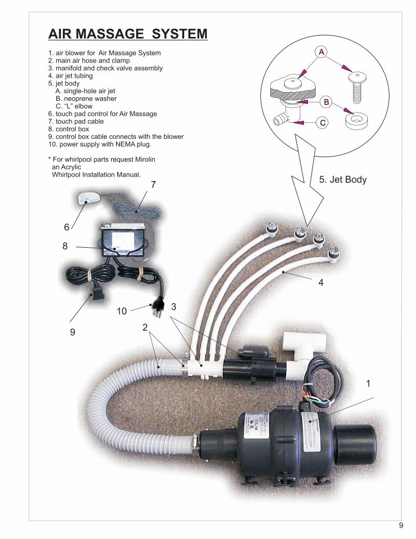
AIR MASSAGE SYSTEM1. air blower for Air Massage System2. main air hose and clamp3. manifold and check valve assembly4. air jet tubing5. jet body
A. single-hole air jetB. neoprene washerC. “L” elbow
6. touch pad control for Air Massage7. touch pad cable8. control box9. control box cable connects with the blower10. power supply with NEMA plug.
* For whirlpool parts request Mirolinan AcrylicWhirlpool Installation Manual.
5. Jet Body
9
1
4
2
3
7
6
8
9
10
A
B
C
1. air blower for both Air Massage and Combination units2. main air hose and clamps3. manifold and check valve assembly4. air jet tubing5. jet body
A. single-hole air jetB. neoprene washerC. “L” elbow
6. touch pad control for Air Massage and WhirlpoolCombination7. touch pad cable (Air Massage)
5. Jet Body
4
2
3
AIR MASSAGE SYSTEM &WHIRLPOOL COMBINATION
8. control box (Air Massage)9. control box cable (connects with the blower)10. power supply (input)11. touch pad cable (Whirlpool System)12. control box (Whirlpool System)13. control box cable connects with the whirlpool pump/motor14. power supply (input)15. cable - connects control box with the whirlpool pump/motor
* For whirlpool parts request Mirolin an AcrylicWhirlpool Installation Manual.
9 87
13
10
11
124 Port Manifold
PART IDENTIFICATIONREFERENCE WHIRLPOOL SYSTEM DRAWING
NOTE: WHEN ORDERING:**Specify colour or finish
**
**
KEY DESCRIPTION1.0 Electrical motor & pump1.1 Pump union2.0 1-1/2” (38 mm) Suction pipe3.0 1-1/2” (38 mm) Pressure union4.1 Suction elbow 90 deg. - 1 ½” (38 mm)4.2 Suction drain body (Suction flange)4.3 Drain face plate ( Suction cover screen)4.4 Screw5.0 Air line flex pipe - 3/8” (10 mm)6.1 Jet body6.2 Wall fitting6.3 Face plate7.1 Foot jet body7.2 Foot jet gasket7.3 Foot jet wall fitting7.4 Foot jet face plate
KEY DESCRIPTION8.0 1-1/2” (38mm) Breaking Union9.1 Air switch on/off for pump9.2 Air switch gasket9.3 Air switch PVC nut10.0 Air check valve11.0 Clamp12.0 Air manifold13.0 T connector14.0 Water line flex pipe - 1” (25 mm)15.0 Suction flex pipe - (3/8” 10mm)16.0 V - Fitting17.0 Back Jet Assembly
TYPICAL WHIRLPOOL SYSTEM WITHOUT BACK JETS
5
7.1
7.2
7.3
7.4
9.1
9.2
9.3
4.1
4.2
4.3
4.4
1
2
36.1
6.2
6.3
11
10
12
13
814
15
1.1
17
17.317.2
17.1
Back JetAssembly
V - Fitting
Back Jet BodyGasket
Face Plate**
WHIRLPOOL SYSTEM WITH BACK JETS HAS ADDITION OF BACK JET ASSEMBLY,4 PORT AIR MANIFOLD AND V-FITTINGS
We want you to be completely satisfied with our products and service. If you have any comments or suggestions, please calltoll free.1-800-MIROLIN
84 08427 March 2013
NOTES
12
C US
The company reserves the right to change models and specifications without notice.
DIRECTIVES D’INSTALLATION ET MODE DE FONCTIONNEMENT
INSCRIRE LE NUMÉRO DE SÉRIE _______ DU BAIN THÉRAPEUTIQUE ET CONSERVER CE MANUEL POURRÉFÉRENCE ULTÉRIEURE.
LISEZ TOUTES LES INSTRUCTIONS SOIGNEUSEMENT AVANT LE FAIT DE COMMENCER L'INSTALLATIONDE VOTRE MASSAGE AÉRIEN / LE BAIN DE COMBINAISON.
NOTA: Utiliser ces instructions conjointement aux instructionsd’installation des BAINS EN ACRYLIQUE.
AVERTISSEMENT
DANGER:
REMARQUES CONCERNANT L’INSTALLATION
Attention: Ne pas soulever un bain thérapeutique ou un bainhydromasseur par la tuyauterie. Manipuler seulement la coquedu bain.
- lors de l’utilisation de produits électriques,respecter les précautions élémentaires suivantes:
1. RISQUE DE CHOC ÉLECTRIQUE
Relier seulement ce système à un interrupteur de défaut àla terre.
2. Une mise à la terre est nécessaire. Une borne de mise à laterre l‘appareil est fournie dans le compartiment decâblage. Pour réduire le risque de choc électrique, cetteborne doit être raccordée à une mise a la terre fournie dansle panneau d’approvisionnement électrique à l’aide d’unconducteur dont la dimension équivaut aux conducteurs decircuit alimentant cet appareil.
3. INSTALLER CET APPAREIL CONFORMÉMENT AUCODE ÉLECTRIQUE CANADIEN, PARTIE 1 OU LECODEAPPROPRIÉ DANS D’AUTRES PAYS.
5. Fournir une ventilation adéquate au moteur afin d’éviter lesdéclechements inopportuns du système de protection desurcharge thermique.
Important: tous les bains thérapeutiques en acrylique ont subi unessai exhaustif et ont été soigneusement inspectés et emballés pourl’expédition. Vérifier l’appareil. En cas de problèmes, contacter lemarchand avant l’installation.
Protéger le bain et les raccords contre les dommages et la poussièreen laissant la pellicule protectrice en polyéthylène en place tant quel’installation et tout autre aménagement ne seront pas terminés.
Un accès doit être ménagé pour permettre l’entretien de lasoufflerie/pompe et des commandes
Le fait de déplacer la soufflerie ou la pompe annulera lagarantie.
NOTA:
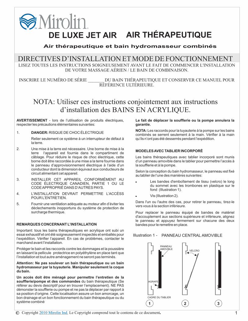
MODELESAVEC TABLIER INCORPORÉ
du bain thérapeutique (Seréférer au devis descriptif pour en trouver l’emplacement). NE PASdémonster la soufflerie ou pompe et ne pas la déplacer par rapport àsa position d’origine. Cette localisation assure un bon amorcage, unbon drainage et un bon fonctionnement du bain thérapeutique ou dusystème combiné
Les raccords pour la tuyauterie à la pompe sur les bainscombinés se serrent seulement à la main. Vérifier à la mainqu’ils n’ont pas été desserrés pendant l’expédition.
Les bains thérapeutiques avec tablier incorporé sont munisd’un panneau amovible dans le tablier pour permettre l’accès àla soufflerie et à la pompe.
Selon la conception du bain hydromasseur, le panneau est fixéau tablier de l’une des manières suivantes:
Les bandes d'emboîtement de tissu (velcro) le longdu sommet avec les trombones en plastique sur lefond (Illustration 1).
Vis (Illustration 2).
!
!
Dans l'un ou l'autre des cas, pour retirer le panneau, tirez-levers vous à la section inférieure.
Pour replacer le panneau équipé de bandes de matérield'accouplement aux sections supérieure et inférieure, alignezle panneau et appuyez fermement sur chacune des deuxbandes pour le remettre en place.
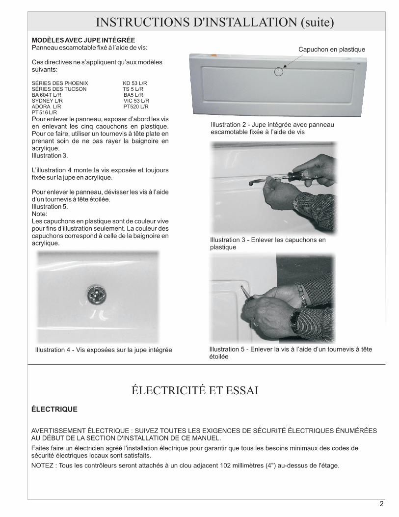
INSTRUCTIONS D'INSTALLATION (suite)MODÈLESAVEC JUPE INTÉGRÉEPanneau escamotable fixé à l’aide de vis:
Ces directives ne s’appliquent qu’aux modèlessuivants:
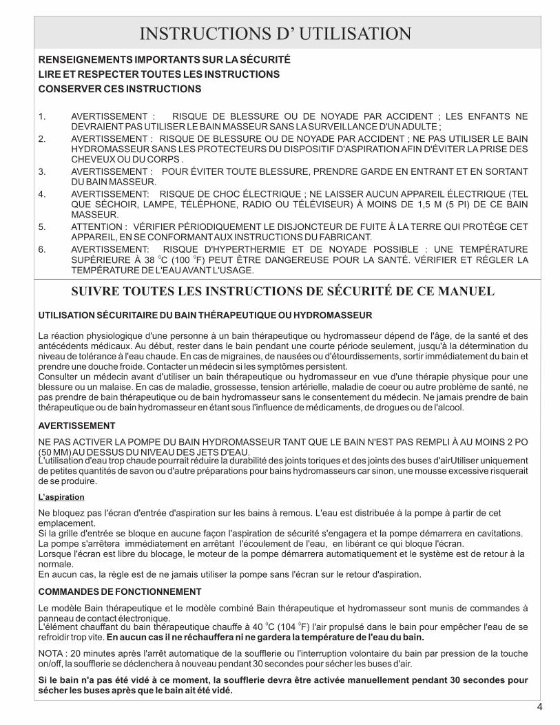
Pour enlever le panneau, exposer d’abord les visen enlevant les cinq caouchons en plastique.Pour ce faire, utiliser un tournevis à tête plate enprenant soin de ne pas rayer la baignoire enacrylique.Illustration 3.
L’illustration 4 monte la vis exposée et toujoursfixée sur la jupe en acrylique.
Pour enlever le panneau, dévisser les vis à l’aided’un tournevis à tête étoilée.Illustration 5.Note:Les capuchons en plastique sont de couleur vivepour fins d’illustration seulement. La couleur descapuchons correspond à celle de la baignoire enacrylique.
Illustration 2 - Jupe intégrée avec panneauescamotable fixée à l’aide de vis
Illustration 3 - Enlever les capuchons enplastique
Illustration 4 - Vis exposées sur la jupe intégrée Illustration 5 - Enlever la vis à l’aide d’un tournevis à têteétoilée
ÉLECTRICITÉ ET ESSAI
ÉLECTRIQUE
AVERTISSEMENT ÉLECTRIQUE : SUIVEZ TOUTES LES EXIGENCES DE SÉCURITÉ ÉLECTRIQUES ÉNUMÉRÉESAU DÉBUT DE LA SECTION D'INSTALLATION DE CE MANUEL.
Faites faire un électricien agréé l'installation électrique pour garantir que tous les besoins minimaux des codes desécurité électriques locaux sont satisfaits.
NOTEZ : Tous les contrôleurs seront attachés à un clou adjacent 102 millimètres (4") au-dessus de l'étage.
2
Capuchon en plastique
INSTRUCTIONS D’INSTALLATION (suite)
RACCORDS ÉLECTRIQUES
Massage Thérapeutique
C O M M A N D E É L E C T R O N I Q U E , M A S S A G ETHÉRAPEUTIQUE ET COMBINÉ
Le panneu de contact électronique de dont sont munis lesmodèles Massage thérapeutique et Combiné est connecté à lasoufflerie en usine. Vérifier que le connecteur est bien fixé aupanneau de contact sous la paroi.
L'installation doit se conformer aux codes locaux de sécuritéélectrique. Seules les exigences générales sont mentionnées ci-dessous. Elles ne couvrent pas toutes les situations ni tous lesdétails.
Un circuit séparé de 15 A, 115 V est requis, protégé par une priseavec disjoncteur de fuite à la terre de classe A d'une intensité de 15A.
Le câble venant du coffret de branchement devrait comporter deuxconducteurs plus une mise à la terre. Un conducteur n 14 estsuffisant pour les distances allant jusqu'à 100 pi (30 m).
Pour l'air Pour le massage aérien, la connexion électrique est uneclasse standard un GFCI - le réceptacle de NEMA.
Certains codes locaux peuvent exiger un sectionneur.Celui-ci peut être installé dans le mur ou près du moteur dans lecompartiment de service.
S'il est installé au mur, il doit se situer à au moins 1,5 m (5 pi) du bainde sorte que la personne dans le bain ne puise pas l'atteindre.
S'il est installé dans le compartiment de service, il devrait être fixésur un montant et non pas directement sous le bain.Le sectionneurpeut être un interrupteur mural normal tant que son intensiténominale est au moins aussi élevée que l'intensité de protectionindiquée ci-dessus.
o
Combinaison de baignoire à remous /massage parbulles d'air
Le souffleur de l'option de massage par bulles d'air et lapompe de la baignoire à remous exigent chacun un circuit de15 A et de 115 V, c'est-à-dire deux fils distincts du coffret debranchement avec une protection DFT de Catégorie A.
Le câble partant du coffret de branchement doit être un fil de14/2 qui est approprié pour les distances allant jusqu'à 100 pi(30 m).
Si les codes locaux exigent un interrupteur général, il doits'agir d'un interrupteur double installé dans le compartimentde service fixé sur un montant et non directement sur labaignoire.
3
N
NBV
NB
V
NBV
GFCI
GFCI
NB
V
N
VV
BB
12
RTM
on off
off
on
off
on
SOUFFLERIE Figure 6 - Les Connexions deCombinaison de Massage/Tourbillon d'air
POMPE DE LA BAIGNOIREÀ REMOUS
B1 - ALIMENTATION DE 110V1- NOIR1- BLANC (NEUTRE)1 - VERT (MISE À LA TERRE)
B2 - ALIMENTATION DE 110V1- NOIR1- BLANC (NEUTRE)1 - VERT (MISE À LA TERRE)
PANNEAU DECONTACTÉLECTRONIQUE
BOÎTE DECONTROLE(TOURBILLON)
BOÎTE DECONTROLE(JET AIR)
B1 - ALIMENTATION DE 110V1- NOIR1- BLANC (NEUTRE)1 - VERT (MISE À LA TERRE)
B2 - ALIMENTATION DE 110V1- NOIR1- BLANC (NEUTRE)1 - VERT (MISE À LA TERRE)
DU PANNEAU DEDE SERVICE 110V, 15 A
DU PANNEAU DEDE SERVICE 110V, 15 A
INSTRUCTIONS D’ UTILISATIONRENSEIGNEMENTS IMPORTANTS SUR LASÉCURITÉ
LIRE ET RESPECTER TOUTES LES INSTRUCTIONS
CONSERVER CES INSTRUCTIONS
1.
2.
3.
4.
5.
6.
SUIVRE TOUTES LES INSTRUCTIONS DE SÉCURITÉ DE CE MANUEL
AVERTISSEMENT
AVERTISSEMENT : RISQUE DE BLESSURE OU DE NOYADE PAR ACCIDENT ; LES ENFANTS NEDEVRAIENT PAS UTILISER LE BAIN MASSEUR SANS LASURVEILLANCE D'UNADULTE ;AVERTISSEMENT : RISQUE DE BLESSURE OU DE NOYADE PAR ACCIDENT ; NE PAS UTILISER LE BAINHYDROMASSEUR SANS LES PROTECTEURS DU DISPOSITIF D'ASPIRATION AFIN D'ÉVITER LA PRISE DESCHEVEUX OU DU CORPS .AVERTISSEMENT : POUR ÉVITER TOUTE BLESSURE, PRENDRE GARDE EN ENTRANT ET EN SORTANTDU BAIN MASSEUR.AVERTISSEMENT: RISQUE DE CHOC ÉLECTRIQUE ; NE LAISSER AUCUN APPAREIL ÉLECTRIQUE (TELQUE SÉCHOIR, LAMPE, TÉLÉPHONE, RADIO OU TÉLÉVISEUR) À MOINS DE 1,5 M (5 PI) DE CE BAINMASSEUR.ATTENTION : VÉRIFIER PÉRIODIQUEMENT LE DISJONCTEUR DE FUITE À LA TERRE QUI PROTÈGE CETAPPAREIL, EN SE CONFORMANTAUX INSTRUCTIONS DU FABRICANT.AVERTISSEMENT: RISQUE D'HYPERTHERMIE ET DE NOYADE POSSIBLE : UNE TEMPÉRATURESUPÉRIEURE À 38 C (100 F) PEUT ÊTRE DANGEREUSE POUR LA SANTÉ. VÉRIFIER ET RÉGLER LATEMPÉRATURE DE L'EAUAVANT L'USAGE.
La réaction physiologique d'une personne à un bain thérapeutique ou hydromasseur dépend de l'âge, de la santé et desantécédents médicaux. Au début, rester dans le bain pendant une courte période seulement, jusqu'à la détermination duniveau de tolérance à l'eau chaude. En cas de migraines, de nausées ou d'étourdissements, sortir immédiatement du bain etprendre une douche froide. Contacter un médecin si les symptômes persistent.Consulter un médecin avant d'utiliser un bain thérapeutique ou hydromasseur en vue d'une thérapie physique pour uneblessure ou un malaise. En cas de maladie, grossesse, tension artérielle, maladie de coeur ou autre problème de santé, nepas prendre de bain thérapeutique ou de bain hydromasseur sans le consentement du médecin. Ne jamais prendre de bainthérapeutique ou de bain hydromasseur en étant sous l'influence de médicaments, de drogues ou de l'alcool.
NE PAS ACTIVER LA POMPE DU BAIN HYDROMASSEUR TANT QUE LE BAIN N'EST PAS REMPLI À AU MOINS 2 PO(50 MM)AU DESSUS DU NIVEAU DES JETS D'EAU.L'utilisation d'eau trop chaude pourrait réduire la durabilité des joints toriques et des joints des buses d'airUtiliser uniquementde petites quantités de savon ou d'autre préparations pour bains hydromasseurs car sinon, une mousse excessive risqueraitde se produire.
Le modèle Bain thérapeutique et le modèle combiné Bain thérapeutique et hydromasseur sont munis de commandes àpanneau de contact électronique.L'élément chauffant du bain thérapeutique chauffe à 40 C (104 F) l'air propulsé dans le bain pour empêcher l'eau de serefroidir trop vite.
NOTA : 20 minutes après l'arrêt automatique de la soufflerie ou l'interruption volontaire du bain par pression de la toucheon/off, la soufflerie se déclenchera à nouveau pendant 30 secondes pour sécher les buses d'air.
0 0
0 0
UTILISATION SÉCURITAIRE DU BAIN THÉRAPEUTIQUE OU HYDROMASSEUR
COMMANDES DE FONCTIONNEMENT
En aucun cas il ne réchauffera ni ne gardera la température de l'eau du bain.
Si le bain n'a pas été vidé à ce moment, la soufflerie devra être activée manuellement pendant 30 secondes poursécher les buses après que le bain ait été vidé.
L’aspiration
Ne bloquez pas l'écran d'entrée d'aspiration sur les bains à remous. L'eau est distribuée à la pompe à partir de cetemplacement.Si la grille d'entrée se bloque en aucune façon l'aspiration de sécurité s'engagera et la pompe démarrera en cavitations.La pompe s'arrêtera immédiatement en arrêtant l'écoulement de l'eau, en libérant ce qui bloque l'écran.Lorsque l'écran est libre du blocage, le moteur de la pompe démarrera automatiquement et le système est de retour à lanormale.En aucun cas, la règle est de ne jamais utiliser la pompe sans l'écran sur le retour d'aspiration.
4
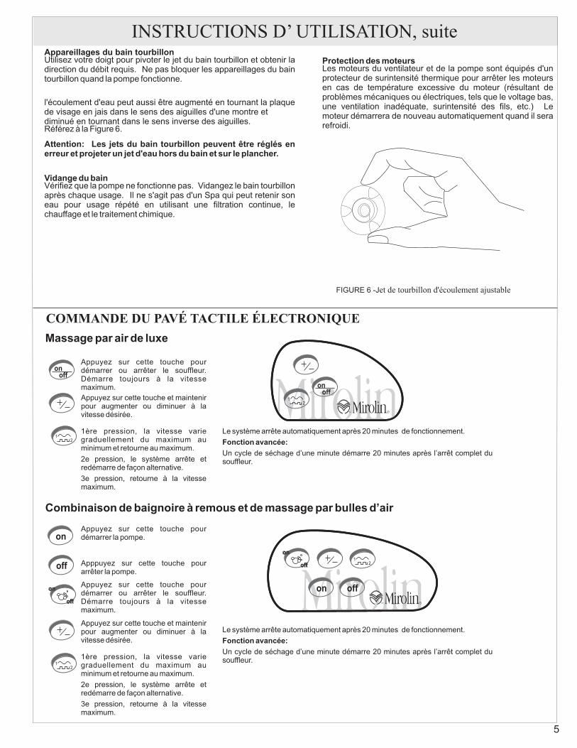
Appareillages du bain tourbillon
Attention: Les jets du bain tourbillon peuvent être réglés enerreur et projeter un jet d'eau hors du bain et sur le plancher.
Vidange du bain
Protection des moteursUtilisez votre doigt pour pivoter le jet du bain tourbillon et obtenir ladirection du débit requis. Ne pas bloquer les appareillages du baintourbillon quand la pompe fonctionne.
Référez à la Figure 6.
Vérifiez que la pompe ne fonctionne pas. Vidangez le bain tourbillonaprès chaque usage. Il ne s'agit pas d'un Spa qui peut retenir soneau pour usage répété en utilisant une filtration continue, lechauffage et le traitement chimique.
Les moteurs du ventilateur et de la pompe sont équipés d'unprotecteur de surintensité thermique pour arrêter les moteursen cas de température excessive du moteur (résultant deproblèmes mécaniques ou électriques, tels que le voltage bas,une ventilation inadéquate, surintensité des fils, etc.) Lemoteur démarrera de nouveau automatiquement quand il serarefroidi.
l'écoulement d'eau peut aussi être augmenté en tournant la plaquede visage en jais dans le sens des aiguilles d'une montre etdiminué en tournant dans le sens inverse des aiguilles.
INSTRUCTIONS D’ UTILISATION, suite
COMMANDE DU PAVÉ TACTILE ÉLECTRONIQUE
5
Massage par air de luxe
12
RTM
onoff
12
RTM
on off
off
on
off
on
12
onoff
Appuyez sur cette touche pourdémarrer ou arrêter le souffleur.Démarre toujours à la vitessemaximum.Appuyez sur cette touche et maintenirpour augmenter ou diminuer à lavitesse désirée.
1ère pression, la vitesse variegraduellement du maximum auminimum et retourne au maximum.
2e pression, le système arrête etredémarre de façon alternative.
3e pression, retourne à la vitessemaximum.
Le système arrête automatiquement après 20 minutes de fonctionnement.
Un cycle de séchage d’une minute démarre 20 minutes après l’arrêt complet dusouffleur.
Fonction avancée:
Combinaison de baignoire à remous et de massage par bulles d’air
12
Apppuyez sur cette touche pourarrêter la pompe.
off
on
off
on
on
off
Appuyez sur cette touche pourdémarrer la pompe.
Appuyez sur cette touche pourdémarrer ou arrêter le souffleur.Démarre toujours à la vitessemaximum.
Appuyez sur cette touche et maintenirpour augmenter ou diminuer à lavitesse désirée.
1ère pression, la vitesse variegraduellement du maximum auminimum et retourne au maximum.
2e pression, le système arrête etredémarre de façon alternative.
3e pression, retourne à la vitessemaximum.
Le système arrête automatiquement après 20 minutes de fonctionnement.
Un cycle de séchage d’une minute démarre 20 minutes après l’arrêt complet dusouffleur.
Fonction avancée:
FIGURE 6 -Jet de tourbillon d'écoulement ajustable
INSTRUCTIONS IMPORTANTES POURL'ÉLECTRICITÉ
AVERTISSEMENT - Pour l'utilisation des produits électriques, desprécautions de base devraient toujours être observées, incluant cequi suit :
DANGER: RISQUE DE CHOC ÉLECTRIQUE.
AVERTISSEMENT
"
"
"
"
Branchez seulement sur un circuit protégé par uninterrupteur de mise à terre du circuit (GFCI).
Utilisez uniquement que des conducteurs en cuivre.
La mise à terre est requise. Assurez-vous que le chauffe-bain et la pompe sont mis à terre adéquatement et que lapompe est MÉTALLISÉE tel que requis.
Le chauffe-bain doit être installé par un électricien qualifiéselon les normes du Code National de l'Électricité et selontous les standards locaux.
Avant d'utiliser la pompe et/ou le chauffe-bain, vérifiez le«GFCI» en appuyant sur le bouton d'essai (TEST). La pompeet le chauffe-bain ne devraient pas fonctionner. Pour activerde nouveau, appuyez sur le bouton de réactivation (RESET).Si le GFCI ne fonctionne pas comme décrit ci-dessus, lecourant de mise à terre est présent. NE PAS opérer la pompeet/ou le chauffe-bain avant d'avoir remédier à la situation.
INSTRUCTIONS D’ UTILISATION, suite
CHAUFFE-BAIN EN LIGNE(Options)
INTRODUCTION
Votre chauffe-bain tourbillon AquaHest utilise une«technologie intelligente», pour vous offrir de nombreusesannées de satisfaction. Sa conception électronique de hautetechnologie offre une utilisation sûre et sans problème avec uncontrôle précis de la température de l'eau.
Aucun réglage n'est requis, quand le bain tourbillon estrempli à l'eau chaude, alors que le dispositif de chauffe- baintourbillon AquaHeat de haute technologie conservera latempérature de l'eau à 104°F. Pour refroidir l'eau, ajoutezsimplement de l'eau froide au besoin.
Dans l'éventualité où la température excéderait 104°F, lechauffe-bain s'éteindra automatiquement. Pour le régler denouveau, attendez jusqu'au moment où la températuredescend sous 104 °F et interrompez le courant au chauffe-bain en réglant de nouveau l'interrupteur du circuit sur lepanneau électrique principal. S'il y a interruption fréquentede limite haute, consultez un électricien qualifié.
Dans l'éventualité ou la pompe ne fonctionne pas ou nefournit pas le débit suffisant, le chauffe-bain ne sera pasactivé. Pour y remédier, consultez un électricien qualifié.
Protection de limite de température
Interrupteur à vide
Spécifications:
1.5 kW"
"
115 volts, 20 amp« »En ligne
Interrupteur à vide
B - NOIRG - VERTW - BLANC
B
WG
CONNEXION ÉLECTRIQUE
BranchementCircuit20A/115V
TESTGFCI
DE LASUCCION
INSTALLATION: VERSION IN LIGNE DE LA SUCCIONNLINE FROM SUCTION VERSION
COURANT - NOIRMASSE - VERTCOMB. - BLANC
POMPE
B
WG
B
WG
VERS LES JETS
6
INSTRUCTIONS D’UTILISATION, suiteIMPORTANTES INSTRUCTIONS DE SÉCURITÉ
AVERTISSEMENT
LISEZ ATTENTIVEMENT ET OBSERVEZ TOUTES LESINSTRUCTIONS.
DANGER
AVERTISSEMENT
Pour l'utilisation de cette unité, desprécautions de base devraient toujours être observées,incluant ce qui suit :
Pour réduire le risque de noyade, ne permettezpas aux enfants d'utiliser le bain tourbillon sans la supervisionpar un adulte en tout temps.
Utilisez ce chauffe-bain pour son usage exclusifseulement, tel que décrit dans ce manuel. Ne pas modifier lechauffe-bain. Des chocs électriques pourraient se produire.
Ne pas utiliser le bain tourbillon ou le chauffe-bain avec lescouvercles de succion enlevés ; Assurez-vous que lescouvercles de succion sont installés de manière adéquateavant l'usage.
Le chauffe-bain doit être branché sur un circuit électriquequi est protégé par un interrupteur de mise à terre du circuit(GFCI). Le «GFCI» devrait être fourni par l'installateur etdevrait être vérifié sur une base routinière.Pour vérifier le «GFCI», appuyez sur le bouton «TEST», lapompe et le chauffe-bain ne devraient pas fonctionner.Appuyez sur le bouton «RESET» et la pompe et le chauffe-bain devraient fonctionner de nouveau. Si le «GFCI» nefonctionne pas de cette façon, il existe un débit de courant demise à terre, indiquant la possibilité d'un choc électrique. NEPAS utiliser la pompe et le chauffe-bain sous ces conditions.
Obtenez les services d'un électricien qualifié pourremédier au problème avant l'usage.
L'immersion prolongée dans l'eau chaude pourraitcauser l'hypothermie. Les causes, les symptômes et leseffets de l'hypothermie seraient décrites comme suit :L'hypothermie se produit quand la température internedu corps atteint un niveau de plusieurs degrés au-dessus de la température normale du corps de 98.6°F.Les symptômes de l'hypothermie incluent :
Une augmentation de la température interne du corps.ÉtourdissementÉvanouissement
Les effets de l'hypothermie incluent :L'insensibilité à la chaleurLe manque de reconnaître la nécessité de sortir du
bainL'inconscience d'un risque en coursDommage au fœtus chez les femmes enceintesL'impossibilité physique de sortir du bainL'évanouissement qui résulterait en un danger de
noyade
L'usage de l'alcool, de la drogue oudes médicaments peut augmenter de manièresignificative le risque de l'hypothermie fatale.
1.
2.
3.
4.
5 .
6.
a)b)c)
a)b)
c)d)e)f)
Bain thérapeutique
Accessoiries d’aspiration pour l’hydromassage
Le cycle de séchage de 30 secondes après que le bain ait été vidé est important et se déclenchera automatiquement après le bainthérapeutique.
Si le bain a été utilisé simplement comme baignoire ordinaire ou que le modèle combiné a été utilisé uniquement comme hydromasseur, lebain thérapeutique doit être mis en marche manuellement pendant 30 secondes après qu'on ait vidé le bain.
Dans le système d'hydromassage du modèle combiné, la grille d'aspiration est celle illustrée à la illustration 8. Si l'installation nécessite lenettoyage, déviser les vis de l'écran de la couverture d 'aspiration. Retirer le couvercle et enlevez toute accumulation de charpie ou d'autresmatières. Pour remettre le couvercle, assurez-vous que les vis sont a la bonne place . Mettre les vis en place et bien serrées pour s'assurerqu'il n'y a pas d'écart entre les parois de la cuve et le couvercle d'aspiration.
DIRECTIVES D’ENTRETIEN
7
Essayage de succion mural
Écran de couverture de succion
Illustration 8 -APPAREILLAGE DE RETOUR DE SUCCION
Nettoyer et purger
Mise en garde!
Surface acrylique
Restauration du lustre de la surface
Réparations mineures de la surface
Finis spéciaux des accessoires
Les tuyaux internes de votre baignoire à remousdoivent être nettoyés régulièrement pour réduire l'accumulation desaleté, d'écume ou toute autre accumulation. Ce nettoyage doitêtre effectué même si vous utilisez la baignoire sans les jets.Utilisez la procédure suivante pour nettoyer et purger la baignoireau moins une fois par semaine si la baignoire est utilisée chaquejour ou pour la nettoyer tous les trois jours si vous ne l'utilisezqu'occasionnellement.
Remplissez la baignoire d'eau tiède jusqu'au dessus desjets et ajoutez une tasse de détergent de lave-vaisselleElectrasol Citron Gel Super Nettoyant en Profondeur. Pouréconomiser l'eau, vous pouvez ajouter le détergent à l'eaude la baignoire après l'avoir utilisée et avant de la vider.Faites fonctionner la pompe et les jets pendant 10 minutes.Remplissez de nouveau la baignoire d'eau tiède fraîchejusqu'au-dessus des jetsFaites fonctionner la pompe et les jets pendant 5 minutes.Videz la baignoire.
La feuille d'acrylique qui constitue la surface du bain fournit l'une dessurfaces les plus durables que l'on puisse trouver dans les salles debain modernes. L'utilisation d'un détersif liquide doux, de savon etd'eau ou de nettoyant moussant permet de la garder brillante et bienlisse. NE JAMAIS UTILISER de solvants aromatiques, de
nettoyants abrasifs, de produits ou tampons à récurer, d'agentsde nettoyage liquides très forts ou un produit qui risqueraitd'endommager ou de ternir la surface du bain.Nousrecommandons l'utilisation périodique du poli pur acrylique etfibre de verre Mirogloss pour conserver l'apparence du bain.Ce produit est en vente dans le commerce.
Pour redonner du lustre à la surface, appliquer un composé defrottage très fin et polir la surface à la main ou à l'aide d'unpolisseur électrique. Finir en appliquant Mirogloss ou une cirepour automobile de bonne qualité.
Enlever les rayures et les traces de frottement mineurescomme suit. Frotter d'abord la surface humide avec du papierde verre à 600 grains jusqu'à ce que la surface soit lisse. Puisrestaurer le lustre comme décrit dans RESTAURATION DULUSTRE DE LASURFACE.
NE PAS UTILISER de poudres, de tampons ni de liquides quicontiennent des agents abrasifs. De nombreux nettoyantsménagers y compris les détersifs pour les lave-vaissellesautomatiques sont abrasifs et endommageraient les surfacesplaquées ou colorées ainsi que le fini du bain en acrylique.
•
•
•
•
•
MD
MD
DIRECTIVES ENTRETIEN, suite
La soufflerie ne fonctionne pas :
Vérifier que la touche de commande électronique estcorrectement reliée.Vérifier l'alimentation électrique. Réenclencher ledisjoncteur ou remplacer le fusible au besoin.Vérifier le disjoncteur de fuite à la terre. Réenclenchersi déclenché.Si le système a fonctionné pendant un certain temps, laprotection thermique a pu arrêter le moteur. Éteindre lesystème et attendre au moins 30 minutes avant de leréutiliser.
Le moteur fonctionne mais aucun air ne vient par les buses :
Vérifier que le tube flexible principal reliant le collecteurà la soufflerie est connecté correctement. Au besoin,raccorder et serrer les collets.
Les sorties d'air sont obstruées :
Si les sorties d'air des buses sont bloquées par dusavon ou d'autres résidus, remplir le bain d'eau tiède,frotter les buses doucement avec une vielle brosse àdents, puis ACTIVER le système et le DÉSACTIVERplusieurs fois.
L'air propulsé semble froid :
Si le bain est posé contre deux murs extérieurs, il estrecommandé de fournir une isolation adéquate pources murs extérieurs afin de réduire la perte de chaleur.
2. Sur l'utilisation initiale quand l'eau de bain est trèschaude l'éclatement initial d'air par les lignes se sentira
frais parce que l'air est à la température plus basse quel'eau de bain. Le téléphone prend 5 minutes pouratteindre la température opérante optimale.
3. Les gens sensibles de peau pourraient connaître le soi-disant "effet aérien froid" qui est provoqué par lasensation de bulles d'air courant le long de la peaumouillée et fournissant au baigneur avec une sensationfrissonnant. Déplacez juste votre corps légèrement loindu jet le plus proche à
L'élément chauffant n'est pas conçu pour chauffer l'eaudu bain, mais pour préchauffer l'air propulsé à latempérature du corps 36 à 37 C (97 à 98 F).Après 5 minute. Du temps dirigé l'air laisse le réservoir detéléphone à 40°C (104°F) et alors qu'il atteint l'orifice enjais il est à 36-37°C (97-98°F).
La commande électronique de votre système estprogrammée pour que 20 minutes après l'arrêt dusystème, un cycle de séchage se déclencheautomatiquement. Ce cycle souffle de l'air chaud dans latuyauterie pendant 30 secondes afin de sécher les têtesde buse. Ne pas interrompre le cycle de séchage. Si lecycle démarre et est stoppé, le programmerecommencera du début et un nouveau cycle de séchagedébutera 20 minutes plus tard.
0 0
1.
2.
3.
4.
1.
1.
1.
NOTA:
Le cycle de séchage:
1.
GUIDE DE DÉPANNAGE
8
9
A
B
C
5. Jet Body
9
1
4
2
3
7
6
8
9
10
SYSTÈME DU BAINTHÉRAPEUTIQUE1. Soufflerie2. Tube à air flexible principal et collets3. Ensemble du clapet de retenue et du collecteur4. Tubes des buses à air5. Corps de buse
A. Air de buseB. Rondelle en néoprèneC. Code en «L»
6. Panneau de contact électronique7. Câble du planneau de contact8. Boîte de controle9. Le câble de boîte de contrôle connecte avec la soufflerie10.
*Pour des pièces hydromasseur, de demanderle manuel d’ installation de l’hydromasseuren acrylique Mirolin.
Alimentation électrique avec la prise de courant de NEMA.
A
B
C
5. Corps de buse
4
2
3
AIR THÉRAPEUTIQUE ET BAINHYDROMASSEUR COMBINÉS
8. la boîte de contrôle (le massage d'air)9. le câble de boîte de contrôle (connecte avec la soufflerie)10. l'alimentation (les données)11. le câble de coussin de touche (le Système de Tourbillon)12. la boîte de contrôle (le Système de Tourbillon)13. Le câble de boîte de contrôle connecte avec le pompe/moteur detourbillon14. l'alimentation (les données) le câble de15. connecte la boîte de contrôle avec le pompe/moteur de tourbillon
1. Soufflerie2. Tube à air flexible principal et collets3. Ensemble du clapet de retenue et du collecteur4. Tubes des buses à air5. Corps de buse
A. Air de buseB. Rondelle en néoprèneC. Code en «L»
6. Panneau de contact électronique7. Câble du planneau de contact
*Pour des pièces hydromasseur, de demanderle manuel d’ installation de l’hydromasseuren acrylique Mirolin.
13
9 87
10
IDENTIFICATION DES PIÈCESRÉFÉRENCE DU DESSIN DU SYSTÈME DE BAIN TOURBILLON
NOTE : POUR COMMANDER :** Précisez la couleur ou le fini
**
NO DESCRIPTION
8.0 Raccord-union de rupture 1-1/2 po, 38mm9.1 L'air allume / de la pompe9.2 Joint de changement aérien9.3 Changement aérien noix de PVC10.0 L’air alve10.0 Une pince12.0
entrée contrôle v
Collecteur d'air13.0 T - Connecteur14.0 Pipe à eau en ligne flex 1po, 25mm15.0 Pipe d'aspiration flexible - 3/8 po,10mm16.0 V - Montage17.0 Assemblage du jet dorsal
NO DESCRIPTION
1.0 Moteur électrique et pompe1.1 Raccord de pompe2.0 1-1/2 po, 38mm3.0 Raccord de pression 1-1/2 po, 38mm4.1 Coude d'aspiration de 90º - 1 ½ po, 38mm4.2 Corps du drain d'aspiration (bride d'aspiration)4.3 Plaque de recouvrement du drain d'aspiration4.4 Vis5.06.1 Corps du jet6.2 F6.3 **7.1 Corps du jet pour pieds7.2 Gasket7.3 F7.4 du jet pour pieds
Tuyau d'aspiration
Air pipe chaîne de montage flexible -3/8 po,10mm
ixation au murTêtière
ixation au murTêtière
11
12
5
7.1
7.2
7.3
7.4
9.1
9.2
9.3
4.1
4.2
4.3
4.4
1
2
36.1
6.2
6.3
11
10
12
13
814
15
1.1
17
17.3
17.2
17.1
V - Montage
SYSTÈME DE D’HYDROMASSAGE TYPIQUE SANS JETS DORSAUX
SYSTÈME D’HYDROMASSAGE AVEC JETS DORSAUX A PLUS DE ASSEMBLAGE DU JET DORSAL,COLLECTEUR D’AIR DE 4 PORTS ET V-MONTAGE
Collecteur d'airde 4 ports
Corps du jetdorsal
Gasket
Têtière**
Assemblagedu jet dorsal
Nous tenons à ce que vous soyez entièrement satisfait de nos produits et services. Si vous avez dez commentaires ou dessuggestions, veuillez composer sans frais le 1-800-MIROLIN.