DEMETER observations of ELF waves injected with the HAARP HF transmitter M. Platino, 1 U. S. Inan, 1 T. F. Bell, 1 M. Parrot, 2 and E. J. Kennedy 3 Received 30 March 2006; revised 12 June 2006; accepted 27 June 2006; published 17 August 2006. [1] Modulated HF heating of the auroral electrojet is used to inject ELF signals into the magnetosphere that are observed on the low altitude DEMETER spacecraft. The HF heater is a component of the High-Frequency Active Auroral Research Program (HAARP) facility in Gakona, Alaska, (located at L 4.9). Simultaneous observations of all six components of the ELF electromagnetic fields on the DEMETER spacecraft are used to estimate the total ELF power radiated downward into the Earth-ionosphere waveguide. ELF signals generated by the HAARP heater are also simultaneously observed at a nearby ground-based site, allowing a comparison of the ELF power in the Earth- ionosphere waveguide versus that detected on DEMETER. The estimated values of power onboard DEMETER at different frequencies range from 0.32W to 4W, while the values of power estimated from a ground receiver at a distance of 36 km from HAARP range from 2.71W to 4.22W. Citation: Platino, M., U. S. Inan, T. F. Bell, M. Parrot, and E. J. Kennedy (2006), DEMETER observations of ELF waves injected with the HAARP HF transmitter, Geophys. Res. Lett., 33, L16101, doi:10.1029/2006GL026462. 1. Introduction [2] Generation of ELF/VLF waves by modulating the D region conductivity in the vicinity of the auroral electrojet using a powerful High Frequency (HF) heater is by a now well established technique [Stubbe and Kopka, 1977; Rietveld et al., 1989; Inan et al., 2004, and references therein]. The mechanism involves the periodic modification of the electron temperature in the D and lower E regions of the ionosphere, which leads to periodic changes in the Pedersen and Hall conductivities, resulting in periodically changing electric current density in the electrojet and thus radiation. Under such circumstances, the heated ionospheric area with its immediate surroundings acts as a huge ‘polar-electrojet’ antenna, radiating primarily at a frequency corresponding to the modulation frequency of the HF carrier. [3] Spacecraft observations of ELF/VLF waves generated by different HF heating facilities have been carried out on both low [Lefeuvre et al., 1985; James et al., 1984; Inan and Helliwell, 1985], and high-altitude spacecraft [James et al., 1990; Bell et al., 2004; Platino et al., 2004]. Nevertheless, the degree to which modulated HF heating can be consis- tently used to inject ELF/VLF waves upward into the overlying magnetosphere, and the total ELF power radiated by such a source is not understood at a quantitative level. [4] In this paper, we present recent observations on the DEMETER spacecraft of electromagnetic ELF waves pro- duced through modulation of auroral electrojet currents, and use the simultaneously observed multiple field components to estimate the total ELF power radiated into the Earth- ionosphere waveguide by the electrojet current modified by the HAARP HF heater. The observations reported herein were carried out over the ELF frequency range of 118 Hz to 1197 Hz on the 3-axis stabilized DEMETER satellite, at an altitude of 730 km in an orbit of 98.3° of inclination. Ground observations of the HAARP ELF transmitted sig- nals are also provided and compared to the DEMETER observations. A numerical raytracing model was used to simulate the propagation of ELF whistler mode waves from the ionospheric generation regions up to the spacecraft and to estimate the spatial extent of the region in the ionosphere illuminated by ELF waves. 2. HAARP-DEMETER Campaign [5] The DEMETER spacecraft is a low altitude satellite, with two sets of antennas, one set to measure the three components of the plasma wave electric field using the electric sensors of the Electric Field Instrument (ICE) and one set to measure the three components of the plasma wave magnetic field using the magnetic sensors of the Instrument Magnetometer Search-Coil (IMSC), operating over a fre- quency range of 10 Hz to 1.25 kHz in the burst mode [Parrot, 2002]. Attempts to observe the HAARP ELF signals on DEMETER were carried out during passes close to the HAARP facility, on spacecraft trajectories whose subsatellite points on the ground were at a distance no larger than 200 km from HAARP at the closest point. The HAARP HF heater is located near Gakona, Alaska, at a site with geographic coordinates of 62.4° (North) latitude, 145.2° (West) longitude and geomagnetic coordinates of 63.1° (North) latitude and 92.4° (West) longitude. At HAARP, an HF phased – array transmitter is used to heat small, well-defined volumes of the ionosphere with high power radio signals in the 2.8 to 10 MHz frequency range. At the time these experiments were performed, the HAARP HF transmitter had a total maximum radiated power capability of 960 kW. The ELF/VLF signal format shown in Figure 1 was impressed upon a 3.3 MHz carrier through sinusoidal amplitude modulation, with a modula- tion index of 0.95. The HF carrier frequency was chosen to provide maximum heating in the D region of the ionosphere [James et al., 1984], taking into account the allocated frequencies at which HAARP can transmit at its highest GEOPHYSICAL RESEARCH LETTERS, VOL. 33, L16101, doi:10.1029/2006GL026462, 2006 Click Here for Full Articl e 1 Space, Telecommunications and Radioscience (STAR) Laboratory, Stanford University, Stanford, California, USA. 2 Laboratoire de Physique et Chimie de l’Environnement, Centre National de la Recherche Scientifique, Orle ´ans, France. 3 Naval Research Laboratory, Washington, D. C., USA. Copyright 2006 by the American Geophysical Union. 0094-8276/06/2006GL026462$05.00 L16101 1 of 6
Transcript
DEMETER observations of ELF waves injected with the HAARP HF
transmitter
M. Platino,1 U. S. Inan,1 T. F. Bell,1 M. Parrot,2 and E. J. Kennedy3
Received 30 March 2006; revised 12 June 2006; accepted 27 June 2006; published 17 August 2006.
[1] Modulated HF heating of the auroral electrojet is usedto inject ELF signals into the magnetosphere that areobserved on the low altitude DEMETER spacecraft. TheHF heater is a component of the High-Frequency ActiveAuroral Research Program (HAARP) facility in Gakona,Alaska, (located at L � 4.9). Simultaneous observations ofall six components of the ELF electromagnetic fields on theDEMETER spacecraft are used to estimate the total ELFpower radiated downward into the Earth-ionospherewaveguide. ELF signals generated by the HAARP heaterare also simultaneously observed at a nearby ground-basedsite, allowing a comparison of the ELF power in the Earth-ionosphere waveguide versus that detected on DEMETER.The estimated values of power onboard DEMETER atdifferent frequencies range from 0.32W to 4W, while thevalues of power estimated from a ground receiver at adistance of 36 km from HAARP range from 2.71W to4.22W. Citation: Platino, M., U. S. Inan, T. F. Bell, M. Parrot,
and E. J. Kennedy (2006), DEMETER observations of ELF waves
injected with the HAARP HF transmitter, Geophys. Res. Lett., 33,
L16101, doi:10.1029/2006GL026462.
1. Introduction
[2] Generation of ELF/VLF waves by modulating theD region conductivity in the vicinity of the auroral electrojetusing a powerfulHigh Frequency (HF) heater is by a nowwellestablished technique [Stubbe and Kopka, 1977; Rietveld etal., 1989; Inan et al., 2004, and references therein]. Themechanism involves the periodic modification of the electrontemperature in the D and lower E regions of the ionosphere,which leads to periodic changes in the Pedersen and Hallconductivities, resulting in periodically changing electriccurrent density in the electrojet and thus radiation. Undersuch circumstances, the heated ionospheric area with itsimmediate surroundings acts as a huge ‘polar-electrojet’antenna, radiating primarily at a frequency corresponding tothe modulation frequency of the HF carrier.[3] Spacecraft observations of ELF/VLF waves generated
by different HF heating facilities have been carried out onboth low [Lefeuvre et al., 1985; James et al., 1984; Inan andHelliwell, 1985], and high-altitude spacecraft [James et al.,1990; Bell et al., 2004; Platino et al., 2004]. Nevertheless,the degree to which modulated HF heating can be consis-
tently used to inject ELF/VLF waves upward into theoverlying magnetosphere, and the total ELF power radiatedby such a source is not understood at a quantitative level.[4] In this paper, we present recent observations on the
DEMETER spacecraft of electromagnetic ELF waves pro-duced through modulation of auroral electrojet currents, anduse the simultaneously observed multiple field componentsto estimate the total ELF power radiated into the Earth-ionosphere waveguide by the electrojet current modified bythe HAARP HF heater. The observations reported hereinwere carried out over the ELF frequency range of 118 Hz to1197 Hz on the 3-axis stabilized DEMETER satellite, at analtitude of �730 km in an orbit of 98.3� of inclination.Ground observations of the HAARP ELF transmitted sig-nals are also provided and compared to the DEMETERobservations. A numerical raytracing model was used tosimulate the propagation of ELF whistler mode waves fromthe ionospheric generation regions up to the spacecraft andto estimate the spatial extent of the region in the ionosphereilluminated by ELF waves.
2. HAARP-DEMETER Campaign
[5] The DEMETER spacecraft is a low altitude satellite,with two sets of antennas, one set to measure the threecomponents of the plasma wave electric field using theelectric sensors of the Electric Field Instrument (ICE) andone set to measure the three components of the plasma wavemagnetic field using the magnetic sensors of the InstrumentMagnetometer Search-Coil (IMSC), operating over a fre-quency range of 10 Hz to 1.25 kHz in the burst mode[Parrot, 2002]. Attempts to observe the HAARP ELFsignals on DEMETER were carried out during passes closeto the HAARP facility, on spacecraft trajectories whosesubsatellite points on the ground were at a distance no largerthan 200 km from HAARP at the closest point. TheHAARP HF heater is located near Gakona, Alaska, at asite with geographic coordinates of 62.4� (North) latitude,145.2� (West) longitude and geomagnetic coordinates of63.1� (North) latitude and 92.4� (West) longitude. AtHAARP, an HF phased – array transmitter is used to heatsmall, well-defined volumes of the ionosphere with highpower radio signals in the 2.8 to 10 MHz frequencyrange. At the time these experiments were performed, theHAARP HF transmitter had a total maximum radiatedpower capability of 960 kW. The ELF/VLF signal formatshown in Figure 1 was impressed upon a 3.3 MHz carrierthrough sinusoidal amplitude modulation, with a modula-tion index of 0.95. The HF carrier frequency was chosen toprovide maximum heating in the D region of the ionosphere[James et al., 1984], taking into account the allocatedfrequencies at which HAARP can transmit at its highest
GEOPHYSICAL RESEARCH LETTERS, VOL. 33, L16101, doi:10.1029/2006GL026462, 2006ClickHere
for
FullArticle
1Space, Telecommunications and Radioscience (STAR) Laboratory,Stanford University, Stanford, California, USA.
2Laboratoire de Physique et Chimie de l’Environnement, CentreNational de la Recherche Scientifique, Orleans, France.
3Naval Research Laboratory, Washington, D. C., USA.
Copyright 2006 by the American Geophysical Union.0094-8276/06/2006GL026462$05.00
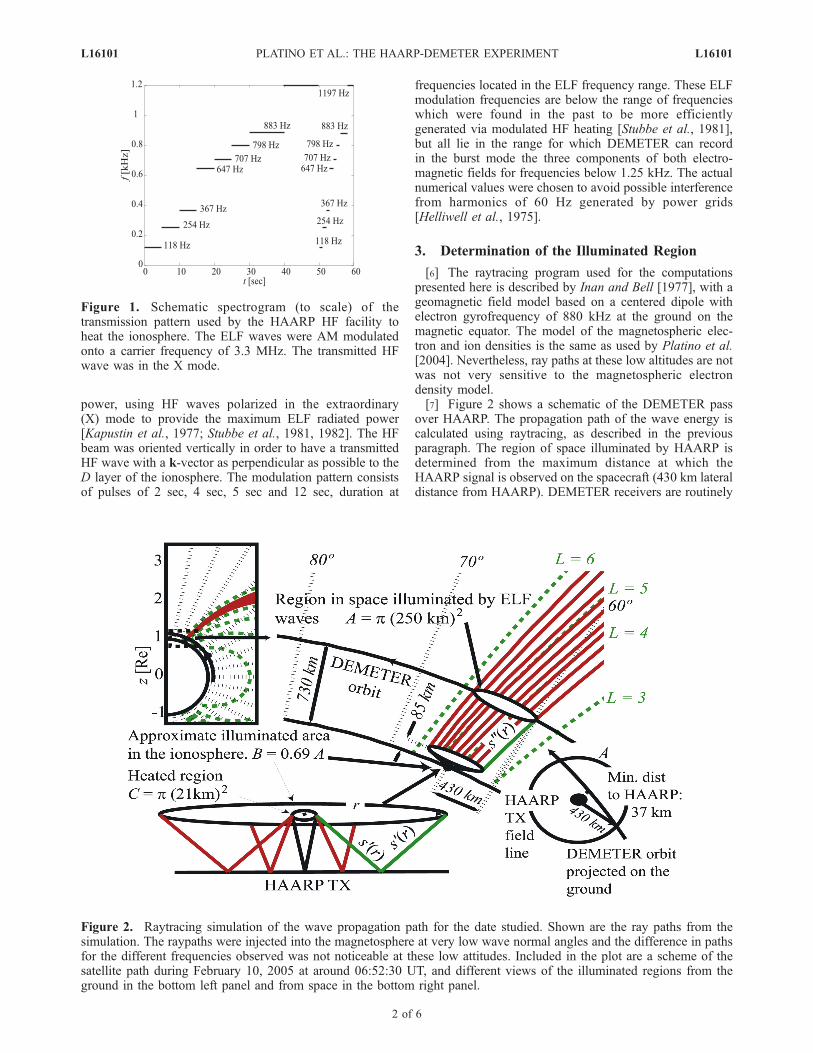
power, using HF waves polarized in the extraordinary(X) mode to provide the maximum ELF radiated power[Kapustin et al., 1977; Stubbe et al., 1981, 1982]. The HFbeam was oriented vertically in order to have a transmittedHF wave with a k-vector as perpendicular as possible to theD layer of the ionosphere. The modulation pattern consistsof pulses of 2 sec, 4 sec, 5 sec and 12 sec, duration at
frequencies located in the ELF frequency range. These ELFmodulation frequencies are below the range of frequencieswhich were found in the past to be more efficientlygenerated via modulated HF heating [Stubbe et al., 1981],but all lie in the range for which DEMETER can recordin the burst mode the three components of both electro-magnetic fields for frequencies below 1.25 kHz. The actualnumerical values were chosen to avoid possible interferencefrom harmonics of 60 Hz generated by power grids[Helliwell et al., 1975].
3. Determination of the Illuminated Region
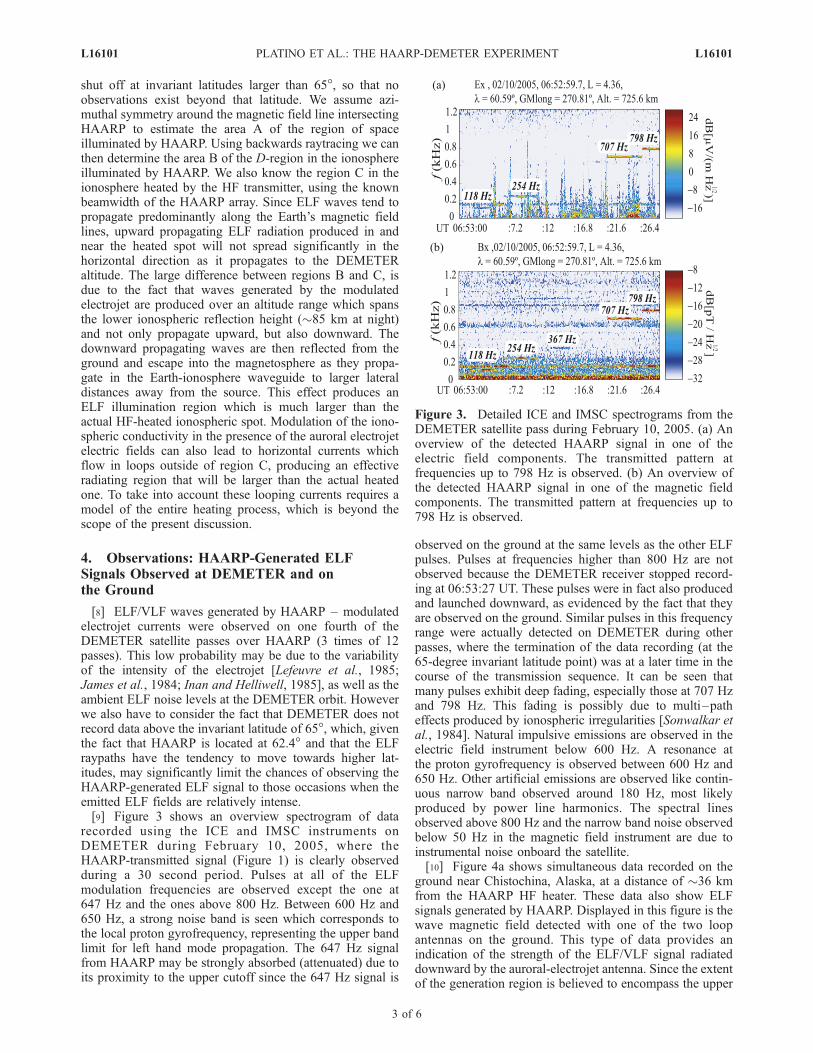
[6] The raytracing program used for the computationspresented here is described by Inan and Bell [1977], with ageomagnetic field model based on a centered dipole withelectron gyrofrequency of 880 kHz at the ground on themagnetic equator. The model of the magnetospheric elec-tron and ion densities is the same as used by Platino et al.[2004]. Nevertheless, ray paths at these low altitudes are notwas not very sensitive to the magnetospheric electrondensity model.[7] Figure 2 shows a schematic of the DEMETER pass
over HAARP. The propagation path of the wave energy iscalculated using raytracing, as described in the previousparagraph. The region of space illuminated by HAARP isdetermined from the maximum distance at which theHAARP signal is observed on the spacecraft (430 km lateraldistance from HAARP). DEMETER receivers are routinely
Figure 1. Schematic spectrogram (to scale) of thetransmission pattern used by the HAARP HF facility toheat the ionosphere. The ELF waves were AM modulatedonto a carrier frequency of 3.3 MHz. The transmitted HFwave was in the X mode.
Figure 2. Raytracing simulation of the wave propagation path for the date studied. Shown are the ray paths from thesimulation. The raypaths were injected into the magnetosphere at very low wave normal angles and the difference in pathsfor the different frequencies observed was not noticeable at these low attitudes. Included in the plot are a scheme of thesatellite path during February 10, 2005 at around 06:52:30 UT, and different views of the illuminated regions from theground in the bottom left panel and from space in the bottom right panel.
L16101 PLATINO ET AL.: THE HAARP-DEMETER EXPERIMENT L16101
2 of 6
shut off at invariant latitudes larger than 65�, so that noobservations exist beyond that latitude. We assume azi-muthal symmetry around the magnetic field line intersectingHAARP to estimate the area A of the region of spaceilluminated by HAARP. Using backwards raytracing we canthen determine the area B of the D-region in the ionosphereilluminated by HAARP. We also know the region C in theionosphere heated by the HF transmitter, using the knownbeamwidth of the HAARP array. Since ELF waves tend topropagate predominantly along the Earth’s magnetic fieldlines, upward propagating ELF radiation produced in andnear the heated spot will not spread significantly in thehorizontal direction as it propagates to the DEMETERaltitude. The large difference between regions B and C, isdue to the fact that waves generated by the modulatedelectrojet are produced over an altitude range which spansthe lower ionospheric reflection height (�85 km at night)and not only propagate upward, but also downward. Thedownward propagating waves are then reflected from theground and escape into the magnetosphere as they propa-gate in the Earth-ionosphere waveguide to larger lateraldistances away from the source. This effect produces anELF illumination region which is much larger than theactual HF-heated ionospheric spot. Modulation of the iono-spheric conductivity in the presence of the auroral electrojetelectric fields can also lead to horizontal currents whichflow in loops outside of region C, producing an effectiveradiating region that will be larger than the actual heatedone. To take into account these looping currents requires amodel of the entire heating process, which is beyond thescope of the present discussion.
4. Observations: HAARP-Generated ELFSignals Observed at DEMETER and onthe Ground
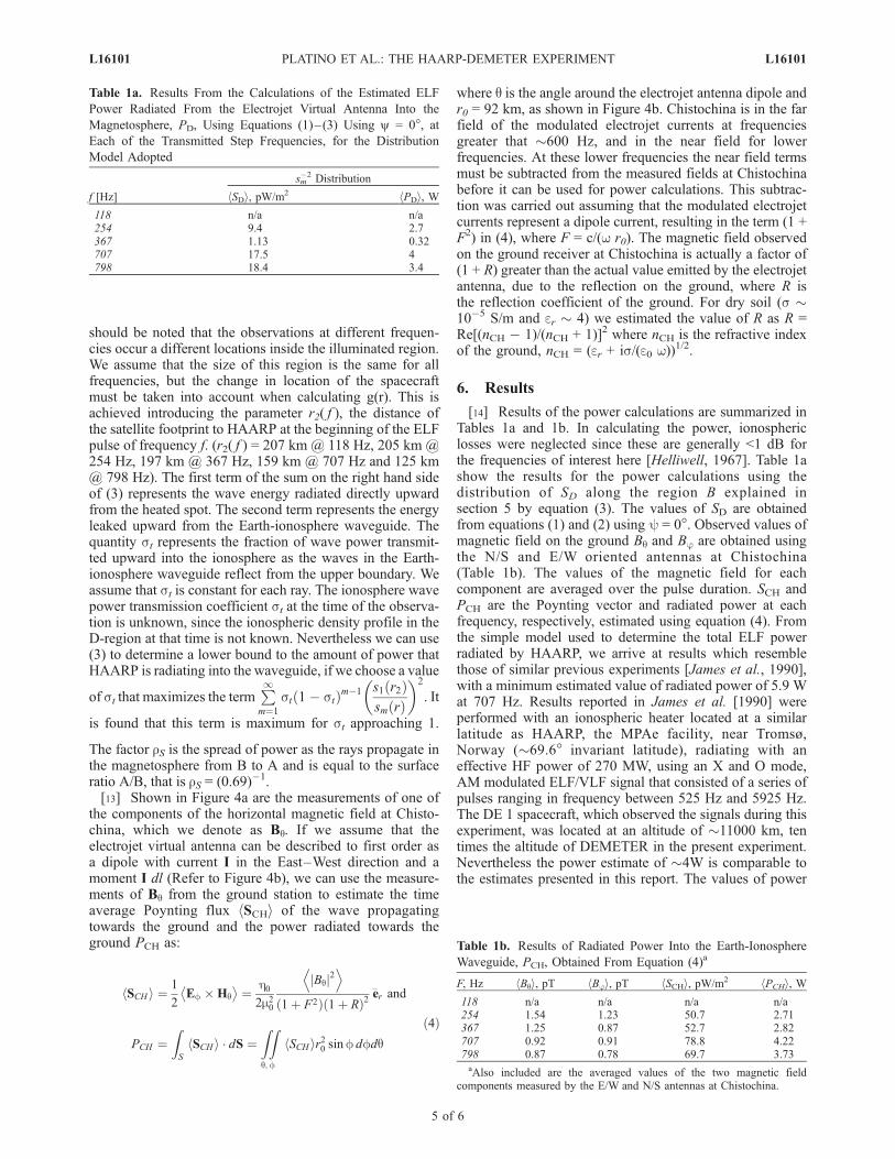
[8] ELF/VLF waves generated by HAARP – modulatedelectrojet currents were observed on one fourth of theDEMETER satellite passes over HAARP (3 times of 12passes). This low probability may be due to the variabilityof the intensity of the electrojet [Lefeuvre et al., 1985;James et al., 1984; Inan and Helliwell, 1985], as well as theambient ELF noise levels at the DEMETER orbit. Howeverwe also have to consider the fact that DEMETER does notrecord data above the invariant latitude of 65�, which, giventhe fact that HAARP is located at 62.4� and that the ELFraypaths have the tendency to move towards higher lat-itudes, may significantly limit the chances of observing theHAARP-generated ELF signal to those occasions when theemitted ELF fields are relatively intense.[9] Figure 3 shows an overview spectrogram of data
recorded using the ICE and IMSC instruments onDEMETER during February 10, 2005, where theHAARP-transmitted signal (Figure 1) is clearly observedduring a 30 second period. Pulses at all of the ELFmodulation frequencies are observed except the one at647 Hz and the ones above 800 Hz. Between 600 Hz and650 Hz, a strong noise band is seen which corresponds tothe local proton gyrofrequency, representing the upper bandlimit for left hand mode propagation. The 647 Hz signalfrom HAARP may be strongly absorbed (attenuated) due toits proximity to the upper cutoff since the 647 Hz signal is
observed on the ground at the same levels as the other ELFpulses. Pulses at frequencies higher than 800 Hz are notobserved because the DEMETER receiver stopped record-ing at 06:53:27 UT. These pulses were in fact also producedand launched downward, as evidenced by the fact that theyare observed on the ground. Similar pulses in this frequencyrange were actually detected on DEMETER during otherpasses, where the termination of the data recording (at the65-degree invariant latitude point) was at a later time in thecourse of the transmission sequence. It can be seen thatmany pulses exhibit deep fading, especially those at 707 Hzand 798 Hz. This fading is possibly due to multi–patheffects produced by ionospheric irregularities [Sonwalkar etal., 1984]. Natural impulsive emissions are observed in theelectric field instrument below 600 Hz. A resonance atthe proton gyrofrequency is observed between 600 Hz and650 Hz. Other artificial emissions are observed like contin-uous narrow band observed around 180 Hz, most likelyproduced by power line harmonics. The spectral linesobserved above 800 Hz and the narrow band noise observedbelow 50 Hz in the magnetic field instrument are due toinstrumental noise onboard the satellite.[10] Figure 4a shows simultaneous data recorded on the
ground near Chistochina, Alaska, at a distance of �36 kmfrom the HAARP HF heater. These data also show ELFsignals generated by HAARP. Displayed in this figure is thewave magnetic field detected with one of the two loopantennas on the ground. This type of data provides anindication of the strength of the ELF/VLF signal radiateddownward by the auroral-electrojet antenna. Since the extentof the generation region is believed to encompass the upper
Figure 3. Detailed ICE and IMSC spectrograms from theDEMETER satellite pass during February 10, 2005. (a) Anoverview of the detected HAARP signal in one of theelectric field components. The transmitted pattern atfrequencies up to 798 Hz is observed. (b) An overview ofthe detected HAARP signal in one of the magnetic fieldcomponents. The transmitted pattern at frequencies up to798 Hz is observed.
L16101 PLATINO ET AL.: THE HAARP-DEMETER EXPERIMENT L16101
3 of 6
boundary of the Earth-ionosphere waveguide, it is not clear asto whether efficient coupling of ELF wave energy upward (toDEMETER altitudes) is indicative of efficient coupling toground-based sites (and/or vice versa). The ELF radiationdirected upward from the heated spot into the magnetospheremay be significantly different from that directed into theEarth-ionosphere waveguide. Figure 4b shows a schematicof the heated region and illuminated region, with respect tothe ground receiver at Chistochina. The vector I representsthe electrojet current, while dl is a differential vector lengthalong I. Also plotted areHq and Ej the electric and magneticfield vectors observed at the ground receiver.
5. Calculation of the ELF Power Radiated byHAARP
[11] To estimate the total ELF power radiated as a resultof modulated HF heating by HAARP, we use the expressionbelow [Jasna Ristic-Djurovic, 1993, pp. 40–41] to calculatethe time average Poynting flux vector hSDi, using local coldplasma parameters (as measured on DEMETER) as well asthe value of the total wave magnetic field BD, for arbitraryvalues of wave normal angle y:
where h. . .i symbol denotes averaging in time over theduration of each ELF/VLF pulse, where:
r1 ¼ iEz
Ey
¼ n2 � Sð Þn2 siny cosyD n2 sin2 y� P� � r2 ¼ i
Ex
Ey
¼ n2 � Sð ÞD
and X ¼ P
P � n2 sin2 y� �
The refractive index n as well as the values of the auxiliaryvariables D, P, and S are obtained from Stix [1962, p. 10].These values depend on �e, �i, the electron and ion plasmafrequency and We, Wi, the electron and ion gyrofrequency aswell as the wave angular frequency w. The gyrofrequencyvalues are calculated using a DGRF/IGRF GeomagneticField model with B0 = 40.804 mT at the HAARP geographiccoordinates. The plasma frequency values are determinedfrom measurements onboard DEMETER of electron and ion(mostly O+) density using the Langmuir Probe Instrument(ISL) and the Plasma Analyzer Instrument (IAP), foran electron density of ne � 4750 cm�3 and an ion densityof ni � 5352 cm�3. The refractive index n also depends ony, the wave normal angle.[12] As shown in Figure 2, the HAARP-generated ELF
signal is observed on DEMETER at a distance for which thesubsatellite point on the ground is 430 km away fromHAARP. The signal is observed during a 30 second period,after which the DEMETER receiver is shut off. Thereforeour observations are representative of only the outer part ofthe illuminated region. In order to integrate SD over the totalarea and obtain an estimate for the radiated ELF power, wemust assume a model of the distribution of ELF wave powerover the illuminated area B. We assume that the variation ofSD is symmetrical around the magnetic field line intersect-ing HAARP and we define a function g(r) which representsthe radial variation of the Poynting vector with r, the radialperpendicular distance from the HAARP magnetic field line.
the total ray path from the heated region to the injection pointin the ionosphere at a radial distance r, for a ray reflecting mtimes in the Earth-ionosphere waveguide, highlighted ingreen in Figure 2 for m = 1. Assuming that the power variesas sm
�2, were s is the distance to the source, the radiated powerPD is:
PD ¼ZB
hSDi � dS ¼ hSDiZr;
Zf
g rð Þr dr df
¼ hSDi"rS
Zr10
2p r dr þ rSX1m¼1
Zr20
2p rst 1� stð Þm�1
� s1 r2 fð Þð Þsm rð Þ
�2
dr
#ð3Þ
where j is the angle around the HAARP magnetic field line,the radial distance from the r1 is the radius of the illumi-nated region C, (r1 � 21 km). It should be noted that duringthe 30 seconds of observation of the HAARP signal,DEMETER moves a distance of approximately 6.7 km/sec30 sec = 200 km over the illuminated region. Therefore it
Figure 4. (a) Ground observations of the ELF HAARPgenerated signal at Chistochina, on February 10, 2005,starting at 06:52:30 UT. The panel shows data from avertical magnetic loop antenna, oriented to the geographicEast-West line. The magnitude scale refers to magnetic fieldintensity in pT / Hz�1/2. (b) Scheme used for the calculationof the radiated power toward the ground. Indicated are theelectrojet currents, moving outside the page, and thelocation of the HAARP heater, as well as the receiver inChistochina.
ð2Þ
L16101 PLATINO ET AL.: THE HAARP-DEMETER EXPERIMENT L16101
4 of 6
should be noted that the observations at different frequen-cies occur a different locations inside the illuminated region.We assume that the size of this region is the same for allfrequencies, but the change in location of the spacecraftmust be taken into account when calculating g(r). This isachieved introducing the parameter r2( f ), the distance ofthe satellite footprint to HAARP at the beginning of the ELFpulse of frequency f. (r2( f ) = 207 km @ 118 Hz, 205 km @254 Hz, 197 km @ 367 Hz, 159 km @ 707 Hz and 125 km@ 798 Hz). The first term of the sum on the right hand sideof (3) represents the wave energy radiated directly upwardfrom the heated spot. The second term represents the energyleaked upward from the Earth-ionosphere waveguide. Thequantity st represents the fraction of wave power transmit-ted upward into the ionosphere as the waves in the Earth-ionosphere waveguide reflect from the upper boundary. Weassume that st is constant for each ray. The ionosphere wavepower transmission coefficient st at the time of the observa-tion is unknown, since the ionospheric density profile in theD-region at that time is not known. Nevertheless we can use(3) to determine a lower bound to the amount of power thatHAARP is radiating into the waveguide, if we choose a value
of st that maximizes the termP1m¼1
st 1� stð Þm�1 s1 r2ð Þsm rð Þ
�2
. It
is found that this term is maximum for st approaching 1.
The factor rS is the spread of power as the rays propagate inthe magnetosphere from B to A and is equal to the surfaceratio A/B, that is rS = (0.69)�1.[13] Shown in Figure 4a are the measurements of one of
the components of the horizontal magnetic field at Chisto-china, which we denote as Bq. If we assume that theelectrojet virtual antenna can be described to first order asa dipole with current I in the East–West direction and amoment I dl (Refer to Figure 4b), we can use the measure-ments of Bq from the ground station to estimate the timeaverage Poynting flux hSCHi of the wave propagatingtowards the ground and the power radiated towards theground PCH as:
SCHh i ¼ 1
2Ef �Hq� �
¼ h02m20
Bqj j2D E
1þ F2ð Þ 1þ Rð Þ2^er and
PCH ¼ZS
SCHh i � dS ¼Zq;
Zf
hSCH ir20 sinf dfdq
where q is the angle around the electrojet antenna dipole andr0 = 92 km, as shown in Figure 4b. Chistochina is in the farfield of the modulated electrojet currents at frequenciesgreater that �600 Hz, and in the near field for lowerfrequencies. At these lower frequencies the near field termsmust be subtracted from the measured fields at Chistochinabefore it can be used for power calculations. This subtrac-tion was carried out assuming that the modulated electrojetcurrents represent a dipole current, resulting in the term (1 +F2) in (4), where F = c/(w r0). The magnetic field observedon the ground receiver at Chistochina is actually a factor of(1 + R) greater than the actual value emitted by the electrojetantenna, due to the reflection on the ground, where R isthe reflection coefficient of the ground. For dry soil (s �10�5 S/m and er � 4) we estimated the value of R as R =Re[(nCH � 1)/(nCH + 1)]2 where nCH is the refractive indexof the ground, nCH = (er + is/(e0 w))
1/2.
6. Results
[14] Results of the power calculations are summarized inTables 1a and 1b. In calculating the power, ionosphericlosses were neglected since these are generally <1 dB forthe frequencies of interest here [Helliwell, 1967]. Table 1ashow the results for the power calculations using thedistribution of SD along the region B explained insection 5 by equation (3). The values of SD are obtainedfrom equations (1) and (2) using y = 0�. Observed values ofmagnetic field on the ground Bq and Bj are obtained usingthe N/S and E/W oriented antennas at Chistochina(Table 1b). The values of the magnetic field for eachcomponent are averaged over the pulse duration. SCH andPCH are the Poynting vector and radiated power at eachfrequency, respectively, estimated using equation (4). Fromthe simple model used to determine the total ELF powerradiated by HAARP, we arrive at results which resemblethose of similar previous experiments [James et al., 1990],with a minimum estimated value of radiated power of 5.9 Wat 707 Hz. Results reported in James et al. [1990] wereperformed with an ionospheric heater located at a similarlatitude as HAARP, the MPAe facility, near Tromsø,Norway (�69.6� invariant latitude), radiating with aneffective HF power of 270 MW, using an X and O mode,AM modulated ELF/VLF signal that consisted of a series ofpulses ranging in frequency between 525 Hz and 5925 Hz.The DE 1 spacecraft, which observed the signals during thisexperiment, was located at an altitude of �11000 km, tentimes the altitude of DEMETER in the present experiment.Nevertheless the power estimate of �4W is comparable tothe estimates presented in this report. The values of power
Table 1a. Results From the Calculations of the Estimated ELF
Power Radiated From the Electrojet Virtual Antenna Into the
Magnetosphere, PD, Using Equations (1)–(3) Using y = 0�, atEach of the Transmitted Step Frequencies, for the Distribution
Table 1b. Results of Radiated Power Into the Earth-Ionosphere
Waveguide, PCH, Obtained From Equation (4)a
F, Hz hBqi, pT hBji, pT hSCHi, pW/m2 hPCHi, W118 n/a n/a n/a n/a254 1.54 1.23 50.7 2.71367 1.25 0.87 52.7 2.82707 0.92 0.91 78.8 4.22798 0.87 0.78 69.7 3.73aAlso included are the averaged values of the two magnetic field
components measured by the E/W and N/S antennas at Chistochina.
ð4Þ
L16101 PLATINO ET AL.: THE HAARP-DEMETER EXPERIMENT L16101
5 of 6
estimated using DEMETER wave amplitudes are generallylower than the estimated power based on ground observa-tions. In particular, the power estimated using DEMETER at367 Hz and 647 Hz, reveals a strong attenuation that is notobserved on the ground receiver. The pulses at frequenciesbelow the local proton gyrofrequency are subject to modeconversion from the right handed to the left handed mode,which may be affecting the pulses at 647 Hz and 367 Hz. Itcan be seen that there is a modest frequency dependence ofthe radiated power, which can be interpreted as an increasewith frequency of the efficiency of the generation of ELFwaves by modulation of the electrojet (in space: James et al.[1984], on the ground: Rietveld et al. [1989]). However thisdependence is less than the f2 dependence which would beexpected from a dipole antenna of fixed length in free space.
[15] Acknowledgments. This work was supported, in part, by theHigh Frequency Active Auroral Research Program (HAARP), under grantN00014-03-0631 from the Office of Naval Research (ONR). We thank J. J.Berthelier for providing the ICE and IAP data. We also thank M. J.McCarrick for setting up the transmissions schedule and time-frequencypatterns in the HAARP HF heater and P. A. Kossey for the support in thisexperiment.
ReferencesBell, T. F., U. S. Inan,M. Platino, J. S. Pickett, P. A.Kossey, andE. J. Kennedy(2004), CLUSTER observations of lower hybrid waves excited at highaltitudes by electromagnetic whistler mode signals from the HAARPfacility, Geophys. Res. Lett., 31, L06811, doi:10.1029/2003GL018855.
Helliwell, R. A. (1967), A theory of discrete VLF emissions from themagnetosphere, J. Geophys. Res., 72(19), 4773–4790.
Helliwell, R. A., J. P. Katsufrakis, T. F. Bell, and R. Raghuram (1975), VLFline radiation in the Earth’s magnetosphere and its association with powersystem radiation, J. Geophys. Res., 80, 4249–4258.
Inan, U. S., and T. F. Bell (1977), The Plasmapause as a VLF wave guide,J. Geophys. Res., 82, 2819–2827.
Inan, U. S., and R. A. Helliwell (1985), Active experiments from ground, inResults of the Arcad 3 Project and of Recent Programmes in Magneto-spheric and Ionospheric Physics Toulouse, vol. 84, pp. 599– 607,Cepadues-Ed., Toulouse, France.
Inan, U. S., M. Golkowski, D. L. Carpenter, N. Reddell, R. C. Moore, T. F.Bell, E. Paschal, P. Kossey, E. Kennedy, and S. Z. Meth (2004), Multi-hop whistler-mode ELF/VLF signals and triggered emissions excited bythe HAARP HF heater, Geophys. Res. Lett., 31, L24805, doi:10.1029/2004GL021647.
James, H. G., R. L. Dowden, P. Rietveld, P. Stubbe, and H. Kopka (1984),Simultaneous observations of ELF waves from an artificially modulated
auroral electrojet in space and on the ground, J. Geophys. Res., 89,1655–1666.
James, H. G., U. S. Inan, and M. T. Rietveld (1990), Observations on theDE 1 spacecraft of ELF/VLF waves generated by an ionospheric heater,J. Geophys. Res., 95, 12,187–12,195.
Jasna Ristic-Djurovic, L. (1993), Gyroresonant scattering of radiation beltelectrons by oblique whistler waves, Ph.D. thesis, Dep. of Electr. Eng.,Stanford Univ., Stanford, Calif.
Kapustin, I. N., R. A. Pertsovsky, A. N. Vasil’ev, V. S. Smirnov, O. M.Raspopov, L. E. Solov’eva, A. A. Ul’yachenko, A. A. Arykov, andN. V. Galakhova (1977), Generation of radiation at combination fre-quencies in the region of the auroral electrojet, JETP Lett., 25(5),248–251.
Lefeuvre, F., J. L. Rauch, V. I. Dee, E. E. Titova, and V. E. Yurov (1985),Detection from Aureol-3 of the modulation of auroral electrojet by HF-heating from ELF signals in the upper atmosphere above Tromsoe, inResults of the Arcad 3 Project and of Recent Programmes in Magneto-spheric and Ionospheric Physics Toulouse, vol. 84, pp. 609 –619,Cepadues-Ed., Toulouse, France.
Parrot, M. (2002), The micro-satellite DEMETER, J. Geodyn., 33(4–5),535–541.
Platino, M., U. S. Inan, T. F. Bell, J. S. Pickett, E. J. Kennedy, J. G.Trotignon, J. L. Rauch, and P. Canu (2004), Cluster observations ofELF/VLF signals generated by modulated heating of the lower iono-sphere with the HAARP HF transmitter, Ann. Geophys., 22(7), 2643–2653.
Rietveld, M. T., P. Stubbe, and H. Kopka (1989), On the frequency depen-dence of ELF/VLF waves produced by modulated ionospheric heating,Radio Sci., 24, 270–278.
Sonwalkar, V. S., T. F. Bell, R. A. Helliwell, and U. S. Inan (1984), Directmultiple path magnetospheric propagation: A fundamental property ofnonducted VLF waves, J. Geophys. Res., 89, 2823–2830.
Stix, T. H. (1962), The Theory of Plasma Waves, McGraw-Hill, New York.Stubbe, P., and H. Kopka (1977), Modulation of the polar electrojet bypowerful HF waves, J. Geophys. Res., 82, 2319–2325.
Stubbe, P., H. Kopka, and R. L. Dowden (1981), Generation of ELF andVLF waves by polar electrojet modulation: Experimental results, J. Geo-phys. Res., 86, 9073–9078.
Stubbe, P., H. Kopka, M. T. Rietveld, and R. L. Dowden (1982), ELF andVLF wave generation by modulated heating of the current carrying of thelower ionosphere, J. Atmos. Terr. Phys., 44, 1123–1125.
�����������������������T. F. Bell, U. S. Inan, and M. Platino, Space, Telecommunications and
Radioscience (STAR) Laboratory, Stanford University, Stanford, CA94305, USA. ([email protected])E. J. Kennedy, Naval Research Laboratory, 4555 Overlook Avenue SW,
Washington, DC 20375, USA.M. Parrot, Laboratoire de Physique et Chimie de l’Environnement,
Centre National de la Recherche Scientifique, 3 A avenue de la RechercheScientifique, F-45071 Orleans cedex 02, France.
L16101 PLATINO ET AL.: THE HAARP-DEMETER EXPERIMENT L16101