DEMO VERSION OF THE SECOND ROUND TASKS 1 Engineering & Technology Sample test Task 1 (2 points) A wheel rotates on an axis according to the law: () = 2 2 (rad). Find its angular velocity at t = 0.5 (s). Solution: = () = 4 =2 rad/s Answer: 2 rad/s Task 2 (4 points) A force F = 10 N was applied to the upper part of a pipe on a horizontal plane. The pipe has inner diameter d = 0.1 m, outer diameter D = 0.2 m and mass m = 40 kg. Calculate the angular acceleration of the pipe. There is no slipping between the pipe and the surface. Express the result in (rad/s 2 ), rounded to an integer. Solution: The theorem of angular momentum change holds: = where is the external torque. The torques at the point of contact between the pipe and the surface will be: = = 0 where the moment of inertia of the pipe is determined by the expression:
Transcript
DEMO VERSION OF THE SECOND ROUND TASKS
1
Engineering & Technology
Sample test
Task 1 (2 points)
A wheel rotates on an axis according to the law:
𝜑(𝑡) = 2𝑡2(rad).
Find its angular velocity at t = 0.5 (s).
Solution:
𝜔 =𝑑𝜑(𝑡)
𝑑𝑡= 4𝑡=2 rad/s
Answer: 2 rad/s
Task 2 (4 points)
A force F = 10 N was applied to the upper part of a pipe on a horizontal plane. The
pipe has inner diameter d = 0.1 m, outer diameter D = 0.2 m and mass m = 40 kg.
Calculate the angular acceleration of the pipe. There is no slipping between the pipe
and the surface. Express the result in (rad/s2), rounded to an integer.
Solution:
The theorem of angular momentum change holds: 𝑑𝐿
𝑑𝑡= 𝑀𝐸
where 𝑀𝐸 is the external torque.
The torques at the point of contact between the pipe and the surface will be:
𝑀𝐸 = 𝐹𝐷 = 𝐼0𝜀 where the moment of inertia of the pipe is determined by the expression:
DEMO VERSION OF THE SECOND ROUND TASKS
2
𝐼0 =1
8𝑚(3𝐷2 + 𝑑2)
Thus, the angular acceleration is:
𝜀 =8𝐹𝐷
𝑚(3𝐷2 + 𝑑2)= 3(𝑟𝑎𝑑 𝑠2⁄ )
Task 3 (11 points)
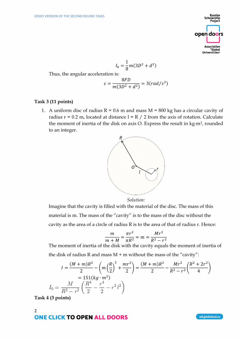
1. A uniform disc of radius R = 0.6 m and mass M = 800 kg has a circular cavity of
radius r = 0.2 m, located at distance l = R / 2 from the axis of rotation. Calculate
the moment of inertia of the disk on axis O. Express the result in kg∙m2, rounded
to an integer.
Solution:
Imagine that the cavity is filled with the material of the disc. The mass of this
material is m. The mass of the “cavity” is to the mass of the disc without the
cavity as the area of a circle of radius R is to the area of that of radius r. Hence:
𝑚
𝑚 +𝑀=𝜋𝑟2
𝜋𝑅2= 𝑚 =
𝑀𝑟2
𝑅2 − 𝑟2
The moment of inertia of the disk with the cavity equals the moment of inertia of
the disk of radius R and mass M + m without the mass of the “cavity”:
𝐼 =(𝑀 +𝑚)𝑅2
2− (𝑚(
𝑅
2)2
+𝑚𝑟2
2) =
(𝑀 +𝑚)𝑅2
2−
𝑀𝑟2
𝑅2 − 𝑟2(𝑅2 + 2𝑟2
4)
= 151(𝑘𝑔 ∙ 𝑚2)
Task 4 (3 points)
DEMO VERSION OF THE SECOND ROUND TASKS
3
In which figure is ∆ ABC perpendicular to the horizontal plane of the projections?
Answer: 1.
Task 5 (3 points)
What is line AC drawn in the plane defined by
intersecting lines ∑ (AB, CD) called?
1. horizontal
2. frontal
3. profile line
4. the line of greatest slope
Task 6 (10 points) Draw threaded connections
Draw the attachment of a lens to a mount with a threaded ring. Make an assembly drawing with a front section in place of the front view. Base the drawing on the 3D model of the assembly connection.
DEMO VERSION OF THE SECOND ROUND TASKS
4
Solution:
Task 7 (2 points)
A bar with a constant cross section of area F = 20 cm2, whose left edge is rigidly
fixed in section A, is loaded by concentrated forces P and 3P in sections B and C
respectively (P = 10 kN). Determine the maximum modulo value of normal stresses σхmax
in these sections.
a a a
3P
F
A B C D
P
DEMO VERSION OF THE SECOND ROUND TASKS
5
Solution
1. Reactions RA and RD will occur in supports A and D. We can mark them on a force
diagram.
According to the equilibrium equation:
ΣХ=0 => RA – P + 2P – RD = 0, т.е. RA = RD – P.
2. The beam is statically indeterminate because there are four unknown forces. If
support D is dropped, reaction RD will be considered as an external force. The
additional equation UX (D) = 0 will be:
– 𝑃·2𝑎
𝐹·𝐸 +
2𝑃·3𝑎
𝐹·𝐸–𝑅𝐷·4𝑎
𝐹·𝐸= 0 => RD = P, RA = 0.
3. To calculate axial forces Nx in the sections, we use the section method
Section 1:
ΣХ=0 => RA+ Nx1=0, Nx1= – RA =0.
Section 2:
ΣХ=0 => RA – P+Nx2=0, Nx2 = P= 10 kN.
Section 3:
2P RD
1A
2A
3A
P RA
X
Nx1
RA
X
Nx2
P RA
X
2P P RA
X Nx3
DEMO VERSION OF THE SECOND ROUND TASKS
6
ΣХ=0 => RA – P + 2P + Nx3 = 0, Nx3 = – P = –10 kN.
4. The maximum value (modulo) of axial force Nx in the force sections is 10 kN.
Since the cross section of the bar is constant, the maximum modulo value of the normal
stress is:
𝜎𝑚𝑎𝑥 =|𝑁𝑥|
𝐹 = 10 kN /20cm2=15 MPa
Answer: 15 MPa.
Task 8 (4 points)
Beam ОС is suspended on rods 1, 2, 3 made of a material with Young's modulus E. The rods have cross-sectional areas F1, F2 and F3 respectively; the length of the rods is а. The distance from the joint and between the rods is also а. The beam is considered a rigid body compared to the rods. The left end of the beam is attached to a rigid wall at point O with a hinged connection. At point C, it is loaded with force P. The weight of the beam is neglected compared to the force P. P = 14 kN, F1=F2=F3=F.
Determine the value of axial force N1 in rod 1. Give the answer in (kN), rounded to an integer.
Solution:
Since the beam is in equilibrium under load, we can cut it out along the rods near
the beam and obtain an equilibrium equation, assuming that all the rods experience
tension.
Σ Mo= 0 => N1·a + N2·2a + N3·3a = P·3a (1)
DEMO VERSION OF THE SECOND ROUND TASKS
7
Then we build a deformed system. Beam ОС will rotate on hinge O under force P.
The amount of rotation of the beam is determined by the deformations of rods 1, 2 and 3.
Due to the insignificance of deformations, we can assume that any point of the beam
moves vertically downward.
In the figure, ОС’ demonstrates the position of the beam without load and ОС
shows that under load Р. Accordingly, АА’ is the elongation of rod 1; ВВ’, of rod 2; СС’,
of 3. Now we can write down the geometric similarity of the elongation of the rods.
Δl2 = 2Δl1 и Δl3 = 3Δl1 (2)
Then we express the elongation of rods through forces, lengths, and stiffness.
Δl1 = N1·a / EF
Δl2 = N2·a / EF (3)
Δl3 = N3·a / EF
By replacing expressions for extensions (3) in (2), we obtain:
N2 = 2 N1 и N3 = 3 N1 (4)
Next, we substitute expression (4) into (1)
N1 = 3
14⋅ 𝑃 N2 =
6
14⋅ 𝑃 N3 =
9
14⋅ 𝑃 (5)
By substituting the load value P = 14 kN, we get the amount of force in rod 1: N1
= 3 kN.
Answer: 3 Task 9 (11 points)
A symmetric system of three rods 1, 2 and 3 made from a material with Young's
modulus E has cross-sectional areas F1, F2, and F3 respectively. The length of vertical rod
DEMO VERSION OF THE SECOND ROUND TASKS
8
2 is L. The angles between the rods are the same and equal to φ. The upper ends of the
rods are attached to a rigid wall with a hinged connection, whilst the lower ends are
similarly attached at point A, to which vertical force P is applied. P = 10 kN, F1 = F2 = F3
= F, cos φ = 0.7.
Calculate force N1 in rod 1.
Solution:
Since the system of rods under load P is in equilibrium, we can cut the rods near
node A and obtain equilibrium equations, assuming that all the rods experience tension.
Σ X = 0 => −N1 ·sinφ + N3·sinφ = 0,
and N1 = N3 since the system is symmetrical.
Σ Y = 0 => −P + N1 ·cosφ + N2 + N3·cosφ = 0,
if N1 = N3 , −P + 2N1 ·cosφ + N2 = 0 (1)
DEMO VERSION OF THE SECOND ROUND TASKS
9
Then we build a deformed system. Under force P, the node moves from position
A' to A. The amount of movement of the node is determined by the deformations of rods
1, 2 and 3. Due to the insignificance of the deformations, we can assume that angle φ
between the rods does not change.
So, A’A will be the extension of rod 2; AB, of rod 1; AC, of rod 3. The relation
between the sides of the right triangle A’AB will be:
Δl1 = Δ l2 ·cosφ (2)
Then, we express the elongation of rods 1 and 2 in terms of
forces, lengths, and stiffness to obtain
Δl1 = N1·l /EF cosφ и Δl2 = N2·l /EF (3)
By substituting expressions for extensions (3) into (2), we get
N2 = N1 / cos 2φ (4)
Next, we substitute expression (4) into (1) and get
N1 = P· cos 2φ /(1 + 2 cos 3φ) и N2 = P / (1 + 2 cos 3φ)
(5)
Substituting the value of load P = 10 kN, cos φ = 0.7, we obtain the amount of
force in rod 1.
N1 = 10·0.49 / 1.686 = 2.90 kN
Answer: 2.90 kN Task 10 (2 points) Mechanical properties of materials (evaluating the hardness of materials)
Find the Vickers hardness number if an applied load of 2.5 kgf leaves an
indentation with an average diagonal of 0.389 mm.
Solution
DEMO VERSION OF THE SECOND ROUND TASKS
10
The Vickers hardness test focuses on the relationship between the depth of penetration of a tetrahedral diamond pyramid (indenter) with a face angle of 136° into the material and the amount of applied force. The surface hardness of the test material can be determined using the formula:
HV = 1.8544 P/d2, kgf/mm2 or hardness units,
where P is the load on the indenter, kgf, d is the average value of indentation diagonals, mm.
We substitute the given values of load applied to the indenter and the average
value of the indentation diagonals into formula (1):
Calculate the carbon content in steel needed to obtain a material with martensite
hardness HRCM = 33. What percentage of the area will be occupied by ferrite in the microstructure analysis of the initial material?
Solution:
During quenching, the hardness of steel increases as a martensitic structure is formed. Although the hardness of martensite depends on many parameters, the carbon content in steel is the most influential factor. To determine the carbon content in an alloy by the hardness of the resulting martensite after quenching, we can use the following empirical formula. (It is applied when calculating the carbon content in steels with martensite hardness in the range of 30-65HRCM.)