DemoPad Design Software Manual DemoDesign Software Manual INTRODUCTION WHAT IS THE DEMOPAD SOLUTION? SYSTEM REQUIREMENTS GETTING STARTED OBTAINING & INSTALLING THE SOFTWARE INSTALLATION CREATING A NEW PROJECT APPLICATION WINDOW ELEMENTS OBTAINING THE DEMOCONTROLHD APP PROJECT FILE MANAGEMENT BASIC CONCEPTS DEVICES PAGES PAGE OBJECTS ACTIONS FLAGS LABELS NUMBERS
Transcript
DemoPad Design Software Manual
DemoDesign Software Manual
INTRODUCTION WHAT IS THE DEMOPAD SOLUTION?
SYSTEM REQUIREMENTS
GETTING STARTED OBTAINING & INSTALLING THE SOFTWARE
INSTALLATION
CREATING A NEW PROJECT
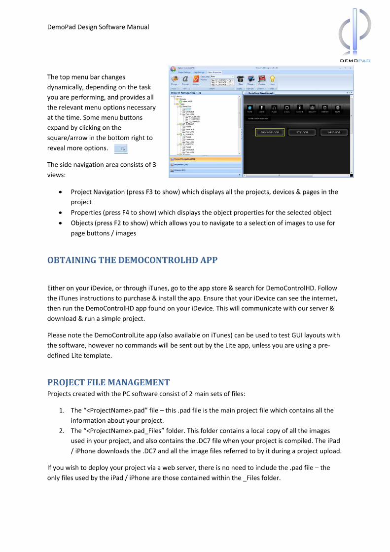
APPLICATION WINDOW ELEMENTS
OBTAINING THE DEMOCONTROLHD APP
PROJECT FILE MANAGEMENT
BASIC CONCEPTS DEVICES
PAGES
PAGE OBJECTS
ACTIONS
FLAGS
LABELS
NUMBERS
DemoPad Design Software Manual
GETTING SUPPORT
COMPATIBLE HARDWARE TCP/IP DEVICES
UDP DEVICES
COMPATIBLE SYSTEMS (2-WAY FEEDBACK)
ORGANISING YOUR PROJECT GUI DESIGN CONCEPTS
CONTROLLABLE EQUIMENT
DEVICES
COMMANDS
USING CUSTOM GRAPHICS
PROJECT DEVELOPMENT CYCLE
CREATING THE USER INTERFACE ADDING PAGES TO A PROJECT
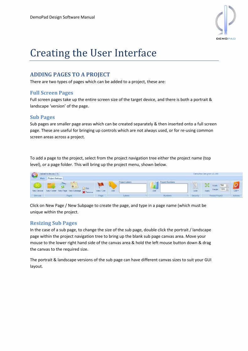
SETTING A PAGE BACKGROUND IMAGE / COLOR
ORGANISING PAGES WITH FOLDERS
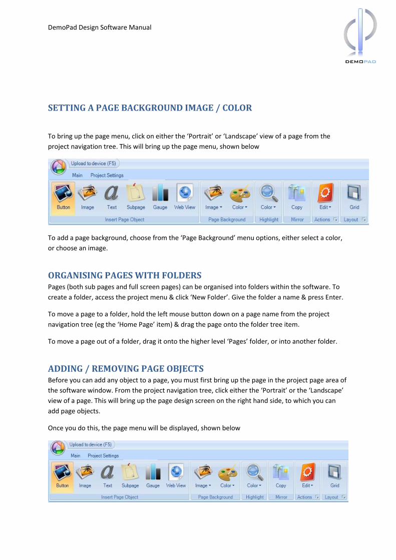
ADDING / REMOVING PAGE OBJECTS
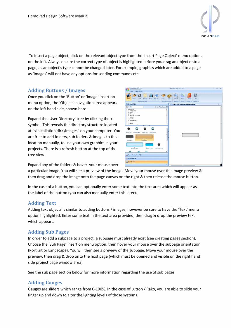
ADDING BUTTONS / IMAGES
ADDING TEXT
ADDING SUB PAGES
ADDING GAUGES
DemoPad Design Software Manual
ADDING WEB VIEWS
REMOVING OBJECTS
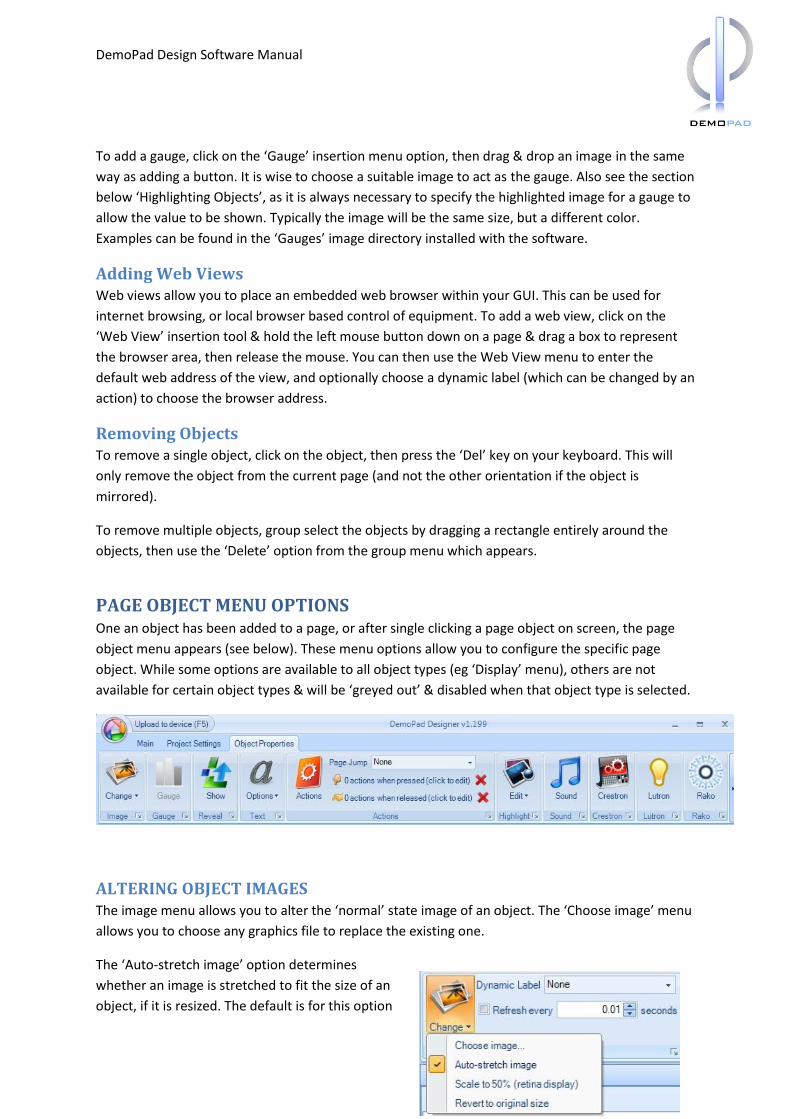
PAGE OBJECT MENU OPTIONS
ALTERING OBJECT IMAGES
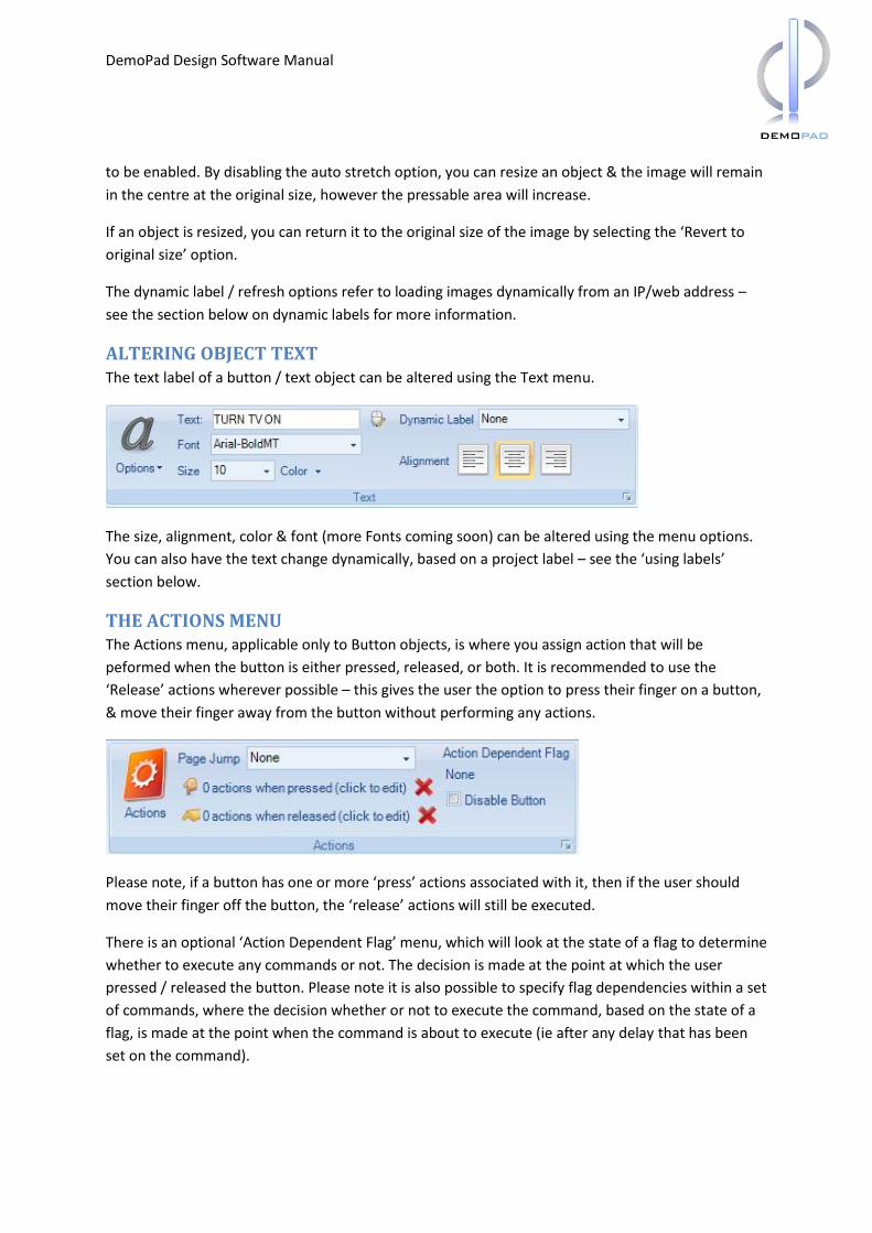
ALTERING OBJECT TEXT
THE ACTIONS MENU
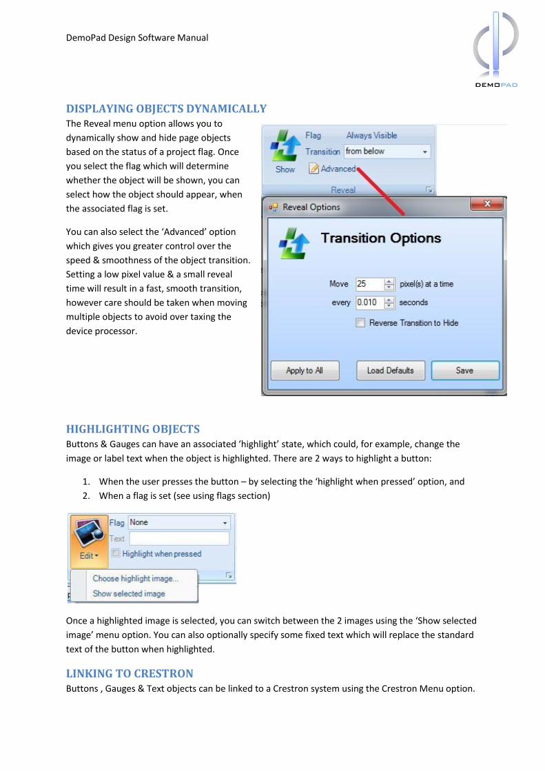
DISPLAYING OBJECTS DYNAMICALLY
HIGHLIGHTING OBJECTS
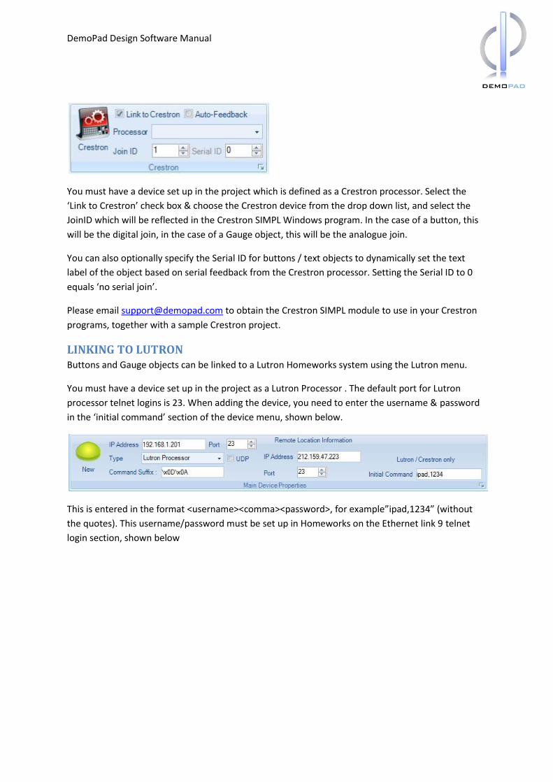
LINKING TO CRESTRON
LINKING TO LUTRON
LINKING TO RAKO
GROUPING / ALIGNING OBJECTS
MIRRORING OBJECTS
USING SUB PAGES
USING MERGED PAGES
SENDING COMMANDS ADDING A DEVICE TO A PROJECT
ENTERING OR IMPORTING COMMANDS
SENDING HEX COMMANDS
ASSIGNING COMMANDS TO BUTTON ACTIONS
DEPLOYING AND RUNNING THE PROJECT DEMOCONTROLHD SETTINGS
ZOOMING IN ON THE APP GUI
DemoPad Design Software Manual
ADVANCED TOPICS USING FLAGS
USING LABELS
USING NUMBERS
DYNAMICALLY LOADING IMAGES FROM THE WEB / IP CAMERAS
IMPLEMENTING A TOGGLE BUTTON
LAUNCHING OTHER APPS
SENDING DATA TO WEB SERVERS
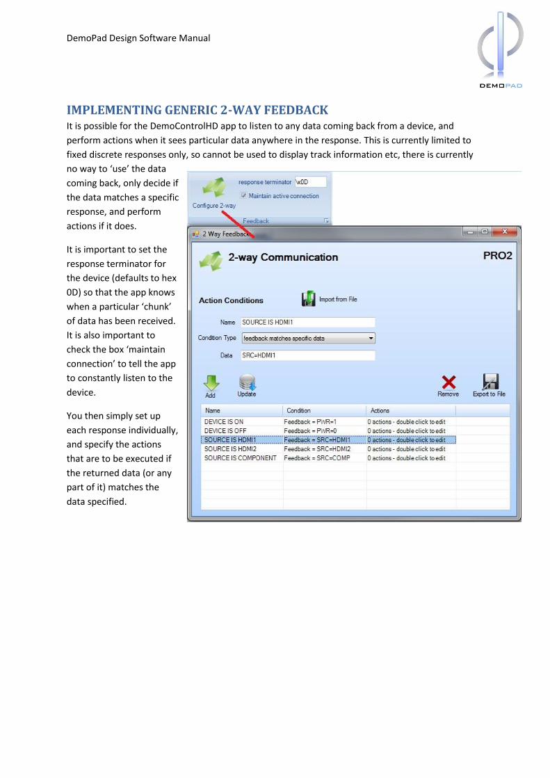
IMPLEMENTING GENERIC 2-WAY FEEDBACK
FURTHER INFORMATION
DemoPad Design Software Manual
Introduction
WHAT IS THE DEMOPAD SOLUTION?
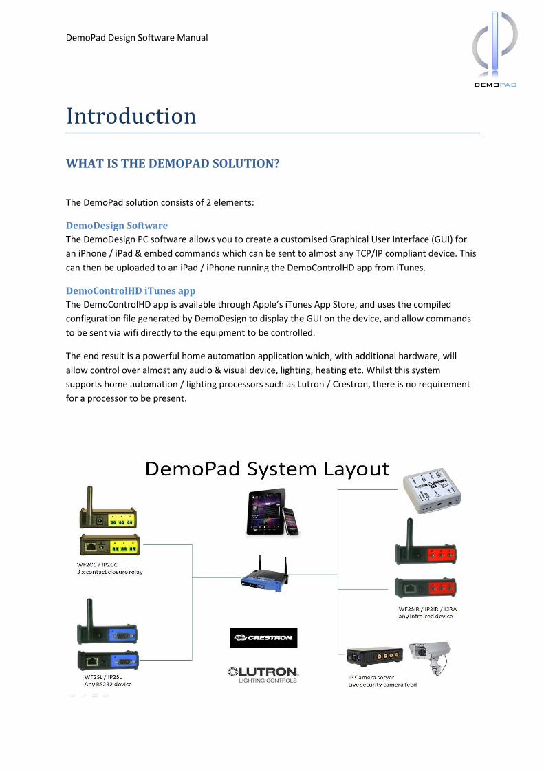
The DemoPad solution consists of 2 elements:
DemoDesign Software
The DemoDesign PC software allows you to create a customised Graphical User Interface (GUI) for
an iPhone / iPad & embed commands which can be sent to almost any TCP/IP compliant device. This
can then be uploaded to an iPad / iPhone running the DemoControlHD app from iTunes.
DemoControlHD iTunes app
The DemoControlHD app is available through Apple’s iTunes App Store, and uses the compiled
configuration file generated by DemoDesign to display the GUI on the device, and allow commands
to be sent via wifi directly to the equipment to be controlled.
The end result is a powerful home automation application which, with additional hardware, will
allow control over almost any audio & visual device, lighting, heating etc. Whilst this system
supports home automation / lighting processors such as Lutron / Crestron, there is no requirement
for a processor to be present.
DemoPad Design Software Manual
SYSTEM REQUIREMENTS
For Design Software: PC running Microsoft Windows OS (or emulator) – XP or later with .NET 3.5
installed. It is also recommended that the computer be fully updated with the latest Microsoft
updates – refer to your PC documentation.
For DemoControlHD app: iPhone / iPad / iPod Touch running iOS version 3.1.3 or later (iOS 4 or
later recommended)
DemoPad Design Software Manual
Getting Started
OBTAINING & INSTALLING THE SOFTWARE
The DemoDesign software can be downloaded from www.demopad.com/software.asp
INSTALLATION To install the software, double click on DemoDesignerSetup.msi & follow the onscreen instructions.
It is recommended to install the software to the default location of “c:\Program Files\Demopad
Software Ltd\Demopad Designer” which will henceforth be referred to as <program dir>.
Once installed, there should be an entry in the start menu under programs\Demopad, and a shortcut
icon on the desktop called “DemoPad Designer”. Double click the shortcut to launch the software.
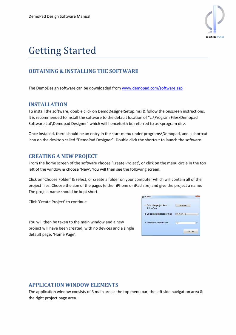
CREATING A NEW PROJECT From the home screen of the software choose ‘Create Project’, or click on the menu circle in the top
left of the window & choose ‘New’. You will then see the following screen:
Click on ‘Choose Folder’ & select, or create a folder on your computer which will contain all of the
project files. Choose the size of the pages (either iPhone or iPad size) and give the project a name.
The project name should be kept short.
Click ‘Create Project’ to continue.
You will then be taken to the main window and a new
project will have been created, with no devices and a single
default page, ‘Home Page’.
APPLICATION WINDOW ELEMENTS The application window consists of 3 main areas: the top menu bar, the left side navigation area &
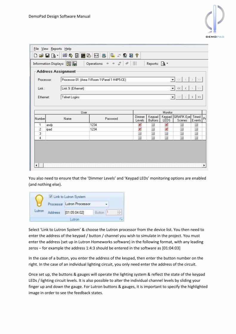
You also need to ensure that the ‘Dimmer Levels’ and ‘Keypad LEDs’ monitoring options are enabled
(and nothing else).
Select ‘Link to Lutron System’ & choose the Lutron processor from the device list. You then need to
enter the address of the keypad / button / channel you wish to simulate in the project. You must
enter the address (set up in Lutron Homeworks software) in the following format, with any leading
zeros – for example the address 1:4:3 should be entered in the software as [01:04:03]
In the case of a button, you enter the address of the keypad, then enter the button number on the
right. In the case of an individual lighting circuit, you only need enter the address of the circuit.
Once set up, the buttons & gauges will operate the lighting system & reflect the state of the keypad
LEDs / lighting circuit levels. It is also possible to alter the individual channel levels by sliding your
finger up and down the gauge. For Lutron buttons & gauges, it is important to specify the highlighted
image in order to see the feedback states.
DemoPad Design Software Manual
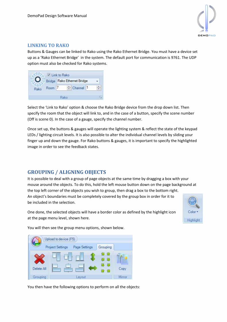
LINKING TO RAKO Buttons & Gauges can be linked to Rako using the Rako Ethernet Bridge. You must have a device set
up as a ‘Rako Ethernet Bridge’ in the system. The default port for communication is 9761. The UDP
option must also be checked for Rako systems.
Select the ‘Link to Rako’ option & choose the Rako Bridge device from the drop down list. Then
specify the room that the object will link to, and in the case of a button, specify the scene number
(Off is scene 0). In the case of a gauge, specify the channel number.
Once set up, the buttons & gauges will operate the lighting system & reflect the state of the keypad
LEDs / lighting circuit levels. It is also possible to alter the individual channel levels by sliding your
finger up and down the gauge. For Rako buttons & gauges, it is important to specify the highlighted
image in order to see the feedback states.
GROUPING / ALIGNING OBJECTS It is possible to deal with a group of page objects at the same time by dragging a box with your
mouse around the objects. To do this, hold the left mouse button down on the page background at
the top left corner of the objects you wish to group, then drag a box to the bottom right.
An object’s boundaries must be completely covered by the group box in order for it to
be included in the selection.
One done, the selected objects will have a border color as defined by the highlight icon
at the page menu level, shown here.
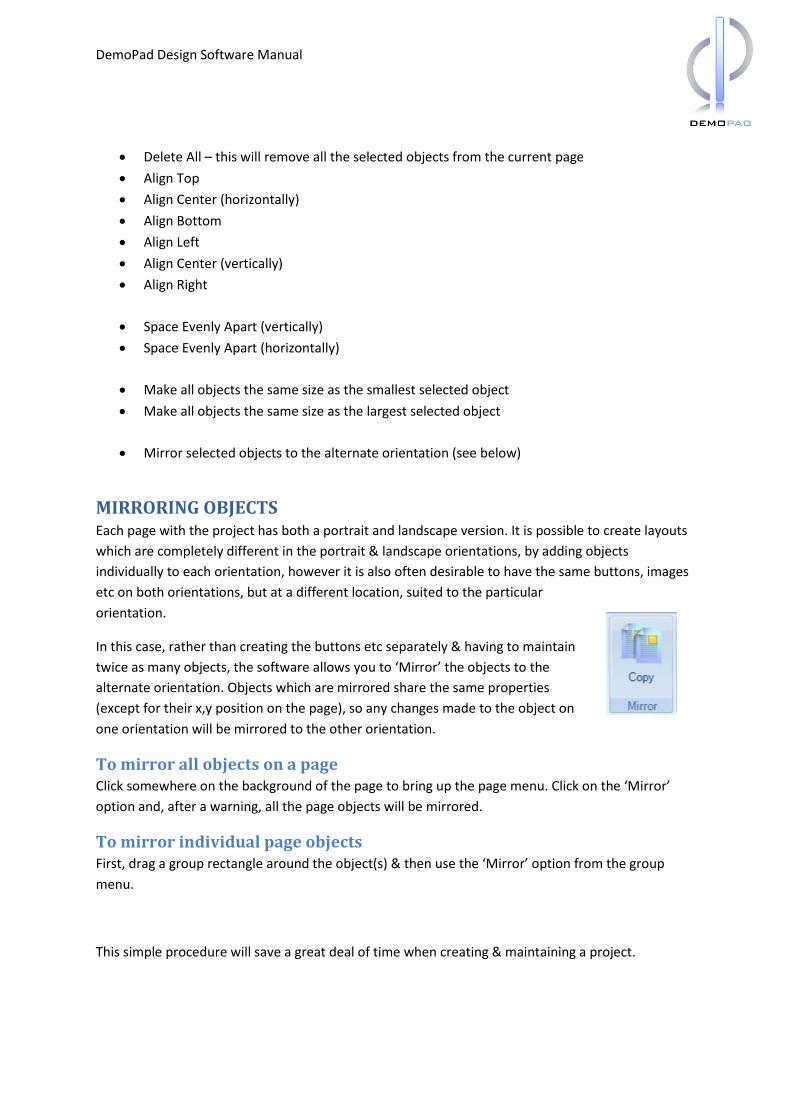
You will then see the group menu options, shown below.
You then have the following options to perform on all the objects:
DemoPad Design Software Manual
Delete All – this will remove all the selected objects from the current page
Align Top
Align Center (horizontally)
Align Bottom
Align Left
Align Center (vertically)
Align Right
Space Evenly Apart (vertically)
Space Evenly Apart (horizontally)
Make all objects the same size as the smallest selected object
Make all objects the same size as the largest selected object
Mirror selected objects to the alternate orientation (see below)
MIRRORING OBJECTS Each page with the project has both a portrait and landscape version. It is possible to create layouts
which are completely different in the portrait & landscape orientations, by adding objects
individually to each orientation, however it is also often desirable to have the same buttons, images
etc on both orientations, but at a different location, suited to the particular
orientation.
In this case, rather than creating the buttons etc separately & having to maintain
twice as many objects, the software allows you to ‘Mirror’ the objects to the
alternate orientation. Objects which are mirrored share the same properties
(except for their x,y position on the page), so any changes made to the object on
one orientation will be mirrored to the other orientation.
To mirror all objects on a page Click somewhere on the background of the page to bring up the page menu. Click on the ‘Mirror’
option and, after a warning, all the page objects will be mirrored.
To mirror individual page objects First, drag a group rectangle around the object(s) & then use the ‘Mirror’ option from the group
menu.
This simple procedure will save a great deal of time when creating & maintaining a project.
DemoPad Design Software Manual
Note: Objects which have already been mirrored will not be ‘copied’ again, nor will their location
information be lost, so you can choose to mirror all objects on a page after adding some objects
without fear of having to reset the location of objects which you have previously mirrored.
USING SUB PAGES A sub page is a page canvas area which is smaller than the project page canvas size. Sub pages can
be inserted as page objects onto normal pages, and can either be always visible, or appear in
response to a flag condition (as can any page object). Any sub page which appears will ‘block’ any
buttons which are placed behind the sub page area. Please refer to ‘Using Merged Pages’ which do
not block buttons.
Sub pages are typically used to show remote controls of devices, or temporary GUI menu options, or
where common commands are needed – sub pages prevent you having to continually copy/paste
onto each page.
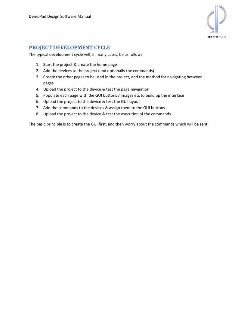
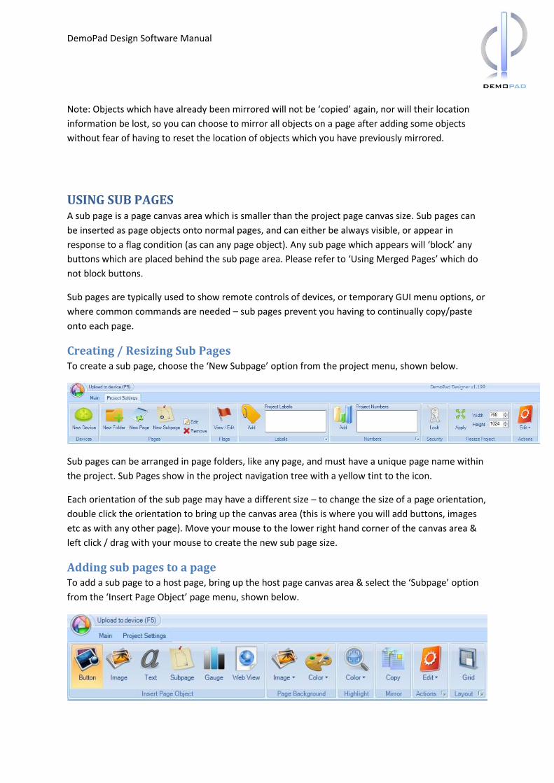
Creating / Resizing Sub Pages To create a sub page, choose the ‘New Subpage’ option from the project menu, shown below.
Sub pages can be arranged in page folders, like any page, and must have a unique page name within
the project. Sub Pages show in the project navigation tree with a yellow tint to the icon.
Each orientation of the sub page may have a different size – to change the size of a page orientation,
double click the orientation to bring up the canvas area (this is where you will add buttons, images
etc as with any other page). Move your mouse to the lower right hand corner of the canvas area &
left click / drag with your mouse to create the new sub page size.
Adding sub pages to a page To add a sub page to a host page, bring up the host page canvas area & select the ‘Subpage’ option
from the ‘Insert Page Object’ page menu, shown below.
DemoPad Design Software Manual
Choosing this option will bring up the project navigation tree, if it is not already visible. Hover your
mouse over a particular orientation of the sub page you wish to add to see a preview of the sub
page. Then, move your mouse over the preview & left click / drag the sub page onto the host page,
just as you would with a button / image.
Making sub pages appear / vanish Please refer to the ‘Displaying objects dynamically’ section which applies to all page objects.
USING MERGED PAGES (not recommended) It is possible to merge 2 or more pages together such that all objects from the merged page appear
on the main page in addition to the main page objects. It is possible to use buttons from both the
main page and the merged page. Merged pages have the same canvas area as main pages, and are
created in the same way as ‘normal’ pages.
Merged pages are typically used where it is not possible to use sub pages to perform a particular
task (for example subpages do not allow buttons ‘underneath’ to be pressed), and should only be
used in this instance, as they are less efficient and can lead to performance issues with large
projects.
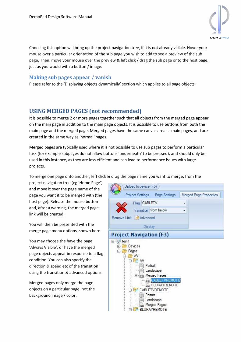
To merge one page onto another, left click & drag the page name you want to merge, from the
project navigation tree (eg ‘Home Page’)
and move it over the page name of the
page you want it to be merged with (the
host page). Release the mouse button
and, after a warning, the merged page
link will be created.
You will then be presented with the
merge page menu options, shown here.
You may choose the have the page
‘Always Visible’, or have the merged
page objects appear in response to a flag
condition. You can also specify the
direction & speed etc of the transition
using the transition & advanced options.
Merged pages only merge the page
objects on a particular page, not the
background image / color.
DemoPad Design Software Manual
DemoPad Design Software Manual
Sending Commands
This manual has so far dealt with the process of setting up the Graphical User Interface for your
project. This section deals with assigning commands to your buttons, so that they can affect external
equipment & actually ‘do’ something.
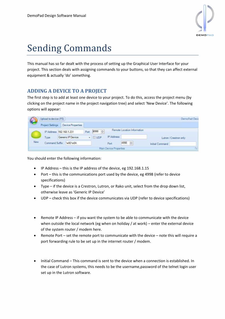
ADDING A DEVICE TO A PROJECT The first step is to add at least one device to your project. To do this, access the project menu (by
clicking on the project name in the project navigation tree) and select ‘New Device’. The following
options will appear:
You should enter the following information:
IP Address – this is the IP address of the device, eg 192.168.1.15
Port – this is the communications port used by the device, eg 4998 (refer to device
specifications)
Type – if the device is a Crestron, Lutron, or Rako unit, select from the drop down list,
otherwise leave as ‘Generic IP Device’
UDP – check this box if the device communicates via UDP (refer to device specifications)
Remote IP Address – if you want the system to be able to communicate with the device
when outside the local network (eg when on holiday / at work) – enter the external device
of the system router / modem here.
Remote Port – set the remote port to communicate with the device – note this will require a
port forwarding rule to be set up in the internet router / modem.
Initial Command – This command is sent to the device when a connection is established. In
the case of Lutron systems, this needs to be the username,password of the telnet login user
set up in the Lutron software.
DemoPad Design Software Manual
ENTERING OR IMPORTING COMMANDS Whilst it is possible to manually add each command to your project buttons, it is desirable to be able
to store these against the device, and call them up from the buttons. That way, any changes which
need to be made to the commands can be made once, and the entire project will be updated.
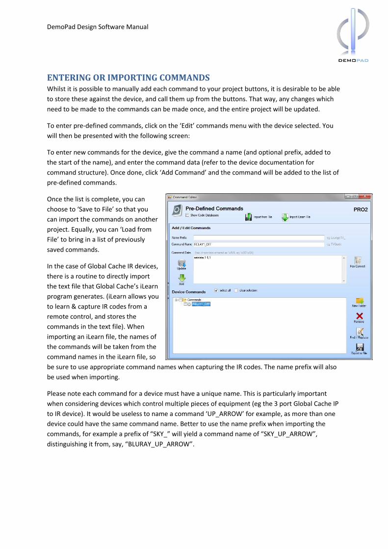
To enter pre-defined commands, click on the ‘Edit’ commands menu with the device selected. You
will then be presented with the following screen:
To enter new commands for the device, give the command a name (and optional prefix, added to
the start of the name), and enter the command data (refer to the device documentation for
command structure). Once done, click ‘Add Command’ and the command will be added to the list of
pre-defined commands.
Once the list is complete, you can
choose to ‘Save to File’ so that you
can import the commands on another
project. Equally, you can ‘Load from
File’ to bring in a list of previously
saved commands.
In the case of Global Cache IR devices,
there is a routine to directly import
the text file that Global Cache’s iLearn
program generates. (iLearn allows you
to learn & capture IR codes from a
remote control, and stores the
commands in the text file). When
importing an iLearn file, the names of
the commands will be taken from the
command names in the iLearn file, so
be sure to use appropriate command names when capturing the IR codes. The name prefix will also
be used when importing.
Please note each command for a device must have a unique name. This is particularly important
when considering devices which control multiple pieces of equipment (eg the 3 port Global Cache IP
to IR device). It would be useless to name a command ‘UP_ARROW’ for example, as more than one
device could have the same command name. Better to use the name prefix when importing the
commands, for example a prefix of “SKY_” will yield a command name of “SKY_UP_ARROW”,
distinguishing it from, say, “BLURAY_UP_ARROW”.
DemoPad Design Software Manual
SENDING HEX COMMANDS The command format entered in the pre-defined command screen, or when manually entering
commands is standard ASCII text. For those devices which require HEX bytes to be sent, you need
some way of entering the hex byte. For this, the software uses \x notation, for example to enter 3
hex bytes 0D 34 2A you would enter \x0D\x34\x2A in the software. Always use uppercase for the
hex numbers, and a lowercase x, eg \x0D is correct, \X0D or \x0d is not correct.
If you have a need to send \x as 2 ASCII characters, then use \\x
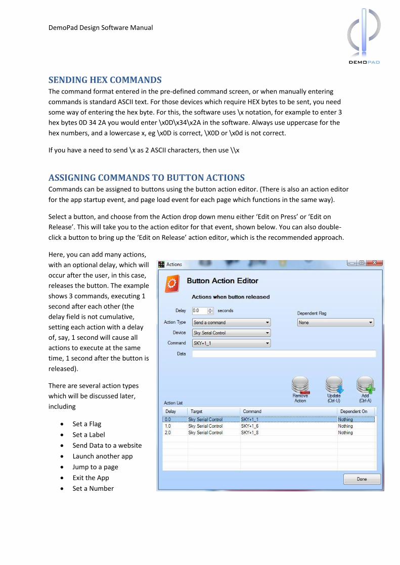
ASSIGNING COMMANDS TO BUTTON ACTIONS Commands can be assigned to buttons using the button action editor. (There is also an action editor
for the app startup event, and page load event for each page which functions in the same way).
Select a button, and choose from the Action drop down menu either ‘Edit on Press’ or ‘Edit on
Release’. This will take you to the action editor for that event, shown below. You can also double-
click a button to bring up the ‘Edit on Release’ action editor, which is the recommended approach.
Here, you can add many actions,
with an optional delay, which will
occur after the user, in this case,
releases the button. The example
shows 3 commands, executing 1
second after each other (the
delay field is not cumulative,
setting each action with a delay
of, say, 1 second will cause all
actions to execute at the same
time, 1 second after the button is
released).
There are several action types
which will be discussed later,
including
Set a Flag
Set a Label
Send Data to a website
Launch another app
Jump to a page
Exit the App
Set a Number
DemoPad Design Software Manual
For the ‘Send a command’ action type, you must select the device to send the command to, and
then either enter the command manually in the ‘Data’ text area, or if you have set some pre-defined
commands up, choose one from the drop down list. Note if you use a pre-defined command, and
that command is altered from the device pre-defined commands screen, the button will use the
updated command.
Once you have entered the required information, click ‘Add’, or press Control-A to add the action to
the list.
Editing / Removing Actions You can remove an action by clicking on the action line in the grid, & clicking ‘Remove Action’. You
can edit an action by clicking on the action in the list, making any necessary changes & then clicking
‘Update’ or pressing Control-U.
DemoPad Design Software Manual
Deploying & Running the Project
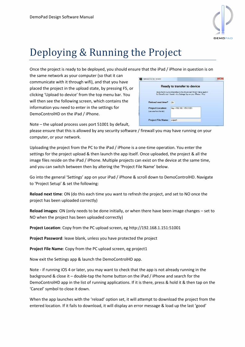
Once the project is ready to be deployed, you should ensure that the iPad / iPhone in question is on
the same network as your computer (so that it can
communicate with it through wifi), and that you have
placed the project in the upload state, by pressing F5, or
clicking ‘Upload to device’ from the top menu bar. You
will then see the following screen, which contains the
information you need to enter in the settings for
DemoControlHD on the iPad / iPhone.
Note – the upload process uses port 51001 by default,
please ensure that this is allowed by any security software / firewall you may have running on your
computer, or your network.
Uploading the project from the PC to the iPad / iPhone is a one-time operation. You enter the
settings for the project upload & then launch the app itself. Once uploaded, the project & all the
image files reside on the iPad / iPhone. Multiple projects can exist on the device at the same time,
and you can switch between then by altering the ‘Project File Name’ below.
Go into the general ‘Settings’ app on your iPad / iPhone & scroll down to DemoControlHD. Navigate
to ‘Project Setup’ & set the following:
Reload next time: ON (do this each time you want to refresh the project, and set to NO once the
project has been uploaded correctly)
Reload images: ON (only needs to be done initially, or when there have been image changes – set to
NO when the project has been uploaded correctly)
Project Location: Copy from the PC upload screen, eg http://192.168.1.151:51001
Project Password: leave blank, unless you have protected the project
Project File Name: Copy from the PC upload screen, eg project1
Now exit the Settings app & launch the DemoControlHD app.
Note - if running iOS 4 or later, you may want to check that the app is not already running in the
background & close it – double-tap the home button on the iPad / iPhone and search for the
DemoControlHD app in the list of running applications. If it is there, press & hold it & then tap on the
‘Cancel’ symbol to close it down.
When the app launches with the ‘reload’ option set, it will attempt to download the project from the
entered location. If it fails to download, it will display an error message & load up the last ‘good’
DemoPad Design Software Manual
project. Once the project has been downloaded & tested, set the ‘reload’ options to NO so that it
does not try to download the project each time the app is launched.
DEMOCONTROLHD SETTINGS In addition to the project setup options in the iPad / iPhone settings app, there are several other app
options, namely:
Remote Access – if set to ON, the project will use the ‘remote’ IP address & port settings
from the project file. This setting is used to access the app functions when away from the
local wireless network, but still connected to the internet.
Remember Last Page – if set to ON, the app will load up the last page it displayed when you
launch the app.
Multitasking – if supported on your device, setting this to ON will send the app to the
background tasks on the iPad / iPhone when you ‘exit’ the app. It is recommended only to
use this option when the size of your project images results in a slow launch time, which can
be avoided with the multitasking option.
Key Clicks – enables / disables a key click sound when buttons are pressed
Disable Pinch Zoom – gives the user the choice of being able to zoom in to the GUI using a
pinch gesture
Startup Message: which is displayed while the app starts up
ZOOMING IN ON THE APP GUI Whilst the majority of functionality is defined by your project file (buttons which link to other pages
etc), you can always use the 2-finger ‘pinch in’ gesture to zoom in to the GUI. When zoomed in, you
can use a single-finger drag operation to scroll around the page area. To zoom out, use the ‘pinch
out’ gesture.
These gestures must be performed on ‘empty’ areas of the screen where there are no pressable
buttons.
DemoPad Design Software Manual
Advanced Topics
USING FLAGS Flags are Boolean (YES/NO) variables within the software. They can have one of two values: ON, or
OFF. Any action can set the status of a flag, and they are used for the following purposes:
1. Flag Dependent Actions – where particular parts of an action list are only executed if a
particular flag is set to, say, ‘ON’. (Conditional Logic Statements)
2. Making objects / pages appear – you can have certain objects appear on screen in response
to a flag being set to ‘ON’, and have them disappear when the flag is set to ‘OFF’
3. Disabling buttons – you can disable a button by having all actions dependent on a flag
To create a flag, choose ‘Add’ from the ‘Project Flags’ option of the project menu. A flag simply has a
name, which must be unique. You can organise flags in group folders. When the DemoControlHD
app is first launched, all flags have a value of ‘OFF’. (Unless you have selected the ‘Remember Last
Page’ option in the app settings, in which case all flags have the value they were last set to when the
app was running)
A flag can be set by creating an action on a button push/release, page load, or app load event. Whilst
in the action editor, select ‘Set a Flag’ as the action type, choose the flag from the drop down list &
set the value (either ‘ON’ or ‘OFF’). You can also choose to set an entire flag group to ON or OFF.
It is often useful to use the “App Startup Actions” editor to set the default state of certain flags, so
that they are set to “ON” when the app is launched.
Flag Dependent Actions At the point at which actions are due to execute (ie after their delay, if any), the system can look at
the state of a flag to determine whether to actually process the action. To set this up, simply choose
a ‘Dependent Flag’ before adding the action, and choose the value that flag must be equal to in
order for the action to occur.
Making objects appear Merged pages, and page objects can have an optional ‘Display’ flag, which means that they only
appear if a flag is set to ‘ON’. This can be useful for bringing up device remote controls etc. Please
refer to the “Displaying objects dynamically” section for more information.
Disabling buttons Whilst dependent actions are only executed if the state of a flag matches the required state, the
decision whether or not to execute the action is made at the time the action is supposed to execute.
DemoPad Design Software Manual
It is also possible to completely disable all actions from occurring, based on a global button
dependent flag. This is configured by expanding the ‘Actions’ menu for the button. If a dependent
flag is selected, and the condition is not met at the point that the button is pressed / released, then
no associated actions will occur – whether they themselves are dependent on a flag or not –
effectively you are disabling the button, based on the condition of a flag.
USING LABELS Labels are text variables within the software. They are set up in the same way as flags, ie they have a
name, but they also have a ‘Default Value’. This is the value of the label when the DemoControlHD
app is launched.
A label can be set by creating an action on a button push/release, page load, or app load event.
Whilst in the action editor, select ‘Set a Label’ as the action type, choose the label name from the
drop down list & set the value (any text value, eg “TV IS SWITHCED ON”)
Buttons & text objects can have these dynamic labels associated with them, and the text which
appears on the object will reflect the value of the label. This is particularly useful when using Toggle
buttons, where the text on the button can change depending on the button function.
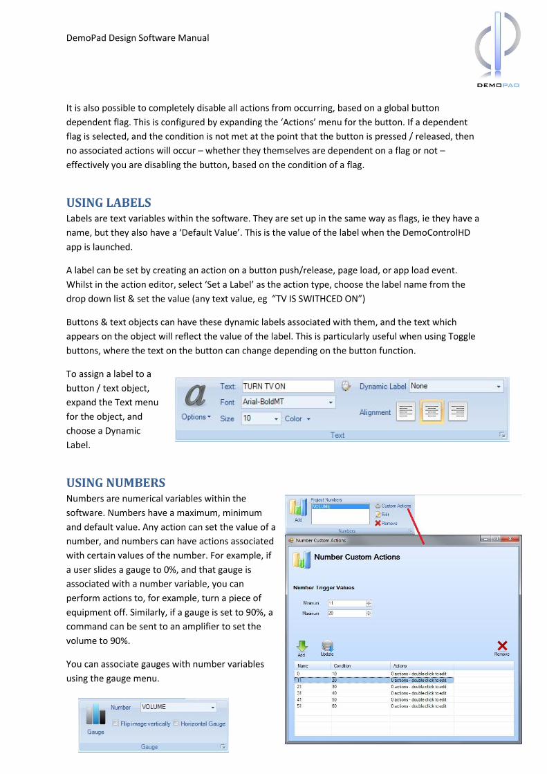
To assign a label to a
button / text object,
expand the Text menu
for the object, and
choose a Dynamic
Label.
USING NUMBERS Numbers are numerical variables within the
software. Numbers have a maximum, minimum
and default value. Any action can set the value of a
number, and numbers can have actions associated
with certain values of the number. For example, if
a user slides a gauge to 0%, and that gauge is
associated with a number variable, you can
perform actions to, for example, turn a piece of
equipment off. Similarly, if a gauge is set to 90%, a
command can be sent to an amplifier to set the
volume to 90%.
You can associate gauges with number variables
using the gauge menu.
DemoPad Design Software Manual
DYNAMICALLY LOADING IMAGES FROM THE WEB / IP CAMERAS It is possible for the app to retrieve an image directly from an IP address or host name, and display it
on the user interface. Labels are used to ‘point’ to the image location, and if, in the case of many IP
cameras, this image is refreshed, you can continually refresh the image on the iPad / iPhone as well.
To set this up, create a label (eg called CAMERAFEED), and set the default value of the image
location. This might be something like: “http://192.168.1.54/Jpeg/CamImg.jpg”. Then, add an image
object to a page – you can choose any image initially, however the transparent50x50.png image
which is supplied with the software is ideal for this. Resize the image on screen to match either the
size of the target image, or to whichever size you choose (dynamically loaded images are stretched
to fit the object they are displayed in).
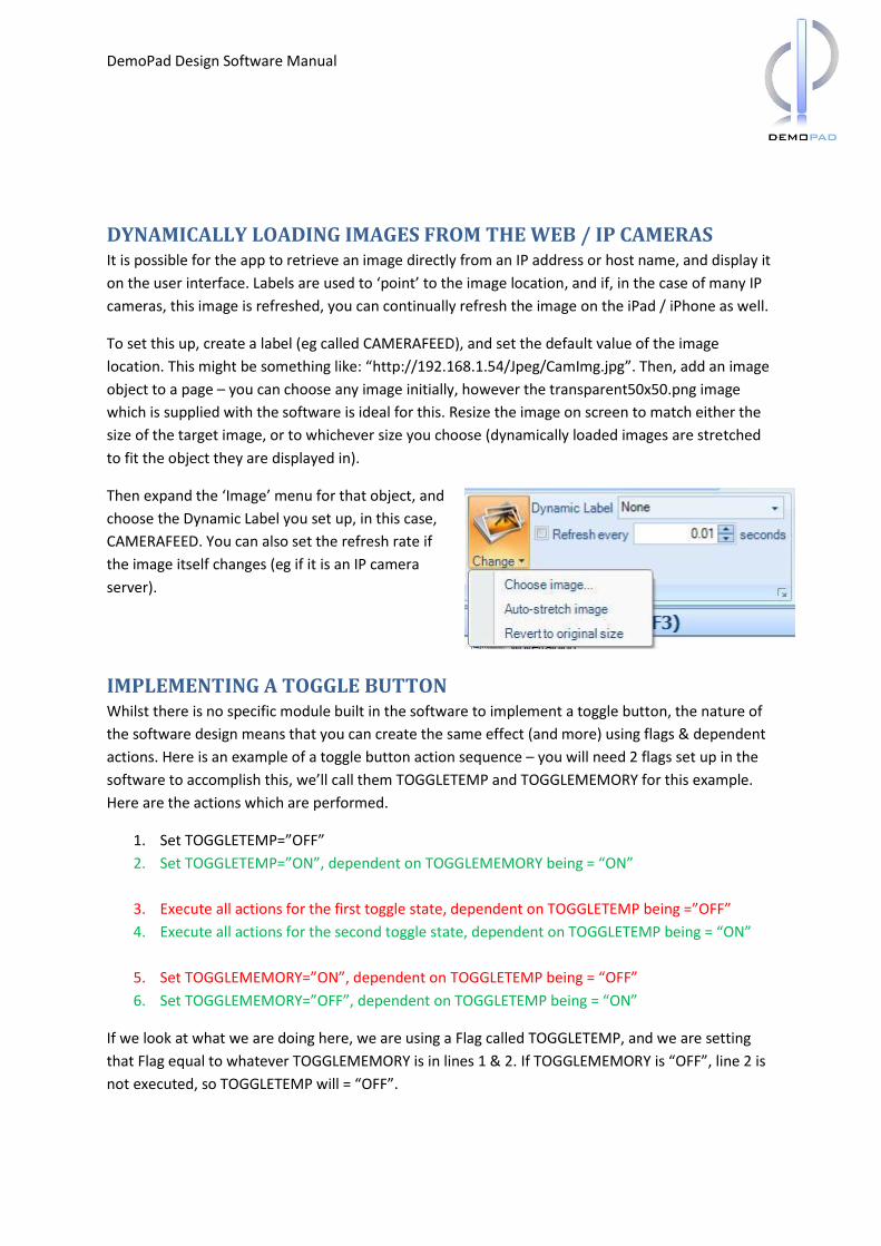
Then expand the ‘Image’ menu for that object, and
choose the Dynamic Label you set up, in this case,
CAMERAFEED. You can also set the refresh rate if
the image itself changes (eg if it is an IP camera
server).
IMPLEMENTING A TOGGLE BUTTON Whilst there is no specific module built in the software to implement a toggle button, the nature of
the software design means that you can create the same effect (and more) using flags & dependent
actions. Here is an example of a toggle button action sequence – you will need 2 flags set up in the
software to accomplish this, we’ll call them TOGGLETEMP and TOGGLEMEMORY for this example.
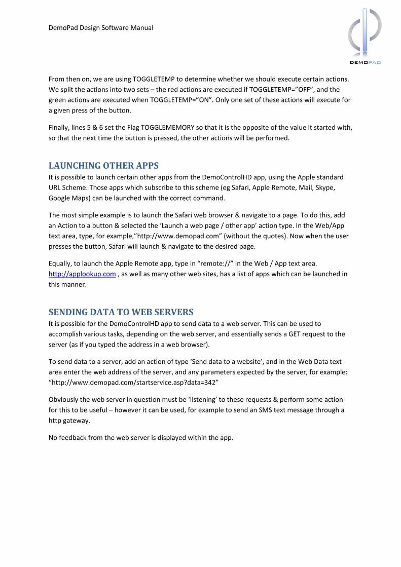
Here are the actions which are performed.
1. Set TOGGLETEMP=”OFF”
2. Set TOGGLETEMP=”ON”, dependent on TOGGLEMEMORY being = “ON”
3. Execute all actions for the first toggle state, dependent on TOGGLETEMP being =”OFF”
4. Execute all actions for the second toggle state, dependent on TOGGLETEMP being = “ON”
5. Set TOGGLEMEMORY=”ON”, dependent on TOGGLETEMP being = “OFF”
6. Set TOGGLEMEMORY=”OFF”, dependent on TOGGLETEMP being = “ON”
If we look at what we are doing here, we are using a Flag called TOGGLETEMP, and we are setting
that Flag equal to whatever TOGGLEMEMORY is in lines 1 & 2. If TOGGLEMEMORY is “OFF”, line 2 is
not executed, so TOGGLETEMP will = “OFF”.
DemoPad Design Software Manual
From then on, we are using TOGGLETEMP to determine whether we should execute certain actions.
We split the actions into two sets – the red actions are executed if TOGGLETEMP=”OFF”, and the
green actions are executed when TOGGLETEMP=”ON”. Only one set of these actions will execute for
a given press of the button.
Finally, lines 5 & 6 set the Flag TOGGLEMEMORY so that it is the opposite of the value it started with,
so that the next time the button is pressed, the other actions will be performed.
LAUNCHING OTHER APPS It is possible to launch certain other apps from the DemoControlHD app, using the Apple standard
URL Scheme. Those apps which subscribe to this scheme (eg Safari, Apple Remote, Mail, Skype,
Google Maps) can be launched with the correct command.
The most simple example is to launch the Safari web browser & navigate to a page. To do this, add
an Action to a button & selected the ‘Launch a web page / other app’ action type. In the Web/App
text area, type, for example,”http://www.demopad.com” (without the quotes). Now when the user
presses the button, Safari will launch & navigate to the desired page.
Equally, to launch the Apple Remote app, type in “remote://” in the Web / App text area.
http://applookup.com , as well as many other web sites, has a list of apps which can be launched in
this manner.
SENDING DATA TO WEB SERVERS It is possible for the DemoControlHD app to send data to a web server. This can be used to
accomplish various tasks, depending on the web server, and essentially sends a GET request to the
server (as if you typed the address in a web browser).
To send data to a server, add an action of type ‘Send data to a website’, and in the Web Data text
area enter the web address of the server, and any parameters expected by the server, for example: