Mitsubishi Heavy Industries Technical Review Vol. 52 No. 4 (December 2015) 47 *1 Chief Staff Manager, Fuel Cell Business Department, Mitsubishi Hitachi Power Systems, Ltd. *2 Fuel Cell Business Department, Mitsubishi Hitachi Power Systems, Ltd. *3 Heat Transfer Research Department, Research & Innovation Center, Technology & Innovation Headquarters *4 System Engineering Department, UNION Design Office, Ltd. Demonstration of SOFC-Micro Gas Turbine (MGT) Hybrid Systems for Commercialization YOSHIMASA ANDO *1 HIROYUKI OOZAWA *1 MASAHIRO MIHARA *2 HIROKI IRIE *2 YASUTAKA URASHITA *3 TAKUO IKEGAMI *4 To develop a commercial model of a Solid Oxide Fuel Cell (SOFC)-Micro Gas Turbine (MGT) hybrid system, Mitsubishi Hitachi Power Systems, Ltd. (MHPS) delivered the demonstration unit prototype to Kyushu University, which is now undergoing demonstration operation. This demonstration unit was delivered to the "Verification of a Smart Fuel Cell Society" in the Green Asia International Strategic Comprehensive Special Zone at Kyushu University. The demonstration is being conducted as a collaborative research project by Kyushu University and Mitsubishi Hitachi Power Systems (MHPS). This report describes the outline of the hybrid demonstration unit, its operational achievements and future plans. | 1. Introduction To strike a balance between CO 2 reduction to mitigate global warming and the electricity security essential for modern society, we have to promote an energy mix reasonable in terms of both quality and quantity by integrating high-efficiency distributed power sources and new energy technologies (renewable energy, etc.) with advanced power grids composed of centralized power systems (thermal power plants, etc.). For global energy resource conservation, it is an essential and urgent issue to thoroughly and effectively use fossil fuel as much as possible through the development and early adoption of high-efficiency power generation systems. MHPS has focused on developing a high-efficiency SOFC hybrid power generation system with very wide power output ranges. The system covers everything from medium-capacity distributed power sources (several hundred kW) to large-capacity centralized power sources including Gas Turbine Fuel Cell (GTFC) combined cycle and Integrated coal Gasification Fuel Cell (IGFC) combined cycle technologies, which are defined by the "Council for promoting the early realization of next generation thermal power generation" of the Ministry of Economy, Trade and Industry (METI). MHPS is eyeing the full commercialization of a hybrid system, as a moderate-sized distributed power source, combining a SOFC system and a micro gas turbine (MGT) in fiscal 2017 or later. The demonstration unit was delivered to Kyushu University. | 2. Verification of a Smart Fuel Cell Society at Kyushu University The "Next-Generation Fuel Cell Research Center (NEXT-FC)" was established on the Ito Campus of Kyushu University (Nishi-ku, Fukuoka) aiming to fully disseminate SOFC by promoting industry-academia cooperation. The Center has conducted demonstration research under the "Verification of a Smart Fuel Cell Society" in the Green Asia International Strategic Comprehensive Special Zone, as well as fundamental research for enhancing the related SOFC's performance, durability and reliability. The demonstration project advertised for several kW-scale commercial fuel cell systems and several hundred kW-scale commercial and industrial fuel cell systems in fiscal 2014. MHPS
*1 Chief Staff Manager, Fuel Cell Business Department, Mitsubishi Hitachi Power Systems, Ltd. *2 Fuel Cell Business Department, Mitsubishi Hitachi Power Systems, Ltd. *3 Heat Transfer Research Department, Research & Innovation Center, Technology & Innovation Headquarters *4 System Engineering Department, UNION Design Office, Ltd.
Demonstration of SOFC-Micro Gas Turbine (MGT) Hybrid Systems for Commercialization
YOSHIMASA ANDO*1 HIROYUKI OOZAWA*1
MASAHIRO MIHARA*2 HIROKI IRIE*2
YASUTAKA URASHITA*3 TAKUO IKEGAMI*4
To develop a commercial model of a Solid Oxide Fuel Cell (SOFC)-Micro Gas Turbine
(MGT) hybrid system, Mitsubishi Hitachi Power Systems, Ltd. (MHPS) delivered the demonstrationunit prototype to Kyushu University, which is now undergoing demonstration operation. This demonstration unit was delivered to the "Verification of a Smart Fuel Cell Society" in the Green Asia International Strategic Comprehensive Special Zone at Kyushu University. The demonstrationis being conducted as a collaborative research project by Kyushu University and Mitsubishi Hitachi Power Systems (MHPS). This report describes the outline of the hybrid demonstration unit,its operational achievements and future plans.
|1. Introduction To strike a balance between CO2 reduction to mitigate global warming and the electricity
security essential for modern society, we have to promote an energy mix reasonable in terms ofboth quality and quantity by integrating high-efficiency distributed power sources and new energy technologies (renewable energy, etc.) with advanced power grids composed of centralized powersystems (thermal power plants, etc.). For global energy resource conservation, it is an essential andurgent issue to thoroughly and effectively use fossil fuel as much as possible through the development and early adoption of high-efficiency power generation systems.
MHPS has focused on developing a high-efficiency SOFC hybrid power generation system with very wide power output ranges. The system covers everything from medium-capacity distributed power sources (several hundred kW) to large-capacity centralized power sources including Gas Turbine Fuel Cell (GTFC) combined cycle and Integrated coal Gasification Fuel Cell(IGFC) combined cycle technologies, which are defined by the "Council for promoting the early realization of next generation thermal power generation" of the Ministry of Economy, Trade andIndustry (METI). MHPS is eyeing the full commercialization of a hybrid system, as a moderate-sized distributed power source, combining a SOFC system and a micro gas turbine (MGT) in fiscal 2017 or later. The demonstration unit was delivered to Kyushu University.
|2. Verification of a Smart Fuel Cell Society at Kyushu University The "Next-Generation Fuel Cell Research Center (NEXT-FC)" was established on the Ito
Campus of Kyushu University (Nishi-ku, Fukuoka) aiming to fully disseminate SOFC by promoting industry-academia cooperation. The Center has conducted demonstration research underthe "Verification of a Smart Fuel Cell Society" in the Green Asia International Strategic Comprehensive Special Zone, as well as fundamental research for enhancing the related SOFC'sperformance, durability and reliability.
The demonstration project advertised for several kW-scale commercial fuel cell systems and several hundred kW-scale commercial and industrial fuel cell systems in fiscal 2014. MHPS
submitted the hybrid system, which was selected and ordered as a commercial and industrialsystem.
In addition to the fuel cell system, the Ito Campus showcases and demonstrates many hydrogen energy systems, and many people visit.
|3. Development of SOFC-MGT hybrid system Prior to the demonstration unit, the successor tubular type SOFC gas turbine hybrid system
achieved a continuous power generation period of 4,100 hours, a cumulative operation period of 5,067 hours, and a voltage drop rate of 0%/1,000 hours under the NEDO (New Energy andIndustrial Technology Development Organization) "Operational demonstration of tubular SOFCgas turbine hybrid system for commercialization" project, which ended in September 2014. Theoperation was well-controlled automatically during the boot and load elevation, and safe and secureshutdown was also verified in emergency shutdown testing assuming accidents.
As a distributed power source for marketing, MHPS has studied a more compact cell stackwith a high output density (Model 10 → Model 15) based on the achievement described above, pursuing system downsizing to meet market needs. The outline of the Model 15cell stack is described as follows. 3.1 Structure of tubular type SOFC
Figure 1 shows the structure of the power generation element of MHPS's tubular SOFCstack. On the outer surface of the substrate tube, which is a high-strength ceramic structural member, a cell (anode, electrolyte, and cathode) reacting to generate power is formed. Anelectron-conductive ceramic interconnector connects the cells in series. This structure makes itpossible to efficiently gain low current output at high voltage. Each cartridge consists of bundled cell stacks, supporting members, feed and vents for fuel and air, as well as a current outlet. Thisstructure makes it possible to produce several tens of kW of electrical output. Each module has apressure vessel that contains the several cartridges needed to obtain required capacity. This hierarchical structure makes it easier to install and maintain the system (Figure 2). The SOFC hybrid demonstration system was realized by combining the SOFC pressurized module and anMGT.
3.2 Development of Model 15 cell stack, cartridge and system As shown in MHI Technical Review Vol. 52 No. 2, MHPS has developed proprietary
high-efficiency cell stacks. The Model 15 cell stack has an enhanced interface between the electrode and electrolyte, achieving higher output density per unit volume and 50% higher outputdensity than the Model 10 (Figure 3). Making a cartridge with a higher density is one of MHPS's research targets. The tighter the cell stack is packed, the higher the heat density. Accordingly, byapplying heat transfer and cooling designs to the cartridge, the heat transfer property was controlledto maintain the conventional amount of heat transfer at the power generation component and itsfront and back portions. By decreasing the radius and increasing the length of the cell stack, theoutput density per unit volume is increased.
Figure 3 Tubular SOFC cell stack
As an advance demonstration of the Model 15 cartridge mounted on the demonstration unit,one of the cartridges was installed to test the performance at the Senju Techno Station of TokyoGas Co., Ltd. In addition to a long-term durability test, a parameter test with changing gasconditions and an emergency shutdown test were conducted. The cartridge continuously generatedelectricity stably for more than 1,000 hours (Figure 4).
Figure 4 Cartridge demonstration of Model 15
As described above, the installation area for the Model 15 cell stack is more than 40%smaller as a result of reducing the cell stack radius and increasing its length and packing density (Figure 5).
Figure 5 Development of cell stack, cartridge and module of Model 15
|4. Main specifications, system configuration, and electric powersystem
4.1 Main specifications and features The SOFC-MGT hybrid system delivered to Kyushu University is the first demonstration
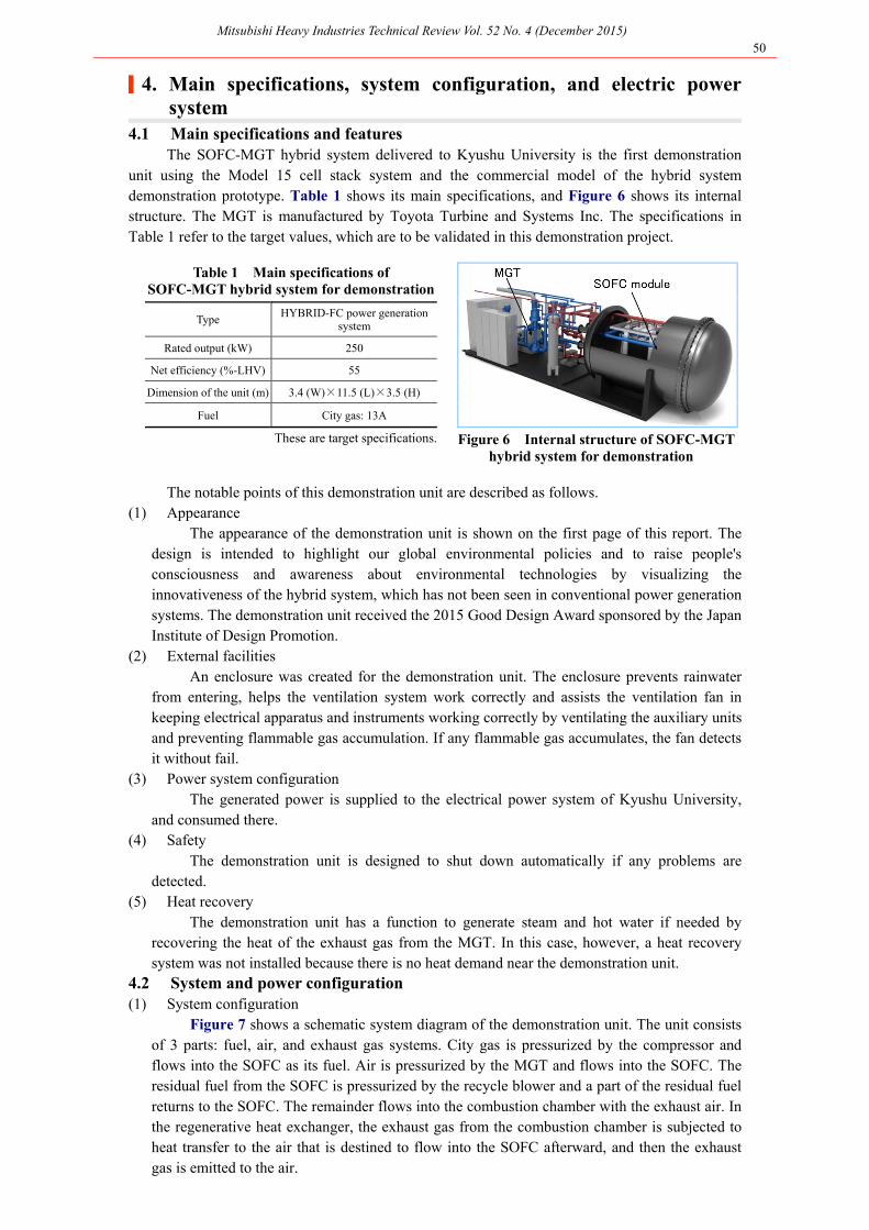
unit using the Model 15 cell stack system and the commercial model of the hybrid systemdemonstration prototype. Table 1 shows its main specifications, and Figure 6 shows its internal structure. The MGT is manufactured by Toyota Turbine and Systems Inc. The specifications inTable 1 refer to the target values, which are to be validated in this demonstration project.
Table 1 Main specifications of SOFC-MGT hybrid system for demonstration
Type HYBRID-FC power generation system
Rated output (kW) 250
Net efficiency (%-LHV) 55
Dimension of the unit (m) 3.4 (W)×11.5 (L)×3.5 (H)
Fuel City gas: 13A
These are target specifications. Figure 6 Internal structure of SOFC-MGT hybrid system for demonstration
The notable points of this demonstration unit are described as follows. (1) Appearance
The appearance of the demonstration unit is shown on the first page of this report. The design is intended to highlight our global environmental policies and to raise people'sconsciousness and awareness about environmental technologies by visualizing theinnovativeness of the hybrid system, which has not been seen in conventional power generation systems. The demonstration unit received the 2015 Good Design Award sponsored by the JapanInstitute of Design Promotion.
(2) External facilities An enclosure was created for the demonstration unit. The enclosure prevents rainwater
from entering, helps the ventilation system work correctly and assists the ventilation fan inkeeping electrical apparatus and instruments working correctly by ventilating the auxiliary unitsand preventing flammable gas accumulation. If any flammable gas accumulates, the fan detectsit without fail.
(3) Power system configuration The generated power is supplied to the electrical power system of Kyushu University,
and consumed there. (4) Safety
The demonstration unit is designed to shut down automatically if any problems are detected.
(5) Heat recovery The demonstration unit has a function to generate steam and hot water if needed by
recovering the heat of the exhaust gas from the MGT. In this case, however, a heat recoverysystem was not installed because there is no heat demand near the demonstration unit.
4.2 System and power configuration (1) System configuration
Figure 7 shows a schematic system diagram of the demonstration unit. The unit consistsof 3 parts: fuel, air, and exhaust gas systems. City gas is pressurized by the compressor andflows into the SOFC as its fuel. Air is pressurized by the MGT and flows into the SOFC. Theresidual fuel from the SOFC is pressurized by the recycle blower and a part of the residual fuelreturns to the SOFC. The remainder flows into the combustion chamber with the exhaust air. Inthe regenerative heat exchanger, the exhaust gas from the combustion chamber is subjected toheat transfer to the air that is destined to flow into the SOFC afterward, and then the exhaust gas is emitted to the air.
Figure 7 Schematic system diagram of SOFC-MGT hybrid system for demonstration
(2) Electric power system
Figure 8 shows the electric power system of the demonstration unit. The DC output from the SOFC is converted to AC (210 V, 3-phase). The converted output is then intermixed with AC (210 V, 3-phase) from the MGT and the voltage is transformed to AC (6,600 V, 3-phase) by the transformer to flow into the electric power system. A part of the AC output (210 V, 3-phase) from the SOFC and MGT also flows into their auxiliary equipment. At start-up, the demonstration unit receives power from the power grid to boost the auxiliary equipment.
Figure 8 Schematic electric power system diagram of SOFC-MGT hybrid system for demonstration
|5. Operational achievements As scheduled, the demonstration unit was delivered to Kyushu University in March 2015. It
completed trial operations, underwent several adjustments, and started the demonstration operationfor testing its power generation performance. In this demonstration, several tests were conductedincluding load increase, reboot after shutdown and hot reboot. The data was collected for the purpose of realizing fully-automated operation. In September 2015, the demonstration unit
underwent a scheduled shut down due to the inspection of the electrical equipment of the campus.By that point of time, the demonstration unit had achieved 2,800 hours of cumulative operation.
In this case, the demonstration unit, which was connected to the electrical power system onthe Kyushu University campus and installed at an outdoor location, was directly exposed tooutdoor climate conditions such as air temperature differences, typhoons and lightning strikes. Thedemonstration unit experienced an emergency shutdown due to instantaneous blackouts fromlightning strikes. It precisely detected the abnormal conditions and shut down its operation safely and properly. There was no damage to the SOFC, and the demonstration unit rebooted its operationthe same day.
This demonstration unit generated 200 kW and reached a generation efficiency of over 54%(AC, LHV, 15°C inlet temperature-equivalent). No performance degradation was observed (voltagedegradation at the same current levels). The NOx concentration in the exhaust gas was under theminimum limit of detection (<5 ppm) under stable operation, showing its high environmentalperformance.
It took about 2.5 hours for the SOFC to reach full-load operation from no-load under hot conditions, and took about 1 hour to go from full-load to no-load. We plan further testing to validate even shorter times.
|6. Future plans After a regular inspection, the demonstration unit rebooted on the last day of September 2015
and the demonstration operation resumed. Several tests are planned such as a load variation test where the load is to be increased from a cold start-up and a long-term durability test until the end of fiscal 2016.
These tests will be conducted as part of the collaborative research of Kyushu University andMHPS to detect and evaluate challenges for adoption and points to be improved.
|7. Conclusion MHPS plans to market the SOFC-MGT hybrid system as an energy device that helps reduce
CO2 emissions, facilitates energy resource conservation, and introduces renewable energy ineconomical and rational ways.
METI compiled a Strategic Road Map for Hydrogen and Fuel Cells in June 2014, citing the commercialization of fuel cells for commercial and industrial use in fiscal 2017.
With this prototype demonstration unit of the SOFC hybrid system delivered to KyushuUniversity, we aim to firmly establish the SOFC-MGT hybrid technology, promote its early commercialization and realize a "safe and sustainable environmentally-conscious society" based on the promotion of distributed power sources.
Finally, we would like to thank all of our partners for their support and advice about thedevelopment and the delivery of the demonstration unit to Kyushu University. We are lookingforward to their continued support.
Reference 1. Kobayashi, Y. et al., Development of Next-Generation Large-Scale SOFC toward Realization of a