Demonstration Plant for Distributed Production of Hydrogen from Steam Reforming of Methane Seris E.L.C. 1 , Abramowitz G. 1 , Johnston A.M. 2 , Haynes B.S. 1 1 Dept. of Chemical Engineering, University of Sydney, Sydney, Australia 2006. 2 Heatric (a division of Meggitt (UK) Ltd), Sydney, Australia. ABSTRACT We describe and demonstrate a technique for the creation of highly intensified, highly integrated chemical plant. The process is implemented using Printed Circuit Heat Exchanger (PCHE) technology in which the fluid passages and vessels are etched into flat plates, with the plates being stacked and bonded to create highly integrated modules. The manufacturing technique allows extraordinary complexity in the routing of fluid streams through the process, thus enabling very high levels of process integration to be achieved without significant capital or plant volume penalty. The fine passages employed in the structure have characteristic dimensions of around 1 mm, thus promoting further process intensification especially in heat transfer. The PCHE technique produces scaleable modules ideally suited to a wide range of production capacities, from miniplant to world scale. In our work, we explore the concept of distributed manufacture based on miniplants, as espoused by Benson and Ponton more than 10 years ago. We believe this paradigm offers new capital-accessible opportunities for chemical processing in smaller and more isolated economies such as in Australia and in the developing countries. A pilot plant for the production of syngas or hydrogen by the reforming of natural gas with steam has been installed at the University of Sydney. The main plant module contains 9 reactors, 10 combustors and 11 heat exchangers in a single integrated block. We describe the system in detail and the experimental set up for the operation and control of the system. 1. NOVEL MANUFACTURING CONCEPT: DISTRIBUTED PRODUCTION Chemical plants are large, and getting larger, because economies of scale reduce the capital component of the unit costs of production; they are centralised because they can share site zoning and utilities such as power, steam, and cooling water. These factors have led to an inexorable growth in the size and concentration of chemical plant, with globalisation and international trade working to penalise sub-“world scale” production. Isolated economies such as Australia and many developing countries increasingly fail to be able to provide the capital or the market to be able to sustain world-scale production. This paper describes a pilot plant facility at the University of Sydney that we believe sets a benchmark for demonstration of a new paradigm for chemical manufacture, namely distributed production in small, local facilities. While our ultimate vision is to overturn the “tyranny of scale”, the facility also serves to demonstrate a process with very high levels of heat integration for the efficient production of syngas through steam-methane reforming. The potential advantages of distributed chemicals manufacture in smaller on-site, or regional facilities have long been recognised (Benson and Ponton, 1993). Not only could such a plant be cheaper to build (as the economy of scale is shifted from the chemical product to the production of the plants themselves), it would offer improved safety (both in the process and in the bulk storage and transport of chemical products), and better reliability and continuity of
Transcript
Demonstration Plant for Distributed Production of Hydrogen from Steam Reforming of Methane
Seris E.L.C.1, Abramowitz G.1, Johnston A.M.2, Haynes B.S.11 Dept. of Chemical Engineering, University of Sydney, Sydney, Australia 2006. 2 Heatric (a division of Meggitt (UK) Ltd), Sydney, Australia.
ABSTRACT We describe and demonstrate a technique for the creation of highly intensified, highly integrated chemical plant. The process is implemented using Printed Circuit Heat Exchanger (PCHE) technology in which the fluid passages and vessels are etched into flat plates, with the plates being stacked and bonded to create highly integrated modules. The manufacturing technique allows extraordinary complexity in the routing of fluid streams through the process, thus enabling very high levels of process integration to be achieved without significant capital or plant volume penalty. The fine passages employed in the structure have characteristic dimensions of around 1 mm, thus promoting further process intensification especially in heat transfer.
The PCHE technique produces scaleable modules ideally suited to a wide range of production capacities, from miniplant to world scale. In our work, we explore the concept of distributed manufacture based on miniplants, as espoused by Benson and Ponton more than 10 years ago. We believe this paradigm offers new capital-accessible opportunities for chemical processing in smaller and more isolated economies such as in Australia and in the developing countries.
A pilot plant for the production of syngas or hydrogen by the reforming of natural gas with steam has been installed at the University of Sydney. The main plant module contains 9 reactors, 10 combustors and 11 heat exchangers in a single integrated block. We describe the system in detail and the experimental set up for the operation and control of the system.
1. NOVEL MANUFACTURING CONCEPT: DISTRIBUTED PRODUCTION Chemical plants are large, and getting larger, because economies of scale reduce the capital component of the unit costs of production; they are centralised because they can share site zoning and utilities such as power, steam, and cooling water. These factors have led to an inexorable growth in the size and concentration of chemical plant, with globalisation and international trade working to penalise sub-“world scale” production. Isolated economies such as Australia and many developing countries increasingly fail to be able to provide the capital or the market to be able to sustain world-scale production.
This paper describes a pilot plant facility at the University of Sydney that we believe sets a benchmark for demonstration of a new paradigm for chemical manufacture, namely distributed production in small, local facilities. While our ultimate vision is to overturn the “tyranny of scale”, the facility also serves to demonstrate a process with very high levels of heat integration for the efficient production of syngas through steam-methane reforming.
The potential advantages of distributed chemicals manufacture in smaller on-site, or regional facilities have long been recognised (Benson and Ponton, 1993). Not only could such a plant be cheaper to build (as the economy of scale is shifted from the chemical product to the production of the plants themselves), it would offer improved safety (both in the process and in the bulk storage and transport of chemical products), and better reliability and continuity of
supply. Today we can add the reduced risk of terrorist assault on major hazardous facilities as a further driver for distributed manufacture.
2. PROCESS INTENSIFICATION: THE ROUTE TO DISTRIBUTED SYSTEMS
Benson and Ponton (Benson and Ponton, 1993) observed that economic plant miniaturisation requires two key advances:
• Advanced manufacturing techniques are needed to produce the basic plant modules in large numbers. Different scales of operation can then be achieved by simply increasing the number of systems rather than through custom designs for each application - in the limit, one could go from bench-scale to industrial scale in a single step. Scaling by “numbering up” the systems further allows capital investment and market growth to be coupled, thus further reducing the financial risk of building large new facilities.
• Miniplants cannot be developed simply by implementing existing processes on a minute scale: new process designs are needed. In keeping with increasing demands for energy efficiency and environmental performance, these new designs must especially show significant improvements in these areas, relative to existing practice.
In recent years there has been a growing interest in developing microsytem technology (employing characteristic length scales in the range ~10 to ~1000 µm) for chemical processing. The main focus has been on repetitive synthetic and analytical chemistry, but the development of microreactors for bulk chemical manufacturing systems is also attracting interest, with topical developments in the field being described in the International Microreactor Technology (IMRET) conferences and in recent monographs (Ehrfeld et al., 2000; Hessel et al. 2004; 2005). While many examples of highly miniaturised components have been described in these publications, there are very few demonstrations of integrated micro-process plants of practical significance.
Heatric has specialised in process intensification since its inception in Australia in 1985 (Johnston, 1986). It is now the world-leading manufacturer of highly compact, industrial-scale heat exchangers (called Printed Circuit Heat Exchangers, PCHEs) for extreme processing conditions, including highly corrosive fluids at high temperatures, and high pressures. PCHEs are single-material (usually metal) matrices formed by diffusion bonding together plates into which fluid flow passages have been formed by photo-chemical machining. Complex fluid circuitry is readily implemented with this technique, with characteristic passage dimensions in the range 100 to 2000 µm as dictated by the cleanliness of the fluids and allowable pressure drops.
The pilot plant presented here employs the “Printed Circuit” manufacturing technology to create the essential fluidic structures of the process.
3. STEAM METHANE REFORMING MICROPLANT
3.1. Process Overview For the present application, the plant was scaled to produce hydrogen to fuel a notional 15kWe PEM fuel cell. The syngas produced in the steam reforming process could equally well be tailored for further processing, for example, to produce methanol, ammonia, or Fisher-Tropsch liquids. Indeed, we are currently developing such processes integrated with syngas production.
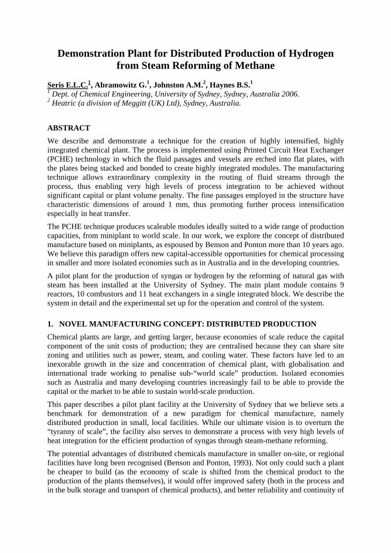
The plant is composed of 4 main modules: • pre-reforming module including the high temperature shift reactor. • reforming and combustion module. • low temperature shift reactor • steam drum
The only heat input to the process is provided by the catalytic combustion reactions in the reforming and combustion module. A highly complex network of Printed Circuit Heat Exchangers (PCHEs) distributes the heat to the other parts of the process (pre-reformer module, steam generation, pre-heat of the reactants). This is described in more detail in section 3.4.1. CO is oxidised to CO2 in the high and low temperature water gas shift reactors. Selective oxidation is not considered here because of its low impact on the heat integration, but this would be needed for implementation as a fuel processor for a PEM cell.
Figure 1: Process Overview
3.2. Steam Reformer Microplant Design basis The design basis of the steam reforming pilot plant, designed for a Proton Exchange Membrane Fuel Cell (PEMFC), is taken to be:
• 2 bara process side pressure, atmospheric combustion side pressure • Low-CO hydrogen required • Stand-alone system - no scope for export or import of steam. (The heat rejection
temperature from a fuel cell is too low for steam raising.) • Anode off-gas used for combustion heat.
The composition of the reformer exit gases and of the fuel gases (anode off gases) are given in Table 1 (from HYSYS simulation of the process). We assume typical levels of hydrogen conversion (78%) in the fuel cell, and use the anode off-gas (containing
methane slip from the reformer as well as the hydrogen not converted in the fule cell). In principle the opportunity does exist to capture CO2 from the syngas for sequestration. This is not the focus of the present low-pressure system which deals only with the efficiency with which the carbon is used.
Component Reformer exit gas
post LTS (molar basis)
Fuel composition (molar basis)
Methane 0.0165 0.0510 CO2 0.1503 0.4984 CO 0.0110 0.0000 H2O 0.1880 0.0233 Hydrogen 0.6342 0.4273
Table 1: Compositions of reformer exit gas (after low-temperature shift) and anode off-gas used as fuel in the combustor.
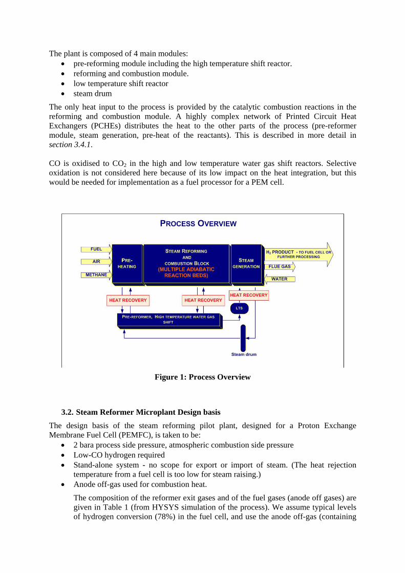
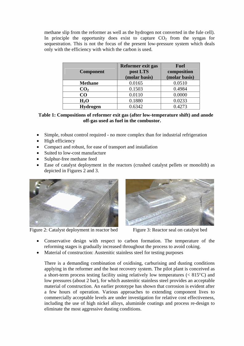
• Simple, robust control required - no more complex than for industrial refrigeration • High efficiency • Compact and robust, for ease of transport and installation • Suited to low-cost manufacture • Sulphur-free methane feed • Ease of catalyst deployment in the reactors (crushed catalyst pellets or monolith) as
depicted in Figures 2 and 3.
Figure 2: Catalyst deployment in reactor bed Figure 3: Reactor seal on catalyst bed
• Conservative design with respect to carbon formation. The temperature of the reforming stages is gradually increased throughout the process to avoid coking.
• Material of construction: Austenitic stainless steel for testing purposes
There is a demanding combination of oxidising, carburising and dusting conditions applying in the reformer and the heat recovery system. The pilot plant is conceived as a short-term process testing facility using relatively low temperatures (< 815°C) and low pressures (about 2 bar), for which austenitic stainless steel provides an acceptable material of construction. An earlier prototype has shown that corrosion is evident after a few hours of operation. Various approaches to extending component lives to commercially acceptable levels are under investigation for relative cost effectiveness, including the use of high nickel alloys, aluminide coatings and process re-design to eliminate the most aggressive dusting conditions.
3.3. Process intensification and scale up for distributed manufacturing
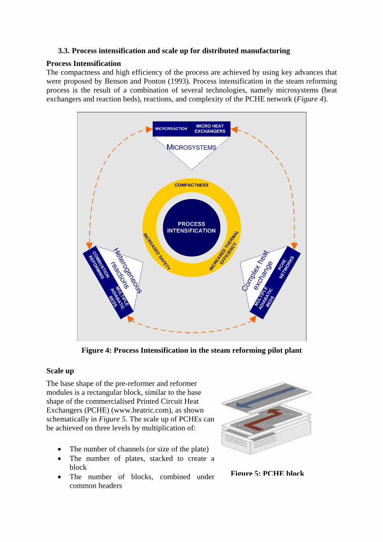
Process Intensification The compactness and high efficiency of the process are achieved by using key advances that were proposed by Benson and Ponton (1993). Process intensification in the steam reforming process is the result of a combination of several technologies, namely microsystems (heat exchangers and reaction beds), reactions, and complexity of the PCHE network (Figure 4).
Figure 4: Process Intensification in the steam reforming pilot plant
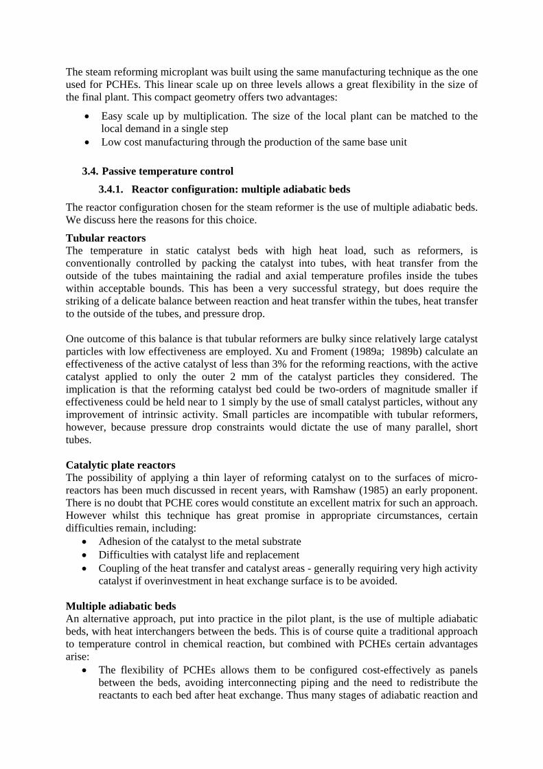
Scale up The base shape of the pre-reformer and reformer modules is a rectangular block, similar to the base shape of the commercialised Printed Circuit Heat Exchangers (PCHE) (www.heatric.com), as shown schematically in Figure 5. The scale up of PCHEs cbe achieved on three levels by multiplication of:
an
• The number of channels (or size of the plate) • The number of plates, stacked to create a
block • The number of blocks, combined under
common headers
Figure 5: PCHE block
The steam reforming microplant was built using the same manufacturing technique as the one used for PCHEs. This linear scale up on three levels allows a great flexibility in the size of the final plant. This compact geometry offers two advantages:
• Easy scale up by multiplication. The size of the local plant can be matched to the local demand in a single step
• Low cost manufacturing through the production of the same base unit
3.4. Passive temperature control
3.4.1. Reactor configuration: multiple adiabatic beds The reactor configuration chosen for the steam reformer is the use of multiple adiabatic beds. We discuss here the reasons for this choice.
Tubular reactors The temperature in static catalyst beds with high heat load, such as reformers, is conventionally controlled by packing the catalyst into tubes, with heat transfer from the outside of the tubes maintaining the radial and axial temperature profiles inside the tubes within acceptable bounds. This has been a very successful strategy, but does require the striking of a delicate balance between reaction and heat transfer within the tubes, heat transfer to the outside of the tubes, and pressure drop. One outcome of this balance is that tubular reformers are bulky since relatively large catalyst particles with low effectiveness are employed. Xu and Froment (1989a; 1989b) calculate an effectiveness of the active catalyst of less than 3% for the reforming reactions, with the active catalyst applied to only the outer 2 mm of the catalyst particles they considered. The implication is that the reforming catalyst bed could be two-orders of magnitude smaller if effectiveness could be held near to 1 simply by the use of small catalyst particles, without any improvement of intrinsic activity. Small particles are incompatible with tubular reformers, however, because pressure drop constraints would dictate the use of many parallel, short tubes. Catalytic plate reactors The possibility of applying a thin layer of reforming catalyst on to the surfaces of micro-reactors has been much discussed in recent years, with Ramshaw (1985) an early proponent. There is no doubt that PCHE cores would constitute an excellent matrix for such an approach. However whilst this technique has great promise in appropriate circumstances, certain difficulties remain, including:
• Adhesion of the catalyst to the metal substrate • Difficulties with catalyst life and replacement • Coupling of the heat transfer and catalyst areas - generally requiring very high activity
catalyst if overinvestment in heat exchange surface is to be avoided. Multiple adiabatic beds An alternative approach, put into practice in the pilot plant, is the use of multiple adiabatic beds, with heat interchangers between the beds. This is of course quite a traditional approach to temperature control in chemical reaction, but combined with PCHEs certain advantages arise:
• The flexibility of PCHEs allows them to be configured cost-effectively as panels between the beds, avoiding interconnecting piping and the need to redistribute the reactants to each bed after heat exchange. Thus many stages of adiabatic reaction and
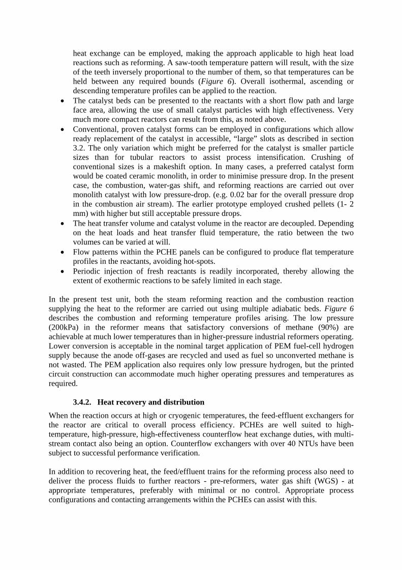
heat exchange can be employed, making the approach applicable to high heat load reactions such as reforming. A saw-tooth temperature pattern will result, with the size of the teeth inversely proportional to the number of them, so that temperatures can be held between any required bounds (Figure 6). Overall isothermal, ascending or descending temperature profiles can be applied to the reaction.
• The catalyst beds can be presented to the reactants with a short flow path and large face area, allowing the use of small catalyst particles with high effectiveness. Very much more compact reactors can result from this, as noted above.
• Conventional, proven catalyst forms can be employed in configurations which allow ready replacement of the catalyst in accessible, “large” slots as described in section 3.2. The only variation which might be preferred for the catalyst is smaller particle sizes than for tubular reactors to assist process intensification. Crushing of conventional sizes is a makeshift option. In many cases, a preferred catalyst form would be coated ceramic monolith, in order to minimise pressure drop. In the present case, the combustion, water-gas shift, and reforming reactions are carried out over monolith catalyst with low pressure-drop. (e.g. 0.02 bar for the overall pressure drop in the combustion air stream). The earlier prototype employed crushed pellets (1- 2 mm) with higher but still acceptable pressure drops.
• The heat transfer volume and catalyst volume in the reactor are decoupled. Depending on the heat loads and heat transfer fluid temperature, the ratio between the two volumes can be varied at will.
• Flow patterns within the PCHE panels can be configured to produce flat temperature profiles in the reactants, avoiding hot-spots.
• Periodic injection of fresh reactants is readily incorporated, thereby allowing the extent of exothermic reactions to be safely limited in each stage.
In the present test unit, both the steam reforming reaction and the combustion reaction supplying the heat to the reformer are carried out using multiple adiabatic beds. Figure 6 describes the combustion and reforming temperature profiles arising. The low pressure (200kPa) in the reformer means that satisfactory conversions of methane (90%) are achievable at much lower temperatures than in higher-pressure industrial reformers operating. Lower conversion is acceptable in the nominal target application of PEM fuel-cell hydrogen supply because the anode off-gases are recycled and used as fuel so unconverted methane is not wasted. The PEM application also requires only low pressure hydrogen, but the printed circuit construction can accommodate much higher operating pressures and temperatures as required.
3.4.2. Heat recovery and distribution
When the reaction occurs at high or cryogenic temperatures, the feed-effluent exchangers for the reactor are critical to overall process efficiency. PCHEs are well suited to high-temperature, high-pressure, high-effectiveness counterflow heat exchange duties, with multi-stream contact also being an option. Counterflow exchangers with over 40 NTUs have been subject to successful performance verification. In addition to recovering heat, the feed/effluent trains for the reforming process also need to deliver the process fluids to further reactors - pre-reformers, water gas shift (WGS) - at appropriate temperatures, preferably with minimal or no control. Appropriate process configurations and contacting arrangements within the PCHEs can assist with this.
Figure 6: Saw-tooth pattern for the temperature profile in the reforming and combustion module
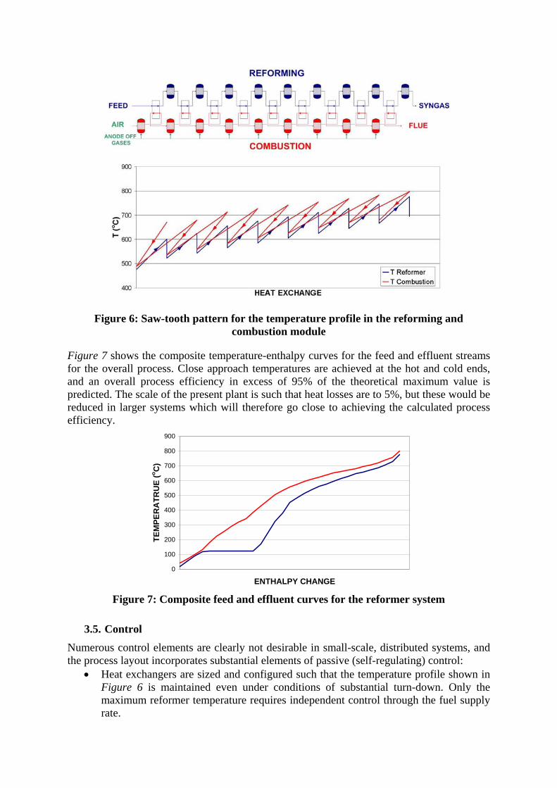
Figure 7 shows the composite temperature-enthalpy curves for the feed and effluent streams for the overall process. Close approach temperatures are achieved at the hot and cold ends, and an overall process efficiency in excess of 95% of the theoretical maximum value is predicted. The scale of the present plant is such that heat losses are to 5%, but these would be reduced in larger systems which will therefore go close to achieving the calculated process efficiency.
0
100
200
300
400
500
600
700
800
900
ENTHALPY CHANGE
TEM
PER
ATR
UE
(o C)
Figure 7: Composite feed and effluent curves for the reformer system
3.5. Control Numerous control elements are clearly not desirable in small-scale, distributed systems, and the process layout incorporates substantial elements of passive (self-regulating) control:
• Heat exchangers are sized and configured such that the temperature profile shown in Figure 6 is maintained even under conditions of substantial turn-down. Only the maximum reformer temperature requires independent control through the fuel supply rate.
• Counterflow and co-flow exchangers are employed. Both pinch up as flow rates fall, without substantially affecting boundary temperatures.
• The parallel splits in the fuel supply to the catalytic combustors are “hard-wired” into the assemblies, and require no active control.
• Water is supplied at the rate required to maintain level in the phase separator, from which there is a net outflow of process steam and a small liquid blow-down. The steam ratio remains reasonably constant with capacity as the availability of heat to raise steam varies with the methane throughput.
4. PLANT SET UP
4.1. Prototype Testing of the Compact Steam Reforming Technology A prototype version of the plant has been demonstrated successfully. The new plant incorporates a number of minor process design changes as well as improved layout of components on the etched plates to reduce complexity and minimise pressure drops. In addition, the pilot plant at the University of Sydney incorporates a high degree of instrumentation for systematic monitoring of all process variables. The testing of the plant is under way.
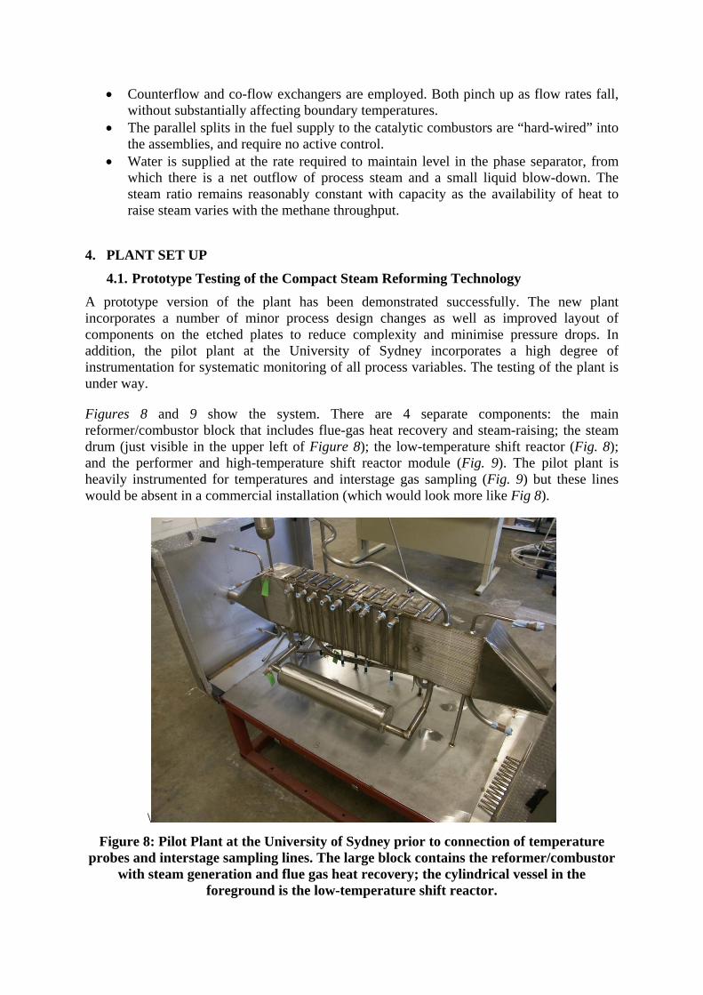
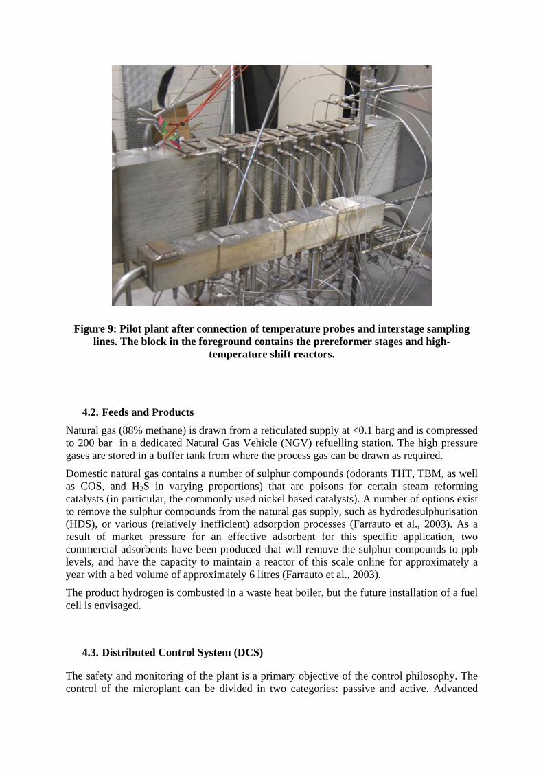
Figures 8 and 9 show the system. There are 4 separate components: the main reformer/combustor block that includes flue-gas heat recovery and steam-raising; the steam drum (just visible in the upper left of Figure 8); the low-temperature shift reactor (Fig. 8); and the performer and high-temperature shift reactor module (Fig. 9). The pilot plant is heavily instrumented for temperatures and interstage gas sampling (Fig. 9) but these lines would be absent in a commercial installation (which would look more like Fig 8).
\
Figure 8: Pilot Plant at the University of Sydney prior to connection of temperature probes and interstage sampling lines. The large block contains the reformer/combustor
with steam generation and flue gas heat recovery; the cylindrical vessel in the foreground is the low-temperature shift reactor.
Figure 9: Pilot plant after connection of temperature probes and interstage sampling lines. The block in the foreground contains the prereformer stages and high-
temperature shift reactors.
4.2. Feeds and Products Natural gas (88% methane) is drawn from a reticulated supply at <0.1 barg and is compressed to 200 bar in a dedicated Natural Gas Vehicle (NGV) refuelling station. The high pressure gases are stored in a buffer tank from where the process gas can be drawn as required.
Domestic natural gas contains a number of sulphur compounds (odorants THT, TBM, as well as COS, and H2S in varying proportions) that are poisons for certain steam reforming catalysts (in particular, the commonly used nickel based catalysts). A number of options exist to remove the sulphur compounds from the natural gas supply, such as hydrodesulphurisation (HDS), or various (relatively inefficient) adsorption processes (Farrauto et al., 2003). As a result of market pressure for an effective adsorbent for this specific application, two commercial adsorbents have been produced that will remove the sulphur compounds to ppb levels, and have the capacity to maintain a reactor of this scale online for approximately a year with a bed volume of approximately 6 litres (Farrauto et al., 2003).
The product hydrogen is combusted in a waste heat boiler, but the future installation of a fuel cell is envisaged.
4.3. Distributed Control System (DCS)
The safety and monitoring of the plant is a primary objective of the control philosophy. The control of the microplant can be divided in two categories: passive and active. Advanced
process control is not the aim of the study, as the high degree of passive control renders the system self-regulating. As previously described in section 4, heat management, through a judicious network of multiple adiabatic beds and PCHEs ensures the passive control of the process temperatures. The reactor section arrangement achieves a saw-tooth temperature pattern. The size of the “teeth” is inversely proportional to the number of them, so that temperatures can be held between any required bounds. The active control and monitoring of the pilot plant is ensured by a Centum CS3000 Distributed Control System (DCS) [Yokogawa Pty. Ltd.]. The DCS achieves three important functions:
• The monitoring of the pilot plant is necessary for the understanding of the fundamental phenomena occurring in the process. A history of the data is kept for time evolution studies. This source of information is significant to further process improvements.
• Reliable safety interlocks and alarms are implemented in the hazardous zone for the safety of operators and co-workers.
In detail, 35 temperatures, 22 online pressures, and 24 composition samples are collected during normal operation. The samples are analysed rapidly using micro gas chromatography. The gas supplies are measured and controlled with mass flow controllers. An air blower controls the air flow rate, and a pump controls the water circulation rate. Full heat and mass balances are available from these measurements.
4.4. Safety Safety is of primary concern in the installation of the pilot plant. Two studies were conducted to prevent and monitor any hazardous situation.
• A Hazard and Operability (HAZOP and CHAZOP) studies were conducted to specifically determine the hazardous events that could occur during operation. Actions were taken to prevent or reduce the likelihood of the identified hazards.
• A Hazardous Area Classification dossier was assembled for the compliance with Australian Standards. This study was conducted to put in place best work practices and suitable equipment for the safety of the operators. Suitable ventilation and suitable instrumentation were chosen. The ventilation system was in accordance with AS 1482. The instruments were chosen to match the hazardous zone classification requirements, which complied with AS/NZS 2340.3.4:1997. The Ex ia (intrinsic safety), Ex m (moulded) and Ex n (non-sparking) certifications were suitable for our application.
5. CONCLUSIONS The demonstration microplant responds to the need for distributed manufacturing in isolated economies such as Australia. Process intensification, realised through PCHE technology combined with reaction engineering, has permitted the manufacture of a highly integrated, highly compact system, offering increased safety, high efficiency and excellent scaleability.
The steam reforming pilot plant at the University of Sydney is a unique facility for research and demonstration in compact systems engineering and distributed chemicals manufacture.
6. REFERENCES Benson, R. S. and Ponton, J. W. (1993) Chemical Engineering Research & Design, 71, 160-
168. Ehrfeld, W., Hessel, V. and Löwe, H., Microreactors, (2000) Wiley-VCH, Weinheim.. Farrauto, R., Hwang, S., Shore, L., Ruettinger, W., Lampert, J., Giroux, T., Liu, Y. and
Ilinich, O. (2003) Annu. Rev. Mater. Res., 33, 1-27. Hessel, V., Hardt, S., and Löwe H, (2004), Chemical Micro Process Engineering-
Fundamenetals, Modelling and Reactions, Wiley-VCH, Weinheim. Hessel, V., Löwe H, Müller, A. and Kolb, G., (2005), Chemical Micro Process Engineering-
Processing and Plants, Wiley-VCH, Weinheim. Johnston, A.M., (1986), The Chemical Engineer, December, 36-38. Ramshaw, C., (1985), The Chemical Engineer, July/August, 30-33. Xu, J. and Froment, G. F. (1989a) AIChE Journal, 35, 88-96. Xu, J. and Froment, G. F. (1989b) AIChE Journal, 35, 97-103.