11
Publ. 2 - EN1702 - A 01 / 99 / 2500 / FB Replaces : DENISON HYDRAULICS high performance hydraulic new vane motor series M5B - M5BS - M5BF
Publ. 2 - EN1702 - A 01 / 99 / 2500 / FB Replaces :
DENISON HYDRAULICShigh performance hydraulic
new vane motorseries M5B - M5BS - M5BF
CHARACTERISTICS - M5B* SERIES
12 vanes and a patented cartridge design allow a very low noise level, whatever thespeed.
The M5B series has been designed especially for severe duty applications wich requirehigh pressure , high speed and low fluid lubricity.Max. pressure (intermittent) M5B* 012 to 036: 320 bar
M5B* 045 : 280 bar
Max. speed (intermittent, low loaded cond.) M5B* 012 - 018 : 6000 RPMM5B* 028 - 036 : 4000 RPMM5B* 045 : 3000 RPM
Up to 90 % overall at 320 bar.Vane motors begin life with a high volumetric efficiency, and maintain that efficiencythroughout their operating life.Vane pin holdout design improves the mechanical efficiency at low pressure.
The high starting torque efficiency of the vane type motors allows them to start underhigh load without pressure overshoots, jerks and high instantaneous horsepower loads.
This 12 vane type motor exhibits a very low torque ripple (typical ± 1,5%), even at lowspeeds.
The vane, rotor and cam ring are pressure balanced to increase life over the full speedrange. Double lip vanes reduce the sensitivity to fluid pollution.
Our precise manufacturing allows any component to be interchangeable.Rotating groups may be easily replaced to renew the motor or change the displacementto suit altered requirements for speed or torque.
The M5B-M5BS are bi-directional motors, externally drained.The M5BF, externally drained, is available in three types of rotation : bi-directional,clockwise, counter-clockwise.The M5BF1, internally drained, is available in two types of rotation : clockwise, andcounter-clockwise.
The uni-directional M5BF and M5BF1 are designed with an internal valve that allowssmooth dynamic braking, with a very simple hydraulic circuit and without risk ofmotor cavitation.
M5B - M5BS : Cylindrical keyed or splined shaft according to SAE J744, ISO 3019-2 orJ498b.These products are designed primarily for coaxial drives which do not impose axial orside loading on the shaft.
M5BF : A stiff taper or cylindrical keyed shaft and a high load capacity double ballbearing allow the direct mounting on shaft (fan, ...).
Mounting flange Ports Drain Shaft ends
M5BISO 3019-2
100 A2/B4 HW(2/4 bolts - Ø 100)
SAE 3/4"4 bolts
UNC or metric threads(ISO/DIS 6162
SAE J518c)
M18 x 1,5Keyed cyl. SAE "B"
orKeyed cyl. ISO E 25M
orSplined SAE "B"
M5BS SAE "B" J744c(2/4 bolts - Ø 101,6) M18 x 1,5
orSAE 9/16"M5BF Special mounting
(2 bolts - Ø 135)
Keyed taper non SAEKeyed cyl. SAE "C"
Keyed cyl. ISO G32N
LOW NOISE MOTOR
HIGH PERFORMANCE MOTOR
HIGH EFFICIENCY
HIGH STARTING TORQUE
LOW TORQUE RIPPLE
HIGH LIFETIME
INTERCHANGEABLE ROTATINGGROUPS
ROTATION AND DRAIN
CROSS PORT CHECK VALVE
MOUNTING
2
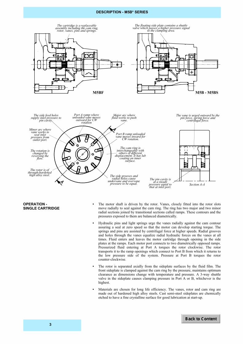
DESCRIPTION - M5B* SERIES
The floating side plate contains a shuttlevalve which passes a higher pressure signal
to the clamping area.The cartridge is a replaceable
assembly including the cam ring,rotor, vanes, pins and springs.
The vane is urged outward by thepin force, spring force and
centrifugal force.
Port A ramp whereunloaded vane moves
outward for CWrotation
Major arc wherefluid works to push
vane.
Port B ramp unloadedvane moves inward for
CW rotation.
Section A-AThe pin cavity is
at a steadypressure equal tothat at inlet port.
The cam ring isinterchangeable with
others of differentdisplacement. It has lub
coating on innersurface.
The side grooves andradial holes cause
undervane and overvanepressure to be equal.
The rotor is ofthrough-hardenedhigh alloy steel.
The rotation ischanged by
reversing theflow.
Minor arc wherevane works to
seal inletpressure from
outlet port.
The side feed holessupply inlet pressure to
pin cavity.
M5BF M5B - M5BS
• The motor shaft is driven by the rotor. Vanes, closely fitted into the rotor slotsmove radially to seal against the cam ring. The ring has two major and two minorradial sections joined by transitional sections called ramps. These contours and thepressures exposed to them are balanced diametrically.
• Hydraulic pins and light springs urge the vanes radially against the cam contourassuring a seal at zero speed so that the motor can develop starting torque. Thesprings and pins are assisted by centrifugal force at higher speeds. Radial groovesand holes through the vanes equalize radial hydraulic forces on the vanes at alltimes. Fluid enters and leaves the motor cartridge through opening in the sideplates at the ramps. Each motor port connects to two diametrically opposed ramps.Pressurized fluid entering at Port A torques the rotor clockwise. The rotortransports it to the ramp openings which connect to Port B from which it returns tothe low pressure side of the system. Pressure at Port B torques the rotorcounter-clockwise.
• The rotor is separated axially from the sideplate surfaces by the fluid film. Thefront sideplate is clamped against the cam ring by the pressure, maintains optimumclearance as dimensions change with temperature and pressure. A 3-way shuttlevalve in the sideplate causes clamping pressure in Port A or B, whichever is thehighest.
• Materials are chosen for long life efficiency. The vanes, rotor and cam ring aremade out of hardened high alloy steels. Cast semi-steel sideplates are chemicallyetched to have a fine crystalline surface for good lubrication at start-up.
OPERATION -SINGLE CARTRIDGE
3

PORTS AND HYDRAULIC FLUIDS - M5B* SERIES
This motor may be alternately pressurized on ports A and B to 320 bar max.Whichever port is at low pressure, it should not be subjected to more than 60% of thehigh pressure, eg : When 320 bar in A, B is limited to 200 bar.
This motor must have a drain line connected to the center housing drain connection ofsufficient size to prevent back pressure in excess of 3,5 bar, and returned to thereservoir below the surface of the oil as far away as possible from the suction pipe ofthe pump.
This unidirectional motor may be pressurized only on the port corresponding to itsrotation type.The outlet pressure must not be higher than 3,5 bar.
Petroleum base anti-wear R & O fluids (covered by DENISON HF-0 and HF-2specifications).Maximum catalog ratings and performance data are based on operation with thesefluids.
They are easily used in the M5B* motor. These include phosphate or organic esterfluids and blends, water-glycol solutions and water-oil invert emulsions.
The use of fluids other than petroleum base anti-wear R & O fluids requires that themaximum ratings of the motor will be reduced. In some cases, the minimumreplenishment pressure must be increased.
HF-1 : non antiwear petroleum base.HF-3 : water in oil emulsion.HF-4 : water glycols.HF-5 : synthetic fluids.Max. press. int. : 240 bar (HF-1, HF-4, HF-5) 175 bar (HF-3)Max. press. cont. : 210 bar (HF-1, HF-4, HF-5) 140 bar (HF-3)Max. speed : 1800 RPM (HF-3, HF-4, HF-5)
Max. (cold start, low speed and pressure)_______________________860 mm2/s (cSt)Max. (full speed and pressure) _______________________________100 mm2/s (cSt)Optimum (max. lifetime) ____________________________________30 mm2/s (cSt)Min. (full speed and pressure, HF-1 fluid) _______________________18 mm2/s (cSt)Min. (full speed and pressure, HF-0 & HF-2 fluids) _______________10 mm2/s (cSt)For cold starts, the motor should operate at low speed and pressure until fluid warmsup to an acceptable viscosity for full power operation.
90 min.Higher values extend the range of operating temperatures and lifetime.
Max. fluid temperature (HF-0, HF-1 & HF-2) _________________________+ 100° CMin. fluid temperature (HF-0, HF-1 &HF-2) ___________________________ - 18° C
The fluid must be cleaned before and during operation to maintain a contaminationlevel of NAS 1638 class 8 (or ISO 18/14) or better. Filters with 25 micron (or better, ß10 ≥100) nominal ratings may be adequate but do not guarantee the required cleanlinesslevels.
Maximum acceptable content of water is :• 0,10 % for mineral base fluids• 0,05 % for synthetic fluids, crankcase oils, biodegradable fluids.If amount of water is higher, then it should be drained off the circuit.
EXTERNAL DRAIN MOTOR
INTERNAL DRAIN MOTOR
RECOMMENDED FLUIDS
FIRE RESISTANT FLUIDS
ACCEPTABLE ALTERNATEFLUIDS
VISCOSITY
VISCOSITY INDEX
TEMPERATURE
FLUID CLEANLINESS
WATER CONTAMINATION INFLUID
MINIMUM REPLENISHMENT PRESSURE (BAR ABSOLUTE)
Speed [RPM] - Oil viscosity = 32 cSt500 1000 2000 3000 4000
M5B* 1,4 1,7 2,7 4,2 6.0
The inlet port of the motor must be supplied with replenishment pressure as listed above to prevent cavitation during dynamicbraking. This pressure should be multiplied by a coefficient of 1,5 when used with fire resistant fluids (HF-3, HF-4, HF-5).
4
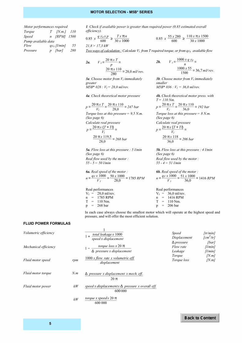
MOTOR SELECTION - M5B* SERIES
1. Check if available power is greater than required power (0.85 estimated overallefficiency).
0.85 x q Ve x p600 ≥
T x π n30 x 1000 0.85 x 55 x 280
600 ≥ 110 x π x 1500
30 x 100021,8 > 17,3 kWTwo ways of calculation : Calculate Vi from T required torque, or from qVe available flow
2a. V i = 20 π x T
p =
20 π x 110
280 = 28,0 ml ⁄ rev.
2b. V i = 1000 x q Ven =
1000 x 551500 = 36,7 ml ⁄ rev.
3a. Choose motor from Vi immediatelygreaterM5B* 028 : Vi = 28,0 ml/rev.
3b. Choose motor from Vi immediatelysmallerM5B* 036 : Vi = 36,0 ml/rev.
4a. Check theoretical motor pressure
p = 20 π x T
Vi = 20 π x 110
28,0 = 247 bar
Torque loss at this pressure = 9,5 N.m.(See page 6)
4b. Check theoretical motor press. withT = 110 Nm.
p = 20 π x T
Vi = 20 π x 110
36,0 = 192 bar
Torque loss at this pressure = 8 N.m.(See page 6)
Calculate real pressure
p = 20 π x (T + Tl)
Vi =
20 π x 119,5
28,0 = 268 bar
5a. Flow loss at this pressure : 5 l/min(See page 6)
Calculate real pressure
p = 20 π x (T + Tl)
Vi =
20 π x 118
36,0 = 206 bar
5b. Flow loss at this pressure : 4 l/min(See page 6)
Real flow used by the motor :55 - 5 = 50 l/min
Real flow used by the motor :55 - 4 = 51 l/min
6a. Real speed of the motor :
n = qV x 1000
V i = 50 x 1000
28,0 = 1785 RPM
6b. Real speed of the motor :
n = qV x 1000
V i = 51 x 1000
36,0 = 1416 RPM
Real performancesVi = 28,0 ml/rev.n = 1785 RPMT = 110 Nm.p = 268 bar
Real performancesVi = 36,0 ml/rev.n = 1416 RPMT = 110 Nm.p = 206 bar
In each case always choose the smallest motor which will operate at the highest speed andpressure, and will offer the most efficient solution.
FLUID POWER FORMULAS
Volumetric efficiency
Mechanical efficiency
Fluid motor speed rpm
Fluid motor torque N.m
Fluid motor power kW
kW
1
1 + total leakage x 1000speed x displacement
1 − torque loss x 20 π
∆ pressure x displacement
1000 x flow rate x volumetric eff.displacement
∆ pressure x displacement x mech. eff.20 π
speed x displacement x ∆ pressure x overall eff.600 000
torque x speed x 20 π600 000
Motor performances requiredTorque T [N.m.] 110Speed n [RPM] 1500Pump available dataFlow qVe [l/min] 55Pressure p [bar] 280
Speed [tr/min]Displacement [cm3/tr]∆ pressure [bar]Flow rate [l/min]Leakage [l/min]Torque [N.m]Torque loss [N.m]
5
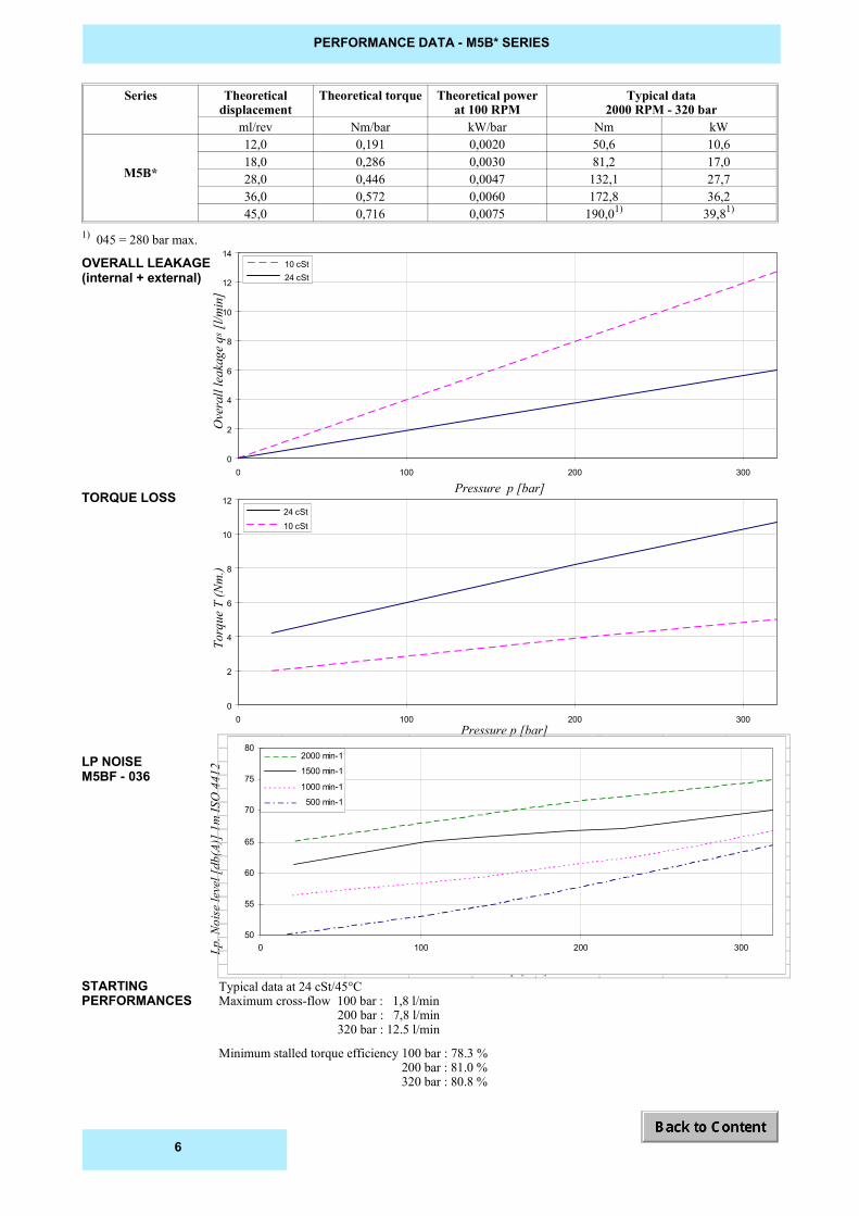
PERFORMANCE DATA - M5B* SERIES
Lp. N
oise
leve
l [db
(A)]
1m
ISO
441
2
Pressure p [bar]
Ove
rall
leak
age
qs [l
/min
]
Pressure p [bar]
Pressure p [bar]
OVERALL LEAKAGE(internal + external)
TORQUE LOSS
LP NOISEM5BF - 036
STARTINGPERFORMANCES
Torq
ue T
(Nm
.)
Typical data at 24 cSt/45°CMaximum cross-flow 100 bar : 1,8 l/min 200 bar : 7,8 l/min 320 bar : 12.5 l/min
Minimum stalled torque efficiency 100 bar : 78.3 % 200 bar : 81.0 % 320 bar : 80.8 %
50
55
60
65
70
75
80
0 100 200 300
2000 min-1
1500 min-1
1000 min-1
500 min-1
0
2
4
6
8
10
12
14
0 100 200 300
10 cSt 24 cSt
0
2
4
6
8
10
12
0 100 200 300
24 cSt 10 cSt
Series Theoreticaldisplacement
Theoretical torque Theoretical powerat 100 RPM
Typical data2000 RPM - 320 bar
ml/rev Nm/bar kW/bar Nm kW
M5B*
12,0 0,191 0,0020 50,6 10,618,0 0,286 0,0030 81,2 17,028,0 0,446 0,0047 132,1 27,736,0 0,572 0,0060 172,8 36,245,0 0,716 0,0075 190,01) 39,81)
1) 045 = 280 bar max.
6
Pres
sure
p [b
ar]
Operating speed n [RPM]
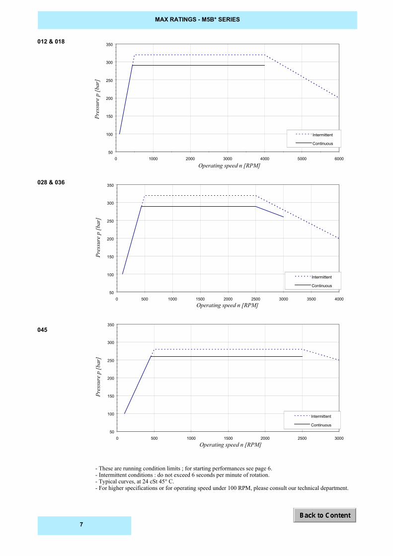
MAX RATINGS - M5B* SERIES
Pres
sure
p [b
ar]
Operating speed n [RPM]
Pres
sure
p [b
ar]
012 & 018
028 & 036
045
Operating speed n [RPM]
- These are running condition limits ; for starting performances see page 6.- Intermittent conditions : do not exceed 6 seconds per minute of rotation.- Typical curves, at 24 cSt 45° C.- For higher specifications or for operating speed under 100 RPM, please consult our technical department.
50
100
150
200
250
300
350
0 500 1000 1500 2000 2500 3000
Intermittent
Continuous
50
100
150
200
250
300
350
0 500 1000 1500 2000 2500 3000 3500 4000
Intermittent
Continuous
50
100
150
200
250
300
350
0 1000 2000 3000 4000 5000 6000
Intermittent
Continuous
7
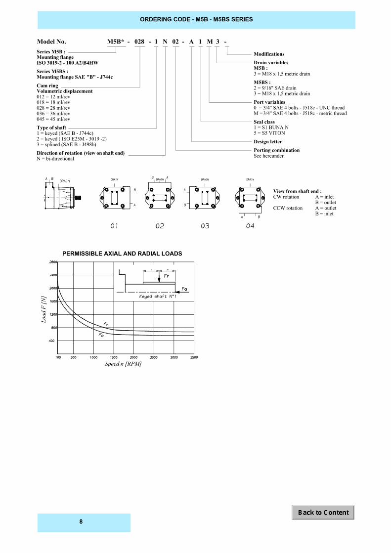
Model No. M5B* - 028 - 1 N 02 - A 1 M 3 - Series M5B :Mounting flangeISO 3019-2 - 100 A2/B4HWSeries M5BS :Mounting flange SAE "B" - J744cCam ringVolumetric displacement012 = 12 ml/rev018 = 18 ml/rev028 = 28 ml/rev036 = 36 ml/rev045 = 45 ml/revType of shaft1 = keyed (SAE B - J744c)2 = keyed ( ISO E25M - 3019 -2)3 = splined (SAE B - J498b)Direction of rotation (view on shaft end)N = bi-directional
ModificationsDrain variablesM5B :3 = M18 x 1,5 metric drainM5BS :2 = 9/16" SAE drain3 = M18 x 1,5 metric drainPort variables0 = 3/4" SAE 4 bolts - J518c - UNC threadM =3/4" SAE 4 bolts - J518c - metric threadSeal class1 = S1 BUNA N5 = S5 VITONDesign letterPorting combinationSee hereunder
ORDERING CODE - M5B - M5BS SERIES
Load
F [N
]
Speed n [RPM]
PERMISSIBLE AXIAL AND RADIAL LOADS
View from shaft end :CW rotation A = inlet
B = outletCCW rotation A = outlet
B = inlet
8

DIM
ENSIO
NS - W
eight : 18,5 kg - M5B
- M5B
S SERIES
M5B
MM10
3
M18 x 1,5
88,4
44,2
11,0
9,0
100,0
2,0
70,0
140,0
14,0
0
3/8" - 16 UNC
M5BS
MM10
3
M18 x 1,5
88,9
44,9
14,3
9,7
101,6
1,5
73,0
146,0
14,3
0
3/8" - 16 UNC
2
SAE9/16" - 18
Port codeØ A
Drain code
Ø B
C
D
Ø E
F
Ø G
H
J
K
Ø L
9
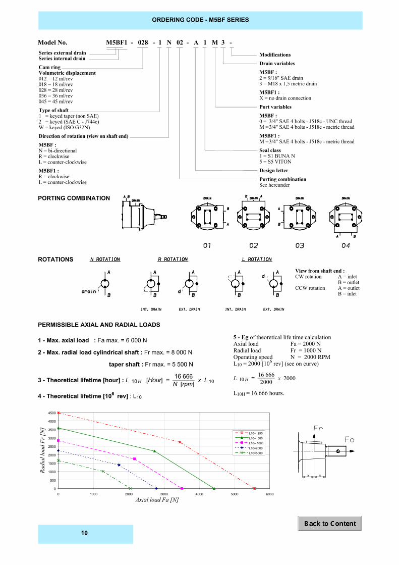
Model No. M5BF1 - 028 - 1 N 02 - A 1 M 3 - Series external drainSeries internal drainCam ringVolumetric displacement012 = 12 ml/rev018 = 18 ml/rev028 = 28 ml/rev036 = 36 ml/rev045 = 45 ml/revType of shaft1 = keyed taper (non SAE)2 = keyed (SAE C - J744c)W = keyed (ISO G32N)Direction of rotation (view on shaft end)M5BF :N = bi-directionalR = clockwiseL = counter-clockwiseM5BF1 :R = clockwiseL = counter-clockwise
ModificationsDrain variablesM5BF :2 = 9/16" SAE drain3 = M18 x 1,5 metric drainM5BF1 :X = no drain connectionPort variablesM5BF :0 = 3/4" SAE 4 bolts - J518c - UNC threadM =3/4" SAE 4 bolts - J518c - metric threadM5BF1 :M =3/4" SAE 4 bolts - J518c - metric threadSeal class1 = S1 BUNA N5 = S5 VITONDesign letterPorting combinationSee hereunder
ORDERING CODE - M5BF SERIES
Radi
al lo
ad F
r [N
]
Axial load Fa [N]
PERMISSIBLE AXIAL AND RADIAL LOADS
1 - Max. axial load : Fa max. = 6 000 N
2 - Max. radial load cylindrical shaft : Fr max. = 8 000 N
taper shaft : Fr max. = 5 500 N
3 - Theoretical lifetime [hour] : L 10 H [Hour] = 16 666N [rpm] x L 10
4 - Theoretical lifetime [106 rev] : L10
5 - Eg of theoretical life time calculationAxial load Fa = 2000 NRadial load Fr = 1000 NOperating speed N = 2000 RPML10 = 2000 [106 rev] (see on curve)
L 10 H = 16 6662000 x 2000
L10H = 16 666 hours.
PORTING COMBINATION
ROTATIONS
View from shaft end :CW rotation A = inlet
B = outletCCW rotation A = outlet
B = inlet
0
500
1000
1500
2000
2500
3000
3500
4000
4500
0 1000 2000 3000 4000 5000 6000
L10= 250L10= 500L10= 1000L10=2000L10=5000
10
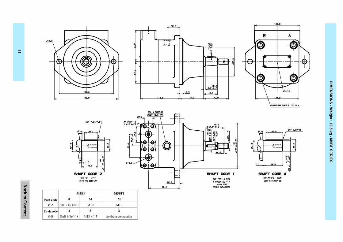
DIM
ENSIO
NS - W
eight : 18,5 kg - M5B
F SERIES
M5BF1
M
M10
X
no drain connection
M5BF
M
M10
3
M18 x 1,5
0
3/8" - 16 UNC
2
SAE 9/16"-18
Port codeØ A
Drain codeØ B
11


