DENSITY BASED TRAFFIC CONTROL USING
ARDUINO & IR SENSORS
A Project report submitted in partial fulfilment
of the requirements for the degree of B. Tech in Electrical Engineering
By
PRAVEEN RAI (11701615029)
PRABHAT KUMAR (11701615028)
NIKHIL KUMAR (11701615025)
PRITHWISH MONDAL (11701615031)
Under the supervision of
Mr. SUBHASISH BANDOPADHYAY
ASST. PROFESSOR
DEPARTMENT OF ELECTRICAL ENGINEERING
Department of Electrical Engineering
RCC INSTITUTE OF INFORMATION TECHNOLOGY
CANAL SOUTH ROAD, BELIAGHATA, KOLKATA – 700015, WEST BENGAL
Maulana Abul Kalam Azad University of Technology (MAKAUT)
© 2019
CERTIFICATE
To whom it may concern
This is to certify that the project work entitled DENSITY BASED TRAFFIC CONTROL
USING ARDUINO & IR SENSORS is the bona fide work carried out by PRAVEEN
RAI, PRABHAT KUMAR, NIKHIL KUMAR, PRITHWISH MONDAL a student of
B.Tech in the Dept. of Electrical Engineering, RCC Institute of Information
Technology (RCCIIT), Canal South Road, Beliaghata, Kolkata-700015, affiliated to
Maulana Abul Kalam Azad University of Technology (MAKAUT), West Bengal, India,
during the academic year 2018-19, in partial fulfillment of the requirements for the
degree of Bachelor of Technology in Electrical Engineering and that this project has
not submitted previously for the award of any other degree, diploma and fellowship.
_____________________ ________________________
Signature of the Guide Signature of the HOD
Name: SUBHASISH BANDOPADHYAY Name: DEBASISH MONDAL
Designation: ASST. PROFESSOR Designation: PROFESSOR & HOD
___________________________
Signature of the External Examiner
Name:
Designation:
ACKNOWLEDGEMENT
It is my great fortune that I have got opportunity to carry out this project work under the supervision
of Mr. SUBHASISH BANDOPADHYAY in the Department of Electrical Engineering, RCC Institute of
Information Technology (RCCIIT), Canal South Road, Beliaghata, Kolkata-700015, affiliated to Maulana
Abul Kalam Azad University of Technology (MAKAUT), West Bengal, India. I express my sincere thanks
and deepest sense of gratitude to my guide for his constant support, unparalleled guidance and
limitless encouragement.
I wish to convey my gratitude to Prof. (Dr.) Debasish Mondal, HOD, Department of Electrical
Engineering, RCCIIT and to the authority of RCCIIT for providing all kinds of infrastructural facility
towards the research work.
I would also like to convey my gratitude to all the faculty members and staffs of the Department
of Electrical Engineering, RCCIIT for their whole hearted cooperation to make this work turn into
reality.
Place : …………………………………
Date: Praveen Rai
Roll - 11701615029
…………………………………
Prabhat Kumar
Roll - 11701615028
……………………………. .......
Nikhil Kumar
Roll – 11701615025
… ……………………………….
Prithwish Mondal
Roll - 11701615031
ABSTRACT
The project is aimed at designing a density based dynamic traffic signal system where the
timing of signal will change automatically on sensing the traffic density at any junction.
Traffic congestion is a severe problem in most cities across the world and therefore it is
time to shift more manual mode or fixed timer mode to an automated system with decision
making capabilities.
Present day traffic signalling system is fixed time based which may render inefficient if
one lane is operational than the others. To optimize this problem we have made a framework
for an intelligent traffic control system. Sometimes higher traffic density at one side
of the junction demands longer green time as compared to standard allotted time We,
therefore propose here a mechanism in which the time period of green light and
red light is assigned on the basis of the density of the traffic present at that time. This
is achieved by using PIR (proximity Infrared sensors). Once the density is calculated,
the glowing time of green light is assigned by the help of the microcontroller (Arduino).
The sensors which are present on sides of the road will detect the presence of the
vehicles and sends the information to the microcontroller(Arduino) where it will decide
how long a flank will be open or when to change over the signal lights. In subsequent
sections, we have elaborated the procedure of this framework.
I N D E X
SERIAL
NO ITEMS/CONTENTS
PAGE
NO
01
INTRODUCTION
OBJECTIVE OF THE PROJECT
MOTIVATION FOR PROJECT
01
02 PRESENT TRAFFIC SIGNALLING SYSTEM 03
03 BLOCK DIAGRAM 04
04 POWER SUPPLY
RECTIFIER 05
05
LIST OF COMPONENTS USED
ARDUINO UNO
TRANSFORMER
SERIAL TO PARALLEL IC
VOLTAGE REGULATOR
CAPACITOR
DIODE
LEDS
CONNECTING WIRE
08
06
CIRCUIT DIAGRAM
CIRCUIT ON BREADBOARD
CIRCUIT ON VEROBOARD
18
07 SURVEY 21
08 WORKING 22
09 PROJECT CODE 25
10 RESULTS AND DISCUSSION 31
11 CHALLENGES AND FUTURE SCOPE 32
12 CONCLUSIONS 33
13 REFERENCES 34
[1]
INTRODUCTION
In today’s high speed life, traffic congestion becomes a serious issue in our day to day
activities. It brings down the productivity of individual and thereby the society as lots of work
hour is wasted in the signals. High volume of vehicles, the inadequate infrastructure and the
irrational distribution of the signalling system are main reasons for this chaotic congestions.
It indirectly also adds to the increase in pollution level as engines remain on in most
cases, a huge volume of natural resources in forms of petrol and diesel is consumed
without any fruitful outcome. Therefore, in order to get rid of these problems or at least reduce
them to significant level, newer schemes need to be implemented by bringing in sensor
based automation technique in this field of traffic signalling system.
OBJECTIVE OF THE PROJECT :
Our project aims at reducing traffic congestion and unwanted long time delay during the
traffic light switch overs especially when the traffic is very low.
It is designed to be implemented in places nearing the junctions where the traffic signals are
placed, in order to reduce the congestion in these junctions.
It keeps a track of the vehicles in each road and accordingly adjusts the time for each traffic
light signals.
The higher the number of vehicles on the road the longer will be the time delay allotted for
that corresponding traffic light signal.
The main purpose of this project is, if there will be no traffic on the other signal, one
shouldn’t wait for that signal. The system will skip that signal and will move on the next
one.
[2]
MOTIVATION FOR PROJECT
This is our final year project, which will draw attention of all the faculties. So, I want to make
a project through which everyone can relate to it. Also in our day to day life I am always
observing at the crossing of roads that in some lane there are lot of traffic compared to others
lane but all the signals in our country is timing based .So we cannot manage our time. Also due
to timing based the lighter dense roads are sometimes empty due to which many people start
crossing the road but due green signal in that lane vehicle moves at high speed which increases
the risk of accident.
So, the best solution of these problem is to make traffic control system which control the whole
traffic by density. From this we got the motivation to work on this project.
At the starting of the project we were not able to visualize it practically, but slowly we are
getting information from the Internet and taking help of some of our faculties of our college to
implement it practically. Any random person won’t be able to visualize our efforts put in the
completion of the project because after completion it looks a bit easy.
Our mentor and Sujoy sir played a very important role in the completion of our project. Without
their help we won’t be able to complete it properly. So, special thanks to our mentor and Sujoy
sir.
[3]
PRESENT TRAFFIC SIGNALING SYSTEM
Under present scenario, traffic control is achieved by the use of a system of hand signs by
traffic police personnel, traffic signals, and markings. A comparable and matching education
program is needed, through driver-licensing authorities, to assure that those who operate motor
vehicles understand the rules of the road and the actions that they are required or advised to
take when a particular control device is present. Each traffic control device is governed by
standards of design and usage; for example, stop signs always have a red background and are
octagonal in shape.
Design standards allow the motorist to quickly and consistently perceive the sign in the visual
field along the road. Standard use of colours and shape aids in this identification and in deciding
on the appropriate course of action. Under current circumstances, traffic lights are set on in the
different directions with fixed time delay, following a particular cycle while switching from
one signal to other creating unwanted and wasteful congestion on one lane while the other lanes
remain vacant.
The system we propose identify the density of traffic on individual lanes and thereby regulate
the timing of the signals’ timing. IR sensors count the obstructions and provide an idea about
the traffic density on a particular lane and feed this response to a controller unit which will
make the necessary decisions as and when required.
[4]
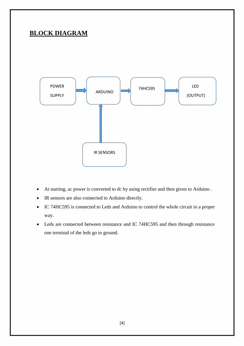
BLOCK DIAGRAM
At starting, ac power is converted to dc by using rectifier and then given to Arduino .
IR sensors are also connected to Arduino directly.
IC 74HC595 is connected to Leds and Arduino to control the whole circuit in a proper
way.
Leds are connected between resistance and IC 74HC595 and then through resistance
one terminal of the leds go to ground.
POWER
SUPPLY
ARDUINO 74HC595 LED
(OUTPUT)
IR SENSORS
[5]
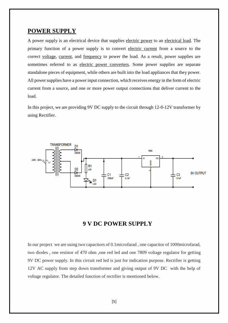
POWER SUPPLY
A power supply is an electrical device that supplies electric power to an electrical load. The
primary function of a power supply is to convert electric current from a source to the
correct voltage, current, and frequency to power the load. As a result, power supplies are
sometimes referred to as electric power converters. Some power supplies are separate
standalone pieces of equipment, while others are built into the load appliances that they power.
All power supplies have a power input connection, which receives energy in the form of electric
current from a source, and one or more power output connections that deliver current to the
load.
In this project, we are providing 9V DC supply to the circuit through 12-0-12V transformer by
using Rectifier.
9 V DC POWER SUPPLY
In our project we are using two capacitors of 0.1microfarad , one capacitor of 1000microfarad,
two diodes , one resistor of 470 ohm ,one red led and one 7809 voltage regulator for getting
9V DC power supply. In this circuit red led is just for indication purpose. Rectifier is getting
12V AC supply from step down transformer and giving output of 9V DC with the help of
voltage regulator. The detailed function of rectifier is mentioned below.
[6]
RECTIFIER
A rectifier is an electrical device that converts alternating current (AC), which periodically
reverses direction, to direct current (DC), which flows in only one direction. Rectifier circuits
may be single-phase or multi-phase (three phase being the most common number of phases).
Most low power rectifiers for domestic equipment are single-phase, but three-phase
rectification is very important for industrial applications and for the transmission of energy as
DC (HVDC).
Single-phase rectifier:
Half-wave rectification:
In half-wave rectification of a single-phase supply, either the positive or negative half of the
AC wave is passed, while the other half is blocked.
The no-load output DC voltage of an ideal half-wave rectifier for a sinusoidal input voltage is:
where:
Vdc, Vav – the DC or average output voltage,
Vpeak, the peak value of the phase input voltages,
Vrms, the root mean square (RMS) value of output voltage.
[7]
Full-wave rectification:
A full-wave rectifier converts the whole of the input waveform to one of constant polarity
(positive or negative) at its output. Mathematically, this corresponds to the absolute
value function. Full-wave rectification converts both polarities of the input waveform to
pulsating DC (direct current), and yields a higher average output voltage.
The average and RMS no-load output voltages of an ideal single-phase full-wave rectifier
are:
[8]
LIST OF COMPONENTS USED
1.ARDUINO UNO
2.TRANSFORMER (12-0-12)
3.IC 74HC595
(serial to parallel)
4.CAPACITOR
(0.1 microfarad-------2
1000 microfarad--------1)
5.DIODE
(1N4007--------2)
6.RESISTORS
(470 ohm---------13)
7.VOLTAGE REGULATOR
(IC 7809---------1)
8.LEDS
(green--------3
Yellow--------3
Red--------4)
9.CONNECTING WIRES
(As per required)
[9]
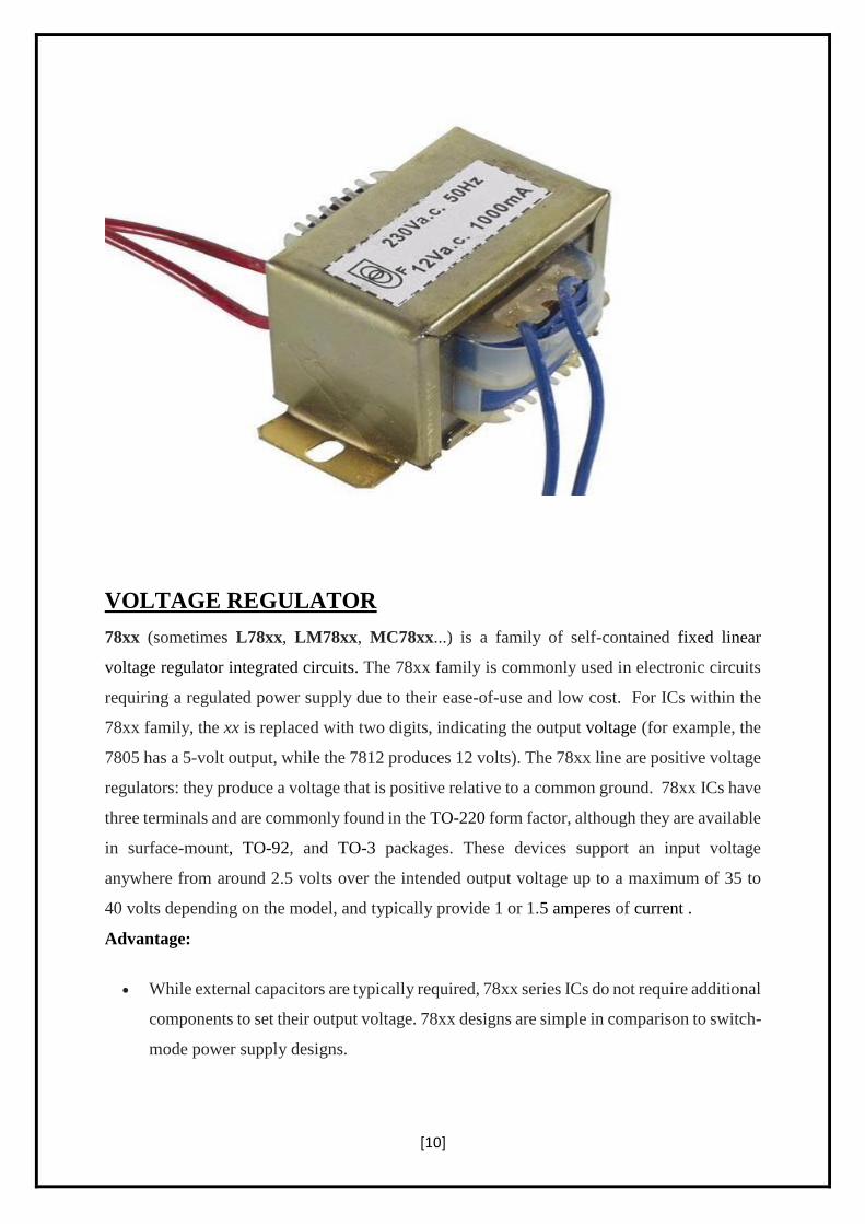
TRANSFORMER
Transformers are able to work in two regimes, as voltage step-up and voltage step-down
transformers. A step-down transformer converts the high voltage (HV) and low current from
the primary side to the low voltage (LV) and high current value on the secondary side. This
transformer type has a wide application in electronic devices and electrical systems. The first
LV application refers to the transformers in electronic devices. Supplying the electronic circuits
requires a low voltage value (e.g. 5V, even lower values nowadays). A step down transformer
is used to provide this low voltage value which is suitable for electronics supplying. If
electronic devices are designed to have higher nominal power, transformers with high operating
frequency are used (kHz-s). The transformers with higher nominal power value and 50/60 Hz
nominal frequency would be too large and heavy. Also, the daily used battery chargers use the
step-down transformer in its design.
[10]
VOLTAGE REGULATOR
78xx (sometimes L78xx, LM78xx, MC78xx...) is a family of self-contained fixed linear
voltage regulator integrated circuits. The 78xx family is commonly used in electronic circuits
requiring a regulated power supply due to their ease-of-use and low cost. For ICs within the
78xx family, the xx is replaced with two digits, indicating the output voltage (for example, the
7805 has a 5-volt output, while the 7812 produces 12 volts). The 78xx line are positive voltage
regulators: they produce a voltage that is positive relative to a common ground. 78xx ICs have
three terminals and are commonly found in the TO-220 form factor, although they are available
in surface-mount, TO-92, and TO-3 packages. These devices support an input voltage
anywhere from around 2.5 volts over the intended output voltage up to a maximum of 35 to
40 volts depending on the model, and typically provide 1 or 1.5 amperes of current .
Advantage:
While external capacitors are typically required, 78xx series ICs do not require additional
components to set their output voltage. 78xx designs are simple in comparison to switch-
mode power supply designs.
[11]
78xx series ICs have built-in protection against a circuit drawing too much current. They
have protection against overheating and short-circuits, making them robust in most
applications.
Disadvantage:
The input voltage must always be higher than the output voltage by some minimum amount.
As they are based on a linear regulator design, the input current required is always the same as
the output current.
DIODE
The most common function of a diode is to allow an electric current to pass in one direction
(called the diode's forward direction), while blocking it in the opposite direction
(the reverse direction). diodes can have more complicated behaviour than this simple on–off
action, because of their nonlinear current-voltage characteristics. Semiconductor diodes begin
conducting electricity only if a certain threshold voltage or cut-in voltage is present in the
forward direction. The voltage drop across a forward-biased diode varies only a little with the
current, and is a function of temperature; this effect can be used as a temperature sensor or as
a voltage reference.
[12]
CAPACITOR
A capacitor is a passive two-terminal electronic component that stores electrical energy in
an electric field. The effect of a capacitor is known as capacitance. While some capacitance
exists between any two electrical conductors in proximity in a circuit, a capacitor is a
component designed to add capacitance to a circuit.
An ideal capacitor is characterized by a constant capacitance C, in farads in the SI system of
units, defined as the ratio of the positive or negative charge Q on each conductor to the
voltage V between them:
A capacitance of one farad (F) means that one coulomb of charge on each conductor causes
a voltage of one volt across the device.
[13]
ARDUINO
The Arduino UNO is an open-source microcontroller board based on
the Microchip ATmega328P microcontroller. The board is equipped with sets of digital and
analog input/output (I/O) pins that may be interfaced to various expansion boards (shields) and
other circuits. The board has 14 Digital pins, 6 Analog pins, and programmable with
the Arduino IDE (Integrated Development Environment) via a type B USB cable. It can be
powered by a USB cable or by an external 9 volt battery, though it accepts voltages between 7
and 20 volts. "Uno" means one in Italian and was chosen to mark the release of Arduino
Software (IDE) 1.0.The Uno board and version 1.0 of Arduino Software (IDE) were the
reference versions of Arduino, now evolved to newer releases. The Uno also differs from all
preceding boards in that it does not use the FTDI USB-to-serial driver chip. Instead, it uses the
Atmega16U2 (Atmega8U2 up to version R2) programmed as a USB-to-serial converter.
[14]
General Pin functions:
LED: There is a built-in LED driven by digital pin 13. When the pin is HIGH value, the
LED is on, when the pin is LOW, it's off.
VIN: The input voltage to the Arduino/Genuino board when it's using an external power
source (as opposed to 5 volts from the USB connection or other regulated power source).
You can supply voltage through this pin, or, if supplying voltage via the power jack,
access it through this pin.
5V: This pin outputs a regulated 5V from the regulator on the board. The board can be
supplied with power either from the DC power jack (7 - 20V), the USB connector (5V),
or the VIN pin of the board (7-20V). Supplying voltage via the 5V or 3.3V pins bypasses
the regulator, and can damage the board.
3V3: A 3.3 volt supply generated by the on-board regulator. Maximum current draw is
50 mA.
GND: Ground pins.
IOREF: This pin on the Arduino/Genuino board provides the voltage reference with
which the microcontroller operates. A properly configured shield can read the IOREF
pin voltage and select the appropriate power source or enable voltage translators on the
outputs to work with the 5V or 3.3V.
Reset: Typically used to add a reset button to shields which block the one on the board.
TECHNICAL SPECIFICATIONS:
Microcontroller: Microchip ATmega328P
Operating Voltage: 5 Volts
Input Voltage: 7 to 20 Volts
Digital I/O Pins: 14 (of which 6 provide PWM output)
Analog Input Pins: 6
DC Current per I/O Pin: 20 mA
DC Current for 3.3V Pin: 50 mA
Flash Memory: 32 KB of which 0.5 KB used by bootloader
SRAM: 2 KB
EEPROM: 1 KB
Clock Speed: 16 MHz
Length: 68.6 mm
Width: 53.4 mm
Weight: 25 g
[15]
IC 74HC595
The 74HC595 is a very handy IC used in many microcontroller projects. The clock in 8 bits of
data (like, on/off settings for 8 LEDs) via two lines, and when you toggle a third line, it pops
these settings out on 8 outputs on the IC. So you trade 3 valuable lines on your microcontroller
for 8 outputs .
This is called "Shifting data out" of the microcontroller by "synchronous serial
communication". This is the serial part of the deal, where each bit is "shifted in" one at a time,
then BOOM, they all appear at once (in parallel) on the chips output.
There are some great tutorials on how to use a shift register. Here's one for the Arduino
microcontroller, but the technique holds true for pretty much all microcontrollers!
SPECIFICATIONS:
8-bit
Logic Family : HC
Logical Function : Shift Register
Operating Supply Voltage (Typ) : 5V
Output Type : 3-State
Package Type : DIP
Propagation Delay Time : 265ns
Operating Temp Range : -40C to 125C
Operating Supply Voltage (Min) : 2V
Operating Supply Voltage (Max) : 6V
[16]
IR SENSORS
An infrared sensor is an electronic device, which emits in order to sense some aspects of the
surroundings. An IR sensor can measure the heat of an object as well as detects the
motion. Usually in the infrared spectrum, all the objects radiate some form of thermal
radiations. These types of radiations are invisible to our eyes , that can be detected by an
infrared sensor. The emitter is simply an IR LED (Light Emitting Diode) and the detector is
simply an IR photodiode which is sensitive to IR light of the same wavelength as that emitted
by the IR LED.
LM358 IC 2 IR transmitter and receiver pair
Resistors of the range of kilo ohms.
Variable resistors.
LED (Light Emitting Diode).
In this project, the transmitter section includes an IR sensor, which transmits continuous IR
rays to be received by an IR receiver module. An IR output terminal of the receiver varies
depending upon its receiving of IR rays. Since this variation cannot be analysed as such,
therefore this output can be fed to a comparator circuit. Here an operational amplifier (op-amp)
of LM 339 is used as comparator circuit.
When the IR receiver does not receive a signal, the potential at the inverting input goes higher
than that non-inverting input of the comparator IC (LM339). Thus the output of the comparator
goes low, but the LED does not glow. When the IR receiver module receives signal to the
potential at the inverting input goes low. Thus the output of the comparator (LM 339) goes
high and the LED starts glowing.
[17]
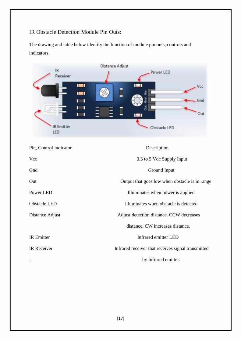
IR Obstacle Detection Module Pin Outs:
The drawing and table below identify the function of module pin outs, controls and
indicators.
Pin, Control Indicator Description
Vcc 3.3 to 5 Vdc Supply Input
Gnd Ground Input
Out Output that goes low when obstacle is in range
Power LED Illuminates when power is applied
Obstacle LED Illuminates when obstacle is detected
Distance Adjust Adjust detection distance. CCW decreases
distance. CW increases distance.
IR Emitter Infrared emitter LED
IR Receiver Infrared receiver that receives signal transmitted
. by Infrared emitter.
[18]
CIRCUIT DIAGRAM
NOTE:
Dot present in the circuit is representing the connection between two wires.
S1, S2, S3 and S4 are representing the IR sensors.
R1,R2,R3,R4,R5,R6,R7,R8,R9,R10,R11 and R12 are representing the resistors.
R1, R2 and R3 are representing red light.
Y1, Y2 and Y3 are representing yellow light.
G1, G2 and G3 are representing green light.
[19]
CIRCUIT ON BREADBOARD
[20]
CIRCUIT ON VEROBOARD
[21]
SURVEY
Road infrastructure has seen consistent improvement in the last few years. Connectivity has
improved and road transportation has become a focus of rapid development. Roads are
providing better access to services, ease of transportation and freedom of movement to people.
But in metropolitan cities traffic congestion is increasing rapidly, it results in chronic situation
in dense downtown areas.
Traffic signals play a significant role in the urban transportation system. They control the
movement of traffic on urban streets by determining the appropriate signal timing settings.
Adaptive traffic signal controllers as the principle part of intelligent transportation systems has
a primary role to effectively reduce traffic congestion by making a real time adaptation in
response to the changing traffic network dynamics.
Many methods used for traffic signal timing optimization under different criteria's. In this paper
different methods are proposed by reviewing different research papers for traffic signal control,
which gives best adaptability & optimization ideas in traffic signal control.
[22]
WORKING OF THE CIRCUIT
The model works on the principle of changing of Traffic signals based on the density through
an assigned section of the road. There are four sensors placed at four sides of a four way road
which checks the density of the area covered by the sensors.
Here we are using IR sensors to design an intelligent traffic control system. In order to measure
the density of traffic on each side, IR sensors will be kept on either sides of the road at a specific
distance. Each of the IR sensors consists of an IR transmitter and an IR receiver. Just as the
name suggests, the IR transmitter transmits the IR rays and the receiver is responsible to receive
the rays. The whole system is controlled by the microcontroller which is the Aurdino. Arduino
is interfaced with Serial to parallel IC(74HC595) and IR sensors .As the vehicle passes through
these IR sensors, the IR sensor will detect the vehicle & will send the information to the
Arduino. The total no of IR sensors required are 4 and Led’s 12 .
Three sets of LEDs via Green, Yellow and Red are used to indicate the GO state, Ready to Go
state and WAIT state. The traffic signal will be tuned with a default timing of 10 seconds of
green light and all other signal will be red. After 10 seconds two signals will be yellow for 4
seconds and another two will be red. This condition will be followed till all the IR sensors
receiving the signals or all the IR sensors are not getting signals. The LEDs G (green), Y
(yellow) and R (red) glow in following sequence.
G1-R2-R3-R4
Y1-Y2-R3-R4
R1-G2-R3-R4
R1-Y2-Y3-R4.
R1-R2-G3-R4
R1-R2-Y3-Y4
R1-R2-R3-G4
Y1-R2-R3-Y4
i.e., timing based traffic signal will be automatically implemented when all the signals
having same condition.
[23]
When condition changes, Let us suppose when first side traffic signal is green and at that time
third side traffic signal’s IR sensor receiving data then after first traffic signal it will
automatically shifts towards third traffic signal without moving to second traffic signal.
G1-R2-R3-R4
Y1-R2-Y3-R4
R1-R2-G3-R4
Similarly, Let green light is On in the fourth traffic signal for 10 seconds and during that time
second traffic signal’s IR sensor receiving data then after green light it will take 4 seconds
delay for yellow light or we can say that the delay for pedestrians to walk in order to ensure
their safety and then it will automatically shifts towards second traffic signal.
R1-R2-R3-G4
R1-Y2-R3-Y4
R1-G2-R3-R4
Just taking into consideration the above conditions more further and let us suppose after second
signal again forth signal’s IR sensor receiving data then after 10 seconds and 4 seconds delay
signal is green for forth lane.
R1-G2-R3-R4
R1-Y2-R3-Y4
R1-R2-R3-G4
NOTE:
The working of the project is divided into three steps:
If there is traffic at all the signals, then the system will work normally by controlling the signals
one by one.
If there is no traffic near a signal, then the system will skip this signal and will move on to the
next one. For example, if there is no vehicle at signal 2, 3 and currently the system is allowing
vehicles at signal 1 to pass. Then after signal 1, the system will move on to signal 4 skipping
signal 2 and 3.
If there is no traffic at all the 4 signals, then also the system will work normally by controlling
the signals one by one.
[24]
In this way we can control the heavy traffic of any particular lane in peak timing like office
hour.
But, it has some very big drawbacks in which one of the drawback is the lane in which traffic
is low have to wait for long time.
[25]
CODE SECTION:
# define NOP __asm__("nop")
// LED pattern
unsigned int pattern = 0b0001000100010010; // RED | RED | RED | GR
unsigned int maskPattern[4] = {0xFFF0,0xFF0F,0xF0FF,0x0FFF};
// Sensor variables
int presentSensorId = 0; // Initial value
int nextSensorId = 1; // Initial value
int sensorCount = 4;
// Time constants
const long greenDelay = 10000; // 10 sec
const long yellowDelay = 4000; // 4 sec
// Sensor Pins
int sensorPin[4] = {A0,A1,A2,A3};
// SHR control
int SER = 2;
int RST = 3;
int inClk = 4;
int outClk = 5;
//*************************************************************************
void init_Port(){
pinMode(sensorPin[0],INPUT);
pinMode(sensorPin[1],INPUT);
pinMode(sensorPin[2],INPUT);
pinMode(sensorPin[3],INPUT);
[26]
}
//*************************************************************************
void init_Light(){
pinMode(SER,OUTPUT);
pinMode(RST,OUTPUT);
pinMode(inClk,OUTPUT);
pinMode(outClk,OUTPUT);
digitalWrite(SER,LOW);
digitalWrite(RST,LOW);
digitalWrite(inClk,LOW);
digitalWrite(outClk,LOW);
delay(500);
digitalWrite(inClk,HIGH);
delay(10);
digitalWrite(outClk,HIGH);
delay(10);
digitalWrite(inClk,LOW);
NOP;
digitalWrite(outClk,LOW);
digitalWrite(RST,HIGH);
}
//*************************************************************************
[27]
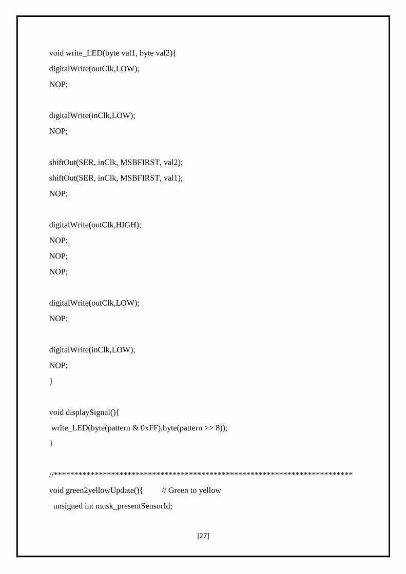
void write_LED(byte val1, byte val2){
digitalWrite(outClk,LOW);
NOP;
digitalWrite(inClk,LOW);
NOP;
shiftOut(SER, inClk, MSBFIRST, val2);
shiftOut(SER, inClk, MSBFIRST, val1);
NOP;
digitalWrite(outClk,HIGH);
NOP;
NOP;
NOP;
digitalWrite(outClk,LOW);
NOP;
digitalWrite(inClk,LOW);
NOP;
}
void displaySignal(){
write_LED(byte(pattern & 0xFF),byte(pattern >> 8));
}
//*************************************************************************
void green2yellowUpdate(){ // Green to yellow
unsigned int musk_presentSensorId;
[28]
unsigned int musk_nextSensorId;
pattern = 0b0001000100010001; // Default make all red then change
musk_presentSensorId = maskPattern[presentSensorId];
musk_nextSensorId = maskPattern[nextSensorId];
pattern = pattern & musk_presentSensorId;
pattern = pattern | (0b0100 << presentSensorId*4); // Load yellow pattern
pattern = pattern & musk_nextSensorId;
pattern = pattern | (0b0100 << nextSensorId*4); // Load yellow pattern
}
//*************************************************************************
void yellow2greenUpdate(){ // Yellow to green rest are RED
unsigned int musk_nextSensorId;
pattern = 0b0001000100010001; // Default make all red then change
musk_nextSensorId = maskPattern[nextSensorId];
pattern = pattern & musk_nextSensorId;
pattern = pattern | (0b0010 << nextSensorId*4); // Load green pattern
}
//*************************************************************************
void sensorIdUpdate(){
int I;
int busyFlag = 0; // reset value
[29]
// Checking next sensors
for (I=presentSensorId;I<sensorCount;I++){
if ((I!=presentSensorId) && (digitalRead(sensorPin[I]) == LOW)){
nextSensorId = I;
busyFlag = 1;
break;
}
}
// Checking previous sensors
if (busyFlag == 0){ // No busy road found
// Checking previous sensors
for (I=0;I<presentSensorId;I++){
if ((I!=presentSensorId) && (digitalRead(sensorPin[I]) == LOW)){
nextSensorId = I;
busyFlag = 1;
break;
}
}
}
// If nothing detected, regular update
if (busyFlag == 0){
nextSensorId = (presentSensorId + 1) % sensorCount;
}
}
//*************************************************************************
[30]
void setup() {
Serial.begin(9600);
Serial.println(" ------- Automatic Traffic Ligh Control based on Density --------");
// SHR Init
init_Light();
}
//*************************************************************************
void loop() {
displaySignal();
delay(greenDelay);
sensorIdUpdate();
green2yellowUpdate();
displaySignal();
delay(yellowDelay);
yellow2greenUpdate();
presentSensorId = nextSensorId; // Update sensor id
sensorIdUpdate(); // Now update for next sensor (1) from busy road / (2) regular
}
[31]
RESULTS AND DISCUSSIONS
The project is an output of 1 year of research and implementation. The circuits
when implemented separately works as per the desired output however during
integrating all, output fluctuates and shows different response every time. This
could be a problem of loose connections of the wires or internal wiring of the
bread board used. This project lists down the results realized from the practical
work and examines whether ideas / solution approaches recommended in research
are met by the practical implementation. For this project the main communication
is by using IR technology.
From the series of experiments we have conducted the following results were
obtained:
• Traffic can be cleared without any irregularities
• Time can be shared evenly for all intersections
• Effective time management
[32]
CHALLENGES AND FUTURE SCOPE OF ADVANCEMENTS
Though the prototype model worked very efficiently with remarkable outputs, the real life
situation is going to be way more challenging and demanding. Few of the challenges that
should be taken into account are listed as follows
• Low range IR sensors may not be an answer for long range signalling system. We may
resort to ultrasound or radar techniques for big scale set-ups.
• Next is the influence of stray signals that may alter the reading of sensor receptors and lead
to conveying false information to the microcontroller.
• Periodic checking of the accuracy and precision is a must for efficacious operation of this
model prototype.
Safety first: it has to be absolutely made sure that no compromise is being made on safety
issues, i.e. a secondary stand-by set-up that can switch over from automated to manual mode,
should be provided in case of sensor or circuit malfunctions so that vehicular crowd does not
go beyond control. As part of future advancements, the traffic check post may be connected by
wireless transmitters by which the crossings ahead may be an anticipation of the traffic that is
approaching. This may be achieved the connecting the sensor network with GPS connectivity
and short wave radio transmission signals. This will act as a feed forward system making the
signalling system even more smooth and congestion free.
We will also update this system with modern technology so that when a vehicle try to
move even during red signal it will turn on an alarm to warn the driver of the vehicle and
will send the alert to the traffic warden with the picture.
[33]
CONCLUSION
There is exigent need of efficient traffic management system in our country, as India meets
with 384 road accidents every day. To reduce this congestion and unwanted time delay in
traffic an advanced system is designed here in this project. With field application of this
technology, the maddening chaos of traffic can be effectively channelized by distributing the
time slots based on the merit of the vehicle load in certain lanes of multi junction crossing.
We have successfully implemented the prototype at laboratory scale with remarkable
outcome. The next step forward is to implement this schema is real life scenario for first hand
results, before implementing it on the largest scale. We believe that this may bring a
revolutionary change in traffic management system on its application in actual field
environment.
[34]
REFERENCES
[1]Mr.Sujoy Mondal ,7 years as an Assistant Professor in RCCIIT.
[2] Intelligent Traffic Signal Control System Using Embedded System by Dinesh Rotake and
Prof.SwapniliKarmore, Innovative Systems Design And Engineering, ISSN 2222-1727 (paper)
ISSN 2222-2871 (online), Vol. 3, No. 5, 2012.
[3] Priority Based Traffic Lights Controller Using Wireless Sensor Networks by Shruthi K R
andVinodha K, International Journal Of Electronics Signals And Systems (IJESS) ISSN: 2231-
5969, Vol-1 Iss-4, 2012
[4] Road Traffic Congestion Monitoring and Measurement using Active RFID and GSM
Technology by Koushik Mandal, Arindam Sen, Abhijnan Chakraborty and Siuli Roy, IEEE |
Annual Conference on Intelligent Transportation Systems, 2011.
[5] Image Processing Based Intelligent Traffic Controller by VikramadityaDangi, AmolParab,
KshitijPawar and S.S Rathod. Undergraduate Academic Research Journal (UARJ), ISSN: 2278
– 1129, Vol-1, Iss-1, 2012.
[6] B. Prashanth Kumar, B. Karthik ― Micro controller based traffic light controller,
Department of Electrical Engg.
[7] International Journal of Innovative Research in Science, Engineering and Technology
Volume 3, Issue 3, March 2014 Density Based Traffic Signal System by K.Vidhya,
A.BazilaBanu.
[8] Shilpa S. Chavan, Dr. R. S. Deshpande & J. G. Rana (2009) “Design of Intelligent Traffic
Light Controller Using Embedded System” Second International Conference on Emerging
Trends in Engineering and Technology.
[9] Intelligent Cross Road Traffic Mangaement System(ICRTMS) by Ahmed S Salama, Bahaa
K Saleh and Mohamad M Eassa submitted at the 2nd International Conference on Computer
Technology and Development(ICCTD 2010) in the year 2010.
[10] Intelligent Traffic Light and Density Control using IR Sensors and Microcontroller by
First A MsPromilaSinhmar published in the International Journal of Advanced Technology and
Engineering Research (IJATER).
[11] Wikipedia (online), www.wikipedia.org