Page 1
1
OKAFOR, CHINEDU MARTIN
PG/M.Eng/12/62783
DESIGN OF TWO-FACTOR AUTHENTICATION (PIN AND SMS
PASSWORD) FOR AN AUTOMATED TELLER MACHINE (ATM).
FACULTY OF ENGINEERING
DEPARTMENT OF ELECTRONIC ENGINEERING
Ebere Omeje Digitally Signed by: Content manager’s Name
DN : CN = Webmaster’s name
O= University of Nigeria, Nsukka
OU = Innovation Centre
Page 2
2
DESIGN OF TWO-FACTOR AUTHENTICATION (PIN AND SMS
PASSWORD) FOR AN AUTOMATED TELLER MACHINE (ATM).
BY
OKAFOR, CHINEDU MARTIN
PG/M.Eng/12/62783
DEPARTMENT OF ELECTRONIC ENGINEERING,
UNIVERSITY OF NIGERIA, NSUKKA.
SUPERVISOR: DR. O. N. ILOANUSI
AUGUST, 2015.
Page 3
3
DESIGN OF TWO-FACTOR AUTHENTICATION (PIN AND SMS
PASSWORD) FOR AN AUTOMATED TELLER MACHINE (ATM).
BY
OKAFOR, CHINEDU MARTIN
PG/M.Eng/12/62783
DEPARTMENT OF ELECTRONIC ENGINEERING,
UNIVERSITY OF NIGERIA, NSUKKA.
AUGUST, 2015.
Page 4
4
TITLE PAGE
DESIGN OF TWO-FACTOR AUTHENTICATION (PIN AND SMS
PASSWORD) FOR AN AUTOMATED TELLER MACHINE (ATM).
BY
OKAFOR, CHINEDU MARTIN
PG/M.Eng/12/62783
DEPARTMENT OF ELECTRONIC ENGINEERING,
UNIVERSITY OF NIGERIA, NSUKKA.
Page 5
5
APPROVAL PAGE
DESIGN OF TWO-FACTOR AUTHENTICATION (PIN AND SMS PASSWORD) FOR
AN AUTOMATED TELLER MACHINE (ATM).
BY
OKAFOR, CHINEDU MARTIN
(PG/M.Eng/12/62783)
A THESIS SUBMITTED IN PARTIAL FULFILLMENT OF THE REQUIREMENTS FOR
THE AWARD OF MASTER OF ELECTRONIC ENGINEERING (DIGITAL
ELECTRONICS AND COMPUTERS OPTION) IN THE DEPARTMENT OF
ELECTRONIC ENGINEERING, UNIVERSITY OF NIGERIA, NSUKKA.
OKAFOR, CHINEDU MARTIN
(STUDENT)
SIGNATURE: ………….......... DATE: ………..........
DR. O. N. ILOANUSI
(SUPERVISOR)
SIGNATURE: ………….......... DATE: ………..........
EXTERNAL EXAMINER
SIGNATURE: ………….......... DATE: ………..........
PROF. C.I. ANI
(HEAD OF DEPARTMENT)
SIGNATURE: ………….......... DATE: ………..........
PROF. E.S. OBE
(CHAIRMAN, FACULTY
POSGRADUATE COMMITTEE)
SIGNATURE: ………….......... DATE: ………..........
Page 6
6
CERTIFICATION
Okafor, Chinedu Martin, a master’s degree postgraduate student in the
Department of Electronic Engineering and with registration number
PG/M.Eng/12/62783 has satisfactorily completed the requirements for the
award of Master of Engineering (M.Eng) in Electronic Engineering.
______________________ _____________________ Dr. O.N. Iloanusi Prof. C. I. Ani Supervisor H.O.D.
_____________________________________________
PROF. E.S. OBE
(CHAIRMAN, FACULTY POSTGRADUATE COMMITTEE)
Page 7
7
DECLARATION
I, Okafor Chinedu Martin, a postgraduate student of the Department of
Electronic Engineering, University of Nigeria, Nsukka declare that the work
embodied in this thesis is original and has not been submitted by me in part or
in full for any other diploma or degree of this or any other University.
___________________________
OKAFOR, CHINEDU MARTIN
PG/M.Eng/12/62783
__________________
DATE
Page 8
8
DEDICATION
This research work is dedicated to God Almighty for his mercy. Also to my
family, for all the support towards achieving my career goals.
Page 9
9
ACKNOWLEDGEMENTS
My profound thanks go to my supervisor, Dr. O.N. Iloanusi for her accessibility,
encouragement and constructive criticism that geared me towards working
hard to achieve this work. My unalloyed thanks go to Prof. C.C. Osuagwu, Prof.
C.I. Ani and the rest of the staff of the department for their co-operation
within the time of this work.
A number of personal friends and professional colleagues, especially Engr.
Ahamdi Abarikwu and Engr. Uche Nwali, provided valuable help in the course
of this research. I wish to use this opportunity to thank them all.
My regards go to my family for the moral support throughout this programme.
Finally, I wish to acknowledge all the authors whose materials are referenced
in this research work.
Okafor, Chinedu Martin
Page 10
10
ABSTRACT
Most ATMs employ one means of authentication (single factor authentication) by using the PIN. These kinds of ATMs are vulnerable to ATM frauds like Card Skimming: where a device placed at the slot for the ATM Card copies all the information stored in ATM cards including the PINs and then copies of the original cards will be made, afterwards money will be stolen from the accounts concerned. This work presents the design of ATM software that employs a two factor authentication method that utilises the PIN and a One Time Password (OTP) which will be sent to the client’s mobile phone through SMS. This process will be initiated by the ATM as soon as the user slots his ATM card and the system accepts it. By employing this technology, a fraudster who has access to someone’s ATM Card and PIN will still not gain access to their bank account if he has no access to the SMS containing the One Time Password. This work employed Object Oriented Analysis and Design (OOAD) as its methodology and this includes the use of the Unified Modelling Language (UML). In order to realise the system using the OOAD approach, C#, an oriented programming language was used. The result obtained at the end of this project is the prototype of ATM software that employs two factor authentication. Finally, the performance of the system while it was being tested shows that the objective of providing additional security using two factor authentication was achieved to a large extent.
Page 11
11
TABLE OF CONTENT
Title page - - - - - - - - - - i
Approval page - - - - - - - - - ii
Certification - - - - - - - - - - iii
Declaration - - - - - - - - - - iv
Dedication - - - - - - - - - - v
Acknowledgements - - - - - - - - - vi
Abstract - - - - - - - - - - vii
Table of Content - - - - - - - - - viii
List of Figures - - - - - - - - - xi
List of Tables - - - - - - - - - xiv
CHAPTER ONE: INTRODUCTION
1.1 Background to the study - - - - - - - 1
1.2 Statement of the Problem - - - - - - - 7
1.3 Objectives - - - - - - - - - 8
1.4 Scope of Study - - - - - - - - - 8
1.5 Significance of Study - - - - - - - - 9
1.6 Proposed Methodology - - - - - - - 9
1.7 Organization of Thesis - - - - - - - 10
CHAPTER TWO: LITERATURE REVIEW
2.1 Review of the Related Works - - - - - - 12
2.2 Review of the Technologies involved in the proposed Design - 17
2.2.1 Authentication Mechanisms used in electronic banking - 17
2.2.2 The ATM System Technology - - - - - 20
2.2.2.1 The ATM Hardware - - - - - 24
2.2.2.2 The ATM Software - - - - - 25
Page 12
12
2.2.3 Short Message Service (SMS) - - - - - 32
2.2.3.1 Bulk SMS Service - - - - - 33
2.2.4 Mechanism employed in this work for sending
the One Time Password (OTP) - - - - - 34
CHAPTER THREE: RESEARCH METHODOLOGY
3.1 Methods Adopted for this Work - - - - - - 35
3.1.1 Object Oriented Analysis and Design (OOAD)- - - 35
3.1.1.1 The Waterfall Model Software Development
Life Cycle - - - - - - - 40
3.1.2 Modelling and Simulation - - - - - - 45
CHAPTER FOUR: SYSTEM ANALYSIS AND DESIGN
4.1 System Specification - - - - - - - - 53
4.1.1 Requirements Definition - - - - - - 53
4.1.2 UML Modelling of the System - - - - - 55
4.1.3 Main Menu Specification - - - - - - 65
4.1.4 Input Specification - - - - - - - 65
4.1.5 Output Specification - - - - - - 66
4.1.6 Database Specification - - - - - - 68
4.1.7 Hardware and Software Requirements - - - - 69
4.2 System Design - - - - - - - - 70
4.2.1 Main Menu Design - - - - - - - 70
4.2.2 Input Design - - - - - - - - 76
4.2.3 Output Design - - - - - - - 77
4.2.4 Database Design - - - - - - - 79
CHAPTER FIVE: SYSTEM IMPLEMENTATION, TESTING AND SIMULATION
5.1 System Implementation - - - - - - - 82
5.1.1 Main Menu Implementation - - - - - 84
Page 13
13
5.1.2 Input Implementation - - - - - - 85
5.1.3 Output Implementation - - - - - - 87
5.1.4 Choice of Programming Language - - - - 88
5.2 System Integration - - - - - - - 94
5.3 System Testing - - - - - - - - 95
5.3.1 Cash Withdrawal Testing - - - - - - 102
5.3.2: Change Security PIN Testing - - - - - 105
5.3.3 Balance Inquiry Testing - - - - - - 108
5.4 Debugging - - - - - - - - - 110
CHAPTER SIX: CONCLUSION
6.1 Summary - - - - - - - - - 112
6.2 Contribution of the proposed model to the Body of Knowledge - 113
6.3 Recommendations - - - - - - - - 113
References - - - - - - - - - - 115
Appendix A - - - - - - - - - - 119
Appendix B - - - - - - - - - - 126
Appendix C - - - - - - - - - - 152
Page 14
14
LIST OF FIGURES
Fig. 1.1: A Classical ATM Machine - - - - - - 2
Fig. 1.2: Schematic diagram for the ATM - - - - - 2
Fig. 1.3: Typical Skimming Device - - - - - - 4
Fig. 1.4: A typical Card Trapping device - - - - - 5
Fig. 1.5: Card Trapping Device being placed on genuine card slot - 5
Fig. 1.6: A typical Pin Pad Overlay - - - - - - 6
Fig. 2.1: A Typical ATM Machine - - - - - - 21
Fig. 2.2: Diagram for the ATM Connected to a Network - - - 21
Fig. 2.3: Block diagram for the ATM - - - - - - 24
Fig. 2.4: Xpeak architecture - - - - - - - 30
Fig. 2.5: SMS network architecture - - - - - - 32
Fig. 2.6: Mechanism for sending the One Time Password - - - 34
Fig. 3.1: Typical diagram of a class - - - - - - 37
Fig. 3.2: Encapsulation hides the class’ state and implementation
from the (client) - - - - - - - - 38
Fig 3.3: Withdrawal class, Deposit class and Transfer class inherit
from Transaction class as shown with a small triangle
pointing to the superclass - - - - - - 39
Fig. 3.4: The Waterfall Model (with interstage feedback) - - - 42
Fig. 3.5: A typical Use Case Diagram - - - - - - 46
Fig. 3.6: A typical Class Diagram - - - - - - - 47
Fig. 3.7: A typical Sequence Diagram - - - - - - 48
Fig. 3.8: A typical Activity Diagram - - - - - - 50
Page 15
15
Fig. 3.9: A typical Deployment Diagram - - - - - 51
Fig. 4.1: Sequence diagram of the system - - - - - 56
Fig. 4.2: Activity Diagram for the System - - - - - 58
Fig. 4.3: ATM Use Case diagram - - - - - - - 60
Fig. 4.4: Class diagram of Banking and ATM classes - - - - 62
Fig. 4.5: Deployment diagram of the system - - - - - 64
Fig. 4.6: System Block Diagram - - - - - - - 70
Fig. 4.7: Operation of One Time Password verification - - - 71
Fig. 4.8: System flowchart - - - - - - - 72
Fig. 4.9: ATM Keypad - - - - - - - - 77
Fig. 4.10: Output Design of ATM - - - - - - 78
Fig. 4.11: ATM machine input and output design - - - - 78
Fig. 5.1: The Simulated ATM system - - - - - - 84
Fig. 5.2: Transaction Menu Screenshot - - - - - 86
Fig. 5.3: ATM Welcome screen - - - - - - - 96
Fig. 5.4: ATM cards form - - - - - - - - 97
Fig. 5.5: Input Security PIN screen - - - - - - 98
Fig. 5.6: Invalid PIN screenshot - - - - - - - 99
Fig. 5.7: Account blocked screenshot - - - - - - 99
Fig. 5.8: One Time Password (OTP) verification screen - - - 100
Fig. 5.9: Invalid OTP screenshot - - - - - - - 101
Fig. 5.10: ATM machine showing transaction main menu - - - 101
Fig. 5.11: Select Account Type Screenshot - - - - - 102
Fig. 5.12: Select amount to withdraw Screenshot - - - - 103
Fig. 5.13: Input amount to withdraw Screenshot - - - - 103
Fig. 5.14: Cash withdrawal screenshot - - - - - - 104
Fig. 5.15: Cash Withdrawal Statement - - - - - - 105
Page 16
16
Fig. 5.16: Input old PIN Screenshot - - - - - - 106
Fig. 5.17: Enter new PIN Screenshot - - - - - - 106
Fig. 5.18: Re-enter new PIN Screenshot - - - - - 107
Fig. 5.19: PIN changed successfully Screenshot - - - - 107
Fig. 5.20: Balance Inquiry Screenshot - - - - - - 108
Fig. 5.21: Perform another operation Screenshot - - - - 109
Fig. 5.22: Transaction Termination message - - - - - 109
Page 17
17
LIST OF TABLES
Table 2.1: Comparison Table for the related works - - - - 17
Table 2.2: Windows XP System Requirements - - - - 27
Table 4.1: Input and Output Specifications - - - - - 68
Table 4.2: List of tables in ATM database - - - - - 68
Table 4.3: atm_cards– stores ATM card information - - - 79
Table 4.4: atm_cash_withdrawal– stores predefined ATM withdrawal
amount - - - - - - - - - 79
Table 4.5: atm_otp– stores one time password - - - - 80
Table 4.6: bank_account– stores customers account balance - - 80
Table 4.7: bank_minbalance– stores the bank mini balance that cannot be
withdrawn - - - - - - - - 80
Table 4.8: bank_transactions– stores contacts and inquiries - - 80
Table 4.9: customers– stores customers’ personal details - - - 81
Table 5.1: List of output screen user controls - - - - 88
Table 5.2: Comparison of C# and Java based on data type - - - 90
Table 5.3: Comparison of C# and Java based on reference type - - 91
Table 5.4: Comparison of C# and Java based on arrays and collections - 92
Table 5.5: Comparison of C# and Java based on object orientation - 94
Table 5.6: Pre-stored ATM cards - - - - - - 95
Page 18
18
CHAPTER ONE
INTRODUCTION
1.1 Background to the Study
Brief History of the ATM
The concept of self-service in retail banking has evolved through various
stages. These stages include cash machines developed in the early 1960s
through independent and simultaneous efforts of engineers in Britain, Sweden
and Japan. The first of such commercial cash machines was put into use in the
UK on the 27th of June 1967 by the Barclays Bank. These and other
developments (which were championed by efforts in Asia, Europe and
America) gave rise to the automated (automatic) teller machine (ATM). The
first modern ATM came into use in December 1972 and was designed by IBM
for Lloyd Banks. The machine was called the IBM 2984 and popularly known as
the CIT: Cash Issuing Terminal. The CIT was considered the first true cash point
and is similar to what we have nowadays [1].
The ATM is a networked computer terminal that provides Bank clients with
access to financial transactions from a public space without the need for one
to visit the bank branch. Figure 1.1 shows a classical ATM Machine and figure
1.2 shows the schematic diagram for the ATM. The ATM is considered a
networked computer terminal because it is basically a computer that must be
connected to a bank server or/and network of computers such as the internet
in order to achieve its purpose (see fig. 2.1). Using the ATM, customers can
access their bank accounts in order to make cash withdrawals or check their
account balances as well as paying their bills [2].
Page 19
19
Fig. 1.1: A Classical ATM Machine (Source: elprocus.com).
Fig. 1.2: Schematic diagram for the ATM.
CPU
PRINTER
KEYPAD SPEAKER
CARD
READER
DISPLAY
CASH
DISPENSER
COMMUNICATION
INTERFACE
MEMORY
Page 20
20
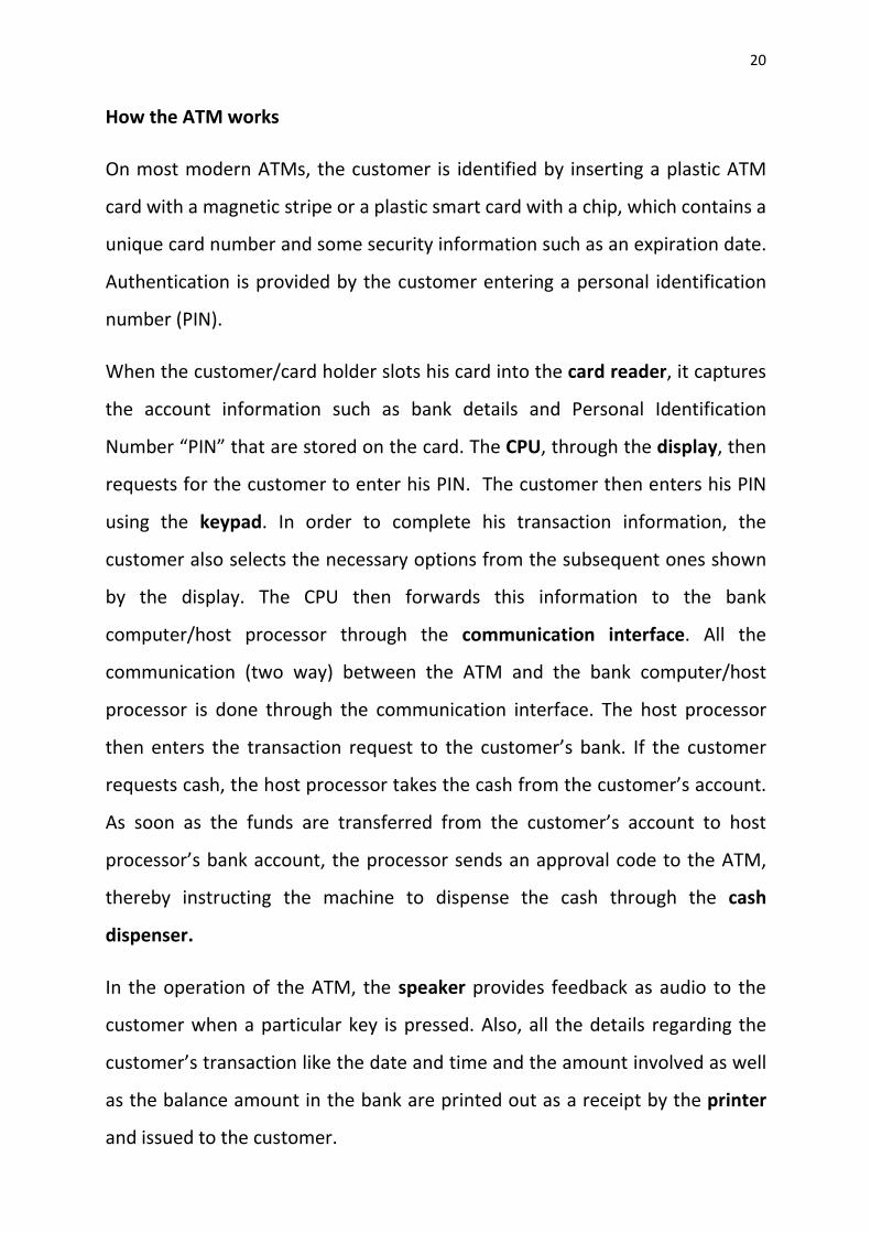
How the ATM works
On most modern ATMs, the customer is identified by inserting a plastic ATM
card with a magnetic stripe or a plastic smart card with a chip, which contains a
unique card number and some security information such as an expiration date.
Authentication is provided by the customer entering a personal identification
number (PIN).
When the customer/card holder slots his card into the card reader, it captures
the account information such as bank details and Personal Identification
Number “PIN” that are stored on the card. The CPU, through the display, then
requests for the customer to enter his PIN. The customer then enters his PIN
using the keypad. In order to complete his transaction information, the
customer also selects the necessary options from the subsequent ones shown
by the display. The CPU then forwards this information to the bank
computer/host processor through the communication interface. All the
communication (two way) between the ATM and the bank computer/host
processor is done through the communication interface. The host processor
then enters the transaction request to the customer’s bank. If the customer
requests cash, the host processor takes the cash from the customer’s account.
As soon as the funds are transferred from the customer’s account to host
processor’s bank account, the processor sends an approval code to the ATM,
thereby instructing the machine to dispense the cash through the cash
dispenser.
In the operation of the ATM, the speaker provides feedback as audio to the
customer when a particular key is pressed. Also, all the details regarding the
customer’s transaction like the date and time and the amount involved as well
as the balance amount in the bank are printed out as a receipt by the printer
and issued to the customer.
Page 21
21
Common ATM Frauds
The evolution of ATMs has resulted in the evolution of ATM Frauds. These
frauds are of various types and employ varying tactics. Amongst these frauds
we have;
Card Skimming: The card details and PIN are captured at the ATM by a device
placed at the card reader and used to produce counterfeit cards for
subsequent fraudulent cash withdrawals. Figure 1.3 shows a typical case of
card skimming.
On the left part of figure 1.3, the skimming device is shown being placed on
top of the card slot/card reader. It looks much like the card reader but it is
fake. The right part of figure 1.3 shows the skimming device fully placed on top
of the card reader. As the card holder slots his card, the skimming device
copies all the information on the card including the PIN and as such copies of
Fig. 1.3: Typical Skimming Device (Source: Google.com).
Genuine Card Slot
Skimming Device
Page 22
22
the card could be made elsewhere and used to withdraw from the same
account. The customer is unaware of the card skimming and sees a normal
transaction and retains the card.
Card Trapping: In this case, the card is physically captured at the ATM by a
device placed at the card slot and the PIN is compromised. Later the card is
retrieved and used to make fraudulent cash withdrawals. The customer loses
the card. Figure 1.4 shows the card trapping device while figure 1.5 shows
how the card trapping device is placed on the card slot.
Fig. 1.4: A typical Card Trapping device (Source: google.com).
Fig. 1.5 Card Trapping Device being placed on genuine card slot (Source:
google.com).
Genuine Card Slot
Card Trapping Device
Page 23
23
Pin Compromise: Here the criminal uses a Pin Pad Overlay to acquire the PIN.
The Pin Pad Overlay is a false PIN pad which is fitted on top of the existing PIN
pad. Most times the Pin Pad Overlay could be a flexible piece of circuit-
embedded plastic that fits perfectly over the ATM's genuine PIN pad. Figure
1.6 shows a pin pad overlay being placed on a genuine keypad.
Sometimes miniature cameras, remotely positioned cameras or video
surveillance could be used to accomplish Pin Compromise.
Fig 1.6: A typical Pin Pad Overlay (Source: google.com).
These frauds necessitate the need for such efforts as Two-Factor
Authentication in other to curb them.
Two-Factor Authentication
This is an authentication mechanism that utilizes a combination of two factors
such as Username and Password, PIN and SMS One Time Password, or
Username and Fingerprint. This method is used by various banks and other
financial institutions for authentication for online banking.
Pin Pad Overlay
Genuine Key Pad
Page 24
24
Most ATMs employ one means of authentication (single factor authentication)
by using the PIN. These kinds of ATMs are vulnerable to ATM frauds like Card
Skimming: where a device placed at the slot for the ATM Card copies all the
information stored in the card including the PIN [3]. Since the PIN is the only
means of authentication (Single Factor Authentication), then the security of
the ATM will be compromised, duplicates of all cards copied will be made and
illegal access to the corresponding bank accounts will be achieved and money
will move to the wrong hands.
This project aims to reduce these ATM frauds by developing the prototype of
the ATM software that will employ a two factor authentication method that
utilises the PIN and a One Time Password (OTP) which will be sent by the ATM,
through SMS, to the client’s mobile phone immediately it accepts his ATM
Card. As this technology is employed, whoever then has access to somebody’s
ATM Card and PIN will fail at any attempt to gain access to their bank account,
unless the fraudulent person has access to the phone (and SMS) which bears
the One Time Password (OTP).
1.2 Statement of the Problem
The need to ensure the security of money while carrying out the automation of
banking services cannot be over-emphasised, i.e. the advantages are
overwhelming. Considering the fact that automation speeds up processes
(most especially the rolling out of services) and the banking sector is at the hub
of economic development, automating retail banking invariably speeds up an
economy and ensures economic growth provided there are means to curb the
resulting frauds.
Page 25
25
1.3 Objectives
The objectives of this project are:
--To develop ATM software that will employ the Two Factor Authentication
process in its operation and thereby achieve the security of funds and the
reduction of ATM frauds.
--This project is aimed at showing that already existing infrastructure for
financial services could be further utilised to enhance the security of financial
transactions and as such save cost of additional hardware needed to achieve
enhanced security.
--To explore the viability of the GSM/SMS technology in enhancing ATM
security.
1.4 Scope of Study
The scope of this work includes the technologies, parameters and processes
that are within this research and they are listed below as follows:
-- Security of ATM transactions and the effect of Two Factor Authentication in
reducing them.
--SMS technology and the Bulk SMS Service: In this work, the SMS technology
is the medium through which the One Time Password is delivered to the
customer.
--Object Oriented Analysis and Design (OOAD): The Software Engineering
involved in this work is firmly rooted in OOAD.
--Unified Modelling Language (UML): The UML is the industry-standard
Modelling language in the field of software engineering. UML is employed in
creating visual models, specifying and constructing software systems and also,
Page 26
26
non-software systems [4]. UML is found to be very useful in carrying out
OOAD.
--Object Oriented Programming (OOP): Usually OOAD gives rise to Object
Oriented Programming. C# is the Object Oriented Programming Language
employed in this research.
1.5 Significance of Study
The significance of this project is that it will provide a viable means of fortifying
the security of money in bank accounts. This project will provide a way of
reducing illegal banking transactions made with the ATM. By employing the
Two Factor Authentication procedure crime will be curtailed and financial
services will be enhanced.
1.6 Proposed Methodology
This work uses the following methodology:
Object Oriented Analysis and Design (OOAD): In this work Object Oriented
Analysis and Design (OOAD) is employed. Using OOAD, Object Oriented
Decomposition is done within the confines of the vocabulary of the problem to
be solved. Object-oriented analysis focuses on the analysis that examines
requirements with respect to the classes and objects found in the description
of the problem domain. By using this methodology requirements will be
organised around objects, which integrate both behaviours (processes) and
states (data) modelled after real world objects that the system interacts with.
Object Oriented Design employs the results obtained through Object-oriented
analysis in order to design the system.
Also, a suitable Software Development Life Cycle (SDLC) is chosen for use in
this work. The choice of the SDLC is the Waterfall Model Software
Page 27
27
Development Life Cycle. At the appropriate stage of this SDLC, OOAD will be
carried out. OOAD also involves the use of graphical modelling and simulation.
Modelling and Simulation: This software system will be modelled using the
Unified Modelling Language (UML). The UML is found very useful in developing
the visual models of a whole lot of systems.
The coding (in C#) and simulation of this system will be done using Visual
Studio.
1.7 Organization of Thesis
The rest of this Thesis is organised as follows;
Chapter Two: Literature Review- In this chapter, an analytical overview of the
significant literature published on this work is provided and their strengths and
weaknesses are exposed. The reasons for this are to gain insight into the work,
to distinguish what has been done from what needs to be done and to
rationalise the significance of the work.
Also the key concepts involved in this work will be looked into and reviewed.
Chapter Three: Research Methodology- This chapter will deal with the
methods involved in carrying out this work. It aims at showing how they are
organised and structured.
Chapter Four: System Analysis and Design- This chapter provides a practical
application of Object Oriented Analysis and Design along with the Waterfall
Software Development Life Cycle in analysing and designing the system in
question.
Chapter Five: System Implementation, Testing and Simulation- Here the
different modules of the software will be implemented. The implementation
Page 28
28
will be done using an object oriented programming language called C#. Also
this chapter will handle the testing and simulation of the software codes.
Chapter Six: Conclusion- Here the work will be summarised and duly
concluded.
Page 29
29
CHAPTER TWO
LITERATURE REVIEW
2.1 Review of the Related Works
In the following, already existing works concerning the improvement of ATM
and Internet Banking security through various technologies are discussed.
(I) Model for Token Based Secure Transaction in ATM Networks by Sonika
Katta, Dinesh Goyal, Ruchi Dave, Naveen Hemrajani, IJCSET, August 2011,
Vol 1, Issue 7, 395-398.
Here, the authors introduce the hardware Token. The hardware Token or
simply Token is a physical device that performs or aids authentication. This can
be a secure storage device containing passwords, such as a bankcard or smart
card. This can also be an active device that yields One-Time Passcodes, either
time-synchronous (changing in synchrony with a master at the host server) or
challenge–response (responding to a one-time challenge). Token security
defences include tamper-resistant packaging and special hardware that
disables the token if it is tampered with or if the number of failed
authentication attempts exceeds a chosen threshold. The token acts like an
electronic key to access something.
In this model if a user wishes to use the ATM, he would use the Token along
with the PIN for authentication and prove that he is who he claims to be
before making any transaction. The token provides the One Time Passcode
needed for authentication [5].
Page 30
30
(II) Authentication in an Internet Banking Environment by the US Federal
Financial Institutions Examination Council (http://www.ffiec.gov/)
In this work, the USB token device is introduced. This device is typically the size
of a house key. It plugs directly into a computer’s USB port and therefore does
not require the installation of any special hardware on the user’s computer.
Once the USB token (the first authenticating factor) is recognized by a
computer in which it is plugged, the customer is prompted to enter his or her
password (the second authenticating factor) in order to gain access to the
computer system and effect financial transactions.
USB tokens are one-piece, injection-moulded devices. USB tokens are hard to
duplicate and are tamper resistant; thus, they are a relatively secure vehicle for
storing sensitive data and credentials. The device has the ability to store digital
certificates that can be used in a public key infrastructure (PKI) environment.
The USB token is generally considered to be user-friendly. Its small size makes
it easy for the user to carry and, as noted above, it plugs into an existing USB
port; thus the need for additional hardware is eliminated [6].
(III) Enhancing ATM security using fingerprint and GSM technology by Ashish
M. Jaiswal and Mahip Bartere, IJCSMC, Vol. 3, Issue. 4, April 2014, pg.28 – 32.
In this design Bankers will collect the customer’s finger prints and mobile
phone number(s) while opening accounts for them, then afterwards the
customer can access the ATM machine. When the customer uses the ATM:
after inserting the card, he must place his finger on the finger print module, he
then gets automatically generated 4-digit code every time as a message to his
mobile phone through GSM modem connected through a microcontroller to
the ATM. The code received by the customer should be entered by pressing
Page 31
31
the keys on the ATM screen, and only after that will he be able to make
transactions [7].
(IV) Facial Verification Technology for Use in ATM Transactions by Aru,
Okereke Eze, Ihekweaba Gozie, AJER, Vol-2, Issue-5, 2013, pp-188-193.
This paper proposes an automatic teller machine security model that would
combine a physical access card, a PIN, and electronic facial recognition. In this
model, as a user walks to the ATM (its digital camera is on 24hours a day), its
computer will automatically initiate a face recognition procedure. Whenever
the computer detects a human face, its camera obtains a picture of the face,
the computer compares the image of the face to the images of those of
registered customers in its database .If the face (as seen by the ATMs camera)
matches the picture of that in the database, then the user is automatically
recognized by the machine [8].
(V) Designing a Biometric Strategy (Fingerprint) Measure for Enhancing ATM
Security in Indian E-Banking System by Sri Shimal Das, Smt. Jhunu Debbarma,
IJICT, Vol. 1, No. 5, September 2011.
In this paper the authors propose the design of an ATM that uses the ATM card
and the customer’s fingerprint (instead of the PIN) in order to achieve
sufficient ATM security. The proposed system works as follows: at the time of
transaction (i.e., after the machine has read and accepted the ATM card),
customers enrol their fingerprint to a high resolution fingerprint scanner. The
fingerprint image is transmitted via secured channel to the central server
which contains a record of customers’ fingerprints. At the banking terminal the
minutiae extraction and matching are performed in order to verify that the
presented fingerprint image belongs to the claimed user in the bank’s
database. Then authentication is granted if the minutiae matching are
Page 32
32
successful, otherwise authentication is denied. This proposed ATM biometric
authentication system consists of five main components. They are: sensor,
feature extractor, fingerprint/template database, and matcher and decision
module. The function of the sensor is to scan the biometric trait of the user.
The function of the feature extraction module is to extract the feature set from
the scanned biometric trait. This feature set is then stored into the template
database. The matcher module takes two inputs, i.e. features set from the
template database and features set of the user who it wants to authenticate
and compares the similarity between the two sets. The last module, i.e., the
verification module makes the decision about the matching of the two features
sets [9]. By doing all these, this proposed system could achieve sufficient
security for ATMs.
Comparison Table for the related works
Title and Author Strength Limitation
Model for Token Based
Secure Transaction in
ATM Networks by Sonika
Katta, Dinesh Goyal,
Ruchi Dave, Naveen
Hemrajani, 2011.
The use of Tokens is
another means of
achieving secure
transactions as against
the use of human
features in biometrics.
It is costly to implement
because of the
introduction of hardware
token.
Page 33
33
Authentication in an
Internet Banking
Environment by the US
Federal Financial
Institutions Examination
Council.
(http://www.ffiec.gov/)
The USB token is a
relatively secure
vehicle for storing
sensitive data and is
generally considered
to be user-friendly
The introduction of the
USB token still adds to
the cost.
Enhancing ATM security
using fingerprint and
GSM technology by
Ashish M. Jaiswal and
Mahip Bartere, 2014.
Fingerprint biometric is
used along with GSM
technology to enhance
security.
The addition of
biometrics introduces
more complexity in terms
of hardware and
software.
Facial Verification
Technology for Use in
ATM Transactions by
Aru, Okereke Eze,
Ihekweaba Gozie, 2013.
In real time
applications, this
approach gives good
results.
Facial Verification is quite
complex.
Designing a Biometric
Strategy (Fingerprint)
Measure for Enhancing
ATM Security in Indian E-
Banking System by Sri
Shimal Das, Smt. Jhunu
Using fingerprint
biometrics ensures a
high level of ATM
security.
The proposed system is
quite complex: it contains
about five intricate
components.
Page 34
34
Debbarma, IJICT, Vol. 1,
No. 5, September 2011.
Advantages of the proposed two factor authentication: Pin and SMS
Password Model over the Above Compared Models
(1) Cost Effectiveness: the proposed model employs already existing ATM,
Internet and GSM infrastructure without needing additional resources in the
form of hardware and software as is the case with designs that involve
biometrics.
(2) Less Complexity: the proposed model achieves lesser complexity because
of no additional hardware or software resources. Complexity is an obvious
disadvantage of the above compared technologies.
2.2 Review of the Technologies involved in the proposed Design
The proposed system involves various technologies that serve unique purposes
in the operation of the system. These technologies are reviewed from section
2.2.1 to section 2.2.4.
2.2.1 Authentication Mechanisms employed in electronic banking
Authentication is the process of verifying a claim made by a subject that
it should be allowed to act on behalf of a given person, computer,
process, etc. Also, Authentication can be defined as the process of
determining whether someone or something is, in fact, who or what it is
declared to be. Authentication works closely with Identification and
Table 2.1: Comparison Table for the related works
Page 35
35
authorization. Identification can be defined as the process of pinpointing
(identifying) someone or something while Authorization can be defined as the
process of giving someone permission to do or have something.
Authentication can be accomplished with, for instance, a password while
Identification can be accomplished with a username, a smart card, or anything
else that can uniquely identify a subject. Once a user is identified and
authenticated, they can be granted authorization based on their proven
identity [10].
It is imperative to understand the difference between authentication,
identification and authorization. Identification occurs when a person claims an
identity (such as with a username) and authentication occurs when a person
proves their identity (such as with a password). Once the person has a proven
identity, authorization techniques can then grant or deny access to services
based on his proven identity [11].
Authorization, involves verifying that an authenticated subject has
permission to perform certain operations or access specific resources.
Authentication procedures are based on three factors related to the user:
i.e. the person who is authenticating, say a transaction in Internet
Banking [12].
They are;
What the user knows: This includes Username, Password, PIN, etc.
What the user possesses: This includes USB token, Smart Card,
SMS/Token, One Time Password (OTP), etc.
What the user is: This refers to features that are peculiar to the user
such as fingerprint, Palm print, IRIS, Retina, Voice, etc.
Page 36
36
There are three kinds of authentication mechanisms, they are;
Single Factor Authentication; this authentication mechanism utilizes only one
of the factors. For example, a Username (User Knows). This is the basic
authentication method [13].
Two Factor Authentication; this authentication mechanism utilizes any two of
the factors. For example, a User using a password as the first factor (User
knows) and a One-Time Password (OTP) as the second factor (User
possesses) to gain access to their account or perform ,for instance, a funds
transfer transaction[13].
Multi Factor Authentication; this authentication mechanism utilizes more than
two of the factors and one of the factors is necessarily a “User is” type. For
example, a large value transaction authorized in a bank by using a combination
of the person’s username, a smart card and his biometric authentication factor
like fingerprint [13].
Multi factor authentication provides users higher levels of protection from
online banking fraud. By employing biometrics (User is) as one factor; Multi
factor authentication improves security for online banking customers and
reduces online fraud. This authentication can be provided for the customers
(corporate or individual customers) who make transactions beyond the
threshold value that was set up by the bank.
Usually, in online Banking a Two Way or Mutual authentication can be
provided between the user and the Organization. It refers to two parties
authenticating each other. When describing online authentication processes,
mutual authentication is referred to as website-to-user authentication. By
means of this authentication, the user knows that they are on the valid
Page 37
37
banking website. Mutual authentication can be implemented by providing
some challenge questions. The customer provides the challenge questions
along with the answers and selects the image (identifiable pictures), image
title and a text phrase (optional) from a collection of images which are
provided in the banking website at the time of enrolment. The customer
can further change this image during his first login. Further when the customer
enters login id and before entering the password, the site asks these
challenge questions and when the user answers them correctly, it displays
the image, title and phrase. A typical example of a challenge question is
“what is your favourite meal?” A typical answer is “Fufu”. If the displayed
image is correct then customer can enter the password and login in. If not
the customer can stop logging in and contact the bank. This makes the
customer to know whether it is a real banking website or fake
website[8]. This facility provides the customer and server the means to
authenticate mutually so that we can reduce Phishing Attacks: this is an
attack aimed at acquiring sensitive information such as usernames, passwords,
or ATM/credit card details by masquerading as a trustworthy person or entity
in an electronic communication[14].
2.2.2 The ATM System Technology
Basically, the ATM is a computer system which grants Bank clients access to
financial transactions from a public space, thereby discarding the need for a
customer to visit any bank’s branch [2]. Figure 2.1 clearly shows a typical ATM
Machine.
Page 38
38
The ATM must be connected to a network in order to achieve its purpose (see
fig. 2.2). With the aid of the ATM, customers would be able make cash
withdrawals, check the balances on their accounts or even pay their bills.
Display Screen
Card Reader
Receipt Printer
Fig. 2.2: Diagram for the ATM Connected to a Network
ATM
ATM
ATM
ACCOUNT
BANK
COMPUTER/HOST -
PROCESSOR
ACCOUNT
ACCOUNT
ACCOUNT
Fig. 2.1: A Typical ATM Machine (Source: circuitstoday.com).
Key Pad
Speaker
Cash Dispenser
Page 39
39
Operation of the ATM Connected to a Network
When a cardholder wants to do an ATM transaction, they provide the
necessary information by slotting their ATM Card into the ATM’s card reader
and when requested, they provide their personal identification number (PIN)
by entering it via the keypad.
The ATM forwards this information to the Bank Computer (also known as host
processor), which routes the transaction request to the cardholder's bank or
the institution that issued the card. If the cardholder is requesting cash, the
host processor causes an electronic funds transfer to take place from the
customer's bank account to the host processor's account.
Once the funds are transferred to the host processor's bank account, the
processor sends an approval code to the ATM authorizing the machine to
dispense the cash [2].
ATMs include many other functions which are not directly related to the
management of one's own bank account, such as the functions below [2]:
• Deposit currency recognition, acceptance, and recycling.
• Paying utility bills, fees, and taxes (utilities, phone bills,
• Printing bank statements.
• Updating passbooks.
• Loading monetary value into stored value cards.
• Purchasing.
• Postage stamps.
• Lottery tickets.
• Train tickets.
• Concert tickets.
• Movie tickets.
Page 40
40
• Shopping mall gift certificates.
• Games and promotional features.
• Donating to charities.
• Cheque Processing Module.
• Adding pre-paid cell phone credit.
An ATM has the following two input devices [2]:
(1) Card reader- The card reader captures the account information stored on
the magnetic stripe on the back of an ATM card. The host processor uses this
information to route the transaction to the cardholder's bank.
(2) keypad/Function buttons - These let the cardholder tell the bank what kind
of transaction is required (cash withdrawal, balance inquiry, etc.) and for what
amount. Also, the bank requires the cardholder's personal identification
number (PIN) for verification.
An ATM has the following four output devices [2]:
(1) Speaker- The speaker provides the cardholder with audio feedback when a
key is pressed.
(2) Display screen- The display screen prompts the cardholder through each
step of the transaction process.
(3) Receipt printer- The receipt printer provides the cardholder with a paper
receipt of the transaction.
(4) Cash dispenser- The heart of an ATM is the safe and cash-dispensing
mechanism. The entire bottom portion of most small ATMs is a safe, because it
contains the cash.
Page 41
41
2.2.2.1 The ATM Hardware
Figure 2.3 shows the block diagram of the ATM and its component devices.
Typically the ATM hardware comprises the following devices [2].
Central Processing Unit (CPU): This is simply a computer system which is used
to control the user interface and all the other devices. Most deployments make
use of the same CPUs found in desktop computers and laptops; CPUs like Intel
Pentium 4, Intel Core i7 and AMD VISION PRO.
Card Reader: The card reader embodies the mechanism that acquires the
account information stored on the chip on the back of an ATM card in order to
identify the customer. The host processor uses this information to route the
transaction to the cardholder's bank.
Encrypting PIN Pad (EPP): This looks much like a calculator keypad. The EPP
contains the security processor, the software function, the encryption keys and
memory to locally perform the PIN-encryption function.
Fig. 2.3: Block diagram for the ATM (Source: Wikipedia.org).
CPU EPP
CARD
READER
CASH CARTRIDGE
CASH CARTRIDGE
CASH CARTRIDGE
CASH CARTRIDGE
HOUSING
VAULT
CASH HANDLING MECHANISM
DISPLAY SCREEN and FUNCTION BUTTONS
Page 42
42
Secure Crypto-Processor: This is a dedicated microprocessor for carrying
out cryptographic (encrypting) operations. It is embedded in a packaging
within a secure enclosure so that it maintains a degree of tamper resistance.
The security of the machine depends heavily on the integrity of the secure
crypto-processor.
Display: This is basically a computer monitor built into the ATM and used by
the customer for performing the transaction.
Function Key Buttons: These buttons are usually located close to the display
and are programmed to perform specific actions like selecting the type of
transaction involved and the amount.
Record Printer: This prints out a record of the customer’s transaction. The
transaction record is normally printed out on a small paper slip.
Vault: This is a secure enclosure that safeguards money and parts of the
machinery that require restricted access. It is intended to protect these from
theft, unauthorized use, fire, natural disasters, and other threats, just like
a safe. Usually, the Vault contains the following Mechanisms: Dispensing
mechanism that provides the cash, Deposit mechanism which allows the
customer to make deposits, Security sensors, Locks that ensure controlled
access to the contents of the vault, Journaling systems like the record printer
or some form of electronic memory that keeps record of transactions, etc [2].
Housing: The housing provides the ATM with the necessary shelter, aesthetics
and physical security.
2.2.2.2 The ATM Software
Standard commercial "off-the-shelf" operating systems and programming
environments can be used inside of ATMs. Typical platforms previously used
Page 43
43
on ATMs include Real time Multitasking Executive (RMX) or Operating
System/2 (OS/2) [1].
Today, most of the ATMs worldwide (over 95%) use Microsoft Windows XP.
Windows XP is a personal computer operating system produced by Microsoft.
The operating system was released to manufacturing on August 24, 2001, and
generally released for retail sale on October 25, 2001.
Windows XP is well known for its security, stability and efficiency due to its use
of Windows NT Kernel. Unlike its predecessors such as Windows 2000 and
Windows ME, it introduced a significantly redesigned graphical user
interface and was the first version of Windows to use product activation in an
effort to reduce software piracy.
Windows XP offers Internet features such as Internet Explorer 6, Outlook
Express 6, Windows Messenger and MSN Explorer. New networking features
were also added to XP, including Internet Connection Firewall, Internet
Connection Sharing, Quality of Services features, Internet Protocol version 6
(IPv6), network bridging, peer to peer networking, support for most DSL
modems, IEEE 802.11 (Wi-Fi) connections with auto configuration. Remote
Assistance and Remote Desktop were also added; these two allow users to
connect to a computer running Windows XP from across a network or the
internet and access their applications, files, printers and devices [15]. Table 2.2
below shows the Windows XP System Requirements.
Central Processing Unit (CPU) X86 (Intel Pentium) or compatible
CPUs (e.g. AMD Athlon).
Memory 256 MB.
Hard Drive 1.5 GB.
Page 44
44
Media CD-ROM drive or compatible ones.
Display Super Visual Graphics Adaptor (VGA).
Sound Hardware Sound Card, Speakers and head
phones.
Input Devices Keyboard, mouse, etc.
ATM Vendors and financial institutions have a wide range of Application
Programs to drive their machines. These programs run on the aforementioned
Operating System. The Application Programs are developed using any of these:
Extensions for Financial Services (XFS), Java Extensions for Financial Services
(J/XFS) and XPEAK [1].
(1) Extensions for Financial Services (XFS)
The XFS standard was initiated by Microsoft in the early 90's and it was called
WOSA/XFS. The acronym stands for Windows Open Services
Architecture/Extension for Financial Services. As it became an international
standard adopted by the European Committee for Standardization (CEN), it
then became known as CEN/XFS. The CEN/XFS standard defines a common
language to speak with the hardware components of the Automated Teller
Machine (ATM).
The architecture of CEN/XFS is similar to a client-server model, where the
server knows how to drive a particular ATM hardware component. The server
must publish a standard interface which is common for all similar hardware
components. The client application programm benefits from the services
Table 2.2 Windows XP System Requirements (Source: http://en.wikipedia.org/
wiki/Microsoft_windows_xp).
Page 45
45
provided by the server (also called Service Provider or SP) and uses its
standardized interface to drive hardware components from different
manufacturers with the same set of commands.
This is a huge benefit, because it virtually unifies different ATM platforms, and
creates a common environment for the ATM applications all over the world
[16].
CEN/XFS shares a common conceptual background with Microsoft Windows
device drivers. This common conceptual background with Microsoft Windows
device drivers is hinged on forward compatibility. For instance, Windows
drivers are designed to be forward-compatible such that a Windows driver can
run on a version of Windows newer than what the driver was initially written
for, but doing that would mean that the driver cannot take advantage of any
new features introduced with the new version [17]. In the same way CEN/XFS
ensures that client applications can run on a version of the server that is newer
than what the application was initially written for.
Also Windows drivers are generally not backward-compatible: a Windows
driver is not guaranteed to run on any older version of Windows. For example,
a driver written for Windows 2000 can work on Windows XP (which is higher)
but will not make use of any of the new features that were introduced in
Windows XP. However, a driver written for Windows XP may or may not load
on Windows 2000. In the same manner CEN/XFS allows that client applications
may not run on a version of the server that is older than what the application
was initially written for.
(2) XPEAK
Xpeak aims to become the standard for devices management, not only in the
financial arena, but also for all market types. It is a question of creating a
Page 46
46
standard which is independent of the operating system and the programming
language, as well as of the communications interface (Sockets, Web Services,
USB, etc.) which is used to send messages in XML (Extensible Markup
Language) format.
Xpeak is not an acronym and the name itself is indicative of its main objective:
to communicate with devices (speak) using Xml. It aims to homogenise the
messaging between an application and a device; to communicate
independently of the language used by the application. In fact, it is possible
that it could achieve an architecture in which, to give one example, an
application could be developed in Java and use Xpeak Services from different
suppliers, some implemented in Java, others in C++ and still others in the
device's firmware [18].
For further illustration, the example in fig. 2.4 shows the Xpeak architecture.
The figure shows the ATM application program that communicates (speaks)
with a peripheral device such as the Encrypting Pin Pad (EPP) or Record Printer
using XML Commands like XPEAK_COMMAND_READ (which enables the ATM
to read from the EPP) or XPEAK_COMMAND_PRINT (which enables the ATM
to print from the printer). The ATM application program could be written in
any of the popular programming languages like C++, C#, Java, etc. It does not
matter who the manufacturer of the ATM or the peripheral device is. It also
does not matter the language used to write the ATM application program or
the Xpeak services/drivers that come with the peripheral devices. All that
matters is that the ATM application program sends the XML commands to the
peripheral devices of the ATM [18].
Page 47
47
Fig. 2.4: Xpeak architecture
(3) Java Extensions for Financial Services (J/XFS)
Recognising the advantages of the Java language for developing finance
industry applications, representatives of Diebold, IBM, NCR, Talaris, Wincor
Nixdorf International GmbH and Sun Microsystems, embarked on an effort to
develop a set of standard Java interfaces in support of the unique input and
output peripheral devices used in the finance industry at various access
channels including Branch Teller and Platform, Self-Service and Call Centre.
This new standard is called J/XFSTM (Java eXtensions for Financial Services) for
the JavaTM platform. This initiative has produced a finance industry standard
for financial I/O devices that supports 100% pure Java applications while
leveraging existing standards [19].
Utilizing the Java language, J/XFS provides a standard for a banking device
subsystem with real platform and hardware independence which enables the
access to banking peripherals for new Java banking applications. It also
provides a migration path for current financial I/O subsystems and ensures co-
existence between current Client/Server and new Java banking applications, so
customer investments in banking device infrastructure are protected.
ATM application program
ATM’s peripheral devices
XML
Page 48
48
J/XFS enables full transparency between the application and the device level
[19].
Peripheral Devices supported by the CEN/XFS, J/XFS, XPEAK specifications
The following devices are supported by the CEN/XFS, J/XFS, XPEAK
specifications:
Printers and Scanners
Identification Card Units
Cash Dispensers
Personal Identification Number Keypads
Check Readers and Scanners
Depository Units
Text Terminal Units
Sensors and Indicators Units
Cameras
Alarms
Card Embossing Units
Cash-In Modules
Card Dispensers
Barcode Readers
Item Processing Modules
Page 49
49
2.2.3 Short Message Service (SMS)
Figure 2.5 shows the main components of SMS network architecture.
Fig. 2.5: SMS network architecture
When routing a mobile originated short message service, the Short Message
Service Center (SMSC) forwards the short message to the Short Message
Service Gateway Mobile Services Switching Center (SMS-GMSC). The SMS-
GMSC interrogates the Home Location Register (HLR) for routing information
when the Handset is in the HLR’s geographical area of coverage but when it is
not, the Visitor Location Register (VLR) that covers the geographical area in
question is interrogated for routing information. The SMS-GMSC then sends
the short message to the appropriate Mobile Services Switching Center (MSC).
The MSC delivers the short message to the Handset, otherwise known as the
Mobile Station (MS). On the other hand, when routing a mobile terminated
short message, the MS addresses the required SMSC according to its global
title. If roaming abroad the visited public limited mobile network (PLMN) will
route the short message to the appropriate Short Message Service
Interworking Mobile Services Switching Center (SMS-IWMSC) [20].
The SMSC identifies each short message uniquely by adding a time stamp in
the SMS-DELIVER TP-SCTS field (TP-SCTS: Transfer Protocol Service Center Time
SMSC SMS-GMSC/
SMS-IWMSN MSC MS
HLR VLR
Page 50
50
Stamp). The short message arrival at the SMSC is accurate to the second. It is
the SMSC’s responsibility to assure that if two or more short messages arrive
within the same second their time stamps will be different.
The MS has to be able to receive/submit a short message Transfer Protocol
Data Unit (TPDU), and then return a Delivery report upon successful reception.
It is also responsible for notifying the network when it has memory capacity
available to receive one or more messages, if it had previously rejected a short
message because its memory capacity was exceeded [20].
2.2.3.1 Bulk SMS Service
Sending instant discrete messages is undertaken by SMS while the medium
of Bulk SMS enables an organization or institution to reach the masses with
the same notification at the same time.
There are many advantages of this technology but the most eminent one is its
time saving feature that makes it so much preferred. One can send thousands
of SMS to many people in just a few minutes.
A lot of software that allows the use of Bulk SMS directly from the personal
computer is available on the internet. Also there are numerous bulk SMS web
sites that provide the SMS Gateway for bulk SMS and also provide all the
related services necessary for any type and size of organization. The Bulk SMS
solutions include user-friendly software that makes the task of sending
messages in bulk quite easy [21].
The Bulk SMS Service relies heavily on the SMS GATEWAY. The SMS Gateway is
a service which allows a computer to send or receive SMS to or from a
telecommunications network [22]. Bulk SMS web sites (service providers)
provide the SMS Gateway. For someone to utilise the SMS Gateway, they have
Page 51
51
to open an account with the Bulk SMS Service Provider on their website for a
fee. The SMS Gateway used in this work is provided by “eTextmail”. This
service provider is based in Lagos, Nigeria. Their website is
http://www.etextmail.com.
2.2.4 Mechanism employed in this work for sending the One Time Password
The mechanism that sends the One Time Password comprises the proposed
ATM software, an SMS gateway and SMS Network (GSM) as shown in figure
2.6.
Fig. 2.6: Mechanism for sending the One Time Password
During authentication, the ATM software sends the OTP and the destination
phone number, through the internet, to the SMS Gateway. The SMS Gateway
then sends the OTP and the destination phone number, through the internet,
to the SMS Network. Afterwards, the SMS Network sends the OTP to the
destination phone number, through the Global System for Mobile
Communication (GSM).
The destination phone number is the customer’s phone number, which in this
case is the number of the author of this thesis.
SMS
GATEWAY
SMS NETWORK
(GSM) MOBILE
PHONE
ATM
SOFTWARE
(OTP)
Page 52
52
CHAPTER THREE
RESEARCH METHODOLOGY
3.1 Methods Adopted for this Work
The methodology for this work is Object Oriented Analysis and Design (OOAD)
along with Modelling and Simulation using Unified Modelling Language (UML)
and C# respectively. This chapter elaborately discusses the elements of OOAD
and UML. Here the key elements of OOAD are exposed and illustrated using
the ATM.
3.1.1 Object Oriented Analysis and Design (OOAD)
Object-oriented analysis is a Software Engineering method which focuses on
the analysis that examines requirements with respect to the classes and
objects found in the description of the problem domain. Object-oriented
design refers to the method of Software design which includes the process of
object-oriented decomposition and a notation for portraying the logical and
physical, as well as static and dynamic models of the system being designed. In
object oriented decomposition we identify objects from the vocabulary of
the problem domain and view them as a collection of independent
agents that collaborate to exhibit a certain higher level behaviour [23].
Normally in the design of software systems, using the object oriented
approach, the two methods above are combined; hence we have Object
Oriented Analysis and Design (OOAD). Basically, it is the products of
object oriented analysis that serve as the models from which an object-
oriented design is started; the products of object-oriented design can then be
made use of as blueprints for the complete realisation of a system using
object-oriented programming methods.
Page 53
53
OOAD places data and the operations that are related to them within a single
entity called an object; this approach has eliminated many of the
problems that are associated with the procedural approach to software
development. In OOAD everything is an object and every object has
attributes and actions associated with it. Therefore each object in OOAD
models a certain object in the real world. This approach organizes programs
in a way that so-closely resembles the real world, in which all objects
are associated with both attributes and behaviour. With the use of OOAD
software reusability is very much improved and the development,
improvement and maintenance of software become remarkably easier than it
used to be under the procedural approach [23].
In Object-Oriented Analysis and Design, the following Terms are frequently
employed: Object, Class, Encapsulation, Inheritance, and Polymorphism.
I. Object: In real life, an Object is a visible and tangible thing or entity [24].
For instance, a chair is an object. Likewise a living creature like a dog is
an object. Objects have two characteristics: they
have state and behaviour. For instance, a car has states such as “current
gear, current speed” and it has behaviour such as “changing gear,
applying brakes”.
The ATM has states such as “ATM not servicing a customer, asking for
entry of PIN, displaying menu of transaction types, asking whether
customer wants to perform another transaction” and it has behaviour
such as “ATM system ejects card, system ejects cash, system displays an
error screen”. Identifying the state and behaviour for real-world objects
is a good way to start in carrying out Object Oriented Analysis and
Design.
Page 54
54
II. Class: A class is a family of related objects. In other words an object is
the instance of a class. A class is the template used to create uniform
individual objects [24]. For example, there are different types of cars:
Saloon, Wagon, etc. Though these cars have different qualities and
features, they still belong to that one family of machines called cars. This
family is the class. Thus we can have a Car Class. A class is the blueprint
from which individual objects are created whereas the individual objects
are simply the instances of the class.
In the ATM, there could be many classes such as Account Information,
Banking Class, Transaction Class, ATM Class, etc. Each of these classes is
a family of related instances of the class (objects) along with
properties/attributes and behaviour/methods. For instance, the Account
Information Class could have such objects as, account type, time of last
transaction, minimum balance, date of account opening, along with
methods such as checkbalance(), checkdate() and properties such as
currency, transaction history, etc (see figure 3.1).
Fig. 3.1:
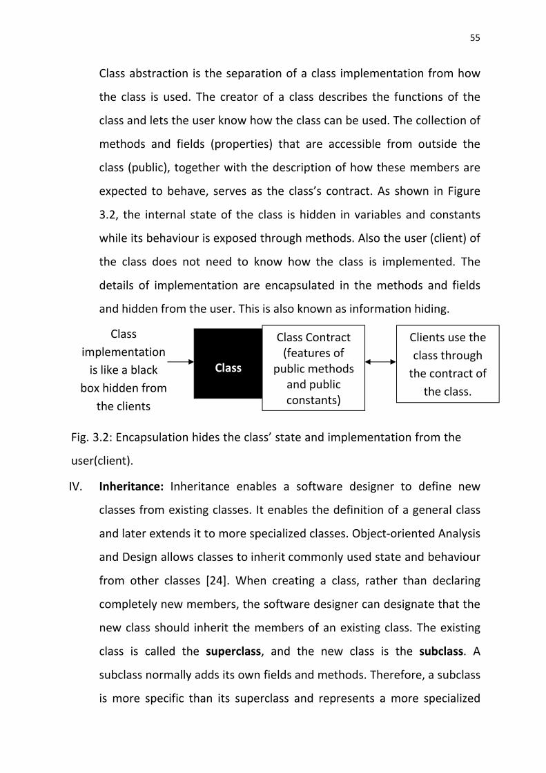
III. Encapsulation: This is an Object Oriented Concept that allows Objects of
a class to hide their internal states in fields or variables but expose their
behaviour through methods or functions [24]. It is also known as class
encapsulation. Class encapsulation is interwoven with class abstraction.
Class Name
Properties (Attributes)
Methods (Behaviour)
Account Information
Currency Transaction History
checkdate() checkbalance()
Fig. 3.1: Typical diagram of a class
Page 55
55
Class abstraction is the separation of a class implementation from how
the class is used. The creator of a class describes the functions of the
class and lets the user know how the class can be used. The collection of
methods and fields (properties) that are accessible from outside the
class (public), together with the description of how these members are
expected to behave, serves as the class’s contract. As shown in Figure
3.2, the internal state of the class is hidden in variables and constants
while its behaviour is exposed through methods. Also the user (client) of
the class does not need to know how the class is implemented. The
details of implementation are encapsulated in the methods and fields
and hidden from the user. This is also known as information hiding.
IV. Inheritance: Inheritance enables a software designer to define new
classes from existing classes. It enables the definition of a general class
and later extends it to more specialized classes. Object-oriented Analysis
and Design allows classes to inherit commonly used state and behaviour
from other classes [24]. When creating a class, rather than declaring
completely new members, the software designer can designate that the
new class should inherit the members of an existing class. The existing
class is called the superclass, and the new class is the subclass. A
subclass normally adds its own fields and methods. Therefore, a subclass
is more specific than its superclass and represents a more specialized
Fig. 3.2: Encapsulation hides the class’ state and implementation from the
user(client).
Class
implementation
is like a black
box hidden from
the clients
Class
Class Contract (features of
public methods and public constants)
Clients use the
class through
the contract of
the class.
Page 56
56
group of objects. Typically, the subclass exhibits the behaviours of its
superclass and additional behaviours that are specific to the subclass.
The ATM software could have such classes as “Withdrawal Class, Deposit
Class and transfer class”. These classes have some qualities in common
with each other. One common quality amongst them is that each one of
them is a type of transaction. In this case they would be subclasses that
inherit the features of a superclass that contains the qualities that they
have in common (see figure 3.3). Such a superclass could be named
“Transaction Class”. An arrow headed line points to the superclass.
V. Polymorphism: Polymorphism enables the development of software
that process objects that share the same superclass in a class hierarchy
as if they are all objects of the superclass. It is the provision of a single
interface (method) to entities (objects) of different types [24]. With
polymorphism, the same method name and signature can be used to
cause different actions to occur, depending on the type of object on
which the method is invoked. Polymorphism means “many forms”.
Fig 3.3: Withdrawal class, Deposit class and Transfer class inherit from
Transaction class as shown with a small triangle pointing to the superclass.
Deposit Class
Shared Properties
Shared Methods
Withdrawal Class
Shared Properties
Shared Methods
Transfer Class
Shared Properties
Shared Methods
Transaction Class
Shared Properties
Shared Methods
Page 57
57
Consider the following example of polymorphism. In the illustration in
figure 3.3, “withdrawal class, deposit class and transfer class” are
subclasses of the superclass “transaction class”. Transaction class
contains a method “execute” which carries out a transaction. Each
subclass implements the “execute” method. When the program sends
the same message (execute) to objects of these classes, each class will
respond to the “execute” message in a unique way: withdrawal will
release money to a customer, deposit will accept money from a
customer while transfer will send money to a different account
somewhere else. Relying on each object to know how to "do the right
thing" (i.e., do what is appropriate for that type of object) in response to
the same method call is the key concept of polymorphism. The same
message (in this case, execute) sent to a variety of objects has "many
forms" of results, hence the term polymorphism.
In this chosen methodology, Software Engineering principles are employed in
analysing and designing the system in question. Basically, this involves the use
of Object Oriented Analysis and Design (OOAD) along with a suitable Software
Development Life Cycle (SDLC). The Waterfall Model is the Software
Development Life Cycle of choice in this work.
In applying the Waterfall Life Cycle to this design, Object Oriented Analysis and
Design (OOAD) is employed at the appropriate stages of the Life Cycle.
3.1.1.1 The Waterfall Model Software Development Life Cycle
Software in its nature is intangible, time consuming and requires a lot of
resources. Because of this nature of software, a haphazard approach towards
the development of software has to be avoided and a disciplined process
adopted. This process otherwise known as Software Development Life Cycle
Page 58
58
(SDLC) is a collection of defined activities, actions and tasks that are performed
when software is to be created.
The Waterfall Model is the “SDLC” of choice in this project. Waterfall approach
was the first Process Model to be introduced and followed widely in Software
Engineering. In this project the Waterfall Model is preferred for the following
reasons;
Easy to understand: The stages and activities of the waterfall model are
well defined and therefore easy to comprehend·
It is widely used and known such that resources on it are readily and
easily available.
Being a linear model and progressing sequentially from one stage to the
next, it is very simple to implement.
It’s a good model to start with for someone with limited software design
experience.
Phases are processed and completed one at a time and not overlapped
with one another.
The amount of resources required to implement this model is minimal.
It ensures that all requirements and features are defined before design
and coding.
Generally, this model leads to a project being delivered on time because
each phase has already been planned in detail.
In "The Waterfall" approach, the whole process of software development is
divided into separate process phases.
The phases in Waterfall model are: Requirements Definition phase, Software
Design, Implementation, Integration and Testing, Operation and Maintenance.
All these phases are cascaded to each other so that second phase is started as
Page 59
59
and when defined set of goals are achieved for first phase and it is signed off,
so the name "Waterfall Model" [24]. All the methods and processes
undertaken in Waterfall Model are more visible. Figure 3.1 clearly shows the
Waterfall model and its stages. In this figure each later stage has a bold arrow
headed dashed line that points upwards to the immediate earlier stage and
that is called interstage feedback. The interstage feedback implies that a stage
preceding an ongoing stage could be revisited for any necessary revision. The
interstage feedback is a modification on the original waterfall model which has
no feedback.
Operation and
Maintenance
Integration and
System Testing
Implementation
and Unit Testing
System and
Software Design
Requirements
Analysis and
Definition
Fig. 3.4: The Waterfall Model (with interstage feedback)
Page 60
60
The stages of "The Waterfall Model" are:
Requirements Analysis & Definition: All possible requirements of the system
to be developed are captured in this phase. Requirements are set of
functionalities and constraints that the end-user (who will be using the system)
expects from the system. The requirements are gathered from the end-user by
consultation, these requirements are analysed for their validity and the
possibility of incorporating the requirements in the system to be developed is
also studied. Finally, a Requirement Specification document is created which
serves the purpose of guideline for the next phase of the model.
System & Software Design: At this stage Object Oriented Analysis and Design
(OOAD) is done. Before starting the actual coding, it is highly important to
understand what we are going to create and what it should look like. The
requirement specifications from first phase are studied in this phase and
system design is prepared. System Design helps in specifying Hardware and
Software systems requirements and also helps in defining overall system
architecture. The system design specifications serve as input for the next phase
of the model.
Implementation & Unit Testing: On receiving system design documents, the
work is divided in modules/units and the actual coding is started. At this stage
Object Oriented Programming (OOP) is done. The system is first developed in
small programs called units, which are integrated in the next phase. Each unit
is developed and tested for its functionality; this is referred to as Unit Testing.
Unit testing mainly verifies if the modules/units meet their specifications.
Integration & System Testing: As specified above, the system is first divided in
units which are developed and tested for their functionalities. These units are
Page 61
61
integrated into a complete system during Integration phase and tested to
check if all modules/units work well with each other and if the system as a
whole behaves as per the specifications. After successfully testing the
software, it is delivered to the customer.
Operations & Maintenance: This phase of "The Waterfall Model" is virtually a
never ending phase (Very long). Generally, problems with the system
developed (which are not found during the development life cycle) come up
during operations, so the issues related to the system are solved after
deployment of the system. Not all the problems appear initially but they arise
from time to time and need to be solved; hence this process is referred as
Maintenance.
Advantages and Disadvantages of Waterfall Model
Advantages
The advantage of waterfall development is that it allows for
departmentalization and managerial control. A schedule can be set with
deadlines for each stage of development and a product can proceed through
the development process like a car in a carwash, and theoretically, be
delivered on time. Development moves from concept, through design,
implementation, testing, installation, troubleshooting, and ends up at
operation and maintenance. Each phase of development proceeds in strict
order, without any overlapping or iterative steps.
Disadvantages
The disadvantage of waterfall development (without feedback) is that it
does not allow for much reflection or revision. Once an application is in the
testing stage, it is very difficult to go back and change something that was not
well-thought out in the Concept/Requirements Analysis and Definition stage.
Page 62
62
3.1.2 Modelling and Simulation
This software system employs the Unified Modelling Language (UML). The
UML is found very useful in developing the visual models of a whole lot of
systems.
UML is the industry-standard language for specifying, visualizing, constructing,
and documenting the artefacts of software systems, as well as other non-
software systems [4]. UML simplifies the complex process of software design,
making a "blueprint" for construction, and is now the standard notation for
software architecture.
The following UML diagrams are used in this work:
Use Case Diagram: This shows a set of use cases and actors (a special kind of
class) and their relationships. A use case is a set of functionalities provided by
an entity (system) as a service to actors. A use case shows the features of a
system [4]. Use case diagrams address the static use case view of a system,
these diagrams are important in organizing and modelling the behaviours of a
system. Figure 3.5 shows a typical Use Case Diagram, the diagram shows how
an actor (user) interacts with the system by accessing the various
functionalities. In the Use Case diagram, the use cases are displayed as ovals.
The actor is connected by lines to the use cases that he carries out. The Use
Case Diagram for the proposed system is shown in chapter 4, figure 4.3
Page 63
63
Fig. 3.5: A typical Use Case Diagram
Class Diagram: This shows a set of classes and their relationships [4]. Class
diagrams are the most common diagrams used in modelling object-oriented
systems. The classes represent the things that are handled in the system.
Classes can be related to each other in a number of ways: they can be
associated (connected to each other), dependent (one class depends on or
uses another class), etc. All these relationships are shown in a class diagram
along with the internal structure of the classes in terms of attributes
(properties) and operations (methods). Figure 3.6 shows a typical Class
Diagram. In the diagram, class1 is in an association relationship with class2;
where N objects of class1 are associated with N objects of class2 as shown by
the Ns at the end of the horizontal line linking the two classes. An association
relationship basically means that objects of one class are simply connected to
objects of the other class. Class3 is in an inheritance relationship with class2 as
shown by the arrow headed line pointing up from class3 to class2. The Class
Diagram for the proposed system is shown in chapter 4, figure 4.4.
Functionality1
Functionality2
Functionality3 Actor
System
Page 64
64
Fig. 3.6: A typical Class Diagram
Sequence Diagram and Collaboration Diagram: These are interaction
diagrams. Interaction diagrams address the dynamic view of a system.
Sequence diagram emphasizes the time ordering of messages between objects
in the system, while collaboration diagram emphasizes the structural
organization of the objects that send and receive messages [4]. Sequence
diagrams and collaboration diagrams are isomorphic, and can be transformed
from one into the other. Since either of them contributes to the same extent in
the understanding of our system and the sequence diagrams give more ideas
of time, which is essential for real time systems, then only the Sequence
Diagram is given and used in this work. The Sequence Diagram for the
proposed system is shown in chapter 4, figure 4.1.
Sequence diagrams describe interactions among objects by depicting the time
ordering of their communication, i.e. method invocations. The typical
sequence diagram shown in figure 3.7 consists of the following elements:
N N
Class 1
Properties
Methods
Class 3
Class 2
Properties
Properties
Methods
Methods
Page 65
65
Class role represents the role an object plays. The objects at the top of
the diagram represent class roles.
Lifeline represents the existence of an object over a period of time. A
vertical dashed line extending from the object is used to denote a
lifeline.
Activation represents the time during which an object is performing an
operation. Thin rectangles placed on lifelines are used to denote
activations.
Method invocation represents communications between objects.
Horizontal arrows labelled with method calls are used to denote method
invocations.
Class Role Object1 Object2
Activation
Method1
Method2
Method Invocation
Method Invocation
Fig. 3.7: A typical Sequence Diagram
Page 66
66
Activity Diagram: This a special kind of State chart diagram showing the flow
from activity to activity within the system [4]. Figure 3.8 shows a typical
Activity Diagram. The activity diagram shows a sequential flow of actions. It
depicts the dynamic behaviour of a system or part of a system through the
flow of control between actions that the system performs. It consists of
actions, which are the basic unit of behaviour that make up an activity. It is
similar to a flowchart except that an activity diagram can show concurrent
flows.
The activity diagram has a number of features such as control nodes for
showing control flows. Control nodes are used to guide the flow of control
through a group of activities and actions. Control nodes are in a variety of
forms. The control nodes are as follows [see figure 3.8];
Initial Node: A sequence of activities or actions is started with an initial node.
An initial node is shown as a large dot.
Final Activity Node: The final-activity node is used to end all control flows and
object flows in an activity. It is shown as a white circle with a large dot inside.
Action Node: The action node represents a simple piece of behaviour. The
action node is shown as a rectangle that is rounded at the edges. The name of
the behaviour is placed as text inside the rounded rectangle.
Control Flow Line: This is the arrow headed line that connects actions and
activities together. It shows the sequence of execution.
Decision Node: A decision node uses a test to make sure that an object or
control flow goes down only one path. This node is used when there is need to
construct an if-then-else selection for an execution path. A decision node is
indicated with a large diamond shape. A control-flow arrow is drawn to
Page 67
67
connect the diamond with each downstream activity or action. The decision
criteria for each path is placed in square brackets on the control flow line.
Fork/Join: Sometimes it is necessary for actions to work in parallel. To split
behaviour into concurrent operations, the fork node is used. A fork node looks
like a fork. A fork node is depicted with one line going into the fork and
multiple lines coming out from the other side. A join node is the opposite of a
fork node. It is used to bring parallel flows of operations back together. Its
symbol looks like the mirror image of a fork.
The Activity Diagram for the proposed system is shown in chapter 4, figure 4.2
[Decision Criterion1]
[Decision
Criterion2]
Fig. 3.8: A typical Activity Diagram
State 1
State 2
Initial Node
Join Node
Control Flow Line
Decision Node
Action Node
Final Node
Page 68
68
Deployment Diagram: This shows the configuration of run-time processing
nodes (Hardware) [4]. Deployment diagrams show the physical architecture of
a system. It is essentially a connected arrangement of hardware. The hardware
nodes are represented as three-dimensional boxes. Any type of hardware that
can execute software and talk to other hardware devices—for example,
printers, modems, scanners, and external disk drives—are represented as
nodes on a deployment diagram.
Lines are drawn between nodes to represent communication paths between
the hardware components. The communication paths represent such things as
local area networks, GSM Network, Radio Frequency (RF) Network, the
Internet, a USB cable, or any mechanism that links one node to another. Figure
3.9 shows a typical Deployment Diagram. The Deployment Diagram for the
proposed system is shown in chapter 4, figure 4.5.
Hardware1
Hardware3 Hardware4
Hardware2
Fig. 3.9: A typical Deployment Diagram
Page 69
69
The aforementioned diagrams capture different information about any
particular software system. Each diagram constitutes a separate visual model
of a system. By assembling these models into one document, a clear and fully
descriptive visual model of a system is obtained and that is the UML model of
the system. The UML modelling for the proposed system is shown in chapter 4,
section 4.1.1.
The coding of this system employs C# (C Sharp) Programing Language and the
necessary simulation employs the popular Software Development tool called
Microsoft Visual Studio 2010.
Page 70
70
CHAPTER FOUR
SYSTEM ANALYSIS AND DESIGN
4.1 System Specification
4.1.1 Requirements Definition
The requirements definition outlines how the ATM performs its functions. The
mode of operation of this ATM system consists of authenticating the user
based on his/her account number, PIN and OTP. This is followed by the
execution of financial transactions. To authenticate a user and perform
transactions, the ATM must interact with the database of the bank account.
For each bank account, the database stores an account number, a PIN and a
balance indicating the amount of money in the account. Upon first
approaching the ATM, the user should pass through the following steps:
Step 1: The screen displays “Welcome to our bank” and prompts the user to
slot in his/her ATM card.
Step 2: The user slot in his/her ATM card.
Step 3: The screen prompts the user to enter the PIN associated with the
specified account number.
Step 4: The user enters the PIN using the keypad. If the PIN is correct he/she
proceeds to step 5 but if not correct, he/she will repeat step 4.
Step 5: The screen prompts the user to enter the OTP.
Step 6: The user enters the OTP using the keypad. If the OTP is correct he/she
proceeds to step 6 but if not correct, he/she will repeat step 5.
Step 7: If the user enters a valid account number, the correct PIN for that
account and the correct OTP for the transaction, the screen displays the
Transaction menu (Fig. 5.2).
Page 71
71
After the ATM authenticates the user, the Transaction menu contains options
such as balance inquiry, withdrawal, etc. The user will then choose the
appropriate option.
If the user chooses to make a balance inquiry, the screen displays the user’s
account balance. To do so, the ATM must retrieve the balance from the bank
account database. The following steps describe what occurs when the user
chooses to make a withdrawal:
Step 1: The screen displays a menu (Fig. 5.11) containing various types of
accounts for the user to select from.
Step 2: The screen displays a menu (Fig. 5.12) containing standard withdrawal
amounts. The menu also contains an option to allow the user to enter their
preferred withdrawal amount.
Step 3: The user chooses an amount to withdraw.
Step 4: If the withdrawal amount chosen is greater than the user’s account
balance, the screen displays a message stating this and telling the user to
choose a smaller amount. The ATM then returns to Step 2. If the withdrawal
amount chosen is less than or equal to the user’s account balance (i.e., an
acceptable amount), the ATM proceeds to Step 5. If the user chooses to cancel
the transaction, the ATM displays the Transaction menu and waits for user
input.
Step 5: The ATM debits the withdrawal amount from the user’s account in the
bank’s database (i.e., subtracts the withdrawal amount from the user’s
account balance).
Step 6: The cash dispenser dispenses the desired amount of money to the
user.
Step 7: The screen displays a message reminding the user to take the money.
Page 72
72
4.1.2 UML Modelling of the System
The proposed system was modelled using the Unified Modelling Language
(UML). In chapter 3 it was discussed that the Unified Modelling Language is a
graphical language for visualizing, specifying, constructing and documenting
the artefacts of a software-intensive system. The UML offers a standard way to
write a system’s blueprints, such as its functions and components.
Modelling the system using UML involves the following:
Capturing the system’s communication using Sequence Diagram.
Specifying the system’s workflow using Activity Diagram.
Specifying the system’s features using Use Case Diagram.
Providing the structural view of the system using Class Diagram.
Specifying the system’s Hardware components using Deployment
Diagram.
The above mentioned actions capture different information about any
software system in particular. Each of the diagrams provides a distinctive visual
model of the system.
The following are the Sequence Diagram, Activity Diagram, Use Case Diagram,
Class Diagram and Deployment Diagram that make up the UML model of the
system.
Page 73
73
SMS Gateway
Customer
Fig. 4.1: Sequence diagram of the system
ATM accepts the SMS
Password (OTP) and
grants him access to
his account.
Customer enters the SMS
Password.
ATM welcomes the
customer and requests
his PIN.
Customer enters his PIN.
SMS Gateway sends
One Time Password
(OTP) to GSM Phone
held by the customer.
ATM accepts the PIN
and requests for SMS
Password (OTP).
ATM sends One
Time Password
(OTP) to SMS
Gateway.
Customer slots his card.
GSM Phone ATM
System Sequence diagram
Page 74
74
As discussed in chapter 3, the UML Sequence diagram shows the dynamic
communications between objects during the execution of a task. It presents
the order in which messages are sent between the objects to accomplish that
task. It also shows an interaction between objects as something that happens
at one specific point in the execution of the system.
Figure 4.1 shows the Sequence diagram for the proposed system. It shows the
Customer, ATM, SMS Gateway and GSM Phone as the entities that
communicate with each other. The communication is shown as arrow headed
lines that start from one object’s lifeline and terminate at the other’s lifeline.
The Sequence diagram of this system implies that after the customer slots his
card, the ATM sends a One Time Password (OTP) to the SMS Gateway and
afterwards the SMS Gateway sends the One Time Password to the GSM Phone
held by the customer. Then the ATM welcomes the customer and requests his
PIN. The customer enters his PIN and afterwards ATM accepts the PIN and
requests for SMS Password (OTP). The customer enters the SMS Password.
Then the ATM accepts the SMS Password and grants him access to his account.
Page 75
75
[NO]
[YES]
[Genuine PIN]
[Genuine OTP]
Perform Transaction
Insert Card
Would you Perform another Transaction?
[Ingenuine PIN (Maximum number of trials is 3)]
Input One Time Password (OTP)
Input security PIN
Fig. 4.2: Activity Diagram for the System
System Activity diagram
[Ingenuine OTP (Maximum number of trials is 3)]
Page 76
76
The Activity diagram shows a sequential flow of actions. It shows the dynamic
behaviour of a system through the flow of control between actions that the
system performs. The Activity diagram consists of actions, which are the basic
unit of behaviour that make up an activity. In figure 4.2, the actions are shown
in the action node (a rectangle with rounded edges).
The Activity diagram of this system tells that the first step is for the user to
insert his ATM card. The second step is for him to input security PIN.
Afterwards the system makes a decision, as shown by the decision node,
whether the PIN is genuine. If the PIN is not genuine the flow of activity goes
back to the second step through the first join node but if it is genuine then the
flow proceeds to the third step. Note that the maximum number of trials for
ingenuine PIN is 3 times. If a fourth attempt is made at entering ingenuine PIN,
the account will be blocked. In the third step, the user is going to input the One
Time Password (OTP). The system then checks to see if the OTP is genuine, as
shown by the decision node. If the OTP is not genuine the flow of activity goes
back to the third step through the second join node but if it is genuine then the
flow proceeds to the fourth step. Note that the maximum number of trials for
ingenuine OTP is 3 times. If a fourth attempt is made at entering ingenuine
OTP, the account will be blocked. In the fourth step, the user is going to
perform the desired transaction. Afterwards, the fifth action is for the system
to ask the user if he wants to perform another transaction. This will require the
user to input a Yes or No. The system then checks, as the decision node shows,
if his answer is Yes or No. If it is No, the flow of activity ends but if it is Yes then
the flow of activity goes back to the second step through the first join node.
From figure 4.2, it can be seen that an activity diagram starts with the initial
node (a large dot) and ends with the final activity node (a white circle with a
large dot inside).
Page 77
77
A Use Case is a description of a functionality (a specific usage of the system)
that the system provides. A Use Case is a particular purpose that a user can
actually use the system to accomplish. The UML Use Case diagram is an
overview of all the use cases and how they are related. It provides a big picture
of the functionality of the system. Use Case diagram helps to determine the
functionality and features of the software from the user's perspective.
Withdraw Cash
Deposit Cash
Balance Inquiry
Fund Transfer
Recharge Phone
Mini Statement
Change PIN
Pay Bills
Maintenance
Bank
Customer
Fig. 4.3: ATM Use Case diagram
System Use Case diagram
Page 78
78
Figure 4.3 shows the Use Case diagram for the proposed system. From the
diagram it can be seen that there are two actors, i.e. the bank and the
customer. Also there are 9 Use Cases and they are:
Withdraw Cash: this Use Case enables the customer to make a cash
withdrawal.
Deposit Cash: this Use Case enables the customer to make a cash
deposit.
Balance Inquiry: this Use Case enables the customer to know the
amount of money left as balance.
Fund Transfer: this particular one allows the customer to effect a cash
transfer to another account.
Recharge Phone: this particular one allows the customer to buy call
credit (airtime).
Mini Statement: this Use Case enables the customer to print a mini
statement of account.
Change PIN: this one permits the customer to change his PIN.
Pay Bills: this particular one allows the customer to pay utility bills.
Maintenance: this Use Case enables the bank to carry out maintenance
operations on the ATM.
The lines linking the actors to the Use Cases show that the actor called “Bank”
is concerned with the Use Case called “maintenance” whereas the actor called
“customer” is concerned with the remaining Use Cases. These Use Cases are
the functionalities or features of the system from the user’s perspective.
Page 79
79
In order to identify the Classes, attributes and methods/operations involved
in the ATM system design, the requirements definition in section 4.1.1 is
examined so as to identify the key nouns and noun phrases that comprise the
system.
Not all the nouns or noun phrases are modelled as classes because some of the
nouns/noun phrases do not correspond to any parts of the system while some
are actually attributes of the classes that are modelled.
Banking Class
+accountNumber
-balance
+accountType
+ GetCustomer()
+ GetCustomerAccountBalance()
+ MinimumBalanace()
+ MiniStatement()
+ ValidateCustomerAccount()
+ VerifyAccount()
+ VerifyAccountType()
ATM Class
+accountBlocked: bool
+accountNumber: string
+accountType: string
+bank: string
+blocked: bool
+card: string
+cardNumber: long
+customerName: string
+cvv: int
+BlockAccount()
+ChangePIN()
+DepositCash()
+InsertCard()
+SendOneTimePassword()
+VerifyATMPin()
+WithdrawCash()
Fig.4.4: Class diagram of Banking and ATM classes Fig. 4.4: Class diagram of Banking and ATM classes
System Class diagram
Page 80
80
The key nouns/noun phrases that are in the requirements definition are Bank
and ATM. These nouns give rise to the Banking Class and ATM Class.
From the system’s Requirements Definition, the attributes (properties) and
operation (methods) of the system are deduced. Accounting operations (such
as “account balance inquiry”) and their related attributes are grouped together
in the Banking Class while in the ATM Class, mostly security related operations
(such as “change PIN”) and their related attributes are grouped together.
Figure 4.4 shows the class diagram for the system. Each class is depicted as a
box. Each box is divided into horizontal parts. The top part contains the name
of the class. The middle section contains the attributes/properties of the class.
The third section of the class diagram lists the operations/methods of the class.
The plus (+) symbols inside the class diagrams show that the properties or
methods concerned are public. A public method or property is the one that can
be accessed from outside the class definition.
Similarly, the minus (-) symbols inside the class diagrams show that the
properties or methods concerned are private. A private method or property is
the one that can be accessed from within the class definition. An attempt to
access such method or property from outside the class triggers error.
Sequence of operations performed by the methods
The sequence of operations performed by these methods are shown in the
system flowchart of fig. 4.8, pages 72 to 75. This system flowchart
encompasses all the activities of the ATM.
Page 81
81
As already discussed, the UML deployment diagram focuses on the structure of
a software system and therefore shows the physical distribution of the
software system among hardware platforms. It shows the actual devices
(nodes) that run the software, along with the connections they have to each
other.
Figure 4.5 shows the deployment diagram for the proposed system. In this
diagram, hardware components are drawn in boxes labelled with
“<<device>>”. The communication path between nodes is shown as a straight
line joining them together and the medium of communication is written near
the path.
The deployment diagram of this system implies that the proposed system runs
on the ATM and the ATM communicates with the SMS Gateway through the
internet in order to supply it with the One Time Password. The SMS Gateway
then sends the One Time Password it receives through the SMS (GSM)
Network to the mobile phone held by the customer operating the ATM.
SMS Network
Fig. 4.5: Deployment diagram of the system
Internet <<device>>
SMS Gateway
<<device>>
ATM
<<device>>
GSM Phone
System Deployment diagram
Page 82
82
4.1.3 Main Menu Specification
As in the case of a typical ATM machine, the simulated ATM machine has its
main menu which is usually displayed when the ATM card is inserted. ATM has
a screen that displays all menus to the key operation/transactions available on
the machine. Common sub menus on most ATM machines are listed below
(see figure 5.2, chapter 5):
1. Withdrawal: this menu opens up the various options (such as account
type) that are necessary in making cash withdrawals.
2. Recharge Phone: this menu opens up the screen where a customer
selects their network of choice for call credit recharge.
3. Pay Bills: this menu opens up the screen through which a customer can
pay utility bills.
4. Mini Statement: this menu is used by ATMs in printing out a mini
statement of account.
5. Balance Inquiry: this menu reveals a customer’s cash balance.
6. Change PIN: this provides the screen where a new PIN is entered in
order to replace an already existing PIN.
7. Account Type Menu: this lists the types of accounts maintained by a
customer
A very good ATM should have the above sub menus. All of the menu items are
not displayed on the same screen. As the transaction progresses, the menu
items are invoked so that the user can input necessary information needed for
the transaction.
4.1.4 Keypad Input Specifications
The input to any ATM machine most times is numeric value. The machine
accepts numeric values from the keypad and acts based on the number. The
typical examples of such numeric values are amount to withdraw or transfer,
Page 83
83
recharge amount, amount to pay as bill, account number etc. Other forms of
input format are pre-stored string values which are stored and displayed for
the user to select through the ATM button. These input specifications are listed
in table 4.1.
4.1.5 Display Specifications
Every information in any system is stored in the database in different fields. In
the ATM machine, information is stored as integers, strings, image and other
data formats. The ATM screen displays the information as it is stored in the
database. When an input is made through the ATM buttons or through the
keyboard, the machine displays the output in a desired format. The machine
displays strings and numbers most times. In all the 8 functionalities highlighted
in section 4.1.2, the corresponding output specifications are highlighted in
table 4.1.
Functionality Input Process Output
1 Withdraw Cash
Functionality.
Security PIN,
Account Type
and Amount.
Verify PIN. Check
Account balance
and withdraw cash.
Account Type
menu.
Take Your Cash
message.
Do You Want to
Perform Another
Operation
message.
2 Transfer Fund
Functionality.
Security PIN,
Account Type,
Bank Account
Verify PIN.
Check Balance.
Transfer Cash.
List of Banks.
Account Type
menu.
Table 4.1
Page 84
84
Number and
Amount.
Success message.
3 Deposit Cash
functionality.
Security PIN,
Bank Name,
Account Type
Amount and
Cash.
Verify PIN.
Verify account.
Verify cash.
Deposit cash.
List of Banks.
Input Amount
message.
Insert Cash
message.
Cash Deposited
message.
4 Recharge
Phone
Functionality.
Security PIN,
Phone Number
and Amount.
Verify PIN.
Check balance.
Recharge Phone.
Input Phone
Number and
Amount screen.
Recharge Phone
final message.
5 Pay Bills
Functionality.
Security PIN
and Bill Type.
Verify PIN.
Check balance.
Pay bills.
Not Available
message.
6 Mini Statement
Functionality.
Security PIN
and Account
Type
Verify PIN.
Process Bank
Statement.
5 last Transactions
statement.
7 Balance Inquiry
Functionality.
Security PIN
and Account
Type.
Verify PIN.
Process and display
Balance.
Account Balance
statement.
8 Change PIN
Functionality.
Security PIN
and new
Verify Security PIN.
Match two new
PIN Changed
Successfully
Page 85
85
Security PIN. PINs. Change the
PIN.
message.
In any operation that will take place on the ATM machine, the security PIN is
always required.
4.1.6 Database Specification
Database Design Specification serves as a guide to the developer. The purpose
of this document is to specify the design of the ATM database. It provides an
outline to the structure of the data, and as such, serves as a framework for the
implementation phase. The requirements for the design of the Database are
Microsoft SQL Database and Microsoft Visual studio. The design consists of
basically, table design and queries. The ATM database in this research work has
7 tables, with each having different fields in it. The tables are listed in table 4.2
below:
Table Function
atm_cards This table stores the details of all the prestored
ATM cards available in this Application.
atm_cash_withdrawal Stores pre-defined withdrawable amount from the
machine.
atm_otp Stores one time password.
bank_account Stores account balance of all the customers in
different banks for the purpose of simulation.
bank_minibalance Stores bank minimum balance.
bank_transactions Stores history of all the transactions made in the
bank.
Customers Stores bio-data of all the customers.
Table 4.1 Input and Output Specifications
Table 4.2
Table 4.2: List of tables in ATM database
Page 86
86
Since this project is not a complete banking system, most of the database
requirements were considered and implemented during the implementation.
There is no direct data input to the database from the user. The only time data
is sent to the database is when there is transaction. The machine records the
transaction most times in form of numeric value and rarely string. The ATM
database depends heavily on query. Where transaction is on, different queries
are executed to retrieve, manipulate and update the database.
4.1.7 Hardware and Software Requirements
Hardware requirements
Below are the minimum hardware requirements to run the application
RAM: 256MB
Pentium: 3
Processor: 1.5GHz
Hard disk: 20GB
Resolution: 1024 by 768
Software Requirements
Below are the minimum software requirements to run this application:
Operating system: Windows XP service pack 3, windows vista,
windows 7, window 8, Linux, Macintosh.
Internet Access
Microsoft SQL server
.NET Framework
4.2 System Design
4.2.1 Main Menu Design
Systems design involves the process of defining the architecture, components,
modules, interfaces, and data for a system to satisfy specified requirements.
Page 87
87
Systems design could be seen as the application of systems theory to product
development. The system process flow diagram of figure 4.6 captures all the
main functionalities of the ATM starting from the INPUT PIN screen.
The ATM machine was designed in such a way that you can only gain access to
the transaction menu if and only if the correct PIN and One Time Password are
entered. So the sequence follows thus:
Insert ATM card Input PIN Input One Time Password Transaction
Menu Perform Transaction
Fig. 4.6: System Process Flow Diagram
PIN VERIFICATION
INSERT CARD
ONE TIME PASSWORD VERIFICATION
Withdraw Cash Balance Inquiry Change PIN Transfer Fund
Cash Deposit Mini statement Pay Bills Recharge Phone
ATM MACHINE
TRANSACTION MENU
Page 88
88
In figure 4.6, the “One Time Password verification” block can be broken down
as shown in figure 4.7 in order to reveal more details of its operation. In figure
4.7 it can be seen that once the One Time Password (OTP) has been entered,
the system checks to see if it is genuine. If OTP is genuine, then access to the
account is granted but if it is not genuine, access to the account is denied.
Fig. 4.7: Operation of One Time Password verification
Figure 4.8 shows the system’s flowchart. The flowchart shows the sequential
flow of events. Also, the flowchart shows the flow of control amongst the
events that occur in the system; thus defining its behaviour.
Input One Time
Password (OTP)
Check if One Time
Password (OTP) is
genuine or not genuine
If One Time Password is
genuine, then grant
access to the account but
if not genuine, deny
access to the account.
Page 89
89
No
Note that Points E, X, C, D and T are points of continuation of the flowchart from one page to another.
System flowchart
START
Is PIN correct?
Yes
No
Send OTP
Input Security PIN Display error message
E
Is Trial equal to 3?
No
Yes
X Input OTP
Is OTP correct?
Yes
Is Trial equal to 3?
Yes
X
Display error message
No
Transaction Menu
Select Transaction
Yes
No
Is transaction Withdraw cash?
Display Account Menu
Input Amount
Is Balance
sufficient?
Dispense cash
Yes
No
Is transaction Mini statement?
Select Account type
Yes
No
Process mini statement
T
C
T
START
Insert ATM Card
Page 90
90
No
Is transaction Change PIN
Is transaction Cash Deposit
?
No
Input Old PIN
Input New PIN twice
Is Old PIN
Correct?
Change PIN
Yes
Yes
No
New PINs
matched?
No
Yes
Select Bank
Input Account number
Is report Invalid account?
Deposit Cash
No
Yes
Is report Correct?
No
Yes
Verify Account
Insert Cash
Yes
Is transaction Recharge Phone
?
No
Input Phone number
Input Amount
Yes
Is account Balance sufficient?
Recharge Phone
Select Network
Yes
No
C
T
D
T
T
Insufficient Balance Message
Page 91
91
Is transaction Balance Inquiry?
Is transaction Transfer fund ?
No Select Account type
Account Balance
Yes
Select Bank
Input Account number
Is report Invalid account?
No
Yes
Is report Correct? No
Yes
Verify Account
Yes
No
Select account Type
Select Bill type
Is account Balance sufficient?
Pay Bill
Input Amount
Check owner balance
Is account Balance sufficient?
Yes
Transfer Fund
No
Check owner balance
Yes
No
D
T
T
T
Page 92
92
There are different modules that make up the ATM machine, they are as listed
below:
Withdraw Cash Module
This is a program that allows the customer to withdraw cash through the ATM
machine provided that there is sufficient balance. The algorithm/design of this
module is shown in the system flowchart of fig. 4.8 (pages 72 to 75). The
withdraw cash section of the flowchart (page 72) outlines the module
algorithm and design.
Balance Inquiry Module
This allows the customer to check their account balance. The algorithm/design
of this module is shown in the system flowchart of fig. 4.8 (pages 72 to 75). The
balance inquiry section of the flowchart (page 74) outlines the module
algorithm and design.
Fig. 4.8: System flowchart
Is choice YES?
Perform another
transaction Yes/No
No
Display transaction
termination message
STOP
Yes
T
E
X
Fig. 4.8: System flowchart
Page 93
93
Change PIN Module
This module allows the customer to change security PIN. Two set of new PINs
are required through this module and both PINs must correspond for the
changes to be made. The algorithm/design of this module is shown in the
system flowchart of fig. 4.8 (pages 72 to 75). The change PIN section of the
flowchart (page 73) outlines the module algorithm and design.
Transfer Fund Module
This module allows the customer to transfer fund from his/her account to
another account in the same or different bank. This module only serves the
purpose of demonstration and was not fully implemented.
Mini Statement Module
This module displays five last transactions made to the holder’s account. This
module is usually not available in so many banks and for that reason; it was not
fully implemented here.
Pay Bills Module
This module handles Bill payment and is usually not available in so many banks
and for that reason; it was not fully implemented here.
Recharge Phone Module
This module allows the customers to recharge any phone using any network
that is resident in Nigeria. This module only serves the purpose of
demonstration and was not fully implemented.
4.2.2 Input Design
The input design of this system is not a complex one in that most of the inputs
were made by clicking. This is so because the ATM operation is menu driven.
Most times, the user is prompted to select from already stored values that
Page 94
94
normally appear on the screen. There is a keypad in this work that equally
allows the user to enter only numbers into the system. This means that the
direct input to the system is usually numeric values and can be entered
through the keypad shown in fig. 4.9.
Fig. 4.9: ATM Keypad (courtesy of Wikipedia.org)
4.2.3 Output Design
The output of the ATM is very simple. The ATM screen displays the result of
every activity going on in the machine. After an input has been made either by
selection or by direct input from the machine keypad, the result of the
operation is displayed on the ATM standard screen. The output design is
represented in figure 4.10.
Page 95
95
Option Selection
Buttons
The simulated ATM has 3 sources of input which are card input, option
selection and keypad direct input. The option select contains 8 function keys
that can be found on the machine, four keys by the side of the machine’s
screen as shown in fig. 4.11.The keypad contains numerical keys that can be
used to input numbers into the machine (see fig. 4.9). The design arrangement
of the machine is as shown:
Screen
Keypad
Fig. 4.8: ATM machine input and output d
Fig. 4.7: Output Design of ATM
Card Input
Option selection Keypad direct input
ATM Standard Screen
Fig. 4.11: ATM machine input and output design
Fig. 4.10: Output Design of ATM
Option Selection
Buttons
Page 96
96
Some assumptions were made during the design. The 6 ATM cards were stored
in the database and 6 different pictures were used to represent them on a
form. A button named ATM CARDS is found on the main ATM simulation
screen. ATM CARDS button links one to the form that contains 6 different
cards.
4.2.4 Database Design
The database used in this work is Microsoft Structured Query Language
(MSSQL) database file. The database was designed using Microsoft Visual
studio 2010. Microsoft Visual Studio provides you with powerful means to
manage your databases without programming. There are 7 tables that control
the application. These are tables 4.3, 4.4, 4.5, 4.6, 4.7, 4.8 and 4.9.
Field Name Data Type Size
atm_id Int 11
card_number nchar 16
Cvv Smallint 3
account_number nchar 10
expiry_date nchar 7
account_type varchar 20
Bank varchar 150
Pin smallint 4
Blocked Bit
Table 4.3: atm_cards– stores ATM card information
Field Name Data Type Size
Field Name Data Type Size
leftbutton1 Int 11
leftbutton2 Int 11
leftbutton3 Int 11
leftbutton4 Int 11
rightbutton1 Int 11
rightbutton2 Int 11
rightbutton3 Int 11
Table 4.4: atm_cash_withdrawal– stores predefined ATM withdrawal amount
Page 97
97
pin_id Int 11
pin int 6
card_number Nchar 16
pin_date datetime
Table 4.5: atm_otp– stores one time password
Field Name Data Type Size
account_number Nchar 10
account_type varchar 20
Balance decimal (15, 2)
Blocked Bit
Table 4.6: bank_account– stores customers account balance
Table 4.7: bank_minbalance– stores the bank mini balance that cannot be withdrawn
Field Name Data Type Size
transaction_id Int 11
account_number Nchar 10
Amount decimal (15, 2)
Balance decimal (15, 2)
Depositor varchar 50
depositor_number varchar 13
date_transaction datetime
transaction_type varchar 20
Branch varchar 50
Table 4.8: bank_transactions– stores contacts and inquiries
Field Name Data Type Size
Minbalance Decimal (15,2)
account_type Varchar 20
Field Name Data Type Size
Page 98
98
Field Name Data Type Size
customer_id Int 11
account_number nchar 10
Surname varchar 20
Firstname varchar 20
middlename varchar 20
Sex varchar 6
Birthday Date
Phone nchar 13
Email varchar 160
state_of_origin varchar 20
lga_of_origin varchar 50
Nationality varchar 10
residential_address Text
bank_name Varchar 50
Table 4.9: customers– stores customers’ personal details
Page 99
99
CHAPTER FIVE
SYSTEM IMPLEMENTATION, TESTING AND SIMULATION
5.1 System Implementation
The simulated ATM system is shown in figure 5.1. It appears like a real ATM.
Indeed graphical work and programming was combined to yield the design
shown. The picture of a real ATM machine was obtained from the internet and
was used as the background in the ATM machine window (designed in C#) such
that when the ATM program is run, the window will open up and display the
ATM as its background. In addition to the ATM machine window, C# was used
to design the following controls: ATM Screen, Insert Card Button, Card Slot,
Left Function Buttons, Right Function Buttons, Cash Dispenser and Pin Pad (see
figure 5.1).
The above mentioned controls designed in C# were then placed at strategic
locations on the picture of the real ATM machine that is at the background of
the ATM machine window in the following way (see figure 5.1);
The ATM Screen was placed right on top of the real ATM screen such
that it replaces it.
The Insert Card Button was placed at the top right hand corner of the
ATM machine window.
The Card Slot control was programmed to be invisible and placed at the
insert card slot of the real ATM.
The Left Function Buttons were programmed to be invisible and placed
right on top of the real ATMs Left Function Buttons such that only the
real buttons are visible and when the mouse pointer is placed on any of
Page 100
100
the real buttons and clicked, the invisible Left Function Button on it is
activated.
The Right Function Buttons were also programmed to be invisible and
placed right on top of the real ATMs Right Function Buttons such that
only the real buttons are visible and when the mouse pointer is placed
on any of the real buttons and clicked, the invisible Right Function
Button on it is activated.
The Cash Dispenser was programmed to be invisible and placed on top
of the real ATMs Cash Dispenser. In the simulation C# uses animation to
show the movement of cash out of the Cash Dispenser.
The Pin Pad Buttons were programmed to be invisible and placed right
on top of the real ATMs Pin Pad Buttons such that only the real buttons
are visible and when the mouse pointer is placed on any of the real
buttons and clicked, the invisible Pin Pad Button on it is activated.
The combination of graphic and programming work gives the simulated ATM
system the feel of a real ATM.
Page 101
101
5.1.1 Main Menu Implementation
The main menu was implemented using visual C# on .Net framework of
Microsoft visual studio 2010. The concept of pick and drop was used to arrange
the controls used in the project. The source codes for the implementation are
clearly written in Appendix A, Appendix B and Appendix C of this work.
The main menu contains texts arranged on screen with buttons lying side by
side of the texts. On-click events of each buttons lying side by side of the menu
were used to implement the action being performed by each menu. Apart
from the main menu, there are submenus (such as; select account type, enter
Fig. 5.1: The Simulated ATM system.
Pin Pad
ATM Screen
Left
Function
Buttons
Cash
Dispenser
Card Slot
Right
Function
Buttons
Insert Card
Button
Page 102
102
old PIN, enter new PIN, select amount to withdraw) that normally come in
each selected main menu and they were all implemented the same way by on-
click events.
5.1.2 Input Implementation
It has been noted earlier that there are three main sources of input to the ATM
machine namely card input, option selection and keypad direct input. The
input was implemented using C# programming. Some operations on the
machine do not require keypad input which means that one can keep selecting
predefined options until the transaction is completed. Such operations include
mini statement, balance inquiry and pay bills. The input implementation was
achieved by segmenting the screen into different modes so that the program
will know when to perform a particular task since the keypad and selection
buttons are used for different inputs of different ATM operations and
transactions.
The ATM screen modes help to instruct the machine how the input should be
made. After PIN verification, the machine displays the main menu of the
machine which contains 8 different operations as shown in figure 5.2.
The segmentation of the screen into modes simply means that the different
operations including button press/keypad press events performed by the
machine were handled in separate block of codes. Each block of codes
represents a screen mode. For instance, the ATM card is inserted; the machine
enters Enter Pin Mode. In this mode, most of the function key by the left and
right of the machine are deactivated except for cancel, clear and proceed
buttons. Another instance of screen mode is when there is no operation being
performed on the machine; it takes welcome screen mode by default. In
Page 103
103
summary, the screen mode segments help to tell the machine how to respond
to events and what to display on the screen.
When the above screen is displayed, the ATM is put into TransactionMenu
screen mode. When you select Balance Inquiry from the options, the ATM is
put into BalanceInquiry screen mode and so on. When you press the 8 buttons
lying side by side of the screen, they respond based on the screen mode,
likewise the keypad. The name of the method that allows direct keypad input
into the system is TypeCharacter(). It checks for screen mode before it inputs
any number into the system.
Fig. 5.2: Transaction Menu Screenshot.
Page 104
104
5.1.3 Output Implementation
The output of the system was implemented using a special feature called User
Control. User Control allows the programmer to customize already existing
controls such as text boxes, check boxes, forms and buttons to match his own
task. Each input operation requires an output screen. The output screen may
equally contain another screen for another input. When an input is made, the
user controls created will be displayed on the screen based on the input. The
trick used in the output implementation is simply to remove and add user
control method. If the current screen is showing select account type control,
the next output screen would remove the account type control and add
another control say input withdrawal amount control. Below in table 5.1 is the
list of all the user controls used in this project:
User Control Function
AccountBlocked Displays account blocked message
AccountType Displays account type selection
ATMHomeScreen Displays ATM welcome screen
BalanceInquiry Displays account balance statement
CashWithdrawal Displays cash withdrawal process in the ATM
machine
ChangePIN Displays screen for changing security PIN
InputPinControl Displays screen for entering security PIN
MiniStatement Displays the screen that contains 5 last
transactions
PerformAnotherOperation Displays screen that prompts user to perform
another operation
RechargePhone Displays screen for recharging phone through the
machine
Page 105
105
Table 5.1: List of output screen user controls .
TerminateTransaction Displays screen for terminating ATM transaction
TransactionMenu Displays the ATM main transaction menu. This is
the very first screen that appears after PIN
authentication
TransferFund Displays screen for transferring fund
WithdrawalOptions Displays the screen that contains different amount
that can be withdrawn from the machine.
5.1.4 Choice of Programming Language
So many programming languages were considered in the course of designing
this software. A lot of factors were put into consideration which includes
database management. Flexibility and speed were also considered and as a
result, C# (pronounced as C-Sharp) was chosen as the main programming
language. C# is a programming language that was developed by Microsoft and
looks somewhat like Java. In fact it competes with Java in the software market
and is arguably the best programming language. C# is very powerful in data
handling. Microsoft actually simplified C# by building one of the world’s most
powerful IDE called Visual Studio. With Microsoft Visual studio, you can
program less and achieve the best result. Apps developed with C# are usually
secure, fast and reliable and this justifies the choice of C#.
In order to show the superiority of C#, a comparison is made between C# and
JAVA (another powerful object oriented programming language. Tables 5.2,
5.3, 5.4 and 5.5 clearly show the comparison of C# and JAVA using important
criteria such as data types, reference types, arrays and collections and then
object oriented programming respectively [20].
Page 106
106
Data Types Comparison
Data types C# Java
Single-root (unified) type
system.
Yes. No; but wrapper types.
Signed integers. Yes; 8, 16, 32, 64 bits. Yes; 8, 16, 32, 64 bits.
Unsigned integers. Yes; 8, 16, 32, 64 bits. No; but some method
support.
Character. Yes. Yes.
Date/time. Yes; value type. Yes; reference type.
IEEE 754 binary32
floating point number.
Yes. Yes.
IEEE 754 binary64
floating point number.
Yes. Yes.
Boolean type. Yes. Yes.
High precision decimal
number.
128-bit (28 digits)
Decimal type.
No; but see 'Arbitrary
size decimals' below.
Arbitrary size decimals. Third party library. Reference type; no
operators.
Strings. Immutable reference
type, Unicode.
Immutable reference
type, Unicode.
Arbitrary size integers. Yes. Reference type; no
operators.
Complex numbers. Yes. Third-party library.
Page 107
107
Reference types. Yes. Yes.
Arrays. Yes. Yes.
Value types. Yes. No; only primitive types.
Type annotations. Yes. Yes.
Enumerated types. Yes; scalar. Yes; reference type.
Lifted (nullable) types. Yes. No; but wrapper types.
Tuples. No; but standard library
support with limited
arity.
No; limited 3rd party
available.
Pointers. Yes. No, only method
References.
Table 5.2: Comparison of C# and Java based on data type (Source:
https://en.wikipedia.org/wiki/Comparison_of_C_Sharp_and_Java).
When writing a program, data manipulation is always the target. C# has better
data types which makes data manipulation better in C#. Table 5.2 proved that
C# has better data types as compared to Java.
Reference types Comparison
In both languages, references are a central concept. All instances of classes
are by reference.
While not directly evident in the language syntax per se, both languages
support the concept of weak references. An instance that is only referenced by
weak references is eligible for garbage collection just as if there were no
references at all. In both languages this feature is exposed through the
associated libraries, even though it is really a core runtime feature.
Page 108
108
In addition to weak references, Java has soft references. Soft references are
much like weak references, but the Java Virtual Machine will not de-allocate
softly-referenced objects until the memory is actually needed.
Reference types C# Java
Garbage collection. Yes. Yes.
Weak references. Yes. Yes.
Reference queue
(interaction with garbage
collection).
Yes. Yes.
Soft and Phantom references. No. Yes.
Proxy support. Yes; object contexts. Yes; proxy generation.
Table 5.3: Comparison of C# and Java based on reference type (Source:
https://en.wikipedia.org/wiki/Comparison_of_C_Sharp_and_Java).
Arrays and collections Comparison
Arrays and collections are concepts featured by both languages. C# has better
array handler.
Arrays and Collections C# Java
Abstract data types. Yes. Yes.
One-dimensional, zero-
based index arrays.
Yes. Yes.
Multidimensional arrays,
rectangular (single
array).
Yes. No.
Page 109
109
Multi-dimensional
arrays, jagged (arrays of
arrays).
Yes. Yes.
Non-zero based arrays. Some. No.
Unified arrays and
collections.
Yes. No.
Maps/dictionaries. Yes. Yes.
Sorted dictionaries. Yes. Yes.
Sets. Yes. Yes.
Sorted sets. Yes. Yes.
Lists/vectors. Yes. Yes.
Queues/stacks. Yes. Yes.
Priority queue. No. Yes.
Bags/multisets. Yes. No.
Concurrency optimized. Yes. Yes.
Collections.
Object Oriented Programming Comparison
Both C# and Java are designed from the ground up as object-
oriented languages, with syntax similar to C++ (C++ in turn derives from C).
Neither language is a superset of C or C++, however.
Table 5.4: Comparison of C# and Java based on arrays and collections (Source:
https://en.wikipedia.org/wiki/Comparison_of_C_Sharp_and_Java).
Page 110
110
Object orientation C# Java
Classes. Mandatory. Mandatory.
Interfaces. Yes. Yes.
Abstract classes. Yes. Yes.
Member accessibility
Levels.
Yes; public, internal,
protected, private,
protected internal.
Yes; public, package,
protected, private.
Class-level inner classes. Yes; all inner classes are
class level.
Yes; static inner classes
are class level.
Instance-level inner
classes.
No. Yes.
Statement-level
(local) anonymous classes.
Yes; Without methods. Yes.
Partial classes. Yes. No.
Implicit (inferred)
anonymous classes.
Yes. No.
Deprecation/obsolescence. Yes. Yes.
Overload versioning. Yes. Some.
Enums can implement
Interfaces.
No. Yes.
Properties. Yes. No.
Events. Built-in language
Feature.
Provided by standard
Libraries.
Page 111
111
Operator overloading. Yes. No.
Indexers. Yes. No.
Implicit conversions. Yes. No.
Explicit conversions. Yes. No.
Table 5.5: Comparison of C# and Java based on object orientation (Source:
https://en.wikipedia.org/wiki/Comparison_of_C_Sharp_and_Java).
Note that the source codes for the implementation are clearly written in
Appendix A, Appendix B and Appendix C of this work.
5.2 System Integration
Each module was programmed separately and combined together to form one
complete system. The modules were tested individually to check the efficiency.
The graphic designs were brought together using the Visual studio 2010
platform. In other to integrate the newly added functionality (i.e. OTP) to the
existing system, an SMS Application Program Interface (API) was introduced to
enable the machine send One Time Password via SMS to the customer.
Without the SMS API, the sending of One Time Password will not be possible.
Although this is a simulation, in real life, the behaviour will be exactly the
same. The integration process incorporates online bulk SMS system which
works hand in hand with the machine. In the process of using the Machine, just
before PIN request and verification, the machine retrieves account bearer’s
phone number and calls up the SMS API to send the message to the user. The
user receives the message right in front of the machine and keys it in.
Page 112
112
5.3 System Testing
System testing is the process of executing program with the primary aim of
viewing the output and checking for errors. This secure online system was
tested in different modules to check the efficiency of the system. The following
is table 5.6. It is a table from the database that contains important information
for testing the system.
atm_id Card_number cvv Account_number Expiry_date Account_type Bank Pin blocked
1 4000123456789123 210 1234567890 08-2018 Savings Fidelity
Bank
1234 False
2 4187888841410913 199 1122334455 12-2014 Savings Access
Bank
1122 False
3 4724570123456780 901 1122334400 01-2015 Savings Eco
Bank
8901 False
4 4000105012368608 100 1020304050 01-2019 Current First
Bank
1990 False
5 4251319050000000 291 1015101510 10-2015 Fixed Deposit Fidelity
Bank
1736 True
6 4404520151902260 300 1212121212 02-2016 Savings Union
Bank
1100 False
To test any of the ATM cards, select it from the form that contains the cards,
look for the corresponding PIN from table 5.6. The number 1 ATM card on the
table was used throughout the testing process in this simulation.
Generally the ATM starts when the ATM.exe file (executable file) is double
clicked. It starts by displaying the welcome screen (see Fig 5.1 and Fig 5.3) and
prompts the user to insert card after which “insert PIN” will be prompted.
Table 5.6: Pre-stored ATM cards.
Page 113
113
After card insertion, the machine reads the card, displays the name of the
customer, sends a One Time Password “OTP” to the account holder’s phone
via SMS and prompts the user to enter his or her security PIN. To insert the
card during the ATM simulation, one must click the INSERT CARD button to
select any of the already stored cards in the simulator. The INSERT CARD
button is located at the top right hand corner of the ATM machine window
(see fig 5.1). There are six cards. For the testing of the system, the first card
was selected and it carries the name OKAFOR CHINEDU (see fig. 5.4). The name
will be displayed immediately the card is inserted. Any of the cards can be
selected by double clicking it.
Fig. 5.3: ATM Welcome Screen.
Page 114
114
Fig. 5.4: ATM cards form.
After selecting a card by double clicking it using the mouse pointer, the user
then clicks the card slot on the machine to insert the card into the ATM. The
simulator shows the movement of the card into the machine and the account
holder’s name is displayed as shown in figure 5.5.
Page 115
115
After successful PIN verification the machine requests for the One Time
Password that the account holder has received via SMS. It displays another
screen for the user to enter the One Time Password. In a case whereby the PIN
is wrong, the program displays invalid PIN and asks the user to re-enter the PIN
(see fig. 5.6). If the PIN is tried for 3 good times, the account is blocked (see fig.
5.7) and if the PIN is correct, the machine takes the user to One Time Password
verification screen (see fig. 5.8). Note that both the PIN and One Time
Password are entered through the simulated ATM’s Key Pad shown in figure
5.5 above by clicking on the desired keys with the mouse pointer. Also, options
on the left or right side of the screen are selected by clicking the mouse pointer
Fig. 5.5: Input Security PIN Screen.
on the corresponding function buttons.
Page 116
116
Fig. 5.7: Account blocked Screenshot.
Fig. 5.6: Invalid PIN Screenshot.
Page 117
117
After successful OTP verification the machine displays main transaction menu
for the user to select. In a case where the OTP is wrong, the program displays
invalid OTP and asks the user to re-enter the OTP (see fig. 5.9). If the OTP is
entered three times unsuccessfully, the account is blocked (see fig. 5.7) and if
the OTP is correct, the machine takes the user to the next screen which is the
already mentioned main transaction menu (see fig. 5.10).
Fig. 5.8: One Time Password (OTP) verification Screen.
Page 118
118
Note that the options on the left or right side of the screen are selected by
clicking the mouse pointer on the corresponding function buttons.
Some other application testings were made in this project work; they are
discussed from section 5.3.1 to section 5.3.3.
Fig. 5.9: Invalid OTP Screenshot.
Fig. 5.10: ATM machine showing transaction main menu.
Page 119
119
5.3.1 Cash Withdrawal Testing
To withdraw cash, Withdrawal menu is selected from the transaction main
menu. The next screen that will be displayed is account type screen which
prompts the user to select from savings, current and fixed deposit (see fig.
5.11). The machine displays the appropriate screen for the user to select
amount to withdraw (see fig. 5.12) or input the amount directly from the
keypad if the amount is not listed (see fig. 5.13).
Fig. 5.11: Select Account Type Screenshot.
Page 120
120
Fig. 5.12: Select amount to withdraw Screenshot.
Fig. 5.13: Input amount to withdraw Screenshot.
Page 121
121
Fig. 5.14: Cash withdrawal Screenshot.
Figure 5.14 shows the Cash withdrawal screenshot. C# uses animation to
simulate the movement of a 1000 Naira note from the cash dispenser as
shown in figure 5.14.
After the cash withdrawal, the screen displays the details of the transaction as
shown in figure 5.15.
Page 122
122
Fig. 5.15: Cash Withdrawal Statement.
5.3.2: Change Security PIN Testing
To change security PIN, the Change PIN option is selected from the transaction
main menu. The first screen asks the user to input old PIN (see fig. 5.16) and
the next 2 screens ask the user to enter new PIN (see fig. 5.17 and 5.18). If the
old PIN is correct and the new PINs match each other the operation is carried
out successfully (see fig. 5.19) but if they do not match, the customer is asked
to repeat the process. Note that both the old and new PINs are entered
through the simulated ATM’s Key Pad shown in figure 5.15 above by clicking on
the desired keys with the mouse pointer.
Page 123
123
Fig. 5.16: Input old PIN Screenshot.
Fig. 5.17: Enter new PIN Screenshot.
Page 124
124
Fig. 5.18: Re-enter new PIN Screenshot.
After this screen, the machine ejects the card. If the user wants to perform
another operation, the card is re-inserted, another One Time Password “OTP”
is sent for authentication and the security PIN is entered for final verification.
Fig. 5.19: PIN changed successfully Screenshot.
Page 125
125
5.3.3 Balance Inquiry Testing
To check account balance, balance inquiry option is selected from the
transaction main menu. The machine asks the user to select account type (see
fig. 5.11) and after that, the account balance is displayed on the screen for the
account holder to view. It is one of the simplest testing done on the machine. It
has just one screenshot.
Fig. 5.20: Balance Inquiry Screenshot.
Finally, it is worthy to note that after concluding each operation, the machine
asks the user if he or she wants to perform another operation.
Page 126
126
If No is selected then the machine displays goodbye message and goes back to
the welcome screen. If Yes is selected, the machine goes back and starts the
process of authentication right from the beginning.
Fig. 5.22: Transaction Termination message.
Fig. 5.21: Perform another operation Screenshot.
Page 127
127
5.4 Debugging
The debugging of the system involved checking for errors at the various stages
of its development. The errors encountered at the various stages are
enumerated as follows:
System Implementation Stage
--At this stage, a Functionality Error was encountered. This kind of error means
that the software was not functioning as expected. In this case, the user
interface failed to launch.
The measure taken to solve the problem was the correction of the flow of logic
for the system.
Integration Stage
--Syntactic Errors were observed at this stage. These errors were caused by
non-conformity to the syntax of the programming language used (C#).
In other to correct these errors, strict adherence to the syntax of C#
programming language were observed.
Testing Stage
-- At this stage, a Communication Error was encountered. This kind of error
occurs when a software application fails to communicate vital information to
the end user. In this case, the system did not deliver the OTP to the end user.
It was observed that the error was caused by a syntactic error in the SMS
Application Program Interface (API) and this was immediately corrected.
Page 128
128
Simulation Stage
--A Control Flow Error was encountered at this stage. This error occurs when a
software application fails to perform, at the right conditions, the anticipated
functions. This error was detected when the simulation did not run as it
should.
It was observed that a logical omission was causing the problem and it was
resolved.
Page 129
129
CHAPTER SIX
CONCLUSION
6.1 Summary
It is of paramount importance to ensure security while carrying out the
automation of banking services. This work has successfully developed and
presented the design of Two-Factor Authentication (PIN and SMS Password)
system for an ATM. With the integration of Two-Factor Authentication into the
design, security vulnerability is reasonably addressed. This is a step towards
eradicating the limitations and fears associated with the use of ATMs.
This work extensively utilised Software Engineering principles in designing the
system in question. This involved the use of Object Oriented Analysis and
Design (OOAD) along with the Waterfall Model Software Development Life
Cycle.
This work was developed using C# (pronounced as C sharp). C# was chosen as
the programming language because of the advantages that it offers in terms of
database management and flexibility.
In conclusion, by introducing the Two-Factor Authentication (PIN and SMS
Password) method in our banking sector and then making it a matter of choice
(not mandatory) for ATM users, banks in Nigeria will optimally deliver their
services at acceptable levels of security. Ensuring the security of financial
transactions will drive our banking sector to a whole new level of quality of
service.
Page 130
130
6.2 Contribution of the proposed model to this Body of Knowledge
This work has successfully implemented another method of curbing some ATM
frauds. This work uses SMS to increase security of ATM transactions. It is a cost
effective technology because it employs already existing ATM, Internet and
GSM infrastructure without the need for additional resources in the form of
hardware. Also, this model has lesser complexity than some existing designs
because of the absence of additional hardware.
Therefore this work has added, to this body of knowledge, a cost effective and
less complex technology for reducing ATM frauds.
6.3 Recommendations
Further work in this area should endeavour to enhance the reliability and short
delay of SMS by exploring the usage of dedicated SMS servers.
Considering the confidential nature of the SMS Password further work in this
area should also strive to provide encryption to the information before its
transmission so as to ensure secure communication through SMS between
the ATM and the user and therefore prevent various attacks such as the
following;
SMS disclosure: This kind of attack capitalises on the fact that the
transmission of SMS does not provide end-to-end protection of
confidentiality and integrity. Thus, the SMS message can be tracked and
intercepted during its transmission thereby compromising privacy and
revealing the content.
Over the air modification: SMS messages are sent through the air interface
(radio interface) between the Mobile Station (phone) and the Base Transceiver
Station. In GSM network, all traffic and signalling data across the air interface
Page 131
131
are sent encrypted. The choice of encryption as well as its effectiveness is
network specific. In a situation where the encryption is not adequately
effective, such SMS messages are vulnerable to being modified over the air by
attackers.
Replay Attack: A replay attack is a form of network attack in which a valid data
transmission is maliciously or fraudulently repeated or delayed. This is carried
out either by the originator or by an adversary who intercepts the data and
retransmits it.
Man in the middle attack: This requires an attacker to have the ability to both
monitor and alter or inject messages into a communication channel. It can be
seen as a form of eavesdropping, in which the attacker makes independent
connections with the victims and relays messages between them to make
them believe they are communicating directly to each other over a private
connection, when in fact the entire communication is controlled by the
attacker.
Impersonation attack: This occurs when an SMS sender manipulates the
address information of an outgoing SMS. Often it is done in order to
impersonate another person, a financial institution or even another sender in
order to make it appear as if the SMS was sent by them. In this case the
receiver receives an SMS that bears the name of, for example, a bank as the
sender whereas the SMS was actually sent by a fraudulent impersonator.
Page 132
132
REFERRENCES
1. “Automated Teller Machine”, retrieved on 7/7/14 from
http://en.wikipedia.org/wiki/Automated_teller_machine.
2. “How ATMs Work”, retrieved on 1/7/14 from www.pg.gda.pl
/~mickowal/IE/bankomaty_eng.pdf.
3. “All-about-skimmers”, retrieved on 3/7/14 from
http://krebsonsecurity.com/all- about-skimmers/.
4. Eriksson, H. et al, UML™ 2 Toolkit, Wiley Publishing, Inc., 2004.
5. Katta, S. et al., “Model for Token Based Secure Transaction in ATM
Networks”, IJCSET, August 2011, Vol. 1, Issue 7, 395-398.
6. Federal Financial Institutions Examination Council, “Authentication in an
Internet Banking Environment ”, retrieved on 5/4/14 from
http://www.ffiec.gov/.
7. Jaiswal, A. M. et al., “Enhancing ATM security using fingerprint and GSM
technology, IJCSMC, Vol. 3, Issue. 4, April 2014, pg.28 – 32.
8. Aru, O. E. et al., “Facial Verification Technology for Use in ATM
Transactions”, AJER, Vol-2, Issue-5, 2013, pp-188-193.
9. Das, S. et al, “Designing a Biometric Strategy (Fingerprint) Measure for
Enhancing ATM Security in Indian E-Banking System”, IJICT,
September 2011, Vol. 1, No. 5.
10. “Authentication”, retrieved on 4/7/14 from
http://searchsecurity.techtarget.com/definition/authentication.
11. “Identification, authentication, authorization”, retrieved on 4/7/14 from
http://blogs.getcertifiedgetahead.com/identification-authentication-
authorization/.
Page 133
133
12. “Authorization”, retrieved on 4/7/14 from http://searchsoftwarequality.
techtarget.com/definition/authorization.
13. Prasad, M V N K et al., “Authentication factors for Internet banking”,
IDRBT Working Paper No. 11.
14. “Phishing”, retrieved on 6/7/14 from http://www.ask.com/wiki/
Phishing?o=2802&qsrc=999&ad=doubleDown&an=apn&ap=ask.com.
15. “Microsoft Windows XP”, retrieved on 7/7/14 from
http://en.wikipedia.org/wiki/Microsoft_windows_xp.
16. “Software Industries Ltd, CEN/XFS”, retrieved on 7/8/14 from
http://archive.today/vwtcG.
17. “Windows Driver Model”, retrieved on 7/8/14 from
http://en.wikipedia.org/wiki/Windows_Driver_Model.
18. “XPEAK” retrieved on 7/8/14 from http://www.xpeak.org/.
19. “J/eXtensions for Financial Services” retrieved on 7/8/14 from
http://jxfs.net/.
20. Peersman, G. et al, “The Global System for Mobile Communications
Short Message Service”, IEEE Personal Communications, June 2000.
21. Hudson, L. “The Bulk SMS Technology”, March 5, 2013, available at
http://mobilemarketingland.wordpress.com/2013/03/05/the-
bulk-sms-technology/ .
22. “SMS gateway”, retrieved on 5/6/15 from http://www.ask.com/wiki/
SMS_gateway?o=2802&qsrc=999&ad=doubleDown&an=apn&ap=ask.
com.
23. Booch, G., Object Oriented Analysis and Design With Applications, 2nd
ed., Addison-Wesley, 1994.
24. Pressman, R. S., Software Engineering: A Practitioners Approach, 7th ed.,
McGraw-Hill, 2010.
Page 134
134
25. “Comparison of C# and Java2, retrieved on 5/6/15 from https://en.
wikipedia.org/wiki/Comparison_of_C_Sharp_and_Java.
Page 135
135
Appendix A ATM Class Source Code
using System; using System.Collections.Generic; using System.Linq; using System.Text; using System.Data.SqlClient; using System.Drawing; using System.Net; using System.IO; namespace ATM { public class Atm { private int _id; private string _card_number; private short _cvv; private string _account_number; private string _expiry_date; private string _account_type; private short _pin; private string _bank; private bool _blocked; private Image _card; private string _customer_name; private int _pin_trials = 0; private bool _account_blocked; private string _phone; private int _otp; public Atm() { } public Atm(string card) { SqlConnection sqlCon = new SqlConnection(@"Data Source=.\SQLEXPRESS;AttachDbFilename=|DataDirectory|\bankdb.mdf;Integrated Security=True;Connect Timeout=30;User Instance=True"); try { sqlCon.Open(); SqlCommand sqlCmd = new SqlCommand("SELECT * FROM atm_cards WHERE card_number=" + card, sqlCon); SqlDataReader sdr = sqlCmd.ExecuteReader(); if (sdr.Read()) {
Page 136
136
_id = sdr.GetInt32(0); _card_number = card; _cvv = sdr.GetInt16(2); _account_number = sdr.GetString(3); _expiry_date = sdr.GetString(4); _account_type = sdr.GetString(5); _bank = sdr.GetString(6); _pin = sdr.GetInt16(7); _blocked = sdr.GetBoolean(8); } sdr.Close(); sqlCon.Close(); } catch (Exception ex) { System.Windows.Forms.MessageBox.Show(ex.Message, "Connection Error", System.Windows.Forms.MessageBoxButtons.OK, System.Windows.Forms.MessageBoxIcon.Error); } } public void ChangePIN(string pin) { _pin = Convert.ToInt16(pin); SqlConnection sqlCon = new SqlConnection(@"Data Source=.\SQLEXPRESS;AttachDbFilename=|DataDirectory|\bankdb.mdf;Integrated Security=True;Connect Timeout=30;User Instance=True"); try { sqlCon.Open(); SqlCommand sqlCmd = new SqlCommand("UPDATE atm_cards SET pin="+pin+" WHERE account_number=" + _account_number, sqlCon); sqlCmd.ExecuteNonQuery(); sqlCon.Close(); } catch (Exception ex) { System.Windows.Forms.MessageBox.Show(ex.Message, "Connection Error", System.Windows.Forms.MessageBoxButtons.OK, System.Windows.Forms.MessageBoxIcon.Error); } } public void InsertCard() { Banking banking = new Banking(); Banking.Customer customer = banking.getCustomer(AccountNumber);// new Banking.Customer();
Page 137
137
_customer_name = customer.Surname + " " + customer.Firstname + " " + customer.Middlename; _account_blocked = customer.Blocked; _phone = customer.Phone; } //Properties public int ID { get { return _id; } set{ _id = value; } } public string CardNumber { get { return _card_number; } set{ _card_number = value; } } public short CVV { get { return _cvv; } set{ _cvv = value; } } public string AccountNumber { get { return _account_number; } set{_account_number = value; } } public string ExpiryDate { get { return _expiry_date; } set{ _expiry_date = value; } } public string AccountType { get { return _account_type; } set{ _account_type = value; } } public short PIN { get { return _pin; } set { _pin = value; } } public string Bank { get { return _bank; } set{_bank = value; } } public bool Blocked { get { return _blocked; }
Page 138
138
set{_blocked = value; } } public string Phone { get { return _phone; } set { _phone = value; } } public bool AccountBlocked { get { return _account_blocked; } set { _account_blocked = value; } } public Image Card { get { return _card; } set { _card = value; } } public int PinTrials { get { return _pin_trials; } set { _pin_trials = value; } } public int OTP { get { return _otp; } set { _otp = value; } } public void IncrementTrials() { ++_pin_trials; } public string CustomerName { get { return _customer_name; } set { _customer_name = value; } } public bool VerifyATMPin(int pin) { ++_pin_trials; return _pin == pin; }
Page 139
139
public void BlockAccount() { new bankdbDataSetTableAdapters.atm_cardsTableAdapter().Update(_card_number, _cvv, _account_number, _expiry_date, _account_type, _bank, _pin, false, _id, _card_number, _cvv, _account_number, _expiry_date, _account_type, _bank, _pin, _blocked, _id); } public enum ATMScreen { Welcome, BalanceInquiry, ChangePIN, InputPIN, InputOneTimePassword, TransactionMenu, AccountTypeMenu, WithdrawalAmountMenu, InputWithdrawalAmount, PrintTransactionReceipt, TakeCash, PerformAnotherOperation, AccountBlocked, TerminateTransaction, TransferFund, RechargePhone, CashDeposit, MiniStatement, None } public enum ATMNotes { N1000, N500, None } public void WithdrawCash(int amount) { decimal balance = Banking.getCustomerAccountBalance(_account_number) - amount; SqlConnection sqlCon = new SqlConnection(@"Data Source=.\SQLEXPRESS;AttachDbFilename=|DataDirectory|\bankdb.mdf;Integrated Security=True;Connect Timeout=30;User Instance=True"); try { sqlCon.Open(); SqlCommand sqlCmd = new SqlCommand("UPDATE bank_account SET balance=" + balance + " WHERE account_number='" + _account_number+"'", sqlCon);
Page 140
140
sqlCmd.ExecuteNonQuery(); bankdbDataSetTableAdapters.bank_transactionsTableAdapter transact = new bankdbDataSetTableAdapters.bank_transactionsTableAdapter(); transact.Insert(_account_number, amount, balance, " ", " ", " ", DateTime.Now, "Cash Debit", ATM.Properties.Settings.Default.BankBranch); sqlCon.Close(); } catch (Exception ex) { System.Windows.Forms.MessageBox.Show(ex.Message, "ATM Error", System.Windows.Forms.MessageBoxButtons.OK, System.Windows.Forms.MessageBoxIcon.Error); } } public void DepositCash(decimal amount, string account, Atm atm) { decimal balance = Banking.getCustomerAccountBalance(account) + amount; SqlConnection sqlCon = new SqlConnection(@"Data Source=.\SQLEXPRESS;AttachDbFilename=|DataDirectory|\bankdb.mdf;Integrated Security=True;Connect Timeout=30;User Instance=True"); try { sqlCon.Open(); SqlCommand sqlCmd = new SqlCommand("UPDATE bank_account SET balance=" + balance + " WHERE account_number='" + account+ "'", sqlCon); sqlCmd.ExecuteNonQuery(); bankdbDataSetTableAdapters.bank_transactionsTableAdapter transact = new bankdbDataSetTableAdapters.bank_transactionsTableAdapter(); transact.Insert(account, amount, balance, "", atm.CustomerName, atm.Phone, DateTime.Now, "Cash Deposit", ATM.Properties.Settings.Default.BankBranch); sqlCon.Close(); } catch (Exception ex) { System.Windows.Forms.MessageBox.Show(ex.Message, "ATM Error", System.Windows.Forms.MessageBoxButtons.OK, System.Windows.Forms.MessageBoxIcon.Error); } } public static int[] WithdrawalOptions() { bankdbDataSetTableAdapters.atm_cash_withdrawalTableAdapter wOption = new bankdbDataSetTableAdapters.atm_cash_withdrawalTableAdapter(); int[] options = new int[7]; options[0] = wOption.GetData()[0].leftbutton1;
Page 141
141
options[1] = wOption.GetData()[0].leftbutton2; options[2] = wOption.GetData()[0].leftbutton3; options[3] = wOption.GetData()[0].leftbutton4; options[4] = wOption.GetData()[0].rightbutton1; options[5] = wOption.GetData()[0].rightbutton2; options[6] = wOption.GetData()[0].rightbutton3; return options; } public bool SendOneTimePassword() { string[] smsAPI = { ATM.Properties.Settings.Default.SMSAPI[0], ATM.Properties.Settings.Default.SMSAPI[1] }; string url = "http://mail.etextmail.com/smsapi/Send.aspx?UN=" + smsAPI[0] + "&P=" + smsAPI[1] + "&SA=ATM&DA=" + _phone + "&M=ATM_ONE_TIME_PASSWORD:" + _otp; // Create a request for the URL. try { WebRequest request = WebRequest.Create(url); // If required by the server, set the credentials. request.Credentials = CredentialCache.DefaultCredentials; // Get the response. HttpWebResponse response = (HttpWebResponse)request.GetResponse(); // Display the status. Console.WriteLine(response.StatusDescription); // Get the stream containing content returned by the server. Stream dataStream = response.GetResponseStream(); // Open the stream using a StreamReader for easy access. StreamReader reader = new StreamReader(dataStream); // Read the content. string responseFromServer = reader.ReadToEnd(); // Cleanup the streams and the response. reader.Close(); dataStream.Close(); response.Close(); if (!responseFromServer.Contains("OK")) return false; new bankdbDataSetTableAdapters.atm_otpTableAdapter().Insert(_otp, _card_number, DateTime.Now); return true; } catch (Exception ex) { } return false; } } }
Page 142
142
Appendix B
ATM Main Form Source Code
using System; using System.Collections.Generic; using System.ComponentModel; using System.Data; using System.Drawing; using System.Linq; using System.Text; using System.Windows.Forms; using System.Threading; using System.Net; using System.IO; namespace ATM { public partial class frmMain : Form { Atm atm; bool cardPicked = false; int changePinStage = 1; int transferFundStage = 1; int rechargePhoneStage = 0; decimal amountWithdrawn = 0; public int cashDepositStage = 1; InputPinControl iPinCtrl; OneTimePassword otpCtrl; Atm.ATMScreen ScreenMode = Atm.ATMScreen.Welcome; TransactionMenu transactionCtrl; TransferFund transferFundCtrl = new TransferFund(); AccountType accountTypeCtrl = new AccountType(); Atm.ATMScreen NextScreenMode = Atm.ATMScreen.None; WithdrawalOptions withdrawalCtrl = new WithdrawalOptions(); ChangePIN changePinCtrl = new ChangePIN(); MiniStatement miniStatCtrl = new MiniStatement(); RechargePhone rechargePhoneCtrl = new RechargePhone(); int[] withdrawalOptions = new int[7]; public decimal DepositAmount = 0; public frmMain() { InitializeComponent(); withdrawalOptions = Atm.WithdrawalOptions(); }
Page 143
143
private void lblButton1_MouseHover(object sender, EventArgs e) { lblButton1.BorderStyle = BorderStyle.FixedSingle; } private void lblButton1_MouseLeave(object sender, EventArgs e) { lblButton1.BorderStyle = BorderStyle.None; } private void lblButton2_MouseHover(object sender, EventArgs e) { lblButton2.BorderStyle = BorderStyle.FixedSingle; } private void lblButton2_MouseLeave(object sender, EventArgs e) { lblButton2.BorderStyle = BorderStyle.None; } private void lblButton3_MouseHover(object sender, EventArgs e) { lblButton3.BorderStyle = BorderStyle.FixedSingle; } private void lblButton3_MouseLeave(object sender, EventArgs e) { lblButton3.BorderStyle = BorderStyle.None; } private void lblButtonCancel_MouseHover(object sender, EventArgs e) { lblButtonCancel.BorderStyle = BorderStyle.FixedSingle; } private void lblButtonCancel_MouseLeave(object sender, EventArgs e) { lblButtonCancel.BorderStyle = BorderStyle.None; } private void lblButton4_MouseHover(object sender, EventArgs e) { lblButton4.BorderStyle = BorderStyle.FixedSingle; } private void lblButton4_MouseLeave(object sender, EventArgs e) { lblButton4.BorderStyle = BorderStyle.None; }
Page 144
144
private void lblButton5_MouseHover(object sender, EventArgs e) { lblButton5.BorderStyle = BorderStyle.FixedSingle; } private void lblButton5_MouseLeave(object sender, EventArgs e) { lblButton5.BorderStyle = BorderStyle.None; } private void lblButton6_MouseHover(object sender, EventArgs e) { lblButton6.BorderStyle = BorderStyle.FixedSingle; } private void lblButton6_MouseLeave(object sender, EventArgs e) { lblButton6.BorderStyle = BorderStyle.None; } private void lblButtonClear_MouseHover(object sender, EventArgs e) { lblButtonClear.BorderStyle = BorderStyle.FixedSingle; } private void lblButtonClear_MouseLeave(object sender, EventArgs e) { lblButtonClear.BorderStyle = BorderStyle.None; } private void lblButtonEnter_MouseHover(object sender, EventArgs e) { lblButtonEnter.BorderStyle = BorderStyle.FixedSingle; } private void lblButtonEnter_MouseLeave(object sender, EventArgs e) { lblButtonEnter.BorderStyle = BorderStyle.None; } private void lblButtonZero_MouseHover(object sender, EventArgs e) { lblButtonZero.BorderStyle = BorderStyle.FixedSingle; } private void lblButtonZero_MouseLeave(object sender, EventArgs e) { lblButtonZero.BorderStyle = BorderStyle.None;
Page 145
145
} private void lblButton7_MouseHover(object sender, EventArgs e) { lblButton7.BorderStyle = BorderStyle.FixedSingle; } private void lblButton7_MouseLeave(object sender, EventArgs e) { lblButton7.BorderStyle = BorderStyle.None; } private void lblButton8_MouseHover(object sender, EventArgs e) { lblButton8.BorderStyle = BorderStyle.FixedSingle; } private void lblButton8_MouseLeave(object sender, EventArgs e) { lblButton8.BorderStyle = BorderStyle.None; } private void lblButton9_MouseHover(object sender, EventArgs e) { lblButton9.BorderStyle = BorderStyle.FixedSingle; } private void lblButton9_MouseLeave(object sender, EventArgs e) { lblButton9.BorderStyle = BorderStyle.None; } private void lblCardSlot_MouseHover(object sender, EventArgs e) { lblCardSlot.BorderStyle = BorderStyle.Fixed3D; } private void lblCardSlot_MouseLeave(object sender, EventArgs e) { lblCardSlot.BorderStyle = BorderStyle.None; } private void btnATMcard_Click(object sender, EventArgs e) { frmCards cards = new frmCards(atm); atm = new Atm(); cards.ShowDialog(this); try
Page 146
146
{ if (cards.atm.AccountNumber != string.Empty) { atm = cards.atm; picATMCard.Image = atm.Card; cardPicked = true; ScreenMode = Atm.ATMScreen.InputPIN; btnATMcard.Enabled = false; } } catch (Exception ex) { } } private void frmMain_MouseMove(object sender, MouseEventArgs e) { if (cardPicked) { picATMCard.Location = new Point(e.X + 1, e.Y); } } private void lblCardSlot_Click(object sender, EventArgs e) { if (cardPicked) { atm.InsertCard(); if (atm.Blocked || atm.AccountBlocked) { ScreenMode = Atm.ATMScreen.AccountBlocked; pnlATMScreen.Controls.Clear(); pnlATMScreen.Controls.Add(new AccountBlocked()); pnlKeypad.Enabled = false; } else { pnlKeypad.Enabled = true; iPinCtrl = new InputPinControl(); iPinCtrl.CustomerName = atm.CustomerName; pnlATMScreen.Controls.Clear(); pnlATMScreen.Controls.Add(iPinCtrl); } cardPicked = false; picATMCard.Size = new System.Drawing.Size(76, 8); picATMCard.Image = null; picATMCard.Location = new Point(739, 330); picATMCard.Size = new System.Drawing.Size(72, 42); } }
Page 147
147
private void frmMain_Shown(object sender, EventArgs e) { pnlATMScreen.Controls.Add(new ATMHomeScreen()); } private void lblOperationKeyRight1_MouseHover(object sender, EventArgs e) { lblOperationKeyRight1.BorderStyle = BorderStyle.FixedSingle; } private void lblOperationKeyRight1_MouseLeave(object sender, EventArgs e) { lblOperationKeyRight1.BorderStyle = BorderStyle.None; } private void lblOperationKeyRight2_MouseHover(object sender, EventArgs e) { lblOperationKeyRight2.BorderStyle = BorderStyle.FixedSingle; } private void lblOperationKeyRight2_MouseLeave(object sender, EventArgs e) { lblOperationKeyRight2.BorderStyle = BorderStyle.None; } private void lblOperationKeyRight3_MouseLeave(object sender, EventArgs e) { lblOperationKeyRight3.BorderStyle = BorderStyle.FixedSingle; } private void lblOperationKeyRight3_MouseMove(object sender, MouseEventArgs e) { lblOperationKeyRight3.BorderStyle = BorderStyle.None; } private void lblOperationKeyRight4_MouseHover(object sender, EventArgs e) { lblOperationKeyRight4.BorderStyle = BorderStyle.FixedSingle; } private void lblOperationKeyRight4_MouseLeave(object sender, EventArgs e) { lblOperationKeyRight4.BorderStyle = BorderStyle.None; } private void lblOperationKeyLeft1_MouseHover(object sender, EventArgs e) { lblOperationKeyLeft1.BorderStyle = BorderStyle.FixedSingle; }
Page 148
148
private void lblOperationKeyLeft1_MouseLeave(object sender, EventArgs e) { lblOperationKeyLeft1.BorderStyle = BorderStyle.None; } private void lblOperationKeyLeft2_MouseHover(object sender, EventArgs e) { lblOperationKeyLeft2.BorderStyle = BorderStyle.FixedSingle; } private void lblOperationKeyLeft2_MouseLeave(object sender, EventArgs e) { lblOperationKeyLeft2.BorderStyle = BorderStyle.None; } private void lblOperationKeyLeft3_MouseHover(object sender, EventArgs e) { lblOperationKeyLeft3.BorderStyle = BorderStyle.FixedSingle; } private void lblOperationKeyLeft3_MouseLeave(object sender, EventArgs e) { lblOperationKeyLeft3.BorderStyle = BorderStyle.None; } private void lblOperationKeyLeft4_MouseHover(object sender, EventArgs e) { lblOperationKeyLeft4.BorderStyle = BorderStyle.FixedSingle; } private void lblOperationKeyLeft4_MouseLeave(object sender, EventArgs e) { lblOperationKeyLeft4.BorderStyle = BorderStyle.None; } private void lblButton1_Click(object sender, EventArgs e) { TypeCharacter("1"); } private void TypeCharacter(string chr) { if (ScreenMode == Atm.ATMScreen.InputPIN) { if (chr == "C") iPinCtrl.Password = ""; else if (iPinCtrl.Password.Length < 4) iPinCtrl.Password = chr;
Page 149
149
} else if (ScreenMode == Atm.ATMScreen.InputOneTimePassword) { if (chr == "C") otpCtrl.Password = ""; else if (otpCtrl.Password.Length < 6) otpCtrl.Password = chr; } else if (ScreenMode == Atm.ATMScreen.ChangePIN) { if (changePinStage == 1) { if (chr == "C") changePinCtrl.PIN = ""; else if (changePinCtrl.PIN.Length < 4) changePinCtrl.PIN = chr; } else if (changePinStage == 2) { if (chr == "C") changePinCtrl.NewPIN = ""; else if (changePinCtrl.NewPIN.Length < 4) changePinCtrl.NewPIN = chr; } else { if (chr == "C") changePinCtrl.NewPIN2 = ""; else if (changePinCtrl.NewPIN2.Length < 4) changePinCtrl.NewPIN2 = chr; } } else if (ScreenMode == Atm.ATMScreen.RechargePhone) { if (rechargePhoneStage == 0) return; if (rechargePhoneStage == 1) { rechargePhoneCtrl.TypePhoneAmount(chr, 1); } else { rechargePhoneCtrl.TypePhoneAmount(chr, 2); } } else if (ScreenMode == Atm.ATMScreen.InputWithdrawalAmount) { withdrawalCtrl.SetAmount(chr); } else if (ScreenMode == Atm.ATMScreen.TransferFund && transferFundStage == 2)
Page 150
150
{ transferFundCtrl.SetAccountNumber(chr); } else if (ScreenMode == Atm.ATMScreen.TransferFund && transferFundStage == 3) { transferFundCtrl.SetAmountToWithdraw(chr); } } private void lblButton2_Click(object sender, EventArgs e) { TypeCharacter("2"); } private void lblButton3_Click(object sender, EventArgs e) { TypeCharacter("3"); } private void lblButton6_Click(object sender, EventArgs e) { TypeCharacter("6"); } private void lblButton5_Click(object sender, EventArgs e) { TypeCharacter("5"); } private void lblButton4_Click(object sender, EventArgs e) { TypeCharacter("4"); } private void lblButton7_Click(object sender, EventArgs e) { TypeCharacter("7"); } private void lblButton8_Click(object sender, EventArgs e) { TypeCharacter("8"); } private void lblButton9_Click(object sender, EventArgs e) { TypeCharacter("9"); }
Page 151
151
private void lblButtonZero_Click(object sender, EventArgs e) { TypeCharacter("0"); } private void lblButtonCancel_Click(object sender, EventArgs e) { cardPicked = false; changePinStage = 1; transferFundStage = 1; rechargePhoneStage = 0; cashDepositStage = 1; iPinCtrl = new InputPinControl(); transactionCtrl = new TransactionMenu(); transferFundCtrl = new TransferFund(); accountTypeCtrl = new AccountType(); NextScreenMode = Atm.ATMScreen.None; withdrawalCtrl = new WithdrawalOptions(); changePinCtrl = new ChangePIN(); miniStatCtrl = new MiniStatement(); rechargePhoneCtrl = new RechargePhone(); LoadATMWelcomeScreen(); } public void LoadATMWelcomeScreen() { atm = new Atm(); cardPicked = false; changePinStage = 1; changePinCtrl.Reset(); ScreenMode = Atm.ATMScreen.Welcome; NextScreenMode = Atm.ATMScreen.InputPIN; btnATMcard.Enabled = true; pnlATMScreen.Controls.Clear(); pnlATMScreen.Controls.Add(new ATMHomeScreen()); pnlKeypad.Enabled = false; } private void lblButtonClear_Click(object sender, EventArgs e) { TypeCharacter("C"); } private void lblButtonEnter_Click(object sender, EventArgs e) { if (ScreenMode == Atm.ATMScreen.InputOneTimePassword) { if (otpCtrl.Password == "") return; otpCtrl.ShowCancelProceed(false); if (atm.OTP.ToString() == otpCtrl.Password)
Page 152
152
{ ScreenMode = Atm.ATMScreen.TransactionMenu; transactionCtrl = new TransactionMenu(); transactionCtrl.mainForm = this; atm.PinTrials = 0; pnlATMScreen.Controls.Clear(); pnlATMScreen.Controls.Add(transactionCtrl); } else { if (atm.PinTrials == 3) { ScreenMode = Atm.ATMScreen.AccountBlocked; pnlATMScreen.Controls.Clear(); pnlATMScreen.Controls.Add(new AccountBlocked()); pnlKeypad.Enabled = false; atm.BlockAccount(); } else { otpCtrl.ShowInvalidPin(); } } } else if (ScreenMode == Atm.ATMScreen.InputPIN) { if (iPinCtrl.Password == "") return; iPinCtrl.ShowCancelProceed(false); if (atm.VerifyATMPin(Convert.ToInt32(iPinCtrl.Password))) { atm.PinTrials = 0; iPinCtrl.ShowSendingOTP(); ScreenMode = Atm.ATMScreen.InputOneTimePassword; otpCtrl = new OneTimePassword(); //transactionCtrl.mainForm = this; atm.OTP = new Random().Next(100000,999999); tmrSendingOTP.Start(); } else { if (atm.PinTrials == 3) { ScreenMode = Atm.ATMScreen.AccountBlocked; pnlATMScreen.Controls.Clear(); pnlATMScreen.Controls.Add(new AccountBlocked()); pnlKeypad.Enabled = false; atm.BlockAccount(); }
Page 153
153
else { iPinCtrl.ShowInvalidPin(); } } } else if (ScreenMode == Atm.ATMScreen.InputWithdrawalAmount) { WithdrawCash(); } } private void frmMain_Load(object sender, EventArgs e) { } private void lblOperationKeyRight1_Click(object sender, EventArgs e) { //lblButtonCancel_Click(sender, e); switch (ScreenMode) { case Atm.ATMScreen.TransactionMenu: accountTypeCtrl = new AccountType(); ScreenMode = Atm.ATMScreen.AccountTypeMenu; NextScreenMode = Atm.ATMScreen.WithdrawalAmountMenu; pnlATMScreen.Controls.Clear(); pnlATMScreen.Controls.Add(accountTypeCtrl); break; case Atm.ATMScreen.TransferFund: if (transferFundStage == 1) { transferFundCtrl.Bank = "GTBBank"; transferFundStage = 2; NextScreenMode = Atm.ATMScreen.TransferFund; ScreenMode = Atm.ATMScreen.AccountTypeMenu; pnlATMScreen.Controls.Clear(); pnlATMScreen.Controls.Add(accountTypeCtrl); } else if (transferFundStage == 2) { transferFundStage = 3; transferFundCtrl.ShowInputAmount(); } else if (transferFundStage == 3) { string verifyMsg = Banking.ValidateCustomerAccount(transferFundCtrl.AccountNumber, transferFundCtrl.Bank, transferFundCtrl.AccountType);
Page 154
154
if (verifyMsg.Equals("correct")) { decimal amount = Banking.getCustomerAccountBalance(atm.AccountNumber); if (amount - Banking.MinimumBalance(atm.AccountType) >= Convert.ToDecimal(transferFundCtrl.Amount)) { atm.DepositCash(Convert.ToDecimal(transferFundCtrl.Amount), transferFundCtrl.AccountNumber, atm); atm.WithdrawCash(Convert.ToInt32(transferFundCtrl.Amount)); TerminateATMOperation("Your fund has been transfered successfully"); transferFundStage = 1; transferFundCtrl = new TransferFund(); } else { transferFundStage = 3; transferFundCtrl.ShowInputAmount("You have insufficient balance\n"); } } else if (verifyMsg.Equals("Invalid account number")) { transferFundCtrl.lblInput.ResetText(); transferFundStage = 2; transferFundCtrl.lblScreen.Text = "Invalid account number, retry"; } else { TerminateATMOperation(verifyMsg); } } break; case Atm.ATMScreen.BalanceInquiry: PerformAnotherOperation(); break; case Atm.ATMScreen.ChangePIN: if (changePinStage == 1) { if (Convert.ToInt16(changePinCtrl.PIN) == atm.PIN) { changePinCtrl.lblPIN.Text = ""; changePinStage = 2; changePinCtrl.lblScreen.Text = "Enter new 4-digit PIN"; } else { atm.IncrementTrials(); if (atm.PinTrials == 3)
Page 155
155
{ ScreenMode = Atm.ATMScreen.AccountBlocked; pnlATMScreen.Controls.Clear(); pnlATMScreen.Controls.Add(new AccountBlocked()); pnlKeypad.Enabled = false; atm.BlockAccount(); } else changePinCtrl.lblScreen.Text = "Invalid old PIN\nPlease retry"; } } else if (changePinStage == 2) { changePinStage = 3; changePinCtrl.lblPIN.Text = ""; changePinCtrl.lblScreen.Text = "Re-enter the new 4-digit PIN"; } else { changePinCtrl.lblPIN.Text = ""; if (changePinCtrl.NewPIN == changePinCtrl.NewPIN2) { atm.ChangePIN(changePinCtrl.NewPIN); TerminateATMOperation("Your PIN has been changed successfully"); changePinStage = 1; } else { changePinStage = 2; changePinCtrl.lblScreen.Text = "New PINs do not match\nPlease retry"; } } break; case Atm.ATMScreen.RechargePhone: if (rechargePhoneStage == 0) { rechargePhoneStage = 1; rechargePhoneCtrl.Network = "MTN"; rechargePhoneCtrl.ShowInputPhoneNumber(); } else if (rechargePhoneStage == 1) { rechargePhoneStage = 2; rechargePhoneCtrl.lblInput.ResetText(); rechargePhoneCtrl.lblScreen.Text = "Enter Amount"; } else { decimal minBalance = Banking.MinimumBalance(atm.AccountType);
Page 156
156
decimal balance = Banking.getCustomerAccountBalance(atm.AccountNumber); if (rechargePhoneCtrl.Amount >(balance-minBalance)) { rechargePhoneCtrl.lblScreen.Text = "You have insuffient fund for this transaction\nEnter another amount"; rechargePhoneCtrl.lblInput.Text = ""; } else { //rechargePhoneCtrl = new RechargePhone(); atm.WithdrawCash(rechargePhoneCtrl.Amount); TerminateATMOperation("Your phone recharge has been completed successfully"); } rechargePhoneStage = 0; } break; case Atm.ATMScreen.AccountTypeMenu: if (NextScreenMode == Atm.ATMScreen.TransferFund) { ScreenMode = Atm.ATMScreen.TransferFund; transferFundCtrl.AccountType = "Savings"; transferFundStage = 2; transferFundCtrl.ShowInputAccount(); pnlATMScreen.Controls.Clear(); pnlATMScreen.Controls.Add(transferFundCtrl); } else if (NextScreenMode == Atm.ATMScreen.MiniStatement) { ScreenMode = Atm.ATMScreen.MiniStatement; if(atm.AccountType=="Savings") miniStatCtrl.ShowMinistatement(Banking.MiniStatement(atm.AccountNumber)); else miniStatCtrl.ShowMinistatement("Wrong account type"); pnlATMScreen.Controls.Clear(); pnlATMScreen.Controls.Add(miniStatCtrl); } else if (atm.AccountType == "Savings") { PerformTransaction(); } else { pnlATMScreen.Controls.Clear(); ScreenMode = Atm.ATMScreen.TerminateTransaction; TerminateTransaction terminate = new TerminateTransaction("Operation terminated");
Page 157
157
terminate.mainForm = this; pnlATMScreen.Controls.Add(terminate); } break; case Atm.ATMScreen.WithdrawalAmountMenu: withdrawalCtrl.amount = withdrawalOptions[4]; WithdrawCash(); break; case Atm.ATMScreen.InputWithdrawalAmount: pnlATMScreen.Controls.Clear(); ScreenMode = Atm.ATMScreen.TerminateTransaction; TerminateTransaction terminateOp = new TerminateTransaction("Operation terminated"); terminateOp.mainForm = this; pnlATMScreen.Controls.Add(terminateOp); break; case Atm.ATMScreen.PerformAnotherOperation: ScreenMode = Atm.ATMScreen.InputPIN; iPinCtrl = new InputPinControl(); iPinCtrl.CustomerName = atm.CustomerName; //iPinCtrl.ShowCancelProceed(true); pnlATMScreen.Controls.Clear(); pnlATMScreen.Controls.Add(iPinCtrl); iPinCtrl.Password = ""; break; case Atm.ATMScreen.AccountBlocked: case Atm.ATMScreen.InputOneTimePassword: case Atm.ATMScreen.InputPIN: lblButtonCancel_Click(sender, e); break; default: break; } } public void PerformTransaction() { if (NextScreenMode == Atm.ATMScreen.WithdrawalAmountMenu) { pnlATMScreen.Controls.Clear(); pnlATMScreen.Controls.Add(withdrawalCtrl); ScreenMode = Atm.ATMScreen.WithdrawalAmountMenu; NextScreenMode = Atm.ATMScreen.InputWithdrawalAmount; } else if (NextScreenMode == Atm.ATMScreen.BalanceInquiry) { ScreenMode = Atm.ATMScreen.BalanceInquiry; pnlATMScreen.Controls.Clear(); pnlATMScreen.Controls.Add(new BalanceInquiry(atm.AccountNumber));
Page 158
158
} else if (NextScreenMode == Atm.ATMScreen.TransferFund) { ScreenMode = Atm.ATMScreen.BalanceInquiry; pnlATMScreen.Controls.Clear(); pnlATMScreen.Controls.Add(new BalanceInquiry(atm.AccountNumber)); } } private void lblOperationKeyRight4_Click(object sender, EventArgs e) { switch (ScreenMode) { case Atm.ATMScreen.WithdrawalAmountMenu: withdrawalCtrl.InputAmount(); ScreenMode = Atm.ATMScreen.InputWithdrawalAmount; break; case Atm.ATMScreen.TransactionMenu: NextScreenMode = Atm.ATMScreen.AccountTypeMenu; ScreenMode = Atm.ATMScreen.TransferFund; pnlATMScreen.Controls.Clear(); pnlATMScreen.Controls.Add(transferFundCtrl); break; case Atm.ATMScreen.TransferFund: if (transferFundStage == 1) { transferFundCtrl.Bank = "EcoBank"; transferFundStage = 2; NextScreenMode = Atm.ATMScreen.TransferFund; ScreenMode = Atm.ATMScreen.AccountTypeMenu; pnlATMScreen.Controls.Clear(); pnlATMScreen.Controls.Add(accountTypeCtrl); } break; case Atm.ATMScreen.MiniStatement: PerformAnotherOperation(); break; case Atm.ATMScreen.RechargePhone: if (rechargePhoneStage == 0) { rechargePhoneStage = 1; rechargePhoneCtrl.Network = "ETISALAT"; rechargePhoneCtrl.ShowInputPhoneNumber(); } break; default: break; } }
Page 159
159
private void lblOperationKeyLeft1_Click(object sender, EventArgs e) { switch (ScreenMode) { case Atm.ATMScreen.WithdrawalAmountMenu: withdrawalCtrl.amount = withdrawalOptions[0]; WithdrawCash(); break; /*case Atm.ATMScreen.CashDeposit: withdrawalCtrl.amount = withdrawalOptions[0]; btnCashDeposit.Enabled = true; break;*/ case Atm.ATMScreen.TransactionMenu: //ScreenMode = Atm.ATMScreen.CashDeposit; //btnCashDeposit.Enabled = true; pnlATMScreen.Controls.Clear(); //pnlATMScreen.Controls.Add(cashDepositCtrl); break; case Atm.ATMScreen.TransferFund: if (transferFundStage == 1) { transferFundCtrl.Bank = "Access Bank"; transferFundStage = 2; NextScreenMode = Atm.ATMScreen.TransferFund; ScreenMode = Atm.ATMScreen.AccountTypeMenu; pnlATMScreen.Controls.Clear(); pnlATMScreen.Controls.Add(accountTypeCtrl); } break; default: break; } } public void PerformAnotherOperation() { ScreenMode = Atm.ATMScreen.PerformAnotherOperation; pnlATMScreen.Controls.Clear(); pnlATMScreen.Controls.Add(new PerformAnotherOperation()); } public void WithdrawCash() { decimal balance = Banking.getCustomerAccountBalance(atm.AccountNumber); decimal minBalance = Banking.MinimumBalance(atm.AccountType); if ((decimal)withdrawalCtrl.amount > (balance - minBalance)) {
Page 160
160
//Case of insufficient balance withdrawalCtrl.ShowInsuffientBalanceMessage(); } else { CashWithdrawal cash = new CashWithdrawal(); atm.WithdrawCash(withdrawalCtrl.amount); amountWithdrawn = withdrawalCtrl.amount; cash.mainForm = this; pnlATMScreen.Controls.Clear(); pnlATMScreen.Controls.Add(cash); } } private void lblOperationKeyRight2_Click(object sender, EventArgs e) { switch(ScreenMode) { case Atm.ATMScreen.WithdrawalAmountMenu: withdrawalCtrl.amount = withdrawalOptions[5]; WithdrawCash(); break; case Atm.ATMScreen.TransferFund: if (transferFundStage == 1) { transferFundCtrl.Bank = "First Bank"; transferFundStage = 2; NextScreenMode = Atm.ATMScreen.TransferFund; ScreenMode = Atm.ATMScreen.AccountTypeMenu; pnlATMScreen.Controls.Clear(); pnlATMScreen.Controls.Add(accountTypeCtrl); } break; case Atm.ATMScreen.PerformAnotherOperation: ScreenMode = Atm.ATMScreen.TerminateTransaction; TerminateTransaction terminate = new TerminateTransaction("Thanks for banking with\nRemember to take your card", true); terminate.mainForm = this; pnlATMScreen.Controls.Clear(); pnlATMScreen.Controls.Add(terminate); break; case Atm.ATMScreen.InputOneTimePassword: if (otpCtrl.Password == "") return; otpCtrl.ShowCancelProceed(false); if (atm.OTP.ToString() == otpCtrl.Password) { ScreenMode = Atm.ATMScreen.TransactionMenu; transactionCtrl = new TransactionMenu(); transactionCtrl.mainForm = this;
Page 161
161
atm.PinTrials = 0; pnlATMScreen.Controls.Clear(); pnlATMScreen.Controls.Add(transactionCtrl); } else { if (atm.PinTrials == 3) { ScreenMode = Atm.ATMScreen.AccountBlocked; pnlATMScreen.Controls.Clear(); pnlATMScreen.Controls.Add(new AccountBlocked()); pnlKeypad.Enabled = false; atm.BlockAccount(); } else { otpCtrl.ShowInvalidPin(); } } break; case Atm.ATMScreen.InputPIN: if (iPinCtrl.Password == "") return; iPinCtrl.ShowCancelProceed(false); if (atm.VerifyATMPin(Convert.ToInt32(iPinCtrl.Password))) { atm.PinTrials = 0; iPinCtrl.ShowSendingOTP(); ScreenMode = Atm.ATMScreen.InputOneTimePassword; otpCtrl = new OneTimePassword(); //transactionCtrl.mainForm = this; atm.OTP = new Random().Next(100000, 999999); tmrSendingOTP.Start(); } else { if (atm.PinTrials == 3) { ScreenMode = Atm.ATMScreen.AccountBlocked; pnlATMScreen.Controls.Clear(); pnlATMScreen.Controls.Add(new AccountBlocked()); pnlKeypad.Enabled = false; atm.BlockAccount(); } else { iPinCtrl.ShowInvalidPin(); } } break;
Page 162
162
case Atm.ATMScreen.TransactionMenu: ScreenMode = Atm.ATMScreen.AccountTypeMenu; NextScreenMode = Atm.ATMScreen.BalanceInquiry; pnlATMScreen.Controls.Clear(); pnlATMScreen.Controls.Add(accountTypeCtrl); break; case Atm.ATMScreen.RechargePhone: if (rechargePhoneStage == 0) { rechargePhoneStage = 1; rechargePhoneCtrl.Network = "GLO"; rechargePhoneCtrl.ShowInputPhoneNumber(); } else TerminateATMOperation("Transaction terminated\nPlease remember to take your card"); break; case Atm.ATMScreen.AccountTypeMenu: if (NextScreenMode == Atm.ATMScreen.TransferFund) { ScreenMode = Atm.ATMScreen.TransferFund; transferFundCtrl.AccountType = "Current"; transferFundStage = 2; transferFundCtrl.ShowInputAccount(); pnlATMScreen.Controls.Clear(); pnlATMScreen.Controls.Add(transferFundCtrl); } else if (NextScreenMode == Atm.ATMScreen.MiniStatement) { ScreenMode = Atm.ATMScreen.MiniStatement; if (atm.AccountType == "Current") miniStatCtrl.ShowMinistatement(Banking.MiniStatement(atm.AccountNumber)); else miniStatCtrl.ShowMinistatement("Wrong account type"); pnlATMScreen.Controls.Clear(); pnlATMScreen.Controls.Add(miniStatCtrl); } else if (atm.AccountType == "Current") { PerformTransaction(); } else { pnlATMScreen.Controls.Clear(); ScreenMode = Atm.ATMScreen.TerminateTransaction; TerminateTransaction terminate_ = new TerminateTransaction("Operation terminated");
Page 163
163
terminate_.mainForm = this; pnlATMScreen.Controls.Add(terminate_); } break; case Atm.ATMScreen.InputWithdrawalAmount: WithdrawCash(); break; default: break; } } private void lblOperationKeyRight3_Click(object sender, EventArgs e) { switch (ScreenMode) { case Atm.ATMScreen.WithdrawalAmountMenu: withdrawalCtrl.amount = withdrawalOptions[6]; WithdrawCash(); break; case Atm.ATMScreen.TransactionMenu: ScreenMode = Atm.ATMScreen.ChangePIN; pnlATMScreen.Controls.Clear(); pnlATMScreen.Controls.Add(changePinCtrl); changePinStage = 1; break; case Atm.ATMScreen.TransferFund: if (transferFundStage == 1) { transferFundCtrl.Bank = "Unity Bank"; transferFundStage = 2; NextScreenMode = Atm.ATMScreen.TransferFund; ScreenMode = Atm.ATMScreen.AccountTypeMenu; pnlATMScreen.Controls.Clear(); pnlATMScreen.Controls.Add(accountTypeCtrl); } break; case Atm.ATMScreen.AccountTypeMenu: if (NextScreenMode == Atm.ATMScreen.TransferFund) { ScreenMode = Atm.ATMScreen.TransferFund; transferFundCtrl.AccountType = "Fixed Deposit"; transferFundStage = 2; transferFundCtrl.ShowInputAccount(); pnlATMScreen.Controls.Clear(); pnlATMScreen.Controls.Add(transferFundCtrl); } else if (NextScreenMode == Atm.ATMScreen.MiniStatement) {
Page 164
164
ScreenMode = Atm.ATMScreen.MiniStatement; if (atm.AccountType == "Fixed Deposit") miniStatCtrl.ShowMinistatement(Banking.MiniStatement(atm.AccountNumber)); else miniStatCtrl.ShowMinistatement("Wrong account type"); pnlATMScreen.Controls.Clear(); pnlATMScreen.Controls.Add(miniStatCtrl); } else if (atm.AccountType == "Fixed Deposit") { PerformTransaction(); } else { pnlATMScreen.Controls.Clear(); ScreenMode = Atm.ATMScreen.TerminateTransaction; TerminateTransaction terminate = new TerminateTransaction("Operation terminated"); terminate.mainForm = this; pnlATMScreen.Controls.Add(terminate); } break; case Atm.ATMScreen.RechargePhone: if (rechargePhoneStage == 0) { rechargePhoneStage = 1; rechargePhoneCtrl.Network = "AIRTEL"; rechargePhoneCtrl.ShowInputPhoneNumber(); } break; default: break; } } private void lblOperationKeyLeft2_Click(object sender, EventArgs e) { switch (ScreenMode) { case Atm.ATMScreen.WithdrawalAmountMenu: withdrawalCtrl.amount = withdrawalOptions[1]; WithdrawCash(); break; case Atm.ATMScreen.TransferFund: if (transferFundStage == 1) { transferFundCtrl.Bank = "Zenith Bank"; transferFundStage = 2;
Page 165
165
NextScreenMode = Atm.ATMScreen.TransferFund; ScreenMode = Atm.ATMScreen.AccountTypeMenu; pnlATMScreen.Controls.Clear(); pnlATMScreen.Controls.Add(accountTypeCtrl); } break; case Atm.ATMScreen.TransactionMenu: NextScreenMode = Atm.ATMScreen.MiniStatement; ScreenMode = Atm.ATMScreen.AccountTypeMenu; pnlATMScreen.Controls.Clear(); pnlATMScreen.Controls.Add(accountTypeCtrl); break; default: break; } } private void lblOperationKeyLeft3_Click(object sender, EventArgs e) { switch (ScreenMode) { case Atm.ATMScreen.WithdrawalAmountMenu: withdrawalCtrl.amount = withdrawalOptions[2]; WithdrawCash(); break; case Atm.ATMScreen.TransferFund: if (transferFundStage == 1) { transferFundCtrl.Bank = "Fidelity Bank"; transferFundStage = 2; NextScreenMode = Atm.ATMScreen.TransferFund; ScreenMode = Atm.ATMScreen.AccountTypeMenu; pnlATMScreen.Controls.Clear(); pnlATMScreen.Controls.Add(accountTypeCtrl); } break; default: break; } } private void lblOperationKeyLeft4_Click(object sender, EventArgs e) { switch (ScreenMode) { case Atm.ATMScreen.WithdrawalAmountMenu: withdrawalCtrl.amount = withdrawalOptions[3]; WithdrawCash(); break;
Page 166
166
case Atm.ATMScreen.TransactionMenu: ScreenMode = Atm.ATMScreen.RechargePhone; rechargePhoneStage = 0; pnlATMScreen.Controls.Clear(); pnlATMScreen.Controls.Add(rechargePhoneCtrl); break; case Atm.ATMScreen.TransferFund: if (transferFundStage == 1) { transferFundCtrl.Bank = "Union Bank"; transferFundStage = 2; NextScreenMode = Atm.ATMScreen.TransferFund; ScreenMode = Atm.ATMScreen.AccountTypeMenu; pnlATMScreen.Controls.Clear(); pnlATMScreen.Controls.Add(accountTypeCtrl); } break; default: break; } } public void TerminateATMOperation(string msg) { cardPicked = false; transactionCtrl = new TransactionMenu(); transferFundCtrl = new TransferFund(); rechargePhoneCtrl = new RechargePhone(); miniStatCtrl = new MiniStatement(); cashDepositStage = 1; changePinStage = 1; rechargePhoneStage = 0; pnlATMScreen.Controls.Clear(); ScreenMode = Atm.ATMScreen.TerminateTransaction; TerminateTransaction terminate = new TerminateTransaction(msg); terminate.mainForm = this; pnlATMScreen.Controls.Add(terminate); } int t = 435; private void tmrMoney_Tick(object sender, EventArgs e) { picMoney.Show(); if (t < 460) { picMoney.Top = (++t); } else
Page 167
167
{ t = 435; picMoney.Location = new Point(238, 435); tmrMoney.Stop(); picMoney.Hide(); } } public string AccountStatement() { return DateTime.Now + "\nAmount withdrawn: N" + amountWithdrawn + "\nAccount balance: N" + Banking.getCustomerAccountBalance(atm.AccountNumber); } private void tmrSendingOTP_Tick(object sender, EventArgs e) { if (atm.SendOneTimePassword()) { pnlATMScreen.Controls.Clear(); pnlATMScreen.Controls.Add(otpCtrl); } else { TerminateATMOperation("One time password was not sent"); } tmrSendingOTP.Stop(); } } }
Page 168
168
Appendix C
Banking Class Source Code
using System; using System.Collections.Generic; using System.Linq; using System.Text; using System.Data.SqlClient; namespace ATM { classBanking { public Banking() { } publicCustomer getCustomer(string account) { Customer customer = newCustomer(); SqlConnection sqlCon = newSqlConnection(@"Data Source=.\SQLEXPRESS;AttachDbFilename=|DataDirectory|\bankdb.mdf;Integrated Security=True;Connect Timeout=30;User Instance=True"); try { sqlCon.Open(); SqlCommand sqlCmd = newSqlCommand("SELECT * FROM customers, bank_account WHERE customers.account_number=bank_account.account_number AND customers.account_number='" + account + "'", sqlCon); SqlDataReader sdr = sqlCmd.ExecuteReader(); if (sdr.Read()) { customer.ID = sdr.GetInt32(0); customer.AccountNumber = account; customer.Surname = sdr.GetString(2); customer.Firstname = sdr.GetString(3); customer.Middlename = sdr.GetString(4); customer.Sex = sdr.GetString(5); customer.Birthday = sdr.GetDateTime(6); customer.Phone = sdr.GetString(7); customer.Email = sdr.GetString(8); customer.StateOfOrigin = sdr.GetString(9); customer.LGAOfOrigin = sdr.GetString(10); customer.Nationality = sdr.GetString(11); customer.ResidentialAddress = sdr.GetString(12); customer.BankName = sdr.GetString(13); customer.AccountType = sdr.GetString(15); customer.AccountBalance = sdr.GetDecimal(16);
Page 169
169
customer.Blocked = sdr.GetBoolean(17); } sdr.Close(); } catch (Exception ex) { System.Windows.Forms.MessageBox.Show(ex.Message, "Connection Error", System.Windows.Forms.MessageBoxButtons.OK, System.Windows.Forms.MessageBoxIcon.Error); } sqlCon.Close(); return customer; } publicstructCustomer { publicint ID; publicstring AccountNumber; publicstring Surname; publicstring Firstname; publicstring Middlename; publicstring Sex; publicDateTime Birthday; publicstring Phone; publicstring Email; publicstring StateOfOrigin; publicstring LGAOfOrigin; publicstring Nationality; publicstring ResidentialAddress; publicstring BankName; publicstring AccountType; publicdecimal AccountBalance; publicbool Blocked; } publicstaticdecimal MinimumBalance(string accType) { decimal amount = 0; bankdbDataSetTableAdapters.bank_minbalanceTableAdapter minBal = new bankdbDataSetTableAdapters.bank_minbalanceTableAdapter(); if (accType == "Savings") amount = minBal.GetData()[0].minbalance; elseif (accType == "Current") amount = minBal.GetData()[1].minbalance; else amount = minBal.GetData()[2].minbalance; return amount; } publicstaticdecimal getCustomerAccountBalance(string acc) { decimal balance = 0;
Page 170
170
SqlConnection sqlCon = newSqlConnection(@"Data Source=.\SQLEXPRESS;AttachDbFilename=|DataDirectory|\bankdb.mdf;Integrated Security=True;Connect Timeout=30;User Instance=True"); try { sqlCon.Open(); SqlCommand sqlCmd = newSqlCommand("SELECT balance FROM bank_account WHERE account_number ='" + acc + "'", sqlCon); SqlDataReader sdr = sqlCmd.ExecuteReader(); if (sdr.Read()) { balance = sdr.GetDecimal(0); } sdr.Close(); } catch (Exception ex) { System.Windows.Forms.MessageBox.Show(ex.Message, "Connection Error", System.Windows.Forms.MessageBoxButtons.OK, System.Windows.Forms.MessageBoxIcon.Error); } sqlCon.Close(); return balance; } publicstaticbool VerifyAccount(string acc) { bool result = false; SqlConnection sqlCon = newSqlConnection(@"Data Source=.\SQLEXPRESS;AttachDbFilename=|DataDirectory|\bankdb.mdf;Integrated Security=True;Connect Timeout=30;User Instance=True"); try { sqlCon.Open(); SqlCommand sqlCmd = newSqlCommand("SELECT * FROM bank_account WHERE account_number ='" + acc + "'", sqlCon); SqlDataReader sdr = sqlCmd.ExecuteReader(); if (sdr.Read()) { result=true; } sdr.Close(); } catch (Exception ex) { } sqlCon.Close(); return result; } publicstaticbool VerifyAccountType(string acc, string accType) { bool result = false; SqlConnection sqlCon = newSqlConnection(@"Data Source=.\SQLEXPRESS;AttachDbFilename=|DataDirectory|\bankdb.mdf;Integrated Security=True;Connect Timeout=30;User Instance=True");
Page 171
171
try { sqlCon.Open(); SqlCommand sqlCmd = newSqlCommand("SELECT * FROM bank_account WHERE account_number ='" + acc + "' AND account_type='" + accType + "'", sqlCon); SqlDataReader sdr = sqlCmd.ExecuteReader(); if (sdr.Read()) { result = true; } sdr.Close(); } catch (Exception ex) { } sqlCon.Close(); return result; } publicstaticstring ValidateCustomerAccount(string acc, string bank, string accType) { if (!VerifyAccount(acc)) return"Invalid account number"; elseif(!VerifyAccountType(acc,accType)) return"Invalid account type"; string result = "Invalid bank"; SqlConnection sqlCon = newSqlConnection(@"Data Source=.\SQLEXPRESS;AttachDbFilename=|DataDirectory|\bankdb.mdf;Integrated Security=True;Connect Timeout=30;User Instance=True"); try { sqlCon.Open(); SqlCommand sqlCmd = newSqlCommand("SELECT * FROM customers WHERE account_number ='" + acc + "' AND bank_name='" + bank + "'", sqlCon); SqlDataReader sdr = sqlCmd.ExecuteReader(); if (sdr.Read()) { result = "correct"; } sdr.Close(); } catch (Exception ex) { System.Windows.Forms.MessageBox.Show(ex.Message, "Connection Error", System.Windows.Forms.MessageBoxButtons.OK, System.Windows.Forms.MessageBoxIcon.Error); } sqlCon.Close(); return result; } publicstaticstring MiniStatement(string account) { string statement = "";
Page 172
172
SqlConnection sqlCon = newSqlConnection(@"Data Source=.\SQLEXPRESS;AttachDbFilename=|DataDirectory|\bankdb.mdf;Integrated Security=True;Connect Timeout=30;User Instance=True"); try { int t = 0; sqlCon.Open(); SqlCommand sqlCmd = newSqlCommand("SELECT * FROM bank_transactions WHERE account_number ='" + account + "' ORDER BY transaction_id DESC", sqlCon); SqlDataReader sdr = sqlCmd.ExecuteReader(); while (sdr.Read()) { string transType = sdr.GetString(8); statement += (++t) + ") " + sdr.GetDecimal(2) + (transType=="Cash Deposit" ? " was credited on " : " was debited on ") + sdr.GetDateTime(7).ToString() +" at "+ sdr.GetString(9)+ "\n"; } sdr.Close(); } catch (Exception ex) { System.Windows.Forms.MessageBox.Show(ex.Message, "Connection Error", System.Windows.Forms.MessageBoxButtons.OK, System.Windows.Forms.MessageBoxIcon.Error); } sqlCon.Close(); return (statement == string.Empty ? "No transaction made so far" : statement); } } }