Department of Electronics and Mechanical MECH690 Mechanical Design Project, Summer 2010 Mid-Semester Report VERSATILE MECHANIC’S CREEPER Project Manager: Mathew D. Hudon Signature: ____________________ Date: ______ Team Member: Christopher J. Llanes Signature: ____________________ Date: ______ Team Member: Andrew S. McDonough Signature: ____________________ Date: ______ Team Member: Timothy J. Rachielles Signature: ____________________ Date: ______ Project Advisor: Xiaobin Le Department of Electronics and Mechanical Wentworth Institute of Technology 550 Huntington Ave, Boston, MA 02115 June 17, 2010 1
Transcript
Department of Electronics and Mechanical
MECH690 Mechanical Design Project, Summer 2010
Mid-Semester Report
VERSATILE MECHANIC’S CREEPER
Project Manager: Mathew D. Hudon Signature: ____________________ Date: ______
Team Member: Christopher J. Llanes Signature: ____________________ Date: ______
Team Member: Andrew S. McDonough Signature: ____________________ Date: ______
Team Member: Timothy J. Rachielles Signature: ____________________ Date: ______
Project Advisor: Xiaobin Le
Department of Electronics and Mechanical Wentworth Institute of Technology
550 Huntington Ave, Boston, MA 02115 June 17, 2010
1
Table of Contents
Summary of Project……………………………...……………………………………………..…4 Executive Summary.…...…………………………………………………………………….……5 1.) Introduction……..…………………………………………………………………………..…6
5.6.) Assembly and Detail Drawings 6.) User Manual 6.1.) Parts List 6.2.) Assembly Instructions 6.3.) Operation Instructions 7.) Conclusions 8.) References Machine Elements in Mechanical Design, 4th edition, Robert L. Mott Applied Strength of Materials, 5th edition, Robert L. Mott 9.) Appendices 9.1.) Team Qualifications This mechanical design project seems to cater to the general experience our team has
acquired over the years. As our resumes indicate, we all have experience working with our
hands on a variety of projects. Therefore, the thought of building a prototype was an
afterthought compared to the task of designing the creeper. We generally knew that once our
concept was mapped out, we could effectively build our prototype within a short time period.
The qualifications for each team member are as follows:
16
17
Mathew D. Hudon
! Coursework excellence in the areas of Machine Design and Strength of Materials.
! Prior manufacturing experience using vertical milling machines and lathes.
Christopher J. Llanes
! Coursework excellence in the areas of Kinematics and Machine Design.
! Creative thinker and mechanically inclined.
Andrew S. McDonough
! Proficient in mechanical know-how as well as knowledge of technology used in industry,
especially the automotive field.
! Good at developing design options to an existing design in order to produce the best
design possible.
Timothy J. Rachielles
! Very creative. Came up with the Versatile Mechanic’s Creeper idea.
! Mechanically inclined and has an extensive amount of experience working on mechanical
systems.
9.2.) Resumes of Team Members Mathew Hudon 7 Gabriel Farm Dr. – Acushnet, MA 02743 774-644-1408 [email protected] Education Wentworth Institute of Technology, Boston, MA Exp: August 2010 Bachelor of Science: Mechanical Engineering Technology G.P.A.: 3.48/4.0, Dean’s List – Summer 2009, Spring 2010 Old Colony R.V.T.H.S, Rochester, MA June 2006 Machine & Tool Technology Coursework Heat Transfer Statics Computer Aided Manufacturing Thermodynamics Fluid Mechanics I & II CAD Applications I & II Machine Design I & II Materials Science Electricity & Electronics Manufacturing Processes I Strength of Materials Dynamics Technical Competencies Design: SolidWorks (Certified Solidworks Associate), AutoCAD Information Technology: Microsoft Office Manufacturing Technology: NIMS Certified Machinist, CNC Mill & Lathe experience, MIG welding, surface grinding Experience Triton Systems, Inc., Chelmsford, MA January 2009-December 2009 Engineering Intern – Advanced Materials, Products, and Systems
! Contributed to the advancement of products and systems for Department of Defense projects. ! Helped develop a solution to lower the overall manufacturing cost of smoke grenades. ! Manufactured Armor Repair Kits for ballistic protection against armor piercing bullets. The kits are to be tested and then
eventually used on High Mobility Multipurpose Wheeled Vehicles (HMMWV). ! Machined molds from graphite for Pressurized Infiltration Casting in a vacuum furnace. Aluminum Matrix Composite
technology was used to produce a new material that had good wear resistance and thermal properties. James L. Gallagher, Inc., Mattapoisett, MA June 2008-August 2008 Machinist
! Analyzed drawings from Solidworks software and machined parts from those drawings. CNC and manual machining techniques were used.
! Machining was done under the supervision of an experienced machinist, and a lot was learned from this experience. Polyneer, Inc., New Bedford, MA May 2008-August 2008 Rubber Mold Design/Machinist/Mold Repair
! Designed a rubber part removing fixture that connects to the press in order to decrease physical labor. ! Took part in the rubber injection mold design process, primarily using AutoCAD. ! Repaired rubber molds that had been damaged during the molding process.
Acushnet Tool Co., Freetown, MA June 2004-August 2006 Machinist
! Created rubber injection molds using CNC milling and lathe techniques, surface grinding, and welding. ! Machined and heat treated parts for customers. ! Learned a lot about materials as machining was done on many different steels and aluminums.
18
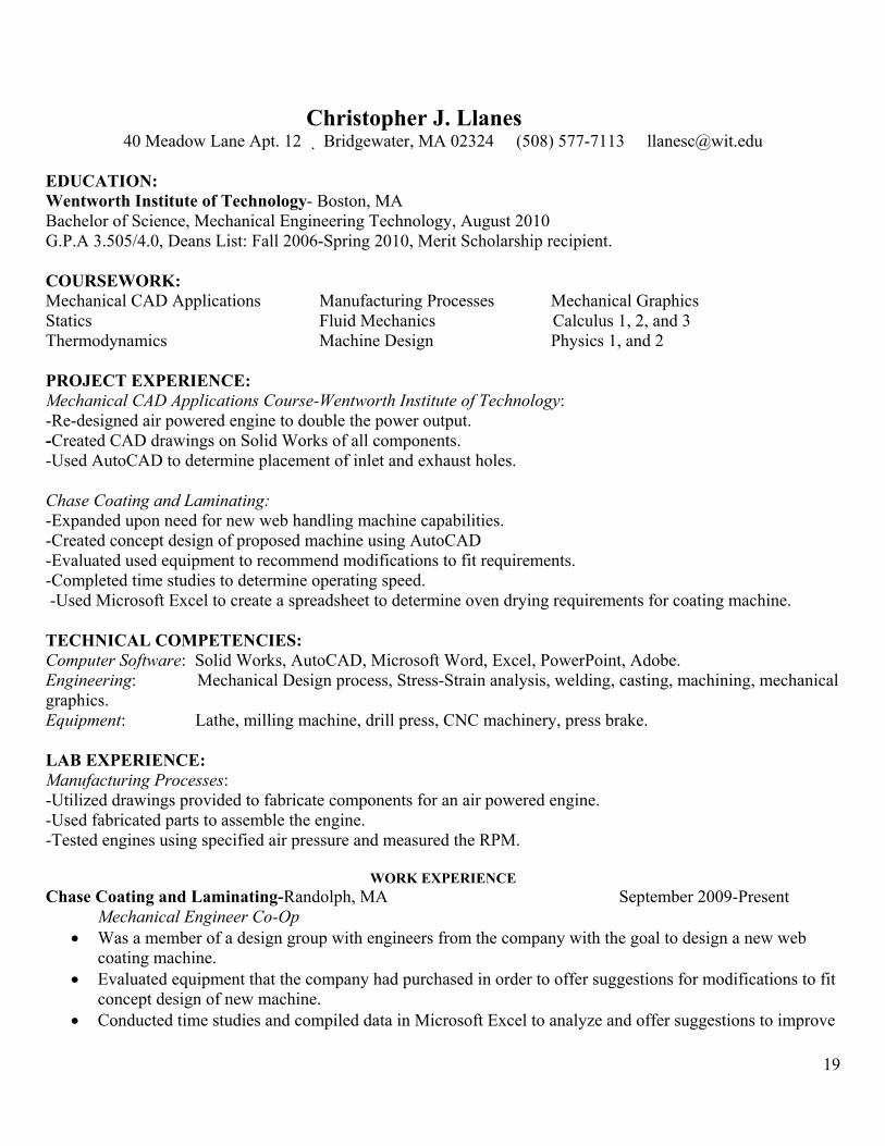
Christopher J. Llanes 40 Meadow Lane Apt. 12 ! Bridgewater, MA 02324 (508) 577-7113 [email protected]
EDUCATION: Wentworth Institute of Technology- Boston, MA Bachelor of Science, Mechanical Engineering Technology, August 2010 G.P.A 3.505/4.0, Deans List: Fall 2006-Spring 2010, Merit Scholarship recipient. COURSEWORK: Mechanical CAD Applications Manufacturing Processes Mechanical Graphics Statics Fluid Mechanics Calculus 1, 2, and 3 Thermodynamics Machine Design Physics 1, and 2 PROJECT EXPERIENCE: Mechanical CAD Applications Course-Wentworth Institute of Technology: -Re-designed air powered engine to double the power output. -Created CAD drawings on Solid Works of all components. -Used AutoCAD to determine placement of inlet and exhaust holes. Chase Coating and Laminating: -Expanded upon need for new web handling machine capabilities. -Created concept design of proposed machine using AutoCAD -Evaluated used equipment to recommend modifications to fit requirements. -Completed time studies to determine operating speed. -Used Microsoft Excel to create a spreadsheet to determine oven drying requirements for coating machine. TECHNICAL COMPETENCIES: Computer Software: Solid Works, AutoCAD, Microsoft Word, Excel, PowerPoint, Adobe. Engineering: Mechanical Design process, Stress-Strain analysis, welding, casting, machining, mechanical graphics. Equipment: Lathe, milling machine, drill press, CNC machinery, press brake. LAB EXPERIENCE: Manufacturing Processes: -Utilized drawings provided to fabricate components for an air powered engine. -Used fabricated parts to assemble the engine. -Tested engines using specified air pressure and measured the RPM.
WORK EXPERIENCE Chase Coating and Laminating-Randolph, MA September 2009-Present
Mechanical Engineer Co-Op ! Was a member of a design group with engineers from the company with the goal to design a new web
coating machine. ! Evaluated equipment that the company had purchased in order to offer suggestions for modifications to fit
concept design of new machine. ! Conducted time studies and compiled data in Microsoft Excel to analyze and offer suggestions to improve
19
current process times ! Developed a new system for physical inventory counts which saves time and improves the accuracy of
count by eliminating as much human error as possible. Depuy Orthopedics, Inc.-Raynham, MA January 2009-May 2009 Manufacturing Engineer Co-Op
! Collected, compiled, and analyzed process times from existing system in order to offer recommendations to staff structure to improve productivity.
! Restructured multiple departments by organizing tools and needed equipment to provide a safer workplace and to reduce waste.
! Teamed with associates to promote and initiate a lean manufacturing movement. ! Assisted supervisor and other co-workers in various tasks, which improved teaming skills.
Prime Glazing Co.-West Bridgewater, MA June 2008-August 2008
Laborer ! Received shipments of glass and aluminum window frames from manufacturers. ! Removed old glass and window frames in order to replace them. ! Used caulking to weatherproof window frames and glass to prevent leaks.
Venture Tape Corp.-Rockland, MA May 2006-August 2006 Maintenance Engineer
! Contacted vendors to order all parts for maintenance department. ! Utilized Purchase Order Organizer Deluxe to create purchase order sheets. ! Developed a tracking system using Excel to track all orders. ! Reviewed CAD drawings of different web handling machinery ! Helped diagnose and fix problematic web handling machinery.
Education Wentworth Institute of Technology, Boston, MA Bachelor of Science, Mechanical Engineering Technology May 2011 Coursework
Mechanical Graphics Manufacturing Processes Statics Mechanical CAD Applications Thermodynamics I Kinematics Computer Aided Manufacturing Fluid Mechanics Heat Transfer Instrumentation & Measurement Electronics & Electricity Nanotechnology Dynamics Strengths of Materials Material Science Lab Experience Manufacturing Processes -Fabricate an air driven motor using lathes and mills Mechanical Design -Devise and fabricate a ping pong ball launcher Mechanical CAD Applications -Model in Solid Works a double acting steam piston Technical Competencies
Engineering -Welding (Gas and Stick), Casting, Viscosimeter, Manometers Devices -Engine Lathe, Milling Machine, Gantry Mill, CNC Software -AutoCAD, Solid Works, CAM Works, Microsoft Word, Excel,
PowerPoint, FrontPage Project Experience Manufacturing Processes Final Project
-Fabricated, assembled, and operated an air driven piston and flywheel engine. Each piece was machined by hand and assembled to compete with other students’ motors in terms of highest RPM.
Mechanical CAD Applications
-Tasked with the redesign of the single acting piston used on the Manufacturing Processes air motor into a double acting piston using Solid Works. Our design was the presented to our fellow classmates.
Work Experience MIT Seagrant AUV Lab, Cambridge, MA January 2009-Present Assistant Research Engineer
-I assist in the design, fabrication, assembly, and maintenance of Autonomous Underwater Vehicles for various types of underwater research. I also assist in an education program called the Seaperch Institute which educates middle and high schoolers about marine engineering and underwater research.
Brigham and Women’s Hospital, Boston, MA July 2007-Present File Clerk, Department of Cardiology
-Filing of critical medical records for cardiac and cardiac transplant patients. Locating and delivering medical charts to the cardiology clinic.
Staples, Medford, MA August 2004-December 2004 Electronics Sales Associate
-General sales of business machines (Printers, Faxes, Copiers, Computers, etc.), inventory, stocking, security of merchandise.
Honors, Awards, and Leadership -Vice President of the Society of Manufacturing Engineers, Wentworth Chapter October 2008-Present
21
Timothy J. Rachielles 74 Hillside St. Apt. 3 Roxbury, MA 02120 (860) 729-0634 [email protected] www.timrachielles.com OBJECTIVE: To obtain a full time Engineering position where product development and business growth are important aspects. EDUCATION: Wentworth Institute of Technology Boston, MA Bachelors of Science in Mechanical Engineering Technology, 2010 exp. GPA: 3.0/4.0 RELEVANT COURSES: Physics I and II, Mechanical Design, Mechanical Graphics, Statics, Strengths of Materials, Thermodynamics I and II, Heat Transfer, Instrumentation and Measurements, Intro to Nanotechnology, Calculus I, II, and III, Differential Equations, Materials Science, Dynamics, Electronics MECHANICAL/DESIGN: �"Full body-off restoration of a 1990 Jeep Wrangler. �"Designed a set of defroster vents for a Jeep Wrangler to redirect air flow for more effective cabin heating. �"Machined all components to build an air motor. �"Designed and built a ping pong ball launcher. �"Designing and building patentable reclining mechanic’s creeper WORK EXPERIENCE: BioScale Inc. Cambridge, MA Spring 2009 Co-op �"Assembled BioScales Acoustic Membrane Microparticle Beta Units to be submitted for testing allowing for swift customer feedback. �"Assisted in preparing assembly instructions to decrease the amount of time required to assemble a beta unit. �"Designed and built a dust shield for testing equipment keeping the machine protected and preventing variability in the results. �"Helped develop proper assembly technique for fluidic manifolds ensuring that leaks and particulates would not affect the data. Henkel/Loctite Rocky Hill, CT Summer 2006-2008 Summer Intern �"Generated impact, tensile, and environmental aging data using Instron testers, aging equipment, and ultraviolet curing equipment for new and developmental products allowing engineers to quickly get the product ready for the market. �"Assembled customer parts with various adhesives and tested to failure, and wrote engineering reports to present to customers. �"Developed testing parameters using ASTM standards, and performed the tests, and provided results for a new Ultraviolet Cure Acrylic adhesive. Other Work Experience �"Developed skills in consumer relations through various retail positions ACHIEVEMENTS: �"Founding member of the WIT chapter of Phi Sigma Pi �"Eagle Scout Troop 23, Burlington, CT �"Global Youth Leadership Conference New York/Washington D.C. �"100 Mile Hike Philmont Scout Reservation, Cimarron , NM �"Listed in Who’s Who Among American High School Students �"Recipient of the National Federation of Independent Business’ Young Entrepreneur Scholarship
22
9.3.) Weekly Working Notes of the Group Meeting #1 – Monday, May 17th, 2010 Time: 3:20 pm – 5:20 pm Location: Beatty Library (upper level) Topic of Discussion: This meeting mainly focused on developing some ideas as to what type of mechanical design we might want to pursue. Design options that were presented are of the following:
! Automotive creeper w/ an adjustable backrest -backrest controlled pneumatically, mechanically, or hydraulically to increase human comfort and efficiency.
! Chimney turbine system -utilize the hot air from the fire in a chimney to power a turbine further up the chimney. -could be applied to a home chimney or a clothes dryer vent.
! Sink drainage power generation -drain water from home sink powers a fluid motor.
! Self car jacking system -when pulling a car over on the highway, this system could enable the driver to press a button and the car would jack itself up via a hydraulic system running off of the battery or off of the engine.
Topics for next meeting:
1.) Bring in more ideas/vote on idea.
Meeting #2 – Tuesday, May 18th, 2010
Time: 2:30 pm – 4:30 pm
Location: Beatty Library
Topic of Discussion:
The team couldn’t think of any more design options. We then held a vote for what design we wanted to pursue. The choice was: Automotive creeper w/ an adjustable backrest. We then discussed why there is a need for a product like this (Needs Assessment). Reasons brought up were: 1.) current creepers on the market require you to lift your back and adjust a steel swing arm, 2.) human ergonomic comfort can be increased. No more need to strain your neck to wrench a bolt under the car, 3.) human work efficiency can be increased, 4.) could be of interest to mechanics, especially small garage owners, racecar garages. We also discussed cost and support. We didn’t see any reason that the manufacturing of this creeper should exceed $1000. We expect it to cost a lot less to build. We have access to a garage in New Bedford, MA for the construction of it, where there is a lathe, Bridgeport, and all 3 types of welding.
23
Topics for next meeting: 1.) Develop a plan using Microsoft Project. 2.) Prepare the preproposal. Meeting #3 – Thursday, May 20th, 2010 Time: 2:30 pm – 4:30 pm Location: Beatty Library Topic of Discussion: We talked about how we will complete the pre-proposal. Tim will do the “Introduction”, Andrew will do the “Needs Assessment”, Chris will do “Predicted Results”, and I will take care of the Microsoft Project planning as well as the “Cost and Support” section. We also talked about different lifting mechanisms for the creeper’s backrest. We have many different ideas of how to build the creeper and the coming meetings will help us determine which idea works best. For next week: 1.) Complete the pre-proposal. 2.) Continue Needs Assessment and design options. 3.) Bring in some more ideas. Meeting #4 – Monday, May 24, 2010 Time: 2:15 pm – 4:15 pm Location: Beatty Library Topic of Discussion: In this meeting, we worked on the pre-proposal. We tried to figure out what we want to name this project. We talked about names such as “Versa-creep” and “Versatile Creeper”. We finally came up with “Versatile Mechanic’s Creeper.” Some minor design issues were discussed.
Topics for next meeting:
Talk about design options / finish preproposal.
Meeting #5 – Tuesday, May 25, 2010
24
Time: 2:20 pm – 3:35 pm, 3:50 – 4:35 pm
Location: Beatty Library
Topic of Discussion:
We completed and signed the pre-proposal. Also, the electronic version was submitted. We think it might be a good idea to include locking casters as well as a maximum of 30 degrees for the backrest angle. Topics for next meeting: Discuss design options in case our pre-proposal isn’t accepted. Meeting #6 – Thursday, May 27, 2010 Time: 2:30 pm – 4:30 pm Location: Cafeteria Topic of Discussion: We delegated the work for the final proposal, assuming the pre-proposal gets accepted. Andrew will add some content to the needs assessment portion. Chris will complete the design options and specifications portion. A backup idea we thought of was a jackstand with a built-in piston, where the car can be jacked up, and then the jackstand can lock into place. Design specs for the creeper were established. For next week: Complete formal proposal / start sketches and drawings for creeper. Meeting #7 – Tuesday, June 1, 2010 Time: 2:30 pm – 4:30 pm Location: Library Topic of Discussion: We set up a timeframe for when the design and analysis of the creeper needs to be completed by. We figure that it should be complete by the end of June, and then we can start building the prototype. Design criteria and specs were established and discussed.
Topics for next meeting:
25
Continue to discuss design / formal proposal status
Meeting #8 – Thursday, June 3, 2010
Time: 2:30 pm – 6:30 pm
Location: Library
Topic of Discussion:
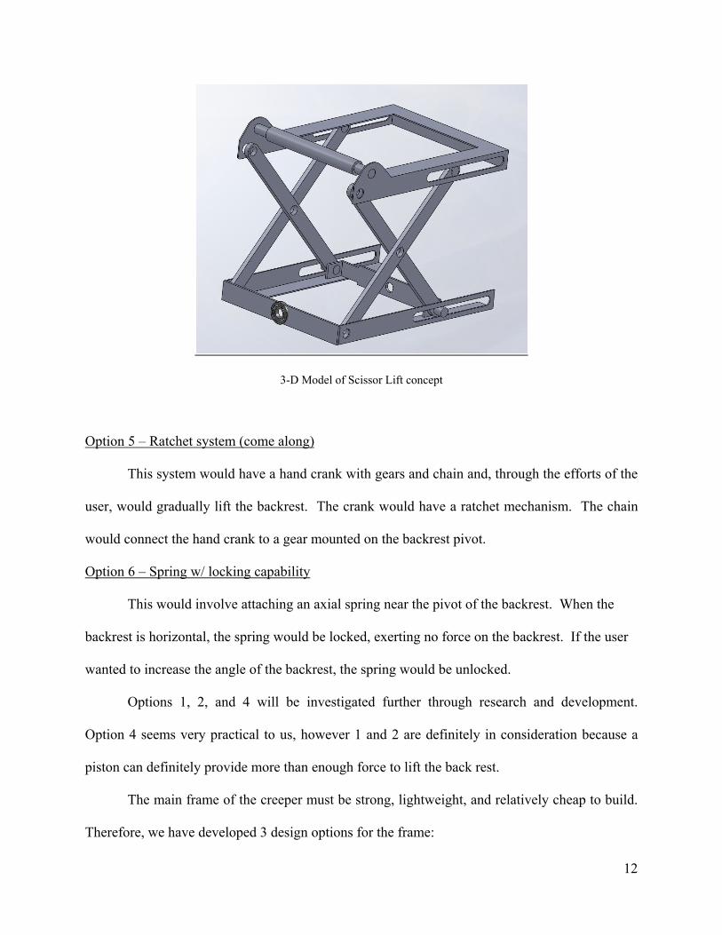
For the main frame of the creeper, a key issue that was discussed was trying to keep the weight down while keeping the integrity of the design intact. Many options were discussed and the design will be modeled in Solidworks and then analyzed for strength. A model of the scissorlift mechanism has been started and we are working to make sure that will fit into the frame properly as well as if it will be strong enough. We talked about methods to drive the scissorlift via a handcrank/driveshaft mechanism and where to install it in the frame. Also, our progress on the formal proposal was discussed. Topics for next meeting: Bring in design ideas and strength analysis results for frame. Work on formal proposal. Keep working on solid models. Meeting #9 – Monday, June 7, 2010 Time: 2:30 pm – 4:30 pm Location: Wentworth 208 Topic of Discussion: Today’s meeting was mainly focused on a design problem. How is the backrest going to attach to the frame? Also, can we get the backrest to lay flat? We drew a bunch of ideas on the board and we will put together a model on Solidworks. We thought of putting a notch in one of the main frame members in order for the backrest to lay flat. We figure ½” x ½” AISI 1020 steel tubing will work. After the back assembly is designed, we will analyze for strength. Topics for next meeting: Finish formal proposal / Finish powerpoint for thursday
Meeting #10 – Tuesday, June 8, 2010
26
Time: 2:30 pm – 4:30 pm
Location: Wentworth 208
Topic of Discussion:
Chris finished up the design specifications for the formal proposal and Andrew added some information to the needs assessment. We conducted a survey online regarding what people would like to have in a creeper. This will be included in the needs assessment. I worked on the design options section and Tim worked on the powerpoint presentation. Design ideas were also discussed regarding the backrest design. Topics for next meeting: Discuss solid model of backrest assembly / possibly conduct strength analysis. Meeting #11 – Thursday, June 10, 2010 Time: 4:30 pm – 6:30 pm Location: Beatty Library Topic of Discussion:
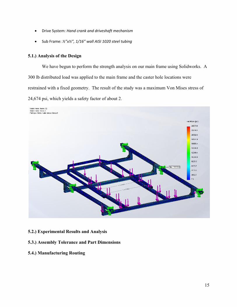
We are on track to meet our goal of designing and analyzing the creeper by the end of June. The main frame assembly is designed. We spent this meeting discussing how we will mount the scissor lift to the main frame. The goal is to have the backrest lay very close to flat when the scissor lift is completely retracted. Also, ideas were discussed regarding the drive mechanism to the scissor lift. Modeling and further development of our design will continue over the weekend and into next week. Topics for next meeting: Work on completing main frame and scissor lift assembly model / keep making design progress Meeting #12 – Monday, June 14, 2010 Time: 2:30 pm – 4:30 pm Location: Beatty Library Topic of Discussion: We conducted a strength analysis on the latest design of the main frame of the creeper. It produced a maximum stress of 27,000 psi, which gives us a 1.9 safety factor. We are making modifications to the backrest assembly to accommodate the scissorlift mechanism, as well as the linkage components that will operate it. We started to focus our attention towards the mid semester report, as it is due Thursday.
27
Topics for next meeting: Assemble, organize, and complete the mid-semester report / work on design
Meeting #13 – Tuesday, June 15, 2010
Time: 2:30 pm – 4:30 pm
Location: Wentworth 208
Topic of Discussion:
The mid-semester report was close to being complete at the meeting and will be finished by wednesday night. The scissorlift design problem has been fixed and will soon be analyzed for strength. Our main design focus has now shifted towards the drive system. Potential design problems we will face is to create a system that has a low profile, will transfer the torque effectively, as well as keep the cost at a minimum. Topics for next meeting: Bring in ideas and solutions to complete the drive system. 9.4.) Samples of Engineering Notebooks of Team Members 9.5.) Breakdown of Tasks Mathew D. Hudon
! Main frame design and analysis ! Technical report writing
Christopher J. Llanes ! Design and analysis of scissor lift mechanism ! Helping with technical reports
Andrew S. McDonough ! Design and analysis of backrest subassembly and drive system ! Helping with technical reports.
Timothy J. Rachielles ! Design and analysis of drive system and scissor lift mechanism ! Helping with technical reports.