Page 1
Dr. N. Usha Bhanu, Asso. Prof. Dr. J. Mohan, Asso. Prof. Indu Nikhil, AP (O. G)
VALLIAMMAI ENGINEERING COLLEGE SRM Nagar, Kattankulathur – 603 203.
DEPARTMENT OF ELECTRONICS & COMMUNICATION ENGINEERING
QUESTION BANK SUBJECT : EC6502- PRINCIPLES OF DIGITAL SIGNAL PROCESSING
SEM / YEAR: V/ III Year B.E.
UNIT I DISCRETE FOURIER TRANSFORM
Discrete Signals and Systems- A Review – Introduction to DFT – Properties of DFT – Circular Convolution -
Filtering methods based on DFT – FFT Algorithms –Decimation in time Algorithms, Decimation in frequency
Algorithms – Use of FFT in Linear Filtering.
PART A
Q. No Questions BT
Level Competence
1. Define DT system? BTL 1 Remembering
2. Tell DFT and IDFT? BTL 1 Remembering
3. What is meant by bit reversal? BTL 1 Remembering
4. How the zero padding occurs in circular convolution? What are its uses? BTL 1 Remembering
5. What is twiddle factor? BTL 1 Remembering
6. State Parseval’s relation with respect to DFT? BTL 1 Remembering
7. Summarize the advantages of FFT over DFTs? BTL 2 Understanding
8. How many stages of decimations are required in the case of a 64 point radix
2 DIT FFT algorithm? BTL 2 Understanding
9. What is meant by in – place computation? BTL 2 Understanding
10. Write the differences and similarities between DIT and DIF? BTL 2 Understanding
11. What is the smallest number of DFTs and IDFTs needed to compute the
linear convolution of length 50 sequences with a length of 800 sequence is
to be computed using 64 point DFT & IDFT?
BTL 3 Applying
12. Identify the differences between Overlap – add and Overlap – save method? BTL 3 Applying
13. Draw the basic butterfly diagram for the computation in the decimation in
frequency FFT algorithm and explain? BTL 3 Applying
14. Distinguish between linear convolution and circular convolution? BTL 4 Analyzing
15. List the linearity and convolution properties of DFT? BTL 4 Analyzing
16. Distinguish between DFT and FFT? BTL 4 Analyzing
Page 2
Dr. N. Usha Bhanu, Asso. Prof. Dr. J. Mohan, Asso. Prof. Indu Nikhil, AP (O. G)
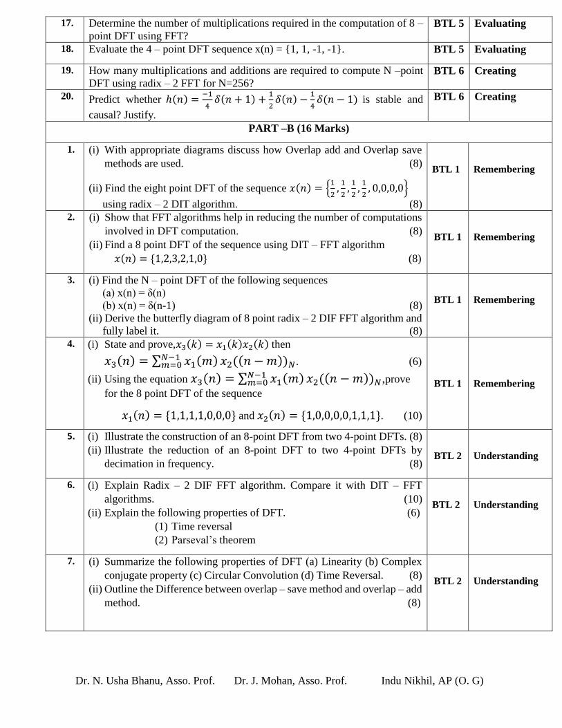
17. Determine the number of multiplications required in the computation of 8 –
point DFT using FFT? BTL 5 Evaluating
18. Evaluate the 4 – point DFT sequence x(n) = {1, 1, -1, -1}. BTL 5 Evaluating
19. How many multiplications and additions are required to compute N –point
DFT using radix – 2 FFT for N=256? BTL 6 Creating
20. Predict whether ℎ(𝑛) =−1
4𝛿(𝑛 + 1) +
1
2𝛿(𝑛) −
1
4𝛿(𝑛 − 1) is stable and
causal? Justify.
BTL 6 Creating
PART –B (16 Marks)
1. (i) With appropriate diagrams discuss how Overlap add and Overlap save
methods are used. (8)
(ii) Find the eight point DFT of the sequence 𝑥(𝑛) = {1
2,
1
2,
1
2,
1
2, 0,0,0,0}
using radix – 2 DIT algorithm. (8)
BTL 1
Remembering
2. (i) Show that FFT algorithms help in reducing the number of computations
involved in DFT computation. (8)
(ii) Find a 8 point DFT of the sequence using DIT – FFT algorithm
𝑥(𝑛) = {1,2,3,2,1,0} (8)
BTL 1
Remembering
3. 3
. (i) Find the N – point DFT of the following sequences
(a) x(n) = δ(n)
(b) x(n) = δ(n-1) (8)
(ii) Derive the butterfly diagram of 8 point radix – 2 DIF FFT algorithm and
fully label it. (8)
BTL 1
Remembering
4. 4
. (i) State and prove,𝑥3(𝑘) = 𝑥1(𝑘)𝑥2(𝑘) then
𝑥3(𝑛) = ∑ 𝑥1(𝑚)𝑁−1𝑚=0 𝑥2((𝑛 − 𝑚))𝑁. (6)
(ii) Using the equation 𝑥3(𝑛) = ∑ 𝑥1(𝑚)𝑁−1𝑚=0 𝑥2((𝑛 − 𝑚))𝑁,prove
for the 8 point DFT of the sequence
𝑥1(𝑛) = {1,1,1,1,0,0,0} and 𝑥2(𝑛) = {1,0,0,0,0,1,1,1}. (10)
BTL 1
Remembering
5. (i) Illustrate the construction of an 8-point DFT from two 4-point DFTs. (8)
(ii) Illustrate the reduction of an 8-point DFT to two 4-point DFTs by
decimation in frequency. (8)
BTL 2
Understanding
6. (i) Explain Radix – 2 DIF FFT algorithm. Compare it with DIT – FFT
algorithms. (10)
(ii) Explain the following properties of DFT. (6)
(1) Time reversal
(2) Parseval’s theorem
BTL 2
Understanding
7. (i) Summarize the following properties of DFT (a) Linearity (b) Complex
conjugate property (c) Circular Convolution (d) Time Reversal. (8)
(ii) Outline the Difference between overlap – save method and overlap – add
method. (8)
BTL 2
Understanding
Page 3
Dr. N. Usha Bhanu, Asso. Prof. Dr. J. Mohan, Asso. Prof. Indu Nikhil, AP (O. G)
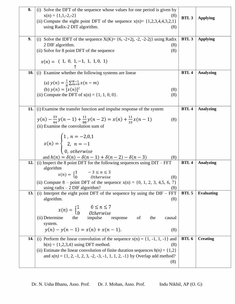
8. (i) Solve the DFT of the sequence whose values for one period is given by
x(n) = {1,1,-2,-2} (8)
(ii) Compute the eight point DFT of the sequence x(n)= {1,2,3,4,4,3,2,1}
using Radix-2 DIT algorithm. (8)
BTL 3
Applying
9. (i) Solve the IDFT of the sequence X(K)= {6, -2+2j, -2, -2-2j} using Radix
2 DIF algorithm. (8)
(ii) Solve for 8 point DFT of the sequence (8)
BTL 3 Applying
10. (i) Examine whether the following systems are linear
(a) 𝑦(𝑛) =1
𝑁∑ 𝑥(𝑛 − 𝑚)𝑁−1
𝑚=0
(b) 𝑦(𝑛) = [𝑥(𝑛)]2 (8)
(ii) Compute the DFT of x(n) = {1, 1, 0, 0}. (8)
BTL 4 Analyzing
11. (i) Examine the transfer function and impulse response of the system
𝑦(𝑛) −33
44𝑦(𝑛 − 1) +
11
88𝑦(𝑛 − 2) = 𝑥(𝑛) +
11
33𝑥(𝑛 − 1) (8)
(ii) Examine the convolution sum of
𝑥(𝑛) = {
1 , 𝑛 = −2,0,1
2, 𝑛 = −1
0, 𝑜𝑡ℎ𝑒𝑟𝑤𝑖𝑠𝑒
and ℎ(𝑛) = 𝛿(𝑛) − 𝛿(𝑛 − 1) + 𝛿(𝑛 − 2) − 𝛿(𝑛 − 3) (8)
BTL 4 Analyzing
12. (i) Inspect the 8 point DFT for the following sequences using DIT – FFT
algorithm
(8)
(ii) Compute 8 – point DFT of the sequence x(n) = {0, 1, 2, 3, 4,5, 6, 7}
using radix – 2 DIF algorithm? (8)
BTL 4 Analyzing
13. (i) Interpret the eight point DFT of the sequence by using the DIF – FFT
algorithm. (8)
(ii) Determine the impulse response of the causal
system.
𝑦(𝑛) − 𝑦(𝑛 − 1) = 𝑥(𝑛) + 𝑥(𝑛 − 1). (8)
BTL 5 Evaluating
14. (i) Perform the linear convolution of the sequence x(n) = {1, -1, 1, -1} and
h(n) = {1,2,3,4} using DFT method. (8)
(ii) Estimate the linear convolution of finite duration sequences h(n) = {1,2}
and x(n) = {1, 2, -1, 2, 3, -2, -3, -1, 1, 1, 2, -1} by Overlap add method?
(8)
BTL 6 Creating
Page 4
Dr. N. Usha Bhanu, Asso. Prof. Dr. J. Mohan, Asso. Prof. Indu Nikhil, AP (O. G)
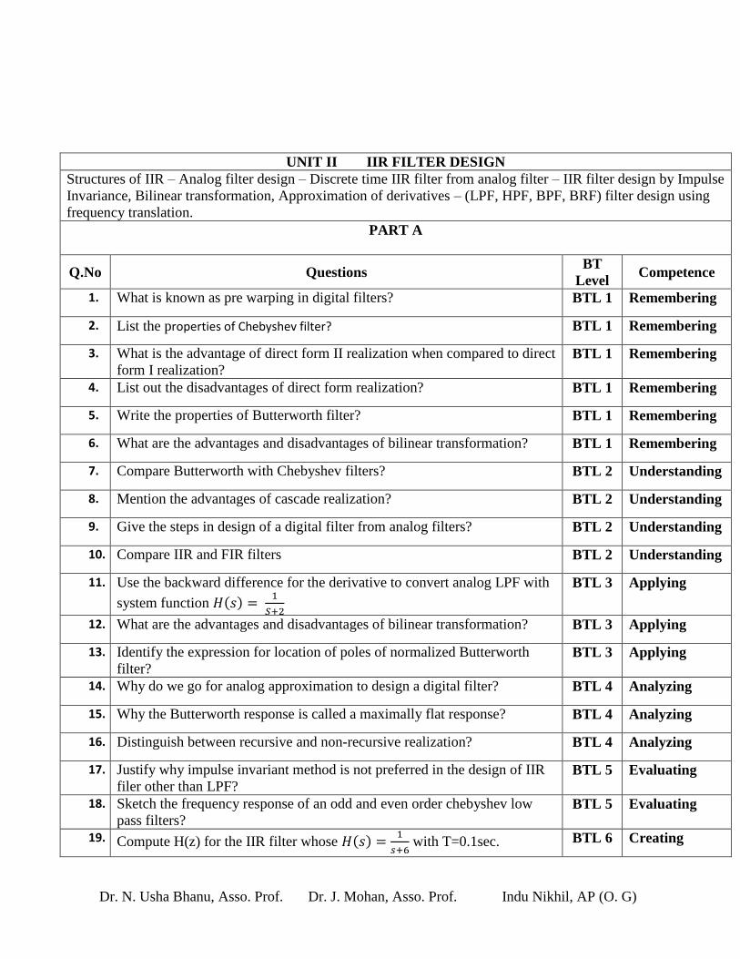
UNIT II IIR FILTER DESIGN
Structures of IIR – Analog filter design – Discrete time IIR filter from analog filter – IIR filter design by Impulse
Invariance, Bilinear transformation, Approximation of derivatives – (LPF, HPF, BPF, BRF) filter design using
frequency translation.
PART A
Q.No Questions BT
Level Competence
1. What is known as pre warping in digital filters? BTL 1 Remembering
2. List the properties of Chebyshev filter? BTL 1 Remembering
3. What is the advantage of direct form II realization when compared to direct
form I realization? BTL 1 Remembering
4. List out the disadvantages of direct form realization? BTL 1 Remembering
5. Write the properties of Butterworth filter? BTL 1 Remembering
6. What are the advantages and disadvantages of bilinear transformation? BTL 1 Remembering
7. Compare Butterworth with Chebyshev filters? BTL 2 Understanding
8. Mention the advantages of cascade realization? BTL 2 Understanding
9. Give the steps in design of a digital filter from analog filters? BTL 2 Understanding
10. Compare IIR and FIR filters BTL 2 Understanding
11. Use the backward difference for the derivative to convert analog LPF with
system function 𝐻(𝑠) = 1
𝑆+2
BTL 3 Applying
12. What are the advantages and disadvantages of bilinear transformation? BTL 3 Applying
13. Identify the expression for location of poles of normalized Butterworth
filter? BTL 3 Applying
14. Why do we go for analog approximation to design a digital filter? BTL 4 Analyzing
15. Why the Butterworth response is called a maximally flat response? BTL 4 Analyzing
16. Distinguish between recursive and non-recursive realization? BTL 4 Analyzing
17. Justify why impulse invariant method is not preferred in the design of IIR
filer other than LPF? BTL 5 Evaluating
18. Sketch the frequency response of an odd and even order chebyshev low
pass filters? BTL 5 Evaluating
19. Compute H(z) for the IIR filter whose 𝐻(𝑠) =1
𝑠+6 with T=0.1sec. BTL 6 Creating
Page 5
Dr. N. Usha Bhanu, Asso. Prof. Dr. J. Mohan, Asso. Prof. Indu Nikhil, AP (O. G)
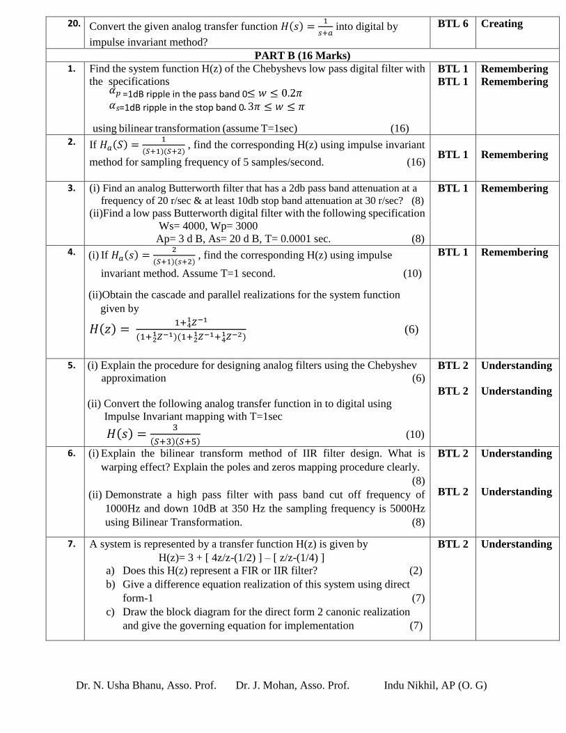
20. Convert the given analog transfer function 𝐻(𝑠) =1
𝑠+𝑎 into digital by
impulse invariant method?
BTL 6 Creating
PART B (16 Marks)
1. Find the system function H(z) of the Chebyshevs low pass digital filter with
the specifications =1dB ripple in the pass band 0
=1dB ripple in the stop band 0
using bilinear transformation (assume T=1sec) (16)
BTL 1
BTL 1
Remembering
Remembering
2. If 𝐻𝑎(𝑆) =1
(𝑆+1)(𝑆+2) , find the corresponding H(z) using impulse invariant
method for sampling frequency of 5 samples/second. (16)
BTL 1
Remembering
3. (i) Find an analog Butterworth filter that has a 2db pass band attenuation at a
frequency of 20 r/sec & at least 10db stop band attenuation at 30 r/sec? (8)
(ii)Find a low pass Butterworth digital filter with the following specification
Ws= 4000, Wp= 3000
Ap= 3 d B, As= 20 d B, T= 0.0001 sec. (8)
BTL 1 Remembering
4. (i) If 𝐻𝑎(𝑠) =2
(𝑆+1)(𝑠+2) , find the corresponding H(z) using impulse
invariant method. Assume T=1 second. (10)
(ii)Obtain the cascade and parallel realizations for the system function
given by
𝐻(𝑧) = 1+ 𝑍−1
41
(1+ 𝑍−1)(1+ 𝑍−1+ 𝑍−2)41
21
21 (6)
BTL 1 Remembering
5. (i) Explain the procedure for designing analog filters using the Chebyshev
approximation (6)
(ii) Convert the following analog transfer function in to digital using
Impulse Invariant mapping with T=1sec
𝐻(𝑠) =3
(𝑆+3)(𝑆+5) (10)
BTL 2
BTL 2
Understanding
Understanding
6. (i) Explain the bilinear transform method of IIR filter design. What is
warping effect? Explain the poles and zeros mapping procedure clearly.
(8)
(ii) Demonstrate a high pass filter with pass band cut off frequency of
1000Hz and down 10dB at 350 Hz the sampling frequency is 5000Hz
using Bilinear Transformation. (8)
BTL 2
BTL 2
Understanding
Understanding
7. A system is represented by a transfer function H(z) is given by
H(z)= 3 + [ 4z/z-(1/2) ] – [ z/z-(1/4) ]
a) Does this H(z) represent a FIR or IIR filter? (2)
b) Give a difference equation realization of this system using direct
form-1 (7)
c) Draw the block diagram for the direct form 2 canonic realization
and give the governing equation for implementation (7)
BTL 2 Understanding
Page 6
Dr. N. Usha Bhanu, Asso. Prof. Dr. J. Mohan, Asso. Prof. Indu Nikhil, AP (O. G)
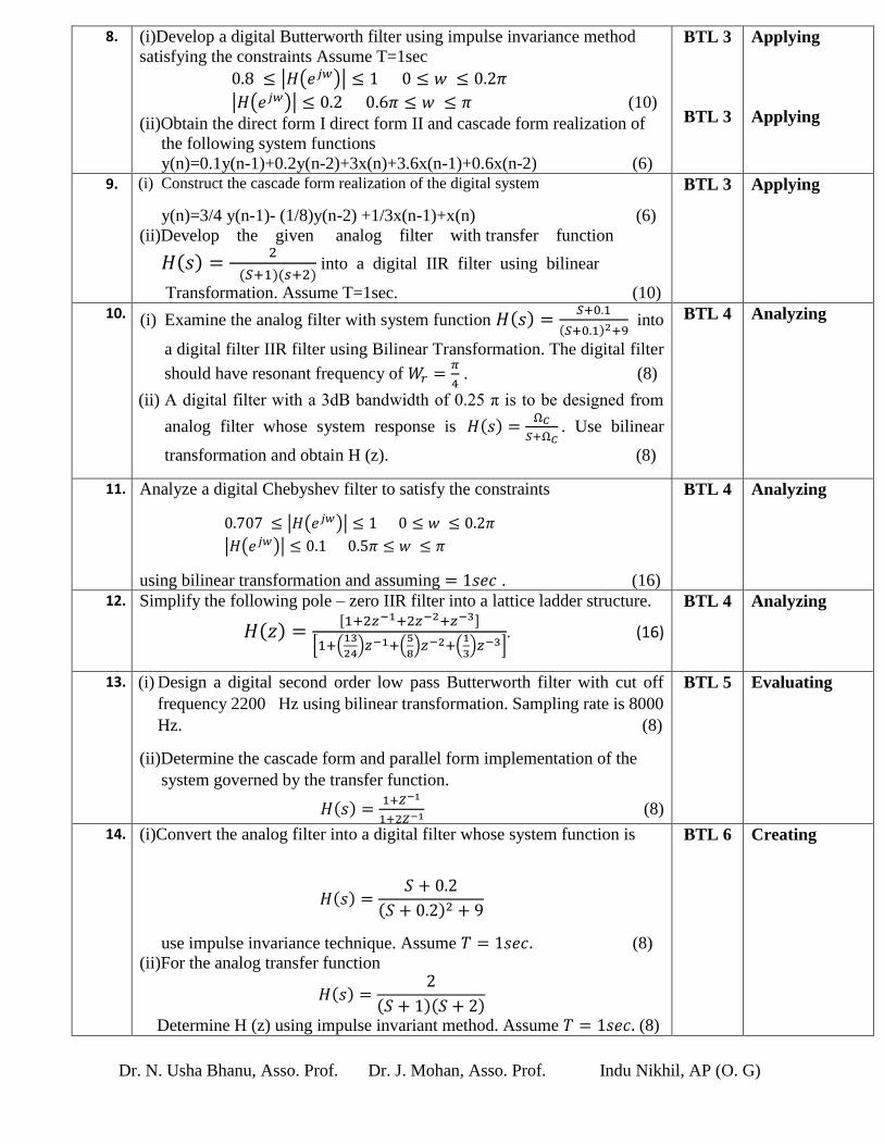
8. (i)Develop a digital Butterworth filter using impulse invariance method
satisfying the constraints Assume T=1sec
0.8 ≤ |𝐻(𝑒𝑗𝑤)| ≤ 1 0 ≤ 𝑤 ≤ 0.2𝜋
|𝐻(𝑒𝑗𝑤)| ≤ 0.2 0.6𝜋 ≤ 𝑤 ≤ 𝜋 (10)
(ii)Obtain the direct form I direct form II and cascade form realization of
the following system functions
y(n)=0.1y(n-1)+0.2y(n-2)+3x(n)+3.6x(n-1)+0.6x(n-2) (6)
BTL 3
BTL 3
Applying
Applying
9. (i) Construct the cascade form realization of the digital system
y(n)=3/4 y(n-1)- (1/8)y(n-2) +1/3x(n-1)+x(n) (6)
(ii)Develop the given analog filter with transfer function
𝐻(𝑠) =2
(𝑆+1)(𝑠+2) into a digital IIR filter using bilinear
Transformation. Assume T=1sec. (10)
BTL 3 Applying
10. (i) Examine the analog filter with system function 𝐻(𝑠) =𝑆+0.1
(𝑆+0.1)2+9 into
a digital filter IIR filter using Bilinear Transformation. The digital filter
should have resonant frequency of 𝑊𝑟 =𝜋
4 . (8)
(ii) A digital filter with a 3dB bandwidth of 0.25 π is to be designed from
analog filter whose system response is 𝐻(𝑠) =Ω𝐶
𝑆+Ω𝐶. Use bilinear
transformation and obtain H (z). (8)
BTL 4 Analyzing
11. Analyze a digital Chebyshev filter to satisfy the constraints
0.707 ≤ |𝐻(𝑒𝑗𝑤)| ≤ 1 0 ≤ 𝑤 ≤ 0.2𝜋
|𝐻(𝑒𝑗𝑤)| ≤ 0.1 0.5𝜋 ≤ 𝑤 ≤ 𝜋
using bilinear transformation and assuming = 1𝑠𝑒𝑐 . (16)
BTL 4
Analyzing
12. Simplify the following pole – zero IIR filter into a lattice ladder structure.
𝐻(𝑧) =[1+2𝑧−1+2𝑧−2+𝑧−3]
[1+(13
24)𝑧−1+(
5
8)𝑧−2+(
1
3)𝑧−3]
. (16)
BTL 4 Analyzing
13. (i) Design a digital second order low pass Butterworth filter with cut off
frequency 2200 Hz using bilinear transformation. Sampling rate is 8000
Hz. (8)
(ii)Determine the cascade form and parallel form implementation of the
system governed by the transfer function.
𝐻(𝑠) =1+𝑍−1
1+2𝑍−1 (8)
BTL 5 Evaluating
14. (i)Convert the analog filter into a digital filter whose system function is
𝐻(𝑠) =𝑆 + 0.2
(𝑆 + 0.2)2 + 9
use impulse invariance technique. Assume 𝑇 = 1𝑠𝑒𝑐. (8)
(ii)For the analog transfer function
𝐻(𝑠) =2
(𝑆 + 1)(𝑆 + 2)
Determine H (z) using impulse invariant method. Assume 𝑇 = 1𝑠𝑒𝑐. (8)
BTL 6
Creating
Page 7
Dr. N. Usha Bhanu, Asso. Prof. Dr. J. Mohan, Asso. Prof. Indu Nikhil, AP (O. G)
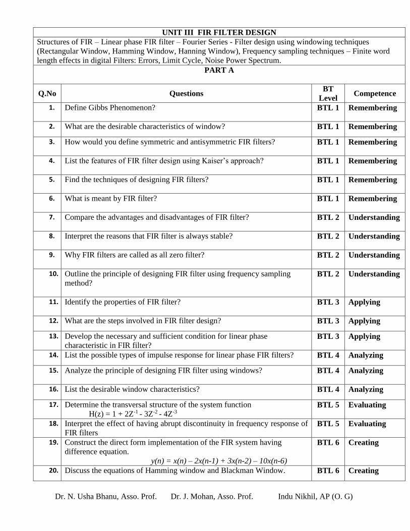
UNIT III FIR FILTER DESIGN
Structures of FIR – Linear phase FIR filter – Fourier Series - Filter design using windowing techniques
(Rectangular Window, Hamming Window, Hanning Window), Frequency sampling techniques – Finite word
length effects in digital Filters: Errors, Limit Cycle, Noise Power Spectrum.
PART A
Q.No Questions BT
Level Competence
1. Define Gibbs Phenomenon?
BTL 1 Remembering
2. What are the desirable characteristics of window? BTL 1 Remembering
3. How would you define symmetric and antisymmetric FIR filters?
BTL 1 Remembering
4. List the features of FIR filter design using Kaiser’s approach?
BTL 1 Remembering
5. Find the techniques of designing FIR filters?
BTL 1 Remembering
6. What is meant by FIR filter?
BTL 1 Remembering
7. Compare the advantages and disadvantages of FIR filter?
BTL 2 Understanding
8. Interpret the reasons that FIR filter is always stable?
BTL 2 Understanding
9. Why FIR filters are called as all zero filter?
BTL 2 Understanding
10. Outline the principle of designing FIR filter using frequency sampling
method?
BTL 2 Understanding
11. Identify the properties of FIR filter?
BTL 3 Applying
12. What are the steps involved in FIR filter design? BTL 3 Applying
13. Develop the necessary and sufficient condition for linear phase
characteristic in FIR filter? BTL 3 Applying
14. List the possible types of impulse response for linear phase FIR filters? BTL 4 Analyzing
15. Analyze the principle of designing FIR filter using windows?
BTL 4 Analyzing
16. List the desirable window characteristics? BTL 4 Analyzing
17. Determine the transversal structure of the system function
H(z) = 1 + 2Z-1 - 3Z-2 - 4Z-3 BTL 5 Evaluating
18. Interpret the effect of having abrupt discontinuity in frequency response of
FIR filters BTL 5 Evaluating
19. Construct the direct form implementation of the FIR system having
difference equation.
y(n) = x(n) – 2x(n-1) + 3x(n-2) – 10x(n-6)
BTL 6 Creating
20. Discuss the equations of Hamming window and Blackman Window. BTL 6 Creating
Page 8
Dr. N. Usha Bhanu, Asso. Prof. Dr. J. Mohan, Asso. Prof. Indu Nikhil, AP (O. G)
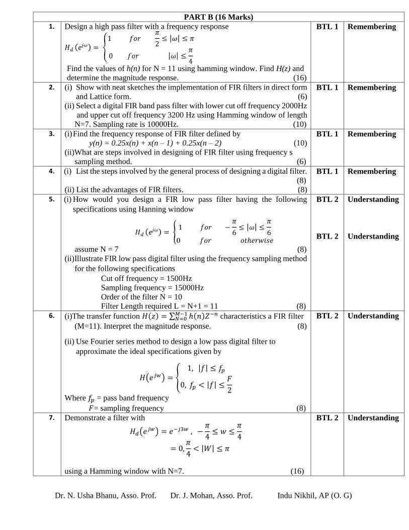
PART B (16 Marks)
1. Design a high pass filter with a frequency response
Find the values of h(n) for N = 11 using hamming window. Find H(z) and
determine the magnitude response. (16)
BTL 1 Remembering
2. (i) Show with neat sketches the implementation of FIR filters in direct form
and Lattice form. (6)
(ii) Select a digital FIR band pass filter with lower cut off frequency 2000Hz
and upper cut off frequency 3200 Hz using Hamming window of length
N=7. Sampling rate is 10000Hz. (10)
BTL 1 Remembering
3. (i) Find the frequency response of FIR filter defined by
y(n) = 0.25x(n) + x(n – 1) + 0.25x(n – 2) (10)
(ii)What are steps involved in designing of FIR filter using frequency s
sampling method. (6)
BTL 1 Remembering
4. (i) List the steps involved by the general process of designing a digital filter.
(8)
(ii) List the advantages of FIR filters. (8)
BTL 1 Remembering
5. (i) How would you design a FIR low pass filter having the following
specifications using Hanning window
assume N = 7 (8)
(ii)Illustrate FIR low pass digital filter using the frequency sampling method
for the following specifications
Cut off frequency = 1500Hz
Sampling frequency = 15000Hz
Order of the filter N = 10
Filter Length required L = N+1 = 11 (8)
BTL 2
BTL 2
Understanding
Understanding
6. (i)The transfer function 𝐻(𝑧) = ∑ ℎ(𝑛)𝑍−𝑛𝑀−1𝑁=0 characteristics a FIR filter
(M=11). Interpret the magnitude response. (8)
(ii) Use Fourier series method to design a low pass digital filter to
approximate the ideal specifications given by
𝐻(𝑒𝑗𝑤) = {1, |𝑓| ≤ 𝑓𝑝
0, 𝑓𝑝 < |𝑓| ≤𝐹
2
Where 𝑓𝑝 = pass band frequency
𝐹= sampling frequency (8)
BTL 2 Understanding
7. Demonstrate a filter with
𝐻𝑑(𝑒𝑗𝑤) = 𝑒−𝑗3𝑤 , −𝜋
4≤ 𝑤 ≤
𝜋
4
= 0,𝜋
4< |𝑊| ≤ 𝜋
using a Hamming window with N=7. (16)
BTL 2 Understanding
Page 9
Dr. N. Usha Bhanu, Asso. Prof. Dr. J. Mohan, Asso. Prof. Indu Nikhil, AP (O. G)
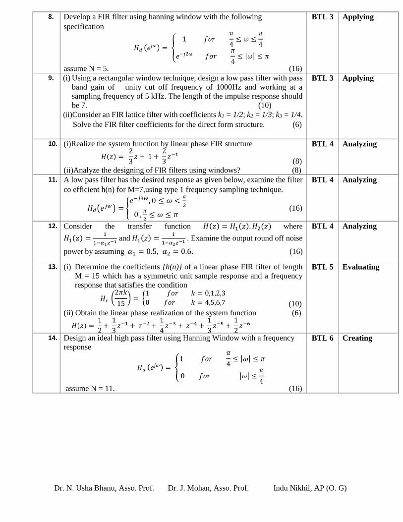
8. Develop a FIR filter using hanning window with the following
specification
assume N = 5. (16)
BTL 3 Applying
9. (i) Using a rectangular window technique, design a low pass filter with pass
band gain of unity cut off frequency of 1000Hz and working at a
sampling frequency of 5 kHz. The length of the impulse response should
be 7. (10)
(ii)Consider an FIR lattice filter with coefficients k1 = 1/2; k2 = 1/3; k3 = 1/4.
Solve the FIR filter coefficients for the direct form structure. (6)
BTL 3 Applying
10. (i)Realize the system function by linear phase FIR structure
(8)
(ii)Analyze the designing of FIR filters using windows? (8)
BTL 4 Analyzing
11. A low pass filter has the desired response as given below, examine the filter
co efficient h(n) for M=7,using type 1 frequency sampling technique.
𝐻𝑑(𝑒𝑗𝑤) = {𝑒−𝑗3𝑤, 0 ≤ 𝜔 <
𝜋
2
0 ,𝜋
2≤ 𝜔 ≤ 𝜋
(16)
BTL 4 Analyzing
12. Consider the transfer function 𝐻(𝑧) = 𝐻1(𝑧). 𝐻2(𝑧) where
𝐻1(𝑧) =1
1−𝛼1𝑧−1 and 𝐻1(𝑧) =1
1−𝛼2𝑧−1 . Examine the output round off noise
power by assuming 𝛼1 = 0.5, 𝛼2 = 0.6. (16)
BTL 4 Analyzing
13. (i) Determine the coefficients {h(n)} of a linear phase FIR filter of length
M = 15 which has a symmetric unit sample response and a frequency
response that satisfies the condition
(10)
(ii) Obtain the linear phase realization of the system function (6)
BTL 5 Evaluating
14. Design an ideal high pass filter using Hanning Window with a frequency
response
assume N = 11. (16)
BTL 6 Creating
Page 10
Dr. N. Usha Bhanu, Asso. Prof. Dr. J. Mohan, Asso. Prof. Indu Nikhil, AP (O. G)
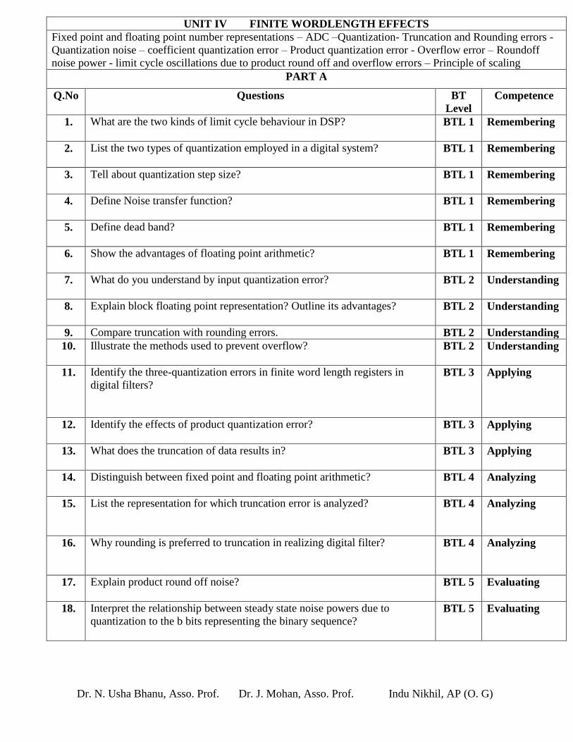
UNIT IV FINITE WORDLENGTH EFFECTS
Fixed point and floating point number representations – ADC –Quantization- Truncation and Rounding errors -
Quantization noise – coefficient quantization error – Product quantization error - Overflow error – Roundoff
noise power - limit cycle oscillations due to product round off and overflow errors – Principle of scaling
PART A
Q.No Questions BT
Level
Competence
1. What are the two kinds of limit cycle behaviour in DSP?
BTL 1 Remembering
2. List the two types of quantization employed in a digital system?
BTL 1 Remembering
3. Tell about quantization step size?
BTL 1 Remembering
4. Define Noise transfer function?
BTL 1 Remembering
5. Define dead band?
BTL 1 Remembering
6. Show the advantages of floating point arithmetic?
BTL 1 Remembering
7. What do you understand by input quantization error?
BTL 2 Understanding
8. Explain block floating point representation? Outline its advantages?
BTL 2 Understanding
9. Compare truncation with rounding errors. BTL 2 Understanding
10. Illustrate the methods used to prevent overflow?
BTL 2 Understanding
11. Identify the three-quantization errors in finite word length registers in
digital filters?
BTL 3 Applying
12. Identify the effects of product quantization error?
BTL 3 Applying
13. What does the truncation of data results in?
BTL 3 Applying
14. Distinguish between fixed point and floating point arithmetic?
BTL 4 Analyzing
15. List the representation for which truncation error is analyzed?
BTL 4 Analyzing
16. Why rounding is preferred to truncation in realizing digital filter?
BTL 4 Analyzing
17. Explain product round off noise?
BTL 5 Evaluating
18. Interpret the relationship between steady state noise powers due to
quantization to the b bits representing the binary sequence?
BTL 5 Evaluating
Page 11
Dr. N. Usha Bhanu, Asso. Prof. Dr. J. Mohan, Asso. Prof. Indu Nikhil, AP (O. G)
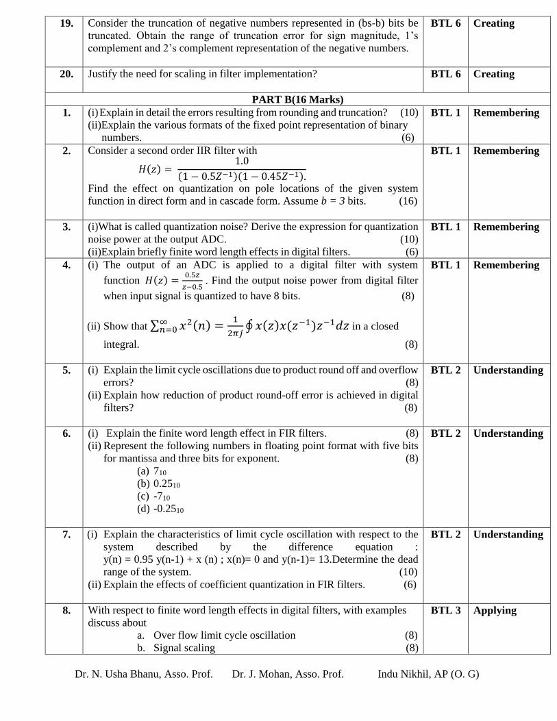
19. Consider the truncation of negative numbers represented in (bs-b) bits be
truncated. Obtain the range of truncation error for sign magnitude, 1’s
complement and 2’s complement representation of the negative numbers.
BTL 6 Creating
20. Justify the need for scaling in filter implementation?
BTL 6 Creating
PART B(16 Marks)
1. (i) Explain in detail the errors resulting from rounding and truncation? (10)
(ii)Explain the various formats of the fixed point representation of binary
numbers. (6)
BTL 1 Remembering
2. Consider a second order IIR filter with
Find the effect on quantization on pole locations of the given system
function in direct form and in cascade form. Assume b = 3 bits. (16)
BTL 1 Remembering
3. (i)What is called quantization noise? Derive the expression for quantization
noise power at the output ADC. (10)
(ii)Explain briefly finite word length effects in digital filters. (6)
BTL 1 Remembering
4. (i) The output of an ADC is applied to a digital filter with system
function 𝐻(𝑧) =0.5𝑧
𝑧−0.5 . Find the output noise power from digital filter
when input signal is quantized to have 8 bits. (8)
(ii) Show that ∑ 𝑥2(𝑛) =1
2𝜋𝑗∮ 𝑥(𝑧)𝑥(𝑧−1)𝑧−1𝑑𝑧∞
𝑛=0 in a closed
integral. (8)
BTL 1 Remembering
5. (i) Explain the limit cycle oscillations due to product round off and overflow
errors? (8)
(ii) Explain how reduction of product round-off error is achieved in digital
filters? (8)
BTL 2 Understanding
6. (i) Explain the finite word length effect in FIR filters. (8)
(ii) Represent the following numbers in floating point format with five bits
for mantissa and three bits for exponent. (8)
(a) 710
(b) 0.2510
(c) -710
(d) -0.2510
BTL 2 Understanding
7. (i) Explain the characteristics of limit cycle oscillation with respect to the
system described by the difference equation :
y(n) = 0.95 y(n-1) + x (n) ; x(n)= 0 and y(n-1)= 13.Determine the dead
range of the system. (10)
(ii) Explain the effects of coefficient quantization in FIR filters. (6)
BTL 2 Understanding
8. With respect to finite word length effects in digital filters, with examples
discuss about
a. Over flow limit cycle oscillation (8)
b. Signal scaling (8)
BTL 3 Applying
Page 12
Dr. N. Usha Bhanu, Asso. Prof. Dr. J. Mohan, Asso. Prof. Indu Nikhil, AP (O. G)
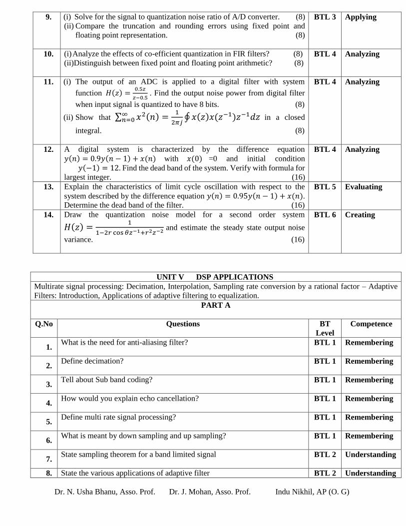
9. (i) Solve for the signal to quantization noise ratio of A/D converter. (8)
(ii) Compare the truncation and rounding errors using fixed point and
floating point representation. (8)
BTL 3 Applying
10. (i) Analyze the effects of co-efficient quantization in FIR filters? (8)
(ii)Distinguish between fixed point and floating point arithmetic? (8)
BTL 4
Analyzing
11. (i) The output of an ADC is applied to a digital filter with system
function 𝐻(𝑧) =0.5𝑧
𝑧−0.5 . Find the output noise power from digital filter
when input signal is quantized to have 8 bits. (8)
(ii) Show that ∑ 𝑥2(𝑛) =1
2𝜋𝑗∮ 𝑥(𝑧)𝑥(𝑧−1)𝑧−1𝑑𝑧∞
𝑛=0 in a closed
integral. (8)
BTL 4
Analyzing
12. A digital system is characterized by the difference equation
𝑦(𝑛) = 0.9𝑦(𝑛 − 1) + 𝑥(𝑛) with 𝑥(0) =0 and initial condition
𝑦(−1) = 12. Find the dead band of the system. Verify with formula for
largest integer. (16)
BTL 4
Analyzing
13. Explain the characteristics of limit cycle oscillation with respect to the
system described by the difference equation 𝑦(𝑛) = 0.95𝑦(𝑛 − 1) + 𝑥(𝑛).
Determine the dead band of the filter. (16)
BTL 5
Evaluating
14. Draw the quantization noise model for a second order system
𝐻(𝑧) =1
1−2𝑟 cos 𝜃𝑧−1+𝑟2𝑧−2 and estimate the steady state output noise
variance. (16)
BTL 6
Creating
UNIT V DSP APPLICATIONS
Multirate signal processing: Decimation, Interpolation, Sampling rate conversion by a rational factor – Adaptive
Filters: Introduction, Applications of adaptive filtering to equalization.
PART A
Q.No Questions BT
Level
Competence
1. What is the need for anti-aliasing filter?
BTL 1 Remembering
2. Define decimation?
BTL 1 Remembering
3. Tell about Sub band coding?
BTL 1 Remembering
4. How would you explain echo cancellation?
BTL 1 Remembering
5. Define multi rate signal processing?
BTL 1 Remembering
6. What is meant by down sampling and up sampling?
BTL 1 Remembering
7. State sampling theorem for a band limited signal
BTL 2 Understanding
8. State the various applications of adaptive filter BTL 2 Understanding
Page 13
Dr. N. Usha Bhanu, Asso. Prof. Dr. J. Mohan, Asso. Prof. Indu Nikhil, AP (O. G)
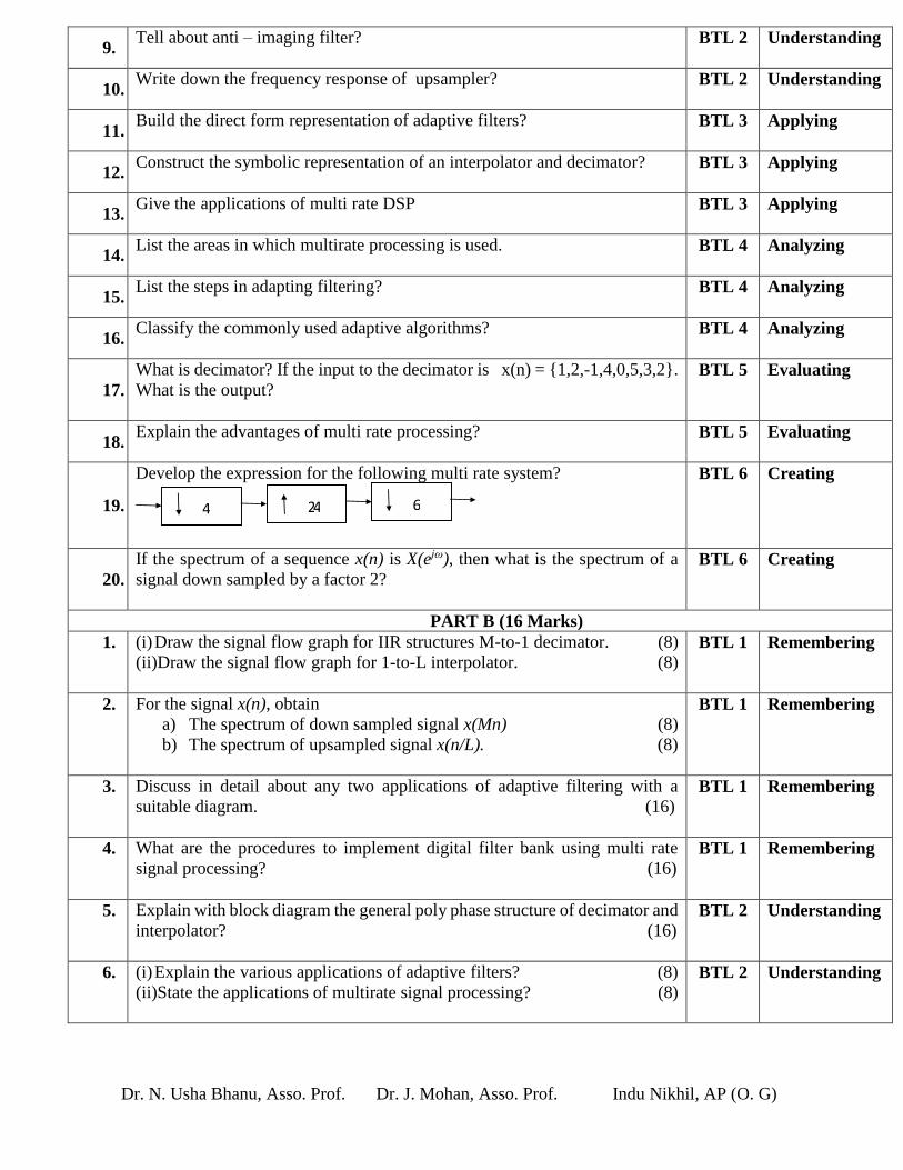
9. Tell about anti – imaging filter?
BTL 2 Understanding
10. Write down the frequency response of upsampler?
BTL 2 Understanding
11. Build the direct form representation of adaptive filters?
BTL 3 Applying
12. Construct the symbolic representation of an interpolator and decimator?
BTL 3 Applying
13. Give the applications of multi rate DSP
BTL 3 Applying
14. List the areas in which multirate processing is used.
BTL 4 Analyzing
15. List the steps in adapting filtering?
BTL 4 Analyzing
16. Classify the commonly used adaptive algorithms?
BTL 4 Analyzing
17. What is decimator? If the input to the decimator is x(n) = {1,2,-1,4,0,5,3,2}.
What is the output?
BTL 5 Evaluating
18. Explain the advantages of multi rate processing?
BTL 5 Evaluating
19.
Develop the expression for the following multi rate system?
BTL 6 Creating
20. If the spectrum of a sequence x(n) is X(ejω), then what is the spectrum of a
signal down sampled by a factor 2?
BTL 6 Creating
PART B (16 Marks)
1. (i) Draw the signal flow graph for IIR structures M-to-1 decimator. (8)
(ii)Draw the signal flow graph for 1-to-L interpolator. (8)
BTL 1 Remembering
2. For the signal x(n), obtain
a) The spectrum of down sampled signal x(Mn) (8)
b) The spectrum of upsampled signal x(n/L). (8)
BTL 1 Remembering
3. Discuss in detail about any two applications of adaptive filtering with a
suitable diagram. (16)
BTL 1 Remembering
4. What are the procedures to implement digital filter bank using multi rate
signal processing? (16)
BTL 1 Remembering
5. Explain with block diagram the general poly phase structure of decimator and
interpolator? (16)
BTL 2 Understanding
6. (i) Explain the various applications of adaptive filters? (8)
(ii)State the applications of multirate signal processing? (8)
BTL 2 Understanding
4 2 4 6
Page 14
Dr. N. Usha Bhanu, Asso. Prof. Dr. J. Mohan, Asso. Prof. Indu Nikhil, AP (O. G)
7. (i) Explain the design of narrow band filter using sampling rate
conversion. (8) (ii) Explain the design steps involved in the implementation of multistage
sampling rate converter. (8)
BTL 2 Understanding
8. A signal x(n) is given by x(n) = {0,1,2,3,4,5,6,0,1,2,3….}
i) Obtain the decimated signal with a factor of 2. (8)
ii)Obtain the interpolated signal with a factor of 2. (8)
BTL 3 Applying
9. (i) Obtain the decimated signal y(n) by a factor 3 from the input signal x(n). (8)
(ii)Implement a 2-stage decimator for the following specification:
Sampling rate of the input signal =20 kHz, M=100.
Pass band= 0 to 40 Hz
Transition band = 40 to 50 Hz
Pass band ripple = 0.01
Stop band ripple = 0.002. (8)
BTL 3 Applying
10. List the applications of adaptive filters in:
(i) Echo cancellation (8)
(ii) Equalization. (8)
BTL 4 Analyzing
11. (i) Analyze the efficient transversal structure for decimator and
interpolator? (10)
(ii) What are the applications of MDSP in sub band coding of signals? (6)
BTL 4 Analyzing
12. Explain sampling rate conversion by a rational factor and derive input and
output relation in both time and frequency domain. (16)
BTL 4 Analyzing
13. (i) Explain in detail the two basic operations in multi rate signal processor. (8)
(ii) Explain the efficient implementation of polyphase decimator and
interpolator. (8)
BTL 5 Evaluating
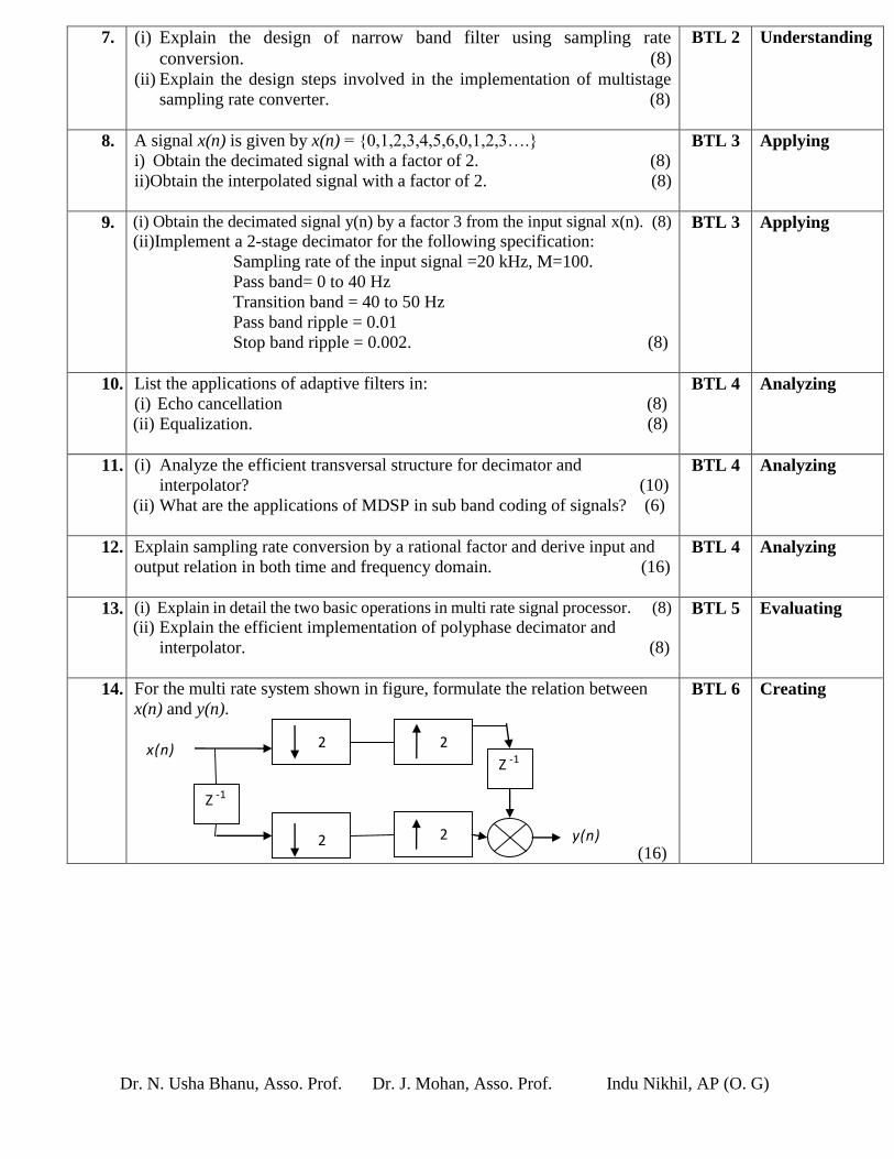
14. For the multi rate system shown in figure, formulate the relation between
x(n) and y(n).
(16)
BTL 6 Creating
2
2
2
2
Z - 1
Z - 1
y ( n )
x n ( )