DEPARTMENT OF ENVIRONMENTAL QUALITY DIVISION OF AIR QUALITY Permit Application Analysis A0001250 September 11, 2015 NAME OF FIRM: QEPM Gathering I, LLC MAILING ADDRESS: 1050 17 th Street, Suite 800 Denver, CO 80265 RESPONSIBLE OFFICIAL: Daniel Pring Senior Environmental Air Engineer TELEPHONE NUMBER: (303) 640-4238 TYPE OF OPERATION: multiple well, dehydration unit FACILITY NAME: Mesa 8-17 PAD FACILITY LOCATION: SE¼ NE¼ Section 17, T32N, R109W Latitude: 42.74889° Longitude: -109.85027° Sublette County, Wyoming DATE FACILITY BECAME OPERATIONAL: 12/7/2001, startup of Mesa 8-17 well site 5/7/2015, equipment split from QEP Energy Company REVIEWER: Heather Bleile, Air Quality Engineer PURPOSE OF APPLICATION: QEPM Gathering I, LLC filed this application to modify the Mesa 8- 17 PAD by replacing the 40 MMCFD dehydration unit with a 10 MMCFD dehydration unit and with the removal of a line heater and pneumatic pump. The dehydration unit processes gas from the Mesa 8-17, 1C1-17, 1D1-17, 2D1-17, 4C1-16, 4C2-16, 5B1- 16, 5B2-16, 7A1-17, 8A1-17, 8B1-17, 8D1-17, 8D2-17, 9B1-17 and 9C1-17 well sites. PERMIT HISTORY: The Mesa 8-17 PAD currently operates under Air Quality Permit, P0018889, issued August 13, 2015. A smokeless combustion device was required to control volatile organic compound (VOC) and hazardous air pollutant (HAP) emissions associated with the dehydration unit. This permit shall supersede P0018889 for the dehydration unit at the Mesa 8-17 PAD.
Transcript
DEPARTMENT OF ENVIRONMENTAL QUALITY
DIVISION OF AIR QUALITY
Permit Application Analysis
A0001250
September 11, 2015
NAME OF FIRM: QEPM Gathering I, LLC
MAILING ADDRESS: 1050 17th Street, Suite 800
Denver, CO 80265
RESPONSIBLE OFFICIAL: Daniel Pring
Senior Environmental Air Engineer
TELEPHONE NUMBER: (303) 640-4238
TYPE OF OPERATION: multiple well, dehydration unit
OPERATIONAL: 12/7/2001, startup of Mesa 8-17 well site
5/7/2015, equipment split from QEP Energy Company
REVIEWER: Heather Bleile, Air Quality Engineer
PURPOSE OF APPLICATION: QEPM Gathering I, LLC filed this application to modify the Mesa 8-
17 PAD by replacing the 40 MMCFD dehydration unit with a 10 MMCFD dehydration unit and with the
removal of a line heater and pneumatic pump.
The dehydration unit processes gas from the Mesa 8-17, 1C1-17, 1D1-17, 2D1-17, 4C1-16, 4C2-16, 5B1-
16, 5B2-16, 7A1-17, 8A1-17, 8B1-17, 8D1-17, 8D2-17, 9B1-17 and 9C1-17 well sites.
PERMIT HISTORY: The Mesa 8-17 PAD currently operates under Air Quality Permit, P0018889,
issued August 13, 2015. A smokeless combustion device was required to control volatile organic
compound (VOC) and hazardous air pollutant (HAP) emissions associated with the dehydration unit.
This permit shall supersede P0018889 for the dehydration unit at the Mesa 8-17 PAD.
QEPM Gathering I, LLC
A0001250 Permit Application Analysis
Page 2
The following equipment operates at the Mesa 8-17 PAD:
one (1) three-phase high pressure (HP) separator
one (1) 10.0 million cubic feet per day (MMCFD) triethylene glycol (TEG) dehydration unit w/
Kimray Model 9015PV glycol pump, 0.125 million Btu per hour (MMBtu/hr) reboiler heater, reboiler
overheads condenser and TEG flash separator
four (4) low-bleed pneumatic liquid level controllers
one (1) smokeless combustion device w/ continuous pilot monitoring system (controls non-
condensable reboiler and TEG flash separator emissions)
one (1) 300-barrel (bbl) test tank (owned and operated by QEP Energy Company, shared by QEPM)
For the modifications described under this permit, involving the installation of equipment
associated with a new well or the tying in of production associated with wells at separate locations, the
permitting and emission control guidance which is specific to oil and gas production facilities in the
Upper Green River Basin, revised September 2013, applies.
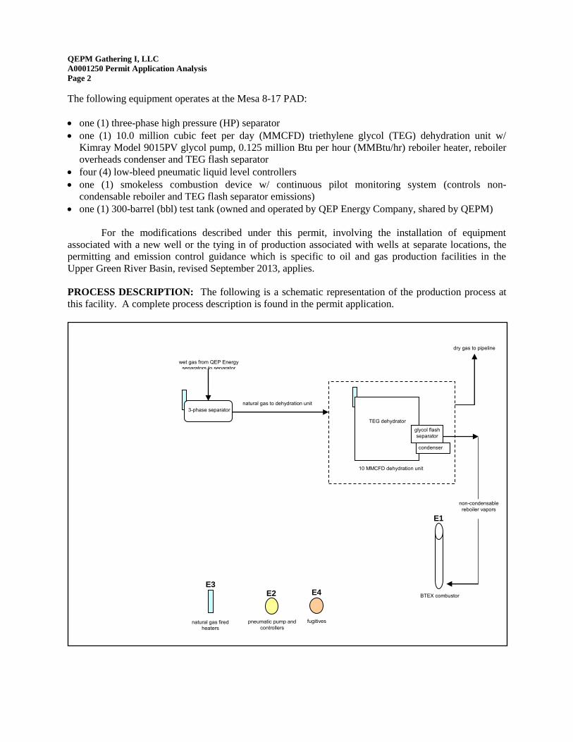
PROCESS DESCRIPTION: The following is a schematic representation of the production process at
this facility. A complete process description is found in the permit application.
natural gas fired heaters
pneumatic pump and
controllers
BTEX combustor
E1
TEG dehydrator
E3
wet gas from QEP Energy separators to separator
glycol flash
separator
non-condensable
reboiler vapors
3-phase separator
dry gas to pipeline
E2 E4
fugitives
10 MMCFD dehydration unit
natural gas to dehydration unit
condenser
QEPM Gathering I, LLC
A0001250 Permit Application Analysis
Page 3
ESTIMATED EMISSIONS: (summarized in the attached tables)
dehydration unit:
reboiler still vent:
Potential, uncontrolled VOC and HAP emissions are estimated using GRI-GLYCalc V4.0
software based on the hydrocarbon composition of wet gas from the Mesa 8-17 PAD
separator, reported operating parameters, the maximum circulation rate for the Kimray
Model 9015PV glycol pump and the average daily gas production rate reported by the
applicant.
Controlled VOC and HAP emissions (Emission Source E1, Process Flow Diagram)
were estimated in the same fashion except a condenser was added to the reboiler still vent
and a combustion device was added to the non-condensable reboiler still vent stream.
The condenser is proposed to operate at 100ºF and 12 psia. The combustion device is
reported to have 98% destruction efficiency. NOX and CO emissions from the
combustion of non-condensable reboiler and TEG flash separator vapors are based on
0.14 lb NOX/MMBtu and 0.035 lb CO/MMBtu and the estimated volume of vapors.
pneumatic pump and controllers: (Emission Source E2, Process Flow Diagram)
Uncontrolled emissions from pneumatic controllers are based on the manufacturer’s
bleed rate for each controller, the VOC and HAP content of the gas used and 8760 annual
operating hours.
Emissions from the pneumatic liquid level controllers are vented to the atmosphere.
natural gas fired heaters: (Emission Source E3, Process Flow Diagram)
NOX and CO emissions are based on AP-42 EF for fuel boilers and heaters.
fugitive sources: (Emission Source E4, Process Flow Diagram)
QEPM Gathering I, LLC is implementing a leak detection and repair (LDAR) program at
this facility to minimize fugitive leaks. Based on previous inspection results and with the
implementation of the LDAR program, VOC and HAP emissions associated with fugitive
leaks are considered insignificant.
BEST AVAILABLE CONTROL TECHNOLOGY (BACT): The following table summarizes
Presumptive BACT notice and control installation requirements under the 2013 Chapter 6, Section 2 Oil
and Gas Production Facilities Permitting Guidance (C6 S2 Guidance).
Application, Emissions Controls,
Monitoring Date Due Date Filed/Installed
Application 7/7/2015
(within 60-days of modification) 7/7/2015
Dehy Emissions Control 5/7/2015
(upon modification) 8/19/2008
Continuous Monitoring 5/7/2015
(upon modification) 8/19/2008
No/Low-Bleed Pneumatic Controllers 5/7/2015
(upon modification) 11/6/2010 and 10/26/2011
QEPM Gathering I, LLC
A0001250 Permit Application Analysis
Page 4
The emissions control, reporting and monitoring requirements under the 2013 C6 S2 Guidance
have been met.
Periodic site evaluations of air pollution control equipment, institution of annual equipment
maintenance programs and operator training on the proper operation of pollution control equipment have
been incorporated in the conditions of this permit to ensure effective operation of the pollution control
equipment installed to meet the BACT requirements of the 2013 C6 S2 Guidance.
NEW SOURCE PERFORMANCE STANDARDS (NSPS): There are no condensate tanks located at
the Mesa 8-17 PAD; therefore, Subpart K, Ka and Kb does not apply.
40 CFR part 60, subpart OOOO - Standards of Performance for Crude Oil and Natural Gas Production,
Transmission and Distribution applies to any new, modified or reconstructed emission source installed
after August 23, 2011 at oil and gas production and gas processing facilities. The Mesa 8-17 PAD is not
subject to 40 CFR part 60, subpart OOOO as the facility was constructed prior to the effective date.
PREVENTION OF SIGNIFICANT DETERIORATION (PSD): Emissions from this facility are less
than the major source levels defined in WAQSR Chapter 6, Section 4.
CHAPTER 6, SECTION 3 (Operating Permit): Emissions from this facility are less than the major
source levels defined in WAQSR Chapter 6, Section 3.
NATIONAL EMISSION STANDARDS FOR HAZARDOUS AIR POLLUTANTS (MACT): Emissions from this facility are less than the major source levels of 10 TPY of any individual HAP and 25
TPY of any combination of HAPs; therefore this facility is not subject to 40 CFR part 63, subpart HH
requirements for oil and gas production facilities which are major sources of HAP emissions.
QEPM Gathering I, LLC operates glycol dehydration unit(s) which are affected area sources under 40
CFR part 63, subpart HH. Based on the information in the application, the glycol dehydration unit(s) are
exempt from the control requirements of 40 CFR part 63, subpart HH for glycol dehydration units
because the actual annual average flowrate of natural gas to the glycol dehydration unit is less than 85
thousand standard cubic meters (3.0 MMSCFD) or the actual average emissions of benzene from the
glycol dehydration unit process vent to the atmosphere are less than 0.90 megagrams per year (1.0 tons
per year). QEPM Gathering I, LLC shall maintain records of the actual annual average flowrate of
natural gas to the glycol dehydration unit or actual average emissions of benzene from the glycol
dehydration unit process vent for each year of operation in accordance with 63.774(d)(1). The procedures
in 63.772(b) shall be used to determine the glycol dehydration unit flowrate or benzene emissions.
QEPM Gathering I, LLC shall comply with all applicable requirements of 40 CFR part 63, subpart HH.
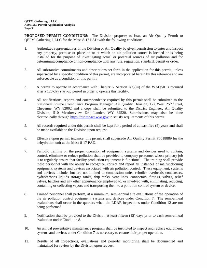
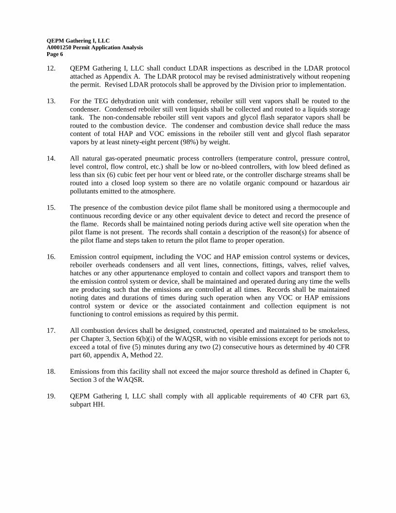
12. QEPM Gathering I, LLC shall conduct LDAR inspections as described in the LDAR protocol
attached as Appendix A. The LDAR protocol may be revised administratively without reopening
the permit. Revised LDAR protocols shall be approved by the Division prior to implementation.
13. For the TEG dehydration unit with condenser, reboiler still vent vapors shall be routed to the
condenser. Condensed reboiler still vent liquids shall be collected and routed to a liquids storage
tank. The non-condensable reboiler still vent vapors and glycol flash separator vapors shall be
routed to the combustion device. The condenser and combustion device shall reduce the mass
content of total HAP and VOC emissions in the reboiler still vent and glycol flash separator
vapors by at least ninety-eight percent (98%) by weight.
14. All natural gas-operated pneumatic process controllers (temperature control, pressure control,
level control, flow control, etc.) shall be low or no-bleed controllers, with low bleed defined as
less than six (6) cubic feet per hour vent or bleed rate, or the controller discharge streams shall be
routed into a closed loop system so there are no volatile organic compound or hazardous air
pollutants emitted to the atmosphere.
15. The presence of the combustion device pilot flame shall be monitored using a thermocouple and
continuous recording device or any other equivalent device to detect and record the presence of
the flame. Records shall be maintained noting periods during active well site operation when the
pilot flame is not present. The records shall contain a description of the reason(s) for absence of
the pilot flame and steps taken to return the pilot flame to proper operation.
16. Emission control equipment, including the VOC and HAP emission control systems or devices,
reboiler overheads condensers and all vent lines, connections, fittings, valves, relief valves,
hatches or any other appurtenance employed to contain and collect vapors and transport them to
the emission control system or device, shall be maintained and operated during any time the wells
are producing such that the emissions are controlled at all times. Records shall be maintained
noting dates and durations of times during such operation when any VOC or HAP emissions
control system or device or the associated containment and collection equipment is not
functioning to control emissions as required by this permit.
17. All combustion devices shall be designed, constructed, operated and maintained to be smokeless,
per Chapter 3, Section 6(b)(i) of the WAQSR, with no visible emissions except for periods not to
exceed a total of five (5) minutes during any two (2) consecutive hours as determined by 40 CFR
part 60, appendix A, Method 22.
18. Emissions from this facility shall not exceed the major source threshold as defined in Chapter 6,
Section 3 of the WAQSR.
19. QEPM Gathering I, LLC shall comply with all applicable requirements of 40 CFR part 63,
subpart HH.
QEPM Gathering I, LLC
A0001250 Permit Application Analysis
Page 7
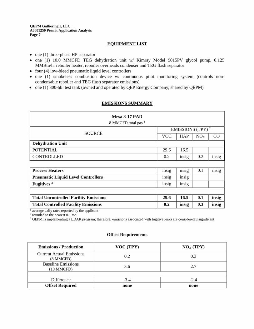
EQUIPMENT LIST
one (1) three-phase HP separator
one (1) 10.0 MMCFD TEG dehydration unit w/ Kimray Model 9015PV glycol pump, 0.125
MMBtu/hr reboiler heater, reboiler overheads condenser and TEG flash separator
four (4) low-bleed pneumatic liquid level controllers
one (1) smokeless combustion device w/ continuous pilot monitoring system (controls non-
condensable reboiler and TEG flash separator emissions)
one (1) 300-bbl test tank (owned and operated by QEP Energy Company, shared by QEPM)
EMISSIONS SUMMARY
Mesa 8-17 PAD
8 MMCFD total gas 1
SOURCE EMISSIONS (TPY) 2
VOC HAP NOX CO
Dehydration Unit
POTENTIAL 29.6 16.5
CONTROLLED 0.2 insig 0.2 insig
Process Heaters insig insig 0.1 insig
Pneumatic Liquid Level Controllers insig insig
Fugitives 3 insig insig
Total Uncontrolled Facility Emissions 29.6 16.5 0.1 insig
Total Controlled Facility Emissions 0.2 insig 0.3 insig 1 average daily rates reported by the applicant 2 rounded to the nearest 0.1 ton 3 QEPM is implementing a LDAR program; therefore, emissions associated with fugitive leaks are considered insignificant
Offset Requirements
Emissions / Production VOC (TPY) NOX (TPY)
Current Actual Emissions (8 MMCFD)
0.2 0.3
Baseline Emissions (10 MMCFD)
3.6 2.7
Difference -3.4 -2.4
Offset Required none none
Appendix A
LDAR Protocol
QEP ENERGY COMPANY’S Leak Detection and Repair Program
1 | P a g e
Facility Fugitive Emission Monitoring In order to demonstrate and formally document the effectiveness of the efforts made to minimize emissions
from fugitive component leaks, QEP Energy Company (QEP) has committed to monitoring and fixing leaks at
their larger exploration and production facilities on the Pinedale Anticline through the implementation of a
formal Leak Detection and Repair (LDAR) Program. The components and schedule of this program are
described in the plan that follows. A brief outline of the documents in this binder is provided below.
1. Program Outline
a. Basis
b. Facility Identification
c. Schedule
d. Technology
e. Leak Repair Schedule
f. Recordkeeping & Documentation
2. Inspection Protocol
a. OnSite Procedure
b. Sensitivity Check Procedure
c. Followup Procedure
3. Monitoring Documentation
a. LDAR Summary Spreadsheet
b. CD containing:
i. Facility List
ii. LDAR Findings by Tag Number Spreadsheet
iii. Surveillance and Repair Forms
iv. Sensitivity Check Documentation
c. DVD containing:
i. IR Camera Video Documentation
4. Example Forms
a. Field Surveillance Form – Example
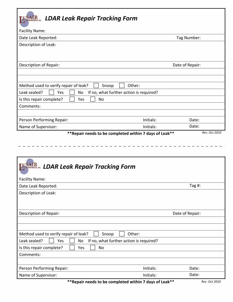
b. Leak Repair Tracking Form – Example
c. Sensitivity Check Form – Example
QEP ENERGY COMPANY’S Leak Detection and Repair Program
2 | P a g e
1. Program Outline
1.a. Basis:
QEP applies good operating practices (visual and olfactory detection, use of leak detection solutions (e.g.
Snoop), and periodic monitoring with a gas detector) to identify and repair fugitive emissions from
equipment leaks on an on‐going basis at all of its facilities in the Pinedale Anticline Development Area
(PAPA). In order to demonstrate and document the effectiveness of operating procedures that minimize
emissions from equipment leaks, QEP has implemented a formal LDAR program above and beyond current
operating practices. This LDAR program uses an additional monitoring methodology (Infrared Camera) to
identify fugitive VOC emissions from equipment leaks. While the magnitude of the leak cannot be
measured using the infrared camera methodology, the protocol being followed includes the documentation
and repair of any leak detected using the infrared technology. Use of this monitoring approach allows QEP
to demonstrate that its operating practices effectively control fugitive emissions from equipment leaks to
insignificant levels.
1.b. Facility Identification:
While QEP implements good operating practices at all of its facilities in the PAPA, the only facilities included
in QEP’s LDAR program will be those identified in a condition of the associated air quality permit. These
facilities have been identified as having potential emissions above the Wyoming Air Quality Division Best
Available Control Technology (BACT) threshold of 15 TPY per WAQD Oil and Gas Production Facilities
Chapter 6, Section 2 Permitting Guidance, dated 08/2007 or 8 TPY for new and modified facilities after
August 1, 2010 per WAQD Guidance dated 03/2010.
1.c. Schedule:
On a semi‐annual basis, during the 2nd and 4th quarters of every year, production equipment at the
facilities will be monitored following the procedure listed in the ‘Inspection Protocol’ section of this Plan.
Wellhead monitoring will be conducted annually during the 4th quarter inspection.
Modified and newly constructed facilities that are identified in a permit condition as requiring participation
in the LDAR program will be inspected; any leaks will be documented; and applicable repair procedures will
be followed. These facilities will be included in the LDAR program no later than the next semi‐annual
inspection period (see example 1 provided below).
Example 1:
Should the semi‐annual LDAR monitoring occur in May (2nd quarter of the year) and a new facility
begins producing the following June. The emissions for all sources at this facility will be reviewed as per
the WAQD’s Chapter 6 Section 2 Permitting Guidance and an application submitted prior to the 60 day
deadline. For the new facility that began operating in June the fugitive emissions would be reviewed in
August. If at that time the fugitive emissions are projected to exceed the 8 TPY VOC threshold this
facility will be added to the list of facilities to monitor during the next scheduled semi‐annual inspection
(4th quarter of the year).
QEP ENERGY COMPANY’S Leak Detection and Repair Program
3 | P a g e
1.d. Technology:
LDAR inspections will be conducted using infrared (IR) cameras. IR cameras detect the band of light in the
electromagnetic spectrum that extends beyond visible light. Using an IR camera one can identify
hydrocarbon vapors which indicate possible sources of fugitive leaks. It should be noted that the intent of
this device is solely qualitative; it is unable to quantify the magnitude of a leak (i.e., the leak rate). However,
the objective of this program is to identify and repair any observed leak regardless of its magnitude. As
such, the infrared camera is the ideal tool to identify these leaks. It should also be noted that all images
seen through the infrared camera are not necessarily VOC emissions. It can be difficult to determine
whether recordings indicate hydrocarbon vapors or whether the vapors are heat or water vapors. Though,
hydrocarbon vapors should typically dissipate slower and “trail‐off” longer than heat or water vapors. The
design of the camera only allows for detection of vapors and heat emissions and as such the nature of the
emissions is not definitive.
In addition to allowing the visual inspection of equipment for fugitive leaks, the IR camera is also able to
record the images seen to an electronic file. During the course of these inspections, all leaks and potential
VOC emissions are recorded and the recordings are then retained as a part of the documentation of the
inspection.
1.e. Leak Repair Schedule:
Leaks identified through the semi‐annual inspections will be tagged using a numbered weather resistant
tag, documented on a ‘Field Inspection’ form, and a video recording of what was observed will be made and
retained on file. Additionally still photographs of the location of the leak may be taken to assist field
personnel in identifying leaking components. All findings (leaks) identified during an inspection with the
infrared camera will be communicated to field personnel so that they may be repaired.
The most common leak types identified during infrared inspections are associated with loose fittings,
connections and bad seals. These are relatively simple to repair and typically do not require the facility to
be shut down. Though QEP will be diligent about trying to repair every leak in a timely fashion, a delayed
repair schedule will be required in instances where the facility must be shut down or additional time is
required to procure parts or equipment in order to repair a leak. For every leak the following schedule
should be followed to repair leaks identified with the infrared camera.
Repair Attempt Timing
1st Attempt A 1st attempt to repair a leak will be made within 7‐days. This will consist of typical basic repairs (i.e., tightening packing, tightening tubing ferrels). After a repair attempt has been made, verification that the leak has been repaired shall consist of observing the component using an IR camera, Sensit Detector (or similar gas detector), or Snoop (or similar leak detection solutions). Otherwise, visual and/or olfactory inspections shall be conducted to ensure the leak has been repaired. The leak tag may only be removed once repair of the leak has been verified using either an Infrared Camera, Sensit Detector, or Snoop.
QEP ENERGY COMPANY’S Leak Detection and Repair Program
4 | P a g e
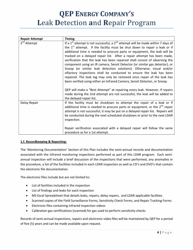
Repair Attempt Timing
2nd Attempt If a 1st attempt is not successful, a 2nd attempt will be made within 7 days of the 1st attempt. If the facility must be shut down to repair a leak or if additional time is needed to procure parts or equipment, the leak will be tracked on a delayed repair list. After a repair attempt has been made, verification that the leak has been repaired shall consist of observing the component using an IR camera, Sensit Detector (or similar gas detector), or Snoop (or similar leak detection solutions). Otherwise, visual and/or olfactory inspections shall be conducted to ensure the leak has been repaired. The leak tag may only be removed once repair of the leak has been verified using either an Infrared Camera, Sensit Detector, or Snoop. QEP will make a “Best Attempt” at repairing every leak. However, if repairs made during the 2nd attempt are not successful, the leak will be added to the delayed repair list.
Delay Repair If the facility must be shutdown to attempt the repair of a leak or if additional time is needed to procure parts or equipment, or the 2nd repair attempt is not successful, it may be put on a delayed repair list. Repairs will be conducted during the next scheduled shutdown or prior to the next LDAR inspection. Repair verification associated with a delayed repair will follow the same procedure as for a 1st attempt.
1.f. Recordkeeping & Reporting:
The ‘Monitoring Documentation’ Section of this Plan includes the semi‐annual records and documentation
associated with the infrared monitoring inspections performed as part of this LDAR program. Each semi‐
annual inspection will include a brief discussion of the inspections that were performed, any anomalies in
the procedure, a list of the facilities included in each LDAR inspection as well as CD’s and DVD’s that contain
the electronic file documentation.
The electronic files include but are not limited to:
List of facilities included in the inspection
List of findings and leaks for each inspection
MS Excel Spreadsheet that details leaks, repairs, delay repairs, and LDAR applicable facilities
Scanned copies of the Field Surveillance Forms, Sensitivity Check Forms, and Repair Tracking Forms
Calibration gas certifications (scanned) for gas used to perform sensitivity checks
Records of semi‐annual inspections, repairs and electronic video files will be maintained by QEP for a period
of five (5) years and can be made available upon request.
QEP ENERGY COMPANY’S Leak Detection and Repair Program
5 | P a g e
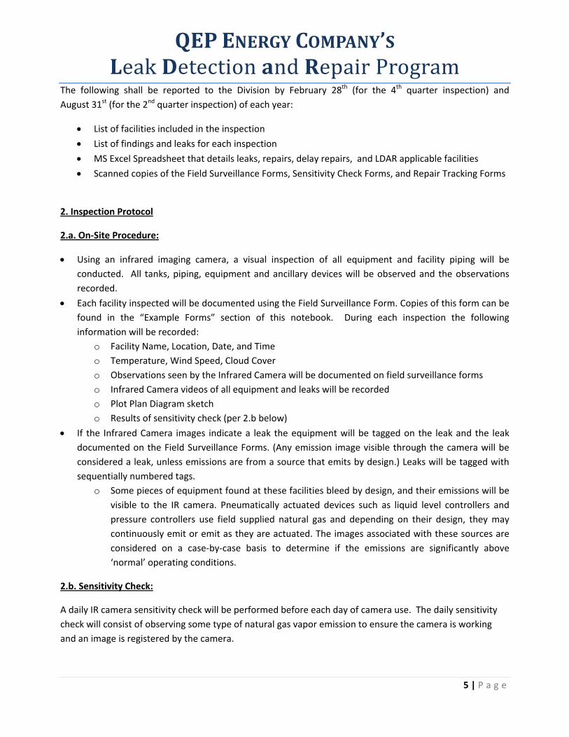
The following shall be reported to the Division by February 28th (for the 4th quarter inspection) and
August 31st (for the 2nd quarter inspection) of each year:
List of facilities included in the inspection
List of findings and leaks for each inspection
MS Excel Spreadsheet that details leaks, repairs, delay repairs, and LDAR applicable facilities
Scanned copies of the Field Surveillance Forms, Sensitivity Check Forms, and Repair Tracking Forms
2. Inspection Protocol
2.a. On‐Site Procedure:
Using an infrared imaging camera, a visual inspection of all equipment and facility piping will be
conducted. All tanks, piping, equipment and ancillary devices will be observed and the observations
recorded.
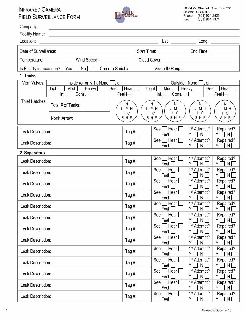
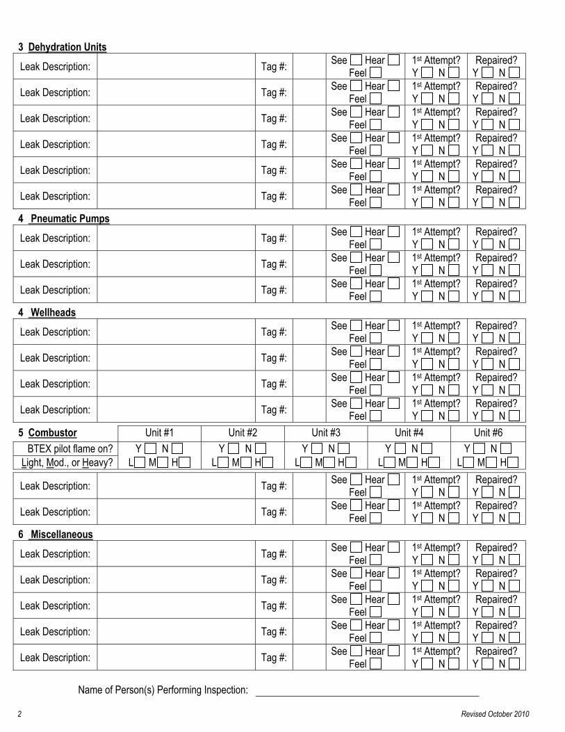
Each facility inspected will be documented using the Field Surveillance Form. Copies of this form can be
found in the “Example Forms” section of this notebook. During each inspection the following
information will be recorded:
o Facility Name, Location, Date, and Time
o Temperature, Wind Speed, Cloud Cover
o Observations seen by the Infrared Camera will be documented on field surveillance forms
o Infrared Camera videos of all equipment and leaks will be recorded
o Plot Plan Diagram sketch
o Results of sensitivity check (per 2.b below)
If the Infrared Camera images indicate a leak the equipment will be tagged on the leak and the leak
documented on the Field Surveillance Forms. (Any emission image visible through the camera will be
considered a leak, unless emissions are from a source that emits by design.) Leaks will be tagged with
sequentially numbered tags.
o Some pieces of equipment found at these facilities bleed by design, and their emissions will be
visible to the IR camera. Pneumatically actuated devices such as liquid level controllers and
pressure controllers use field supplied natural gas and depending on their design, they may
continuously emit or emit as they are actuated. The images associated with these sources are
considered on a case‐by‐case basis to determine if the emissions are significantly above
‘normal’ operating conditions.
2.b. Sensitivity Check:
A daily IR camera sensitivity check will be performed before each day of camera use. The daily sensitivity
check will consist of observing some type of natural gas vapor emission to ensure the camera is working
and an image is registered by the camera.
QEP ENERGY COMPANY’S Leak Detection and Repair Program
6 | P a g e
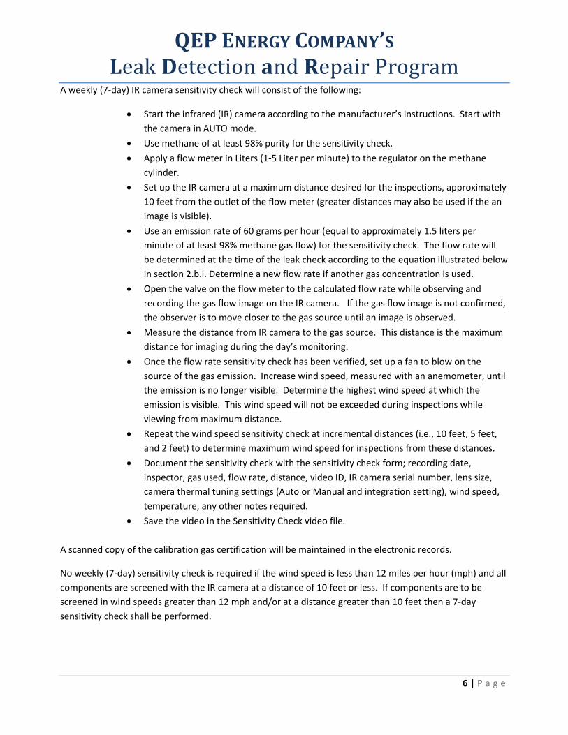
A weekly (7‐day) IR camera sensitivity check will consist of the following:
Start the infrared (IR) camera according to the manufacturer’s instructions. Start with
the camera in AUTO mode. Use methane of at least 98% purity for the sensitivity check. Apply a flow meter in Liters (1‐5 Liter per minute) to the regulator on the methane
cylinder. Set up the IR camera at a maximum distance desired for the inspections, approximately
10 feet from the outlet of the flow meter (greater distances may also be used if the an
image is visible). Use an emission rate of 60 grams per hour (equal to approximately 1.5 liters per
minute of at least 98% methane gas flow) for the sensitivity check. The flow rate will
be determined at the time of the leak check according to the equation illustrated below
in section 2.b.i. Determine a new flow rate if another gas concentration is used. Open the valve on the flow meter to the calculated flow rate while observing and
recording the gas flow image on the IR camera. If the gas flow image is not confirmed,
the observer is to move closer to the gas source until an image is observed. Measure the distance from IR camera to the gas source. This distance is the maximum
distance for imaging during the day’s monitoring. Once the flow rate sensitivity check has been verified, set up a fan to blow on the
source of the gas emission. Increase wind speed, measured with an anemometer, until
the emission is no longer visible. Determine the highest wind speed at which the
emission is visible. This wind speed will not be exceeded during inspections while
viewing from maximum distance. Repeat the wind speed sensitivity check at incremental distances (i.e., 10 feet, 5 feet,
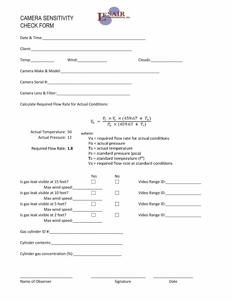
and 2 feet) to determine maximum wind speed for inspections from these distances. Document the sensitivity check with the sensitivity check form; recording date,
inspector, gas used, flow rate, distance, video ID, IR camera serial number, lens size,
camera thermal tuning settings (Auto or Manual and integration setting), wind speed,
temperature, any other notes required. Save the video in the Sensitivity Check video file.
A scanned copy of the calibration gas certification will be maintained in the electronic records.
No weekly (7‐day) sensitivity check is required if the wind speed is less than 12 miles per hour (mph) and all
components are screened with the IR camera at a distance of 10 feet or less. If components are to be
screened in wind speeds greater than 12 mph and/or at a distance greater than 10 feet then a 7‐day
sensitivity check shall be performed.
QEP ENERGY COMPANY’S Leak Detection and Repair Program
7 | P a g e
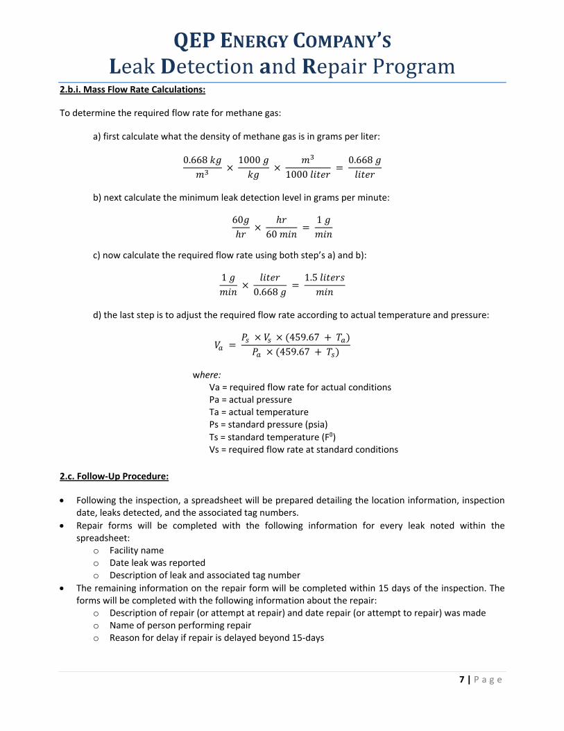
2.b.i. Mass Flow Rate Calculations:
To determine the required flow rate for methane gas:
a) first calculate what the density of methane gas is in grams per liter:
0.668
1000
1000
0.668
b) next calculate the minimum leak detection level in grams per minute:
60
60
1
c) now calculate the required flow rate using both step’s a) and b):
1
0.668
1.5
d) the last step is to adjust the required flow rate according to actual temperature and pressure:
459.67 459.67
where: Va = required flow rate for actual conditions Pa = actual pressure Ta = actual temperature Ps = standard pressure (psia)
Ts = standard temperature (F°) Vs = required flow rate at standard conditions
2.c. Follow‐Up Procedure:
Following the inspection, a spreadsheet will be prepared detailing the location information, inspection date, leaks detected, and the associated tag numbers.
Repair forms will be completed with the following information for every leak noted within the spreadsheet:
o Facility name o Date leak was reported o Description of leak and associated tag number
The remaining information on the repair form will be completed within 15 days of the inspection. The forms will be completed with the following information about the repair:
o Description of repair (or attempt at repair) and date repair (or attempt to repair) was made o Name of person performing repair o Reason for delay if repair is delayed beyond 15‐days
3. Monitoring Documentation
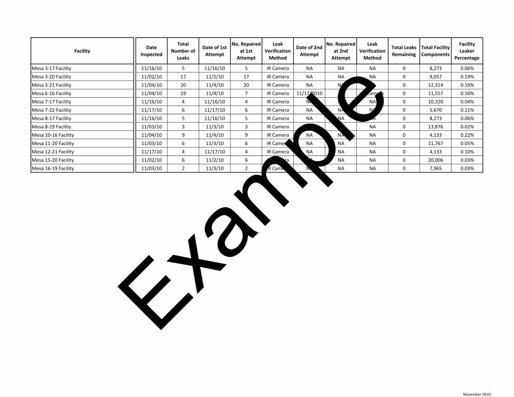
FacilityDate
Inspected
Total
Number of
Leaks
Date of 1st
Attempt
No. Repaired
at 1st
Attempt
Leak
Verification
Method
Date of 2nd
Attempt
No. Repaired
at 2nd
Attempt
Leak
Verification
Method
Total Leaks
Remaining
Total Facility
Components
Facility
Leaker
Percentage
Mesa 3‐17 Facility 11/16/10 5 11/16/10 5 IR Camera NA NA NA 0 8,273 0.06%
Mesa 3‐20 Facility 11/02/10 17 11/2/10 17 IR Camera NA NA NA 0 9,057 0.19%
Mesa 3‐21 Facility 11/04/10 20 11/4/10 20 IR Camera NA NA NA 0 12,314 0.16%
Mesa 6‐16 Facility 11/04/10 19 11/4/10 7 IR Camera 11/17/2010 12 IR Camera 0 11,557 0.16%
Mesa 7‐17 Facility 11/16/10 4 11/16/10 4 IR Camera NA NA NA 0 10,320 0.04%
Mesa 7‐22 Facility 11/17/10 6 11/17/10 6 IR Camera NA NA NA 0 5,670 0.11%
Mesa 8‐17 Facility 11/16/10 5 11/16/10 5 IR Camera NA NA NA 0 8,273 0.06%
Mesa 8‐19 Facility 11/03/10 3 11/3/10 3 IR Camera NA NA NA 0 13,876 0.02%
Mesa 10‐16 Facility 11/04/10 9 11/4/10 9 IR Camera NA NA NA 0 4,133 0.22%
Mesa 11‐20 Facility 11/03/10 6 11/3/10 6 IR Camera NA NA NA 0 11,767 0.05%
Mesa 12‐21 Facility 11/17/10 4 11/17/10 4 IR Camera NA NA NA 0 4,133 0.10%
Mesa 15‐20 Facility 11/02/10 6 11/2/10 6 IR Camera NA NA NA 0 20,006 0.03%
Mesa 16‐19 Facility 11/03/10 2 11/3/10 2 IR Camera NA NA NA 0 7,965 0.03%
November 2010
Exa
mpl
e
Questar Exploration and Production Co. Leak Detection and Repair Program
Facility List, LDAR Findings by Tag Number, &
Surveillance and Repair Forms
Questar Exploration and Production Co. Leak Detection and Repair Program
Infrared Camera Videos
Exa
mple
4. Example Forms
INFRARED CAMERA FIELD SURVEILLANCE FORM
1 Revised October 2010
10354 W. Chatfield Ave., Ste. 200 Littleton, CO 80127 Phone: (303) 904-2525 Fax: (303) 904-7374
Company: Facility Name: Location: Lat: Long: Date of Surveillance: Start Time: End Time:
Temperature: Wind Speed: Cloud Cover:
Is Facility in operation? Yes No Camera Serial #: Video ID Range: 1 Tanks
Vent Valves: Inside (or only 1): None ; or: Outside: None ; or: Light Mod. Heavy
Int. Cons. See Hear
Feel Light Mod. Heavy
Int. Cons. See Hear
Feel Thief Hatches:
Total # of Tanks:
North Arrow:
Leak Description: Tag #: See Hear
Feel 1st Attempt? Y N
Repaired? Y N
Leak Description: Tag #: See Hear Feel
1st Attempt? Y N
Repaired? Y N
2 Separators
Leak Description: Tag #: See Hear Feel
1st Attempt? Y N
Repaired? Y N
Leak Description: Tag #: See Hear Feel
1st Attempt? Y N
Repaired? Y N
Leak Description: Tag #: See Hear Feel
1st Attempt? Y N
Repaired? Y N
Leak Description: Tag #: See Hear Feel
1st Attempt? Y N
Repaired? Y N
Leak Description: Tag #: See Hear Feel
1st Attempt? Y N
Repaired? Y N
Leak Description: Tag #: See Hear Feel
1st Attempt? Y N
Repaired? Y N
Leak Description: Tag #: See Hear Feel
1st Attempt? Y N
Repaired? Y N
Leak Description: Tag #: See Hear Feel
1st Attempt? Y N
Repaired? Y N
Leak Description: Tag #: See Hear Feel
1st Attempt? Y N
Repaired? Y N
Leak Description: Tag #: See Hear Feel
1st Attempt? Y N
Repaired? Y N
Leak Description: Tag #: See Hear Feel
1st Attempt? Y N
Repaired? Y N
Leak Description: Tag #: See Hear Feel
1st Attempt? Y N
Repaired? Y N
Leak Description: Tag #: See Hear Feel
1st Attempt? Y N
Repaired? Y N
N
L M H I C
S H F
N
L M H I C
S H F
N
L M H I C
S H F
N
L M H I C
S H F
N
L M H I C
S H F
3 Dehydration Units
Leak Description: Tag #: See Hear Feel
1st Attempt? Y N
Repaired? Y N
Leak Description: Tag #: See Hear Feel
1st Attempt? Y N
Repaired? Y N
Leak Description: Tag #: See Hear Feel
1st Attempt? Y N
Repaired? Y N
Leak Description: Tag #: See Hear Feel
1st Attempt? Y N
Repaired? Y N
Leak Description: Tag #: See Hear Feel
1st Attempt? Y N
Repaired? Y N
Leak Description: Tag #: See Hear Feel
1st Attempt? Y N
Repaired? Y N
4 Pneumatic Pumps Leak Description: Tag #: See Hear
Feel 1st Attempt? Y N
Repaired? Y N
Leak Description: Tag #: See Hear Feel
1st Attempt? Y N
Repaired? Y N
Leak Description: Tag #: See Hear Feel
1st Attempt? Y N
Repaired? Y N
4 Wellheads Leak Description: Tag #: See Hear
Feel 1st Attempt? Y N
Repaired? Y N
Leak Description: Tag #: See Hear Feel
1st Attempt? Y N
Repaired? Y N
Leak Description: Tag #: See Hear Feel
1st Attempt? Y N
Repaired? Y N
Leak Description: Tag #: See Hear Feel
1st Attempt? Y N
Repaired? Y N
5 Combustor Unit #1 Unit #2 Unit #3 Unit #4 Unit #6 BTEX pilot flame on? Y N Y N Y N Y N Y N
Light, Mod., or Heavy? L M H L M H L M H L M H L M H Leak Description: Tag #: See Hear
Feel 1st Attempt? Y N
Repaired? Y N
Leak Description: Tag #: See Hear Feel
1st Attempt? Y N
Repaired? Y N
6 Miscellaneous
Leak Description: Tag #: See Hear Feel
1st Attempt? Y N
Repaired? Y N
Leak Description: Tag #: See Hear Feel
1st Attempt? Y N
Repaired? Y N
Leak Description: Tag #: See Hear Feel
1st Attempt? Y N
Repaired? Y N
Leak Description: Tag #: See Hear Feel
1st Attempt? Y N
Repaired? Y N
Leak Description: Tag #: See Hear Feel
1st Attempt? Y N
Repaired? Y N
Name of Person(s) Performing Inspection:
2 Revised October 2010
Flow
CAMERA SENSITIVITY CHECK FORM
Date & Time:_________________________________________________