66
AURORA’S TECHNOLOGICAL & RESEARCH INSTITUTE UPPAL, HYDERABAD- 500098 FLUID MECHANICS AND HYDRAULIC MACHINERY LABORATORY MANUAL DEPARTMENT OF MECHANICAL ENGINEERING
AURORA’S TECHNOLOGICAL & RESEARCH INSTITUTE
UPPAL, HYDERABAD- 500098
FLUID MECHANICS AND HYDRAULIC MACHINERY
LABORATORY MANUAL
DEPARTMENT OF
MECHANICAL ENGINEERING
2
PREFACE
The problems, man encountered in the fields of water supply, irrigation, navigation and
water power resulted in the development of Fluid Mechanics. Some two hundred years ago man
kind’s centuries of experience with the flow of water began to crystallize in scientific form. Two distinct schools of thought gradually evolved in the treatment of fluid mechanics. One,
commonly known as Classical Hydrodynamics, deals with theoretical aspect of the fluid flow,
which assumes that shearing stresses are non-existent in the fluids, that is ideal fluid concept.
The other known as Hydraulics, deals with the practical aspects of fluid flow which has been
developed from experimental findings and is therefore, more of empirical nature.
These lab sessions are intended to make the students understand the different methods of
flow rates in pipe flow and open channel flows, conversion of hydraulic energy possessed by the
water in running turbines and how pumps are used to increase the hydraulic energy of the water
etc.
3
LAB CODE
1. Students should report to the concerned labs as per the timetable schedule.
2. Students who turn up late to the labs will in no case to be permitted to perform the
experiment scheduled for the day.
3. After completion of the experiment, certification of the concerned staff in-charge in
the observation book is necessary.
4. Students should bring a note book of about 100 pages and should enter the
readings / observations into the note book while performing the experiment.
5. The record of observations along with the detailed experimental procedure of the
experiment performed in the immediate last session should be submitted and certified
by the staff member in-charge.
6. Not more than three students in a group are permitted to perform the experiment on a
setup.
7. The group-wise division made in the beginning should be adhered to, and no mix up
of student among different groups will be permitted later.
8. The components required pertaining to the experiment should be collected from
stores in-charges after duly filling in the requisition form.
9. When the experiment is completed, students should disconnect the setup made
by them, and should return all the components/instruments taken for the
purpose.
10. Any damage of the equipment is completed, students should disconnect the setup
made by them, and should return all the components/instruments taken for the
purpose.]
11. Students should be present in the labs for the total scheduled duration.
12. Students are required to prepare thoroughly to perform the experiment before coming
to Laboratory.
13. Procedure sheets/data sheets provided to the students’ groups should be maintained neatly and to be returned after the experiment.
4
CONTENTS
S.No. Name of the Experiment Page No.
1. IMPACT OF JET ON VANES 5-8
2. PELTON WHEEL 9-17
3. FRANCIS TURBINE 18-26
4. KAPLAN TURBINE 27-36
5. RECIPROCATING PUMP 37-42
6. CENTRIFUGAL PUMP 43-48
7. VENTURI METER 49-53
8. ORIFICE METER 54-59
9. NOTCH APPARATUS 60-63
10. VERIFICATION OF BERNOULLIS THEOREM 64-66
5
Experiment No. 1
IMPACT OF JET ON VANES
Aim:
To determine the of co-efficient of impact of jet on vane by comparing the actual force
with the theoretical force for stationary vanes of different shapes viz. Hemi-spherical , Flat plate
and inclined plate .
Apparatus Required:
1. Impact of jet apparatus with rotameter.
2. Flat and inclined plates, and hemispherical vanes.
3. Force indicator balance.
Specifications: Vane shapes : Flat , Hemispherical, Inclined (standard)
Jets Dia. : 4 mm
Max. Jet Force : 1 kgf
Measurements : a) Flow rate of water by direct reading rotameter.
b) Pressure of jet by pressure gauge.
c) Jet force by direct reading analog force indicator.
Pump : 1hp , 1ph , 230V , with starter.
Type : Re-circulating with sump and jet chamber made of stainless steel.
Jet Chamber : Fixed with toughened glass windows with leak proof Rubber
gaskets.
Theory:
When the jet of water is directed to hit the vane of any particular shape, the force is
exerted on it by the fluid. This force large in magnitude acting for a short duration is termed as
impact force. The magnitude of the force exerted on the plate/vane depends on the speed of jet,
shape of vane, fluid density and flow rate of water. More importantly, it also depends on whether
the vane is moving or stationary. In our present case, we are concerned about the force exerted
on the stationary plates/vanes. The following are the theoretical formulae for different shapes of
vane, based on flow rate .
1) Hemi – Spherical:
Ft = ( 2 ρ A V2/ g)
6
2) Flat Plate :
Ft = ( ρ A V2/ g)
3) Inclined Plate:
Ft = ( ρ A V2/ g) Sin
2
Where
‘g’ = 9.81 m/sec2
‘A’ = Area of jet in m2
‘ρ’ = Density of water = 1000 kg / m2
‘V’ = Velocity of jet in m/sec
‘ ’ = Angle made by the axis of jet with the inclined plate (60o)
‘Ft’ = The theoretical force acting parallel to the direction of jet. ‘Fa’ = Actual force developed as indicated by the analog force indicator.
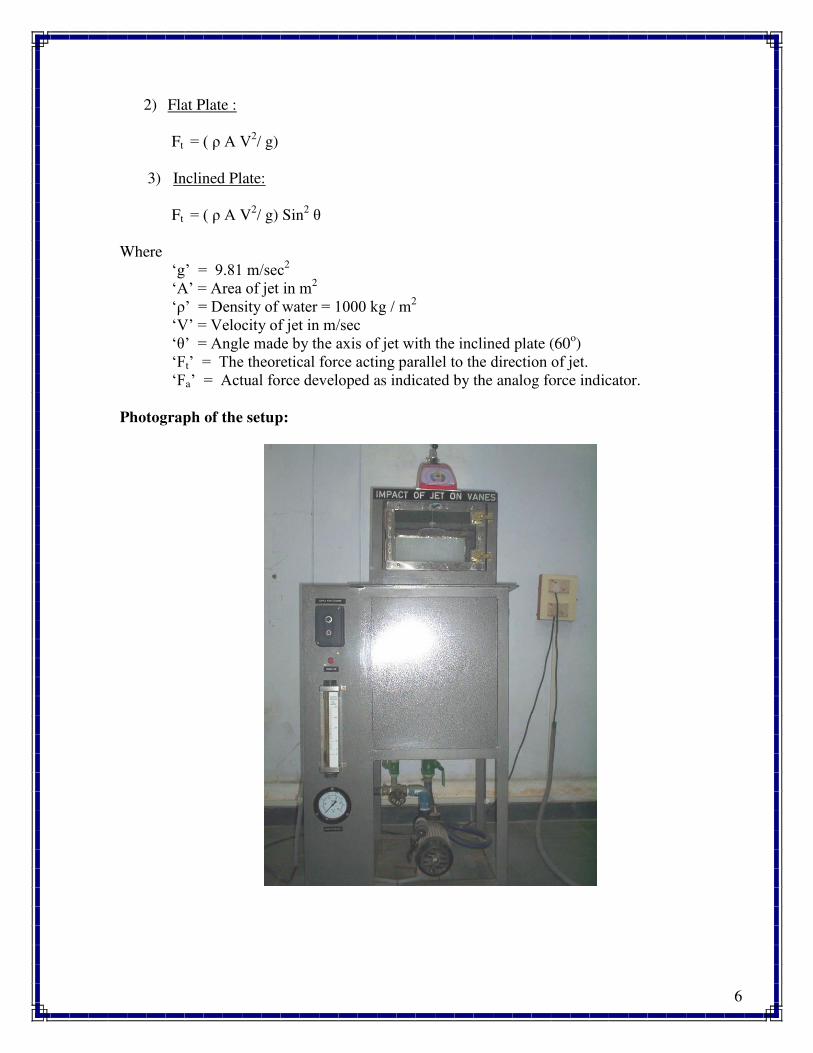
Photograph of the setup:
7
Procedure:
1) Fix the required diameter jet, and the vane of required shape in position.
2) Set the force indicator to zero.
3) Keep the delivery valve closed and switch on the pump.
4) Close the front transparent cover tightly.
5) Open the delivery valve and adjust the flow rate of water as read on the
rotameter.
6) Observe the force as indicated on force indicator.
7) Note down the diameter of jet, shape of vane, flow rate and force and tabulate the
readings for five different flow rates.
8) Repeat the experiment for the other vanes.
9) Switch off the pump after the experiment is over and close the delivery valve.
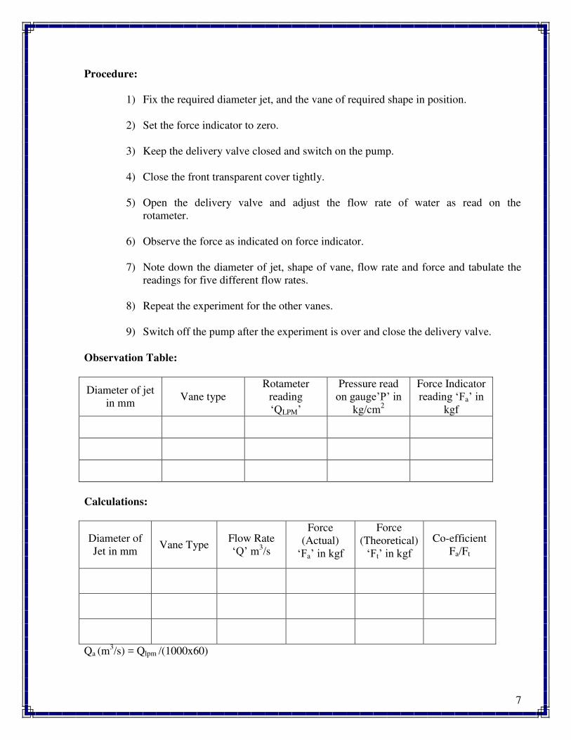
Observation Table:
Diameter of jet
in mm Vane type
Rotameter
reading
‘QLPM’
Pressure read
on gauge’P’ in kg/cm
2
Force Indicator
reading ‘Fa’ in kgf
Calculations:
Diameter of
Jet in mm Vane Type
Flow Rate
‘Q’ m3/s
Force
(Actual)
‘Fa’ in kgf
Force
(Theoretical)
‘Ft’ in kgf Co-efficient
Fa/Ft
Qa (m3/s) = Qlpm /(1000x60)
8
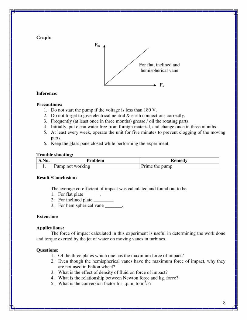
Graph:
Inference:
Precautions:
1. Do not start the pump if the voltage is less than 180 V.
2. Do not forget to give electrical neutral & earth connections correctly.
3. Frequently (at least once in three months) grease / oil the rotating parts.
4. Initially, put clean water free from foreign material, and change once in three months.
5. At least every week, operate the unit for five minutes to prevent clogging of the moving
parts.
6. Keep the glass pane closed while performing the experiment.
Trouble shooting:
S.No. Problem Remedy
1. Pump not working Prime the pump
Result /Conclusion:
The average co-efficient of impact was calculated and found out to be
1. For flat plate_______.
2. For inclined plate ________.
3. For hemispherical vane _______.
Extension:
Applications:
The force of impact calculated in this experiment is useful in determining the work done
and torque exerted by the jet of water on moving vanes in turbines.
Questions:
1. Of the three plates which one has the maximum force of impact?
2. Even though the hemispherical vanes have the maximum force of impact, why they
are not used in Pelton wheel?
3. What is the effect of density of fluid on force of impact?
4. What is the relationship between Newton force and kg. force?
5. What is the conversion factor for l.p.m. to m3/s?
Fth
Fa
For flat, inclined and
hemispherical vane
9
Experiment No. 2
PELTON WHEEL TURBINE
Aim:
To determine the performance characteristics of Pelton wheel turbine under constant head
and constant speed.
Apparatus Required:
Pelton wheel turbine test rig.
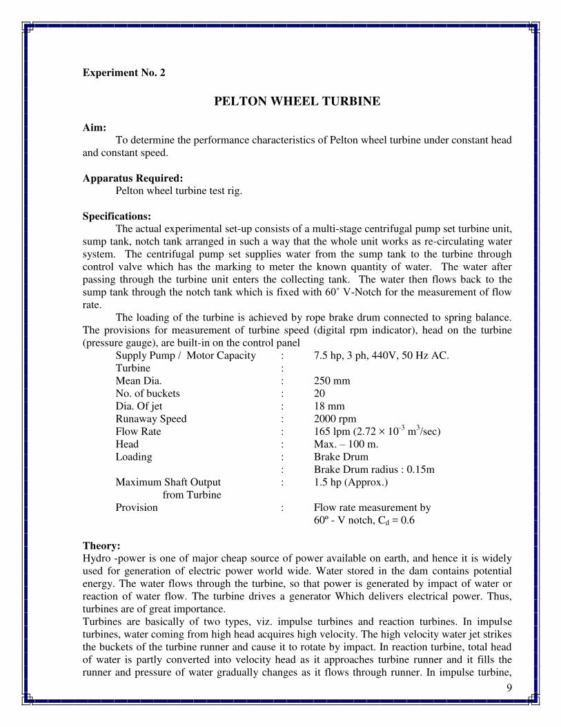
Specifications:
The actual experimental set-up consists of a multi-stage centrifugal pump set turbine unit,
sump tank, notch tank arranged in such a way that the whole unit works as re-circulating water
system. The centrifugal pump set supplies water from the sump tank to the turbine through
control valve which has the marking to meter the known quantity of water. The water after
passing through the turbine unit enters the collecting tank. The water then flows back to the
sump tank through the notch tank which is fixed with θ0˚ V-Notch for the measurement of flow
rate.
The loading of the turbine is achieved by rope brake drum connected to spring balance.
The provisions for measurement of turbine speed (digital rpm indicator), head on the turbine
(pressure gauge), are built-in on the control panel
Supply Pump / Motor Capacity : 7.5 hp, 3 ph, 440V, 50 Hz AC.
Turbine :
Mean Dia. : 250 mm
No. of buckets : 20
Dia. Of jet : 18 mm
Runaway Speed : 2000 rpm
Flow Rate : 165 lpm (2.72 × 10⁻³
m3/sec)
Head : Max. – 100 m.
Loading : Brake Drum
: Brake Drum radius : 0.15m
Maximum Shaft Output : 1.5 hp (Approx.)
from Turbine
Provision : Flow rate measurement by
60º - V notch, Cd = 0.6
Theory:
Hydro -power is one of major cheap source of power available on earth, and hence it is widely
used for generation of electric power world wide. Water stored in the dam contains potential
energy. The water flows through the turbine, so that power is generated by impact of water or
reaction of water flow. The turbine drives a generator Which delivers electrical power. Thus,
turbines are of great importance.
Turbines are basically of two types, viz. impulse turbines and reaction turbines. In impulse
turbines, water coming from high head acquires high velocity. The high velocity water jet strikes
the buckets of the turbine runner and cause it to rotate by impact. In reaction turbine, total head
of water is partly converted into velocity head as it approaches turbine runner and it fills the
runner and pressure of water gradually changes as it flows through runner. In impulse turbine,
10
the only turbine used now-a-days is Pelton Wheel Turbine. In reaction turbines, Francis Turbine
and Kaplan Turbine are the examples.
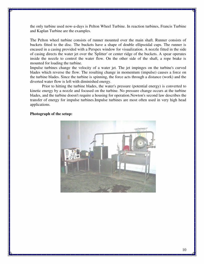
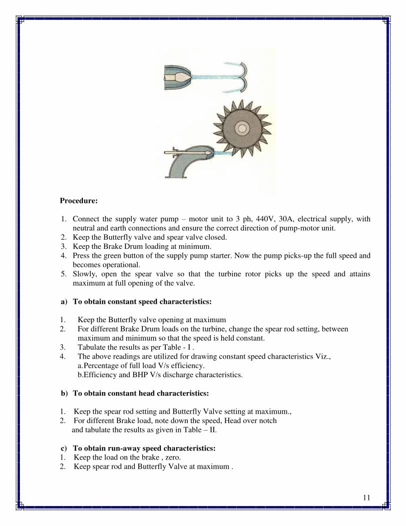
The Pelton wheel turbine consists of runner mounted over the main shaft. Runner consists of
buckets fitted to the disc. The buckets have a shape of double ellipsoidal cups. The runner is
encased in a casing provided with a Perspex window for visualization. A nozzle fitted in the side
of casing directs the water jet over the 'Splitter' or center ridge of the buckets. A spear operates
inside the nozzle to control the water flow. On the other side of the shaft, a rope brake is
mounted for loading the turbine.
Impulse turbines change the velocity of a water jet. The jet impinges on the turbine's curved
blades which reverse the flow. The resulting change in momentum (impulse) causes a force on
the turbine blades. Since the turbine is spinning, the force acts through a distance (work) and the
diverted water flow is left with diminished energy.
Prior to hitting the turbine blades, the water's pressure (potential energy) is converted to
kinetic energy by a nozzle and focused on the turbine. No pressure change occurs at the turbine
blades, and the turbine doesn't require a housing for operation.Newton's second law describes the
transfer of energy for impulse turbines.Impulse turbines are most often used in very high head
applications.
Photograph of the setup:
11
Procedure:
1. Connect the supply water pump – motor unit to 3 ph, 440V, 30A, electrical supply, with
neutral and earth connections and ensure the correct direction of pump-motor unit.
2. Keep the Butterfly valve and spear valve closed.
3. Keep the Brake Drum loading at minimum.
4. Press the green button of the supply pump starter. Now the pump picks-up the full speed and
becomes operational.
5. Slowly, open the spear valve so that the turbine rotor picks up the speed and attains
maximum at full opening of the valve.
a) To obtain constant speed characteristics:
1. Keep the Butterfly valve opening at maximum
2. For different Brake Drum loads on the turbine, change the spear rod setting, between
maximum and minimum so that the speed is held constant.
3. Tabulate the results as per Table - I .
4. The above readings are utilized for drawing constant speed characteristics Viz.,
a. Percentage of full load V/s efficiency.
b.Efficiency and BHP V/s discharge characteristics.
b) To obtain constant head characteristics:
1. Keep the spear rod setting and Butterfly Valve setting at maximum.,
2. For different Brake load, note down the speed, Head over notch
and tabulate the results as given in Table – II.
c) To obtain run-away speed characteristics:
1. Keep the load on the brake , zero.
2. Keep spear rod and Butterfly Valve at maximum .
12
Note:
Run – away speed is also influenced by the tightening in gland packing of the turbine shaft.
More the tightness, less the run – away speed.
d) Performance under unit head – Unit quantities:
In order to predict the behavior of a turbine working under varying conditions and to
facilitate comparison between the performances of the turbines of the same type but having
different outputs and speeds and working under different heads, it is often convenient to express
the test results in terms of certain unit quantities.
From the output of a turbine corresponding to different working heads (Table of
Calculations – II) it is possible to compute the output which would be developed if the head was
reduced to unit (say 1 m..); the speed being adjustable so that the efficiency remains unaffected.
a. Unit Speed, HN/Nu
b. Unit power, 3/2u P/HP
c. Unit Discharge, HQ/Qu
d. Specific Speed,
The specific speed of any turbine is the speed in rpm of a turbine geometrically similar to the
actual turbine but of such a size that under corresponding conditions it will develop 1 metric
horse power when working under unit head (i.e., 1 meter.).
The specific speed is usually computed for the operating conditions corresponding to the
maximum efficiency.
5/4u
H
PNN
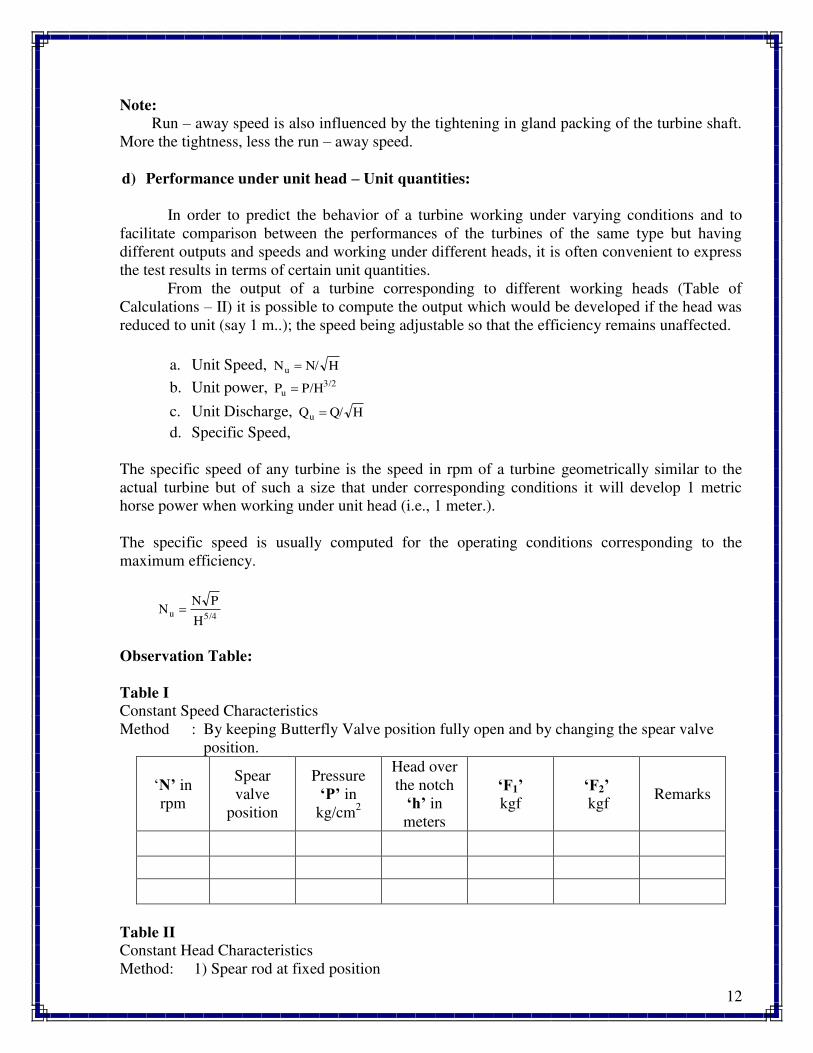
Observation Table:
Table I
Constant Speed Characteristics
Method : By keeping Butterfly Valve position fully open and by changing the spear valve
position.
‘N’ in
rpm
Spear
valve
position
Pressure
‘P’ in
kg/cm2
Head over
the notch
‘h’ in
meters
‘F1’ kgf
‘F2’ kgf
Remarks
Table II
Constant Head Characteristics
Method: 1) Spear rod at fixed position
13
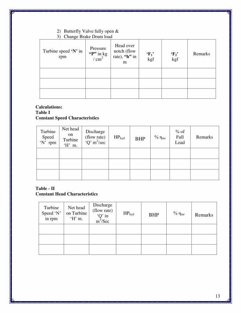
2) Butterfly Valve fully open &
3) Change Brake Drum load
Turbine speed ‘N’ in
rpm
Pressure
“P” in kg
/ cm2
Head over
notch (flow
rate), “h” in
m
‘F1’ kgf
‘F2’ kgf
Remarks
Calculations:
Table I
Constant Speed Characteristics
Turbine
Speed
‘N’ rpm
Net head
on
Turbine
‘H’ m.
Discharge
(flow rate)
‘Q’ m3/sec
HPhyd BHP % tur
% of
Full
Load
Remarks
Table - II
Constant Head Characteristics
Turbine
Speed ‘N’ in rpm
Net head
on Turbine
‘H’ m.
Discharge
(flow rate)
‘Q’ in m
3/Sec
HPhyd BHP % tur Remarks
14
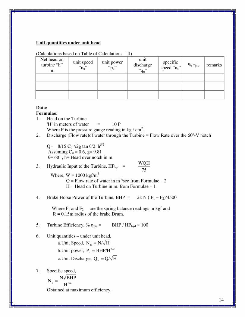
Unit quantities under unit head
(Calculations based on Table of Calculations – II)
Net head on
turbine “h”
m.
unit speed
“nu”
unit power
“pu”
unit
discharge
“qu”
specific
speed “ns” % tur remarks
Data:
Formulae:
1. Head on the Turbine
'H’ in meters of water = 10 P
Where P is the pressure gauge reading in kg / cm2.
2. Discharge (Flow rate)of water through the Turbine = Flow Rate over the 60º-V notch
Q = 8/15 Cd √2g tan /2 h5/2
Assuming Cd = 0.6, g= 9.81
= θ0˚ , h= Head over notch in m.
3. Hydraulic Input to the Turbine, HPhyd = 75
WQH
Where, W = 1000 kgf/m3
Q = Flow rate of water in m3/sec from Formulae – 2
H = Head on Turbine in m. from Formulae – 1
4. Brake Horse Power of the Turbine, BHP = 2π N ( F1 – F2)/4500
Where F1 and F2 are the spring balance readings in kgf and
R = 0.15m radius of the brake Drum.
5. Turbine Efficiency, % tur = BHP / HPhyd × 100
6. Unit quantities – under unit head,
a. Unit Speed, HN/N u
b.Unit power, 3/2
u P/HBHP
c. Unit Discharge, HQ/Qu
7. Specific speed,
5/4u
H
BHPNN
Obtained at maximum efficiency.
15
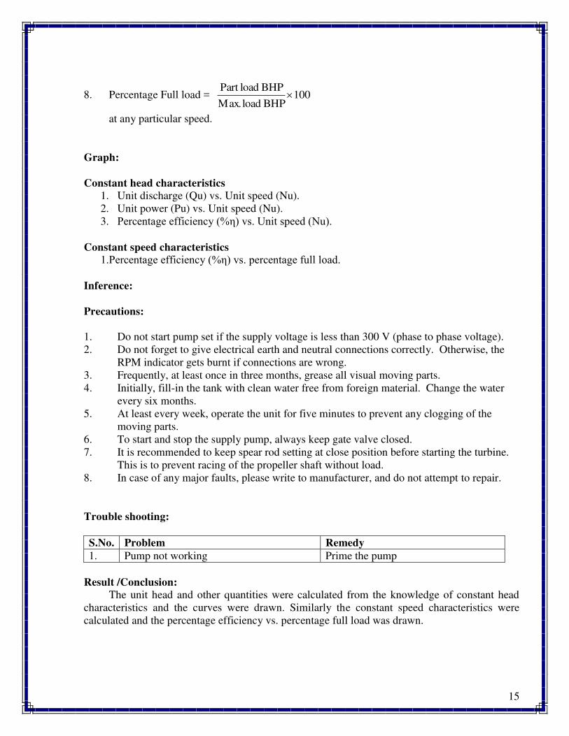
8. Percentage Full load = 100BHPload.Max
BHPloadPart
at any particular speed.
Graph:
Constant head characteristics
1. Unit discharge (Qu) vs. Unit speed (Nu).
2. Unit power (Pu) vs. Unit speed (Nu).
3. Percentage efficiency (% ) vs. Unit speed (Nu).
Constant speed characteristics
1.Percentage efficiency (% ) vs. percentage full load.
Inference:
Precautions:
1. Do not start pump set if the supply voltage is less than 300 V (phase to phase voltage).
2. Do not forget to give electrical earth and neutral connections correctly. Otherwise, the
RPM indicator gets burnt if connections are wrong.
3. Frequently, at least once in three months, grease all visual moving parts.
4. Initially, fill-in the tank with clean water free from foreign material. Change the water
every six months.
5. At least every week, operate the unit for five minutes to prevent any clogging of the
moving parts.
6. To start and stop the supply pump, always keep gate valve closed.
7. It is recommended to keep spear rod setting at close position before starting the turbine.
This is to prevent racing of the propeller shaft without load.
8. In case of any major faults, please write to manufacturer, and do not attempt to repair.
Trouble shooting:
S.No. Problem Remedy
1. Pump not working Prime the pump
Result /Conclusion:
The unit head and other quantities were calculated from the knowledge of constant head
characteristics and the curves were drawn. Similarly the constant speed characteristics were
calculated and the percentage efficiency vs. percentage full load was drawn.
16
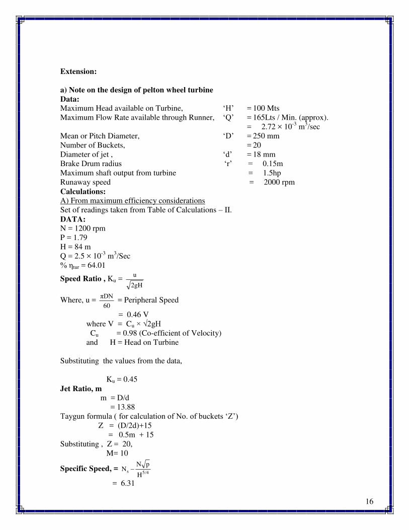
Extension:
a) Note on the design of pelton wheel turbine
Data:
Maximum Head available on Turbine, ‘H’ = 100 Mts
Maximum Flow Rate available through Runner, ‘Q’ = 165Lts / Min. (approx).
= 2.72 × 10⁻³
m3/sec
Mean or Pitch Diameter, ‘D’ = 250 mm
Number of Buckets, = 20
Diameter of jet , ‘d’ = 18 mm
Brake Drum radius ‘r’ = 0.1ηm
Maximum shaft output from turbine = 1.5hp
Runaway speed = 2000 rpm
Calculations:
A) From maximum efficiency considerations
Set of readings taken from Table of Calculations – II.
DATA:
N = 1200 rpm
P = 1.79
H = 84 m
Q = 2.5 × 10⁻³
m3/Sec
% tur = 64.01
Speed Ratio , Ku = 2gH
u
Where, u = 60
πDN = Peripheral Speed
= 0.46 V
where V = Cu × √2gH
Cu = 0.98 (Co-efficient of Velocity)
and H = Head on Turbine
Substituting the values from the data,
Ku = 0.45
Jet Ratio, m
m = D/d
= 13.88
Taygun formula ( for calculation of No. of buckets ‘Z’) Z = (D/2d)+15
= 0.5m + 15
Substituting , Z = 20,
M= 10
Specific Speed, = 5/4s
H
pNN
= 6.31

17
Applications:
Impulse turbines are used in hydro-electric power generation when high head is available in the
reservior .
Questions:
1. On what principle the Pelton wheel turbine works?
2. What is the shape of buckets in Pelton wheel turbine?
3. What is the clearance angle of the buckets? State why it is not 1800?
4. Define unit quantities and specific speed.
5. Why multiple jets are used in Pelton wheel turbine?
18
Experiment No. 3
FRANCIS TURBINE
Aim:
To determine the performance characteristics of Francis turbine under constant head and
constant speed.
Apparatus Required:
Francis turbine test rig.
Specifications: The actual experimental set-up consists of a centrifugal pump set, turbine unit, sump
tank, collecting tank, notch tank arranged in such a way that the whole unit works on re
circulating water system. The centrifugal pump set supplies the water from the sump tank to the
turbine through gate valve. The water after passing through the turbine unit enters the collecting
tank through the draft tube. The water then flows back to the sump tank through the notch tank
with notch for the measurement of flow rate.
The loading of the turbine is achieved by rope brake drum. The provision for
measurement of brake force (spring balance), turbine speed (digital rpm indicator), Head on the
turbine (pressure gauge), are built-in on the control panel.
Supply Pump / motor Capacity : 10 hp, 3 ph, 440V, 50 Hz AC.
Turbine : 150 mm dia. Guide vane angles adjustable from
maximum to minimum.
: Run-away speed – 1500 rpm (approx.).
: Max. flow of water – 1200 lpm (approx.).
: Max. Head – 20m (approx.).
Loading : Rope brake(diameter – 0.15m).
Provisions : a. Flow rate by notch, Cd = 0.6 (assumed).
b. Head on turbine by pressure gauge and vacuum
gauge
c. Load change by spring balance and hand wheel
arrangement.
d. Propeller speed by digital RPM indicator
g. Supply water control by butterfly valve.
Electrical Supply : 3ph, 440V, AC, 30A, with neutral & earth.
Note: Volume of water required for operation unit : 2500 lt (approx.).
Theory:
Hydraulic (or Water) turbines are the machines which use the energy of water (Hydro –
Power ) and convert it into mechanical energy. Thus the turbine becomes the prime mover to run
the electrical generators to produce the electricity, Viz., Hydro-Electric Power.
The turbines are classified as Impulse & Reaction types. In impulse turbine, the head of
water is completely converted into a jet, which impulses the forces on the turbine. In reaction
19
turbine, it is the pressure of the flowing water, which rotates the runner of the turbine. Of many
types of turbine, the Pelton wheel, most commonly used, falls into the category of turbines.
While Francis & Kaplan falls in category of impulse reaction turbines.
The Francis turbine is a mixed flow reaction turbine, which means that the working
fluid changes pressure as it moves through the turbine, giving up its energy. A casement is
needed to contain the water flow. The turbine is located between the high pressure water source
and the low pressure water exit, usually at the base of a dam.
The inlet is spiral shaped. Guide vanes direct the water tangentially to the runner. This
radial flow acts on the runner vanes, causing the runner to spin. The guide vanes (or wicket gate)
may be adjustable to allow efficient turbine operation for a range of water flow conditions. As
the water moves through the runner its spinning radius decreases, further acting on the runner.
Imagine swinging a ball on a string around in a circle. If the string is pulled short, the ball spins
faster. This property, in addition to the water's pressure, helps inward flow turbines harness water
energy. At the exit, water acts on cup shaped runner features, leaving with no swirl and very little
kinetic or potential energy. The turbine's exit tube is specially shaped, called Draft tube, to help
decelerate the water flow and recover pressure energy.
Normally, Pelton wheel (impulse turbine) requires high heads and low discharge, while
the Francis & Kaplan (reaction turbines) require relatively low heads and high discharge. These
corresponding heads and discharges are difficult to create in laboratory size turbine from the
limitation of the pumps availability in the market. Nevertheless, at least the performance
characteristics could be obtained within the limited facility available in the laboratories. Further,
understanding various elements associated with any particular turbine is possible with this kind
of facility.
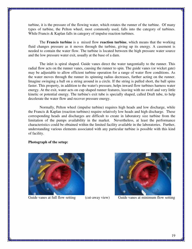
Photograph of the setup:
Guide vanes at full flow setting (cut-away view) Guide vanes at minimum flow setting
20
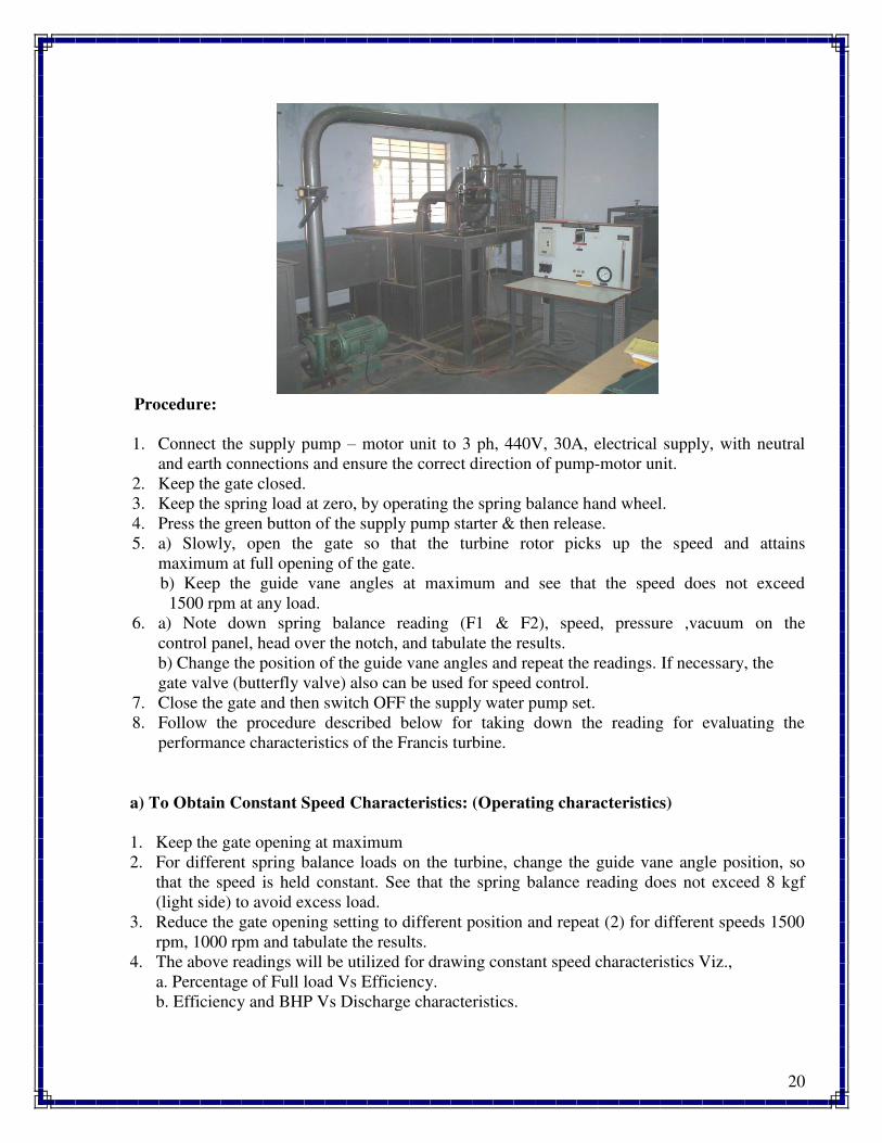
Procedure:
1. Connect the supply pump – motor unit to 3 ph, 440V, 30A, electrical supply, with neutral
and earth connections and ensure the correct direction of pump-motor unit.
2. Keep the gate closed.
3. Keep the spring load at zero, by operating the spring balance hand wheel.
4. Press the green button of the supply pump starter & then release.
5. a) Slowly, open the gate so that the turbine rotor picks up the speed and attains
maximum at full opening of the gate.
b) Keep the guide vane angles at maximum and see that the speed does not exceed
1500 rpm at any load.
6. a) Note down spring balance reading (F1 & F2), speed, pressure ,vacuum on the
control panel, head over the notch, and tabulate the results.
b) Change the position of the guide vane angles and repeat the readings. If necessary, the
gate valve (butterfly valve) also can be used for speed control.
7. Close the gate and then switch OFF the supply water pump set.
8. Follow the procedure described below for taking down the reading for evaluating the
performance characteristics of the Francis turbine.
a) To Obtain Constant Speed Characteristics: (Operating characteristics)
1. Keep the gate opening at maximum
2. For different spring balance loads on the turbine, change the guide vane angle position, so
that the speed is held constant. See that the spring balance reading does not exceed 8 kgf
(light side) to avoid excess load.
3. Reduce the gate opening setting to different position and repeat (2) for different speeds 1500
rpm, 1000 rpm and tabulate the results.
4. The above readings will be utilized for drawing constant speed characteristics Viz.,
a. Percentage of Full load Vs Efficiency.
b. Efficiency and BHP Vs Discharge characteristics.
21
b) To obtain Constant Head Characteristics: (Main Characteristics)
1. Select the guide vane angle position.
2. Keep the gate closed, and start the pump.
3. Slowly open the gate and set the pressure on the gauge.
4. For different electrical loads, change the guide vane angle position and maintain the
constant head and tabulate the results as given in Table – II.
c) To obtain Run – Away Speed Characteristics:
1. Switch OFF the entire load on the turbine.
2. Keep guide vane angle at optimum position.
3. Slowly open the gate to maximum and note down the turbine speed. This is the runaway
speed which is maximum.
Note:
Run – away speed is also influenced by the tightening in gland packing of the turbine shaft.
More is the tightness, less is the run – away speed.
Performance under Unit Head – Unit Quantities:
In order to predict the behavior of a turbine working under varying conditions and to facilitate
comparison between the performances of the turbines of the same type but having different
outputs and speeds and working under different heads, it is often convenient to express the test
results in terms of certain unit quantities.
From the output of a turbine corresponding to different working heads (Table of Calculations –
II) it is possible to compute the output which would be developed if the head was reduced to unit
(say 1mt); the speed being adjustable so that the efficiency remains unaffected.
a. Unit Speed: HN/Nu
b. Unit power: 3/2u P/HP
c. Unit Discharge: HQ/Qu
Specific Speed:
The specific speed of any turbine is the speed in rpm of a turbine geometrically similar to the
actual turbine but of such a size that under corresponding conditions it will develop 1 metric
horse power when working under unit head (i.e., 1 meter.).
The specific speed is usually computed for the operating conditions corresponding to the
maximum efficiency.
5/4u
H
PNN
22
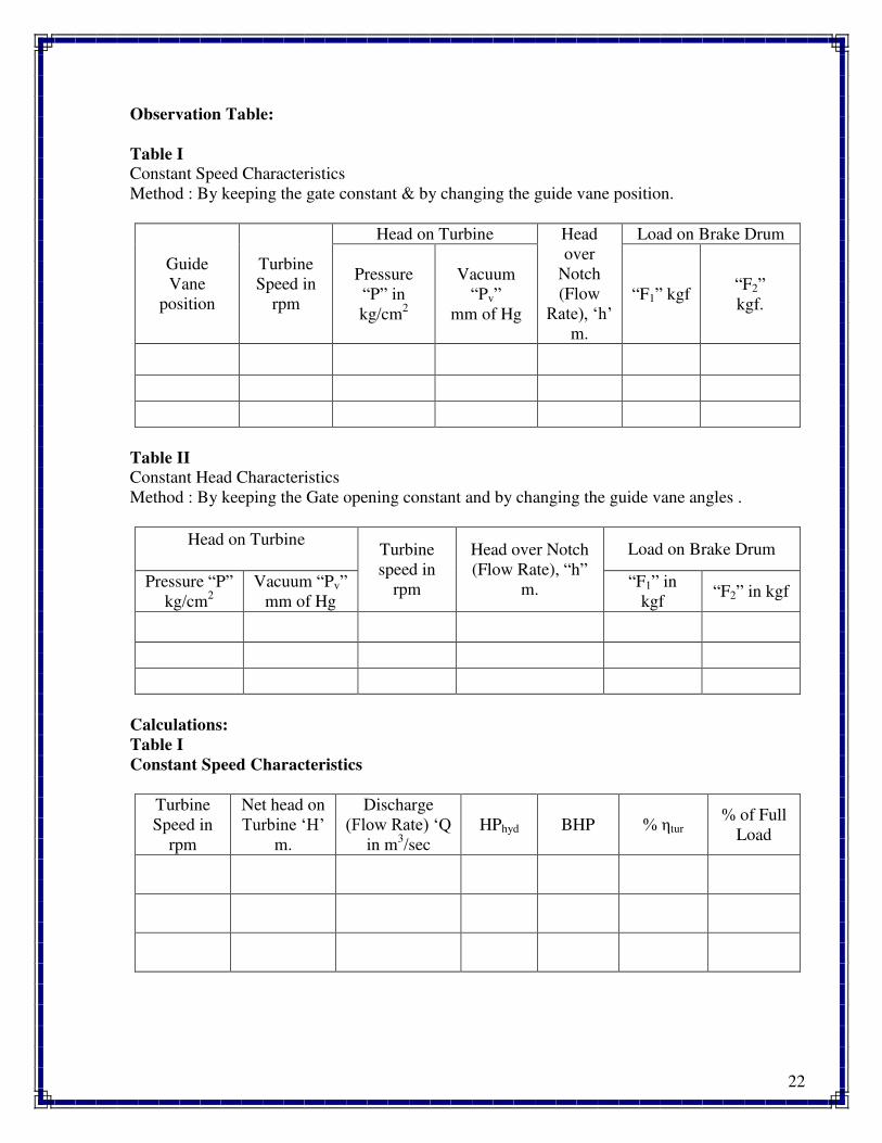
Observation Table:
Table I
Constant Speed Characteristics
Method : By keeping the gate constant & by changing the guide vane position.
Guide
Vane
position
Turbine
Speed in
rpm
Head on Turbine Head
over
Notch
(Flow
Rate), ‘h’ m.
Load on Brake Drum
Pressure
“P” in
kg/cm2
Vacuum
“Pv”
mm of Hg
“F1” kgf “F2”
kgf.
Table II
Constant Head Characteristics
Method : By keeping the Gate opening constant and by changing the guide vane angles .
Head on Turbine
Turbine
speed in
rpm
Head over Notch
(Flow Rate), “h”
m.
Load on Brake Drum
Pressure “P”
kg/cm2
Vacuum “Pv”
mm of Hg
“F1” in
kgf “F2” in kgf
Calculations:
Table I
Constant Speed Characteristics
Turbine
Speed in
rpm
Net head on
Turbine ‘H’ m.
Discharge
(Flow Rate) ‘Q in m
3/sec
HPhyd BHP % tur % of Full
Load
23
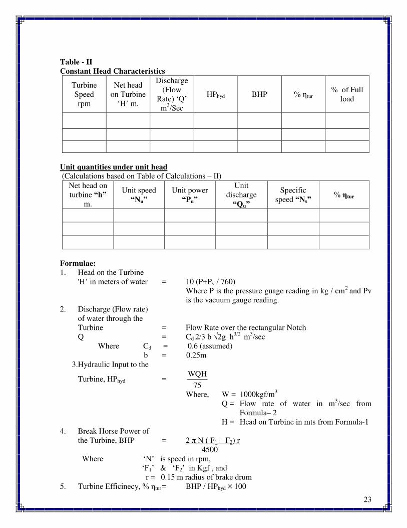
Table - II
Constant Head Characteristics
Turbine
Speed
rpm
Net head
on Turbine
‘H’ m.
Discharge
(Flow
Rate) ‘Q’ m
3/Sec
HPhyd BHP % tur % of Full
load
Unit quantities under unit head
(Calculations based on Table of Calculations – II)
Net head on
turbine “h”
m.
Unit speed
“Nu”
Unit power
“Pu”
Unit
discharge
“Qu”
Specific
speed “Ns” % ηtur
Formulae:
1. Head on the Turbine
'H’ in meters of water = 10 (P+Pv / 760)
Where P is the pressure guage reading in kg / cm2
and Pv
is the vacuum gauge reading.
2. Discharge (Flow rate)
of water through the
Turbine = Flow Rate over the rectangular Notch
Q = Cd 2/3 b √2g h3/2 m
3/sec
Where Cd = 0.6 (assumed)
b = 0.25m
3.Hydraulic Input to the
Turbine, HPhyd = 75
WQH
Where, W = 1000kgf/m3
Q = Flow rate of water in m3/sec from
Formula– 2
H = Head on Turbine in mts from Formula-1
4. Break Horse Power of
the Turbine, BHP = 2 π N ( F1 – F2) r
4500
Where ‘N’ is speed in rpm, ‘F1’ & ‘F2’ in Kgf , and
r = 0.15 m radius of brake drum
5. Turbine Efficinecy, % tur = BHP / HPhyd × 100
24
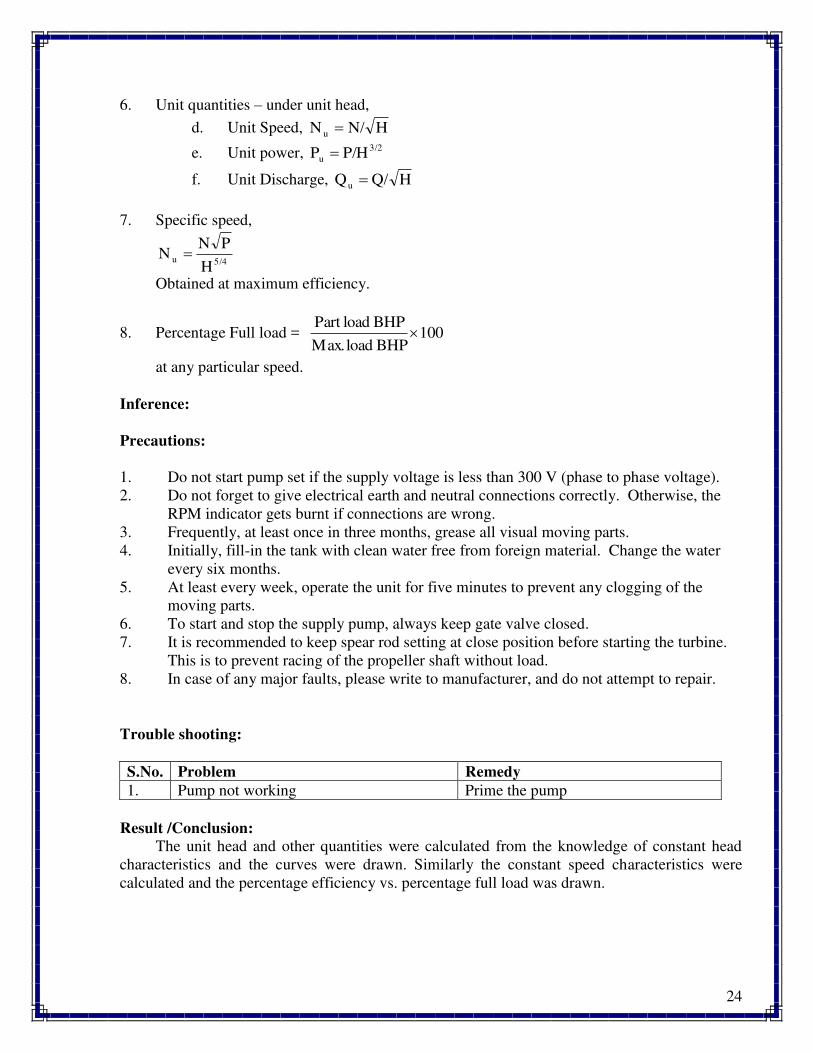
6. Unit quantities – under unit head,
d. Unit Speed, HN/N u
e. Unit power, 3/2
u P/HP
f. Unit Discharge, HQ/Qu
7. Specific speed,
5/4u
H
PNN
Obtained at maximum efficiency.
8. Percentage Full load = 100BHPload.Max
BHPloadPart
at any particular speed.
Inference:
Precautions:
1. Do not start pump set if the supply voltage is less than 300 V (phase to phase voltage).
2. Do not forget to give electrical earth and neutral connections correctly. Otherwise, the
RPM indicator gets burnt if connections are wrong.
3. Frequently, at least once in three months, grease all visual moving parts.
4. Initially, fill-in the tank with clean water free from foreign material. Change the water
every six months.
5. At least every week, operate the unit for five minutes to prevent any clogging of the
moving parts.
6. To start and stop the supply pump, always keep gate valve closed.
7. It is recommended to keep spear rod setting at close position before starting the turbine.
This is to prevent racing of the propeller shaft without load.
8. In case of any major faults, please write to manufacturer, and do not attempt to repair.
Trouble shooting:
S.No. Problem Remedy
1. Pump not working Prime the pump
Result /Conclusion:
The unit head and other quantities were calculated from the knowledge of constant head
characteristics and the curves were drawn. Similarly the constant speed characteristics were
calculated and the percentage efficiency vs. percentage full load was drawn.
25
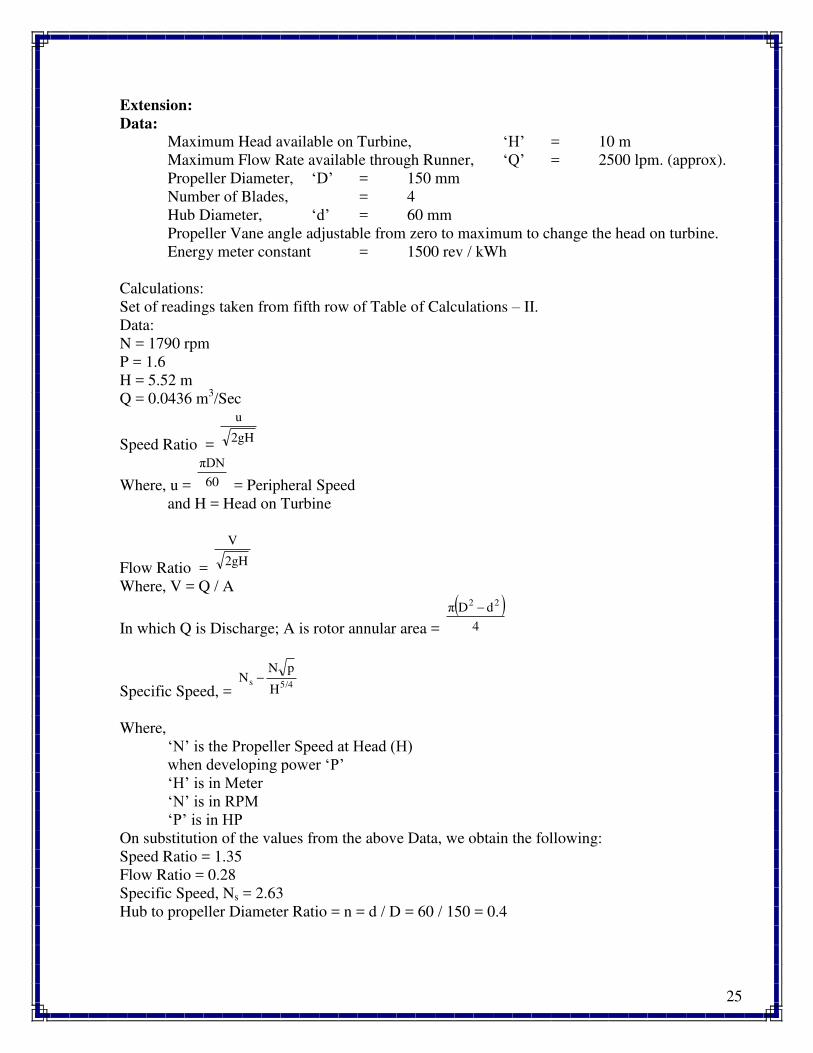
Extension:
Data:
Maximum Head available on Turbine, ‘H’ = 10 m
Maximum Flow Rate available through Runner, ‘Q’ = 2500 lpm. (approx).
Propeller Diameter, ‘D’ = 150 mm
Number of Blades, = 4
Hub Diameter, ‘d’ = 60 mm
Propeller Vane angle adjustable from zero to maximum to change the head on turbine.
Energy meter constant = 1500 rev / kWh
Calculations:
Set of readings taken from fifth row of Table of Calculations – II.
Data:
N = 1790 rpm
P = 1.6
H = 5.52 m
Q = 0.0436 m3/Sec
Speed Ratio = 2gH
u
Where, u = 60
πDN
= Peripheral Speed
and H = Head on Turbine
Flow Ratio = 2gH
V
Where, V = Q / A
In which Q is Discharge; A is rotor annular area =
4
dDπ 22
Specific Speed, = 5/4s
H
pNN
Where,
‘N’ is the Propeller Speed at Head (H) when developing power ‘P’ ‘H’ is in Meter ‘N’ is in RPM
‘P’ is in HP
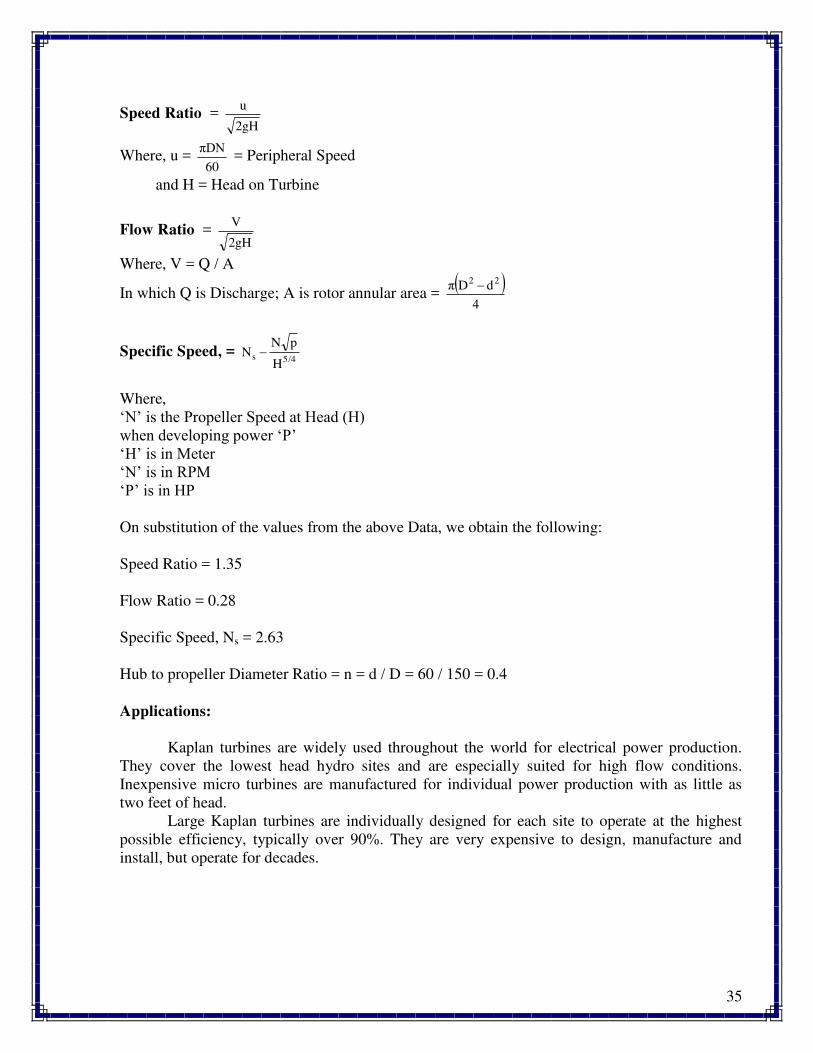
On substitution of the values from the above Data, we obtain the following:
Speed Ratio = 1.35
Flow Ratio = 0.28
Specific Speed, Ns = 2.63
Hub to propeller Diameter Ratio = n = d / D = 60 / 150 = 0.4

26
Questions:
1. On what principle the Francis turbine works?
2. What is the shape and function of draft tube in Francis turbine?
3. What is the purpose of guide vanes?
4. Define unit quantities and specific speed.
5. What type of flow occurs in Francis turbine?
27
Experiment No. 4
KAPLAN TURBINE
Aim:
To determine the performance characteristics of Kaplan turbine under constant head and
constant speed.
Apparatus Required:
Kaplan turbine test rig.
Specifications:
The actual experimental set-up consists of a centrifugal pump set turbine unit, sump tank,
notch tank arranged in such a way that the whole unit works on re-circulating water system. The
centrifugal pump set supplies the water from the sump tank to the turbine through gate valve
which has the marking to meter the known quantity of water. The water after passing through
the turbine unit enters the collecting tank through the draft tube. The water then flows back to
the sump tank through the notch tank with rectangular notch for the measurement of flow rate.
The loading of the turbine is achieved by electrical AC generator connected to lamp
bank. The provisions for; measurement of electrical energy AC voltmeter and ammeter turbine
speed (digital RPM indicator), Head on the turbine (pressure gauge), are built-in on the control
panel.
Supply Pump / motor Capacity : 12 hp, 3 ph, 440V, 50 Hz AC.
Turbine : 150 mm dia. Propeller with four blades.
: Propeller blade angles adjustable from maximum to
minimum.
: Run-away speed – 2500 rpm (approx.).
: Max. flow of water – 2500 lpm (approx.).
: Max. Head – 10 m. (approx.).
Loading : AC generator.
Provisions : a. Flow rate by notch, Cd = 0.6 (assumed).
b. Head on turbine by pressure gauge of range “0.2kg /
cm2 and vacuum gauge :1 – 760 mm of Hg
c. Electrical load change by toggle switch (maximum
connected load : 2000 watts).
d. Electrical load measurement by energy meter.
e. Voltage & current of generator by analog meters.
f. Propeller speed by digital rpm indicator
g. Supply water control by gate valve.
Electrical Supply : 3ph, 440V, AC, 30A, with neutral & earth.
Note: Volume of water required for operation unit : 3000 lt. (approx.).
28
Theory:
Hydraulic (or Water) turbines are the machines which use the energy of water (Hydro –
Power) and convert it into mechanical energy. Thus the turbine becomes the prime-mover to run
the electrical generators to produce the electricity, Viz., Hydro-Electric Power.
The turbines are classified as Impulse & Reaction types. In impulse turbine, the head of
water is completely converted into a jet, which impulses the forces on the turbine. In reaction
turbine, it is the pressure of the flowing water, which rotates the runner of the turbine. Of many
types of turbine, the Pelton wheel, most commonly used, falls into the category of turbines.
While Francis & Kaplan falls in category of impulse reaction turbines.
The Kaplan turbine is an inward flow reaction turbine, which means that the working
fluid changes pressure as it moves through the turbine and gives up its energy. The design
combines radial and axial features.
The inlet is a scroll-shaped tube that wraps around the turbine's wicket gate. Water is
directed tangentially, through the wicket gate, and spirals on to a propeller shaped runner,
causing it to spin. Between the scroll casing and the runner, the water turns through right angle
into the axial direction and passes through the runner and thus rotating the runner shaft. The
runner has four blades which can be turned about their own axis so that the angle of inclination
may be adjusted while the turbine is in motion. When runner blade angles are varied, high
efficiency can be maintained over wide range of operating conditions. In other words even at
part loads, when a low discharge is flowing through the runner, a high efficiency can be attained
in case of Kaplan turbine, whereas this provision does not exist in Francis & Propeller turbines
where, the runner blade angles are fixed and integral with hub.
The outlet is a specially shaped draft tube that helps decelerate the water and recover kinetic
energy. The turbine does not need to be at the lowest point of water flow, as long as the draft
tube remains full of water. A higher turbine location, however, increases the suction that is
imparted on the turbine blades by the draft tube. The resulting pressure drop may lead to
cavitation..
Normally, Pelton wheel (impulse turbine) requires high heads and low discharge, while
the Francis & Kaplan (reaction turbines) require relatively low heads and high discharge. These
corresponding he1ds and discharge are difficult to create in laboratory size turbine from the
limitation of the pumps availability in the market. Nevertheless, at least the performance
characteristics could be obtained within the limited facility available in the laboratories. Further,
understanding various elements associated with any particular turbine is possible with this kind
of facility.
29
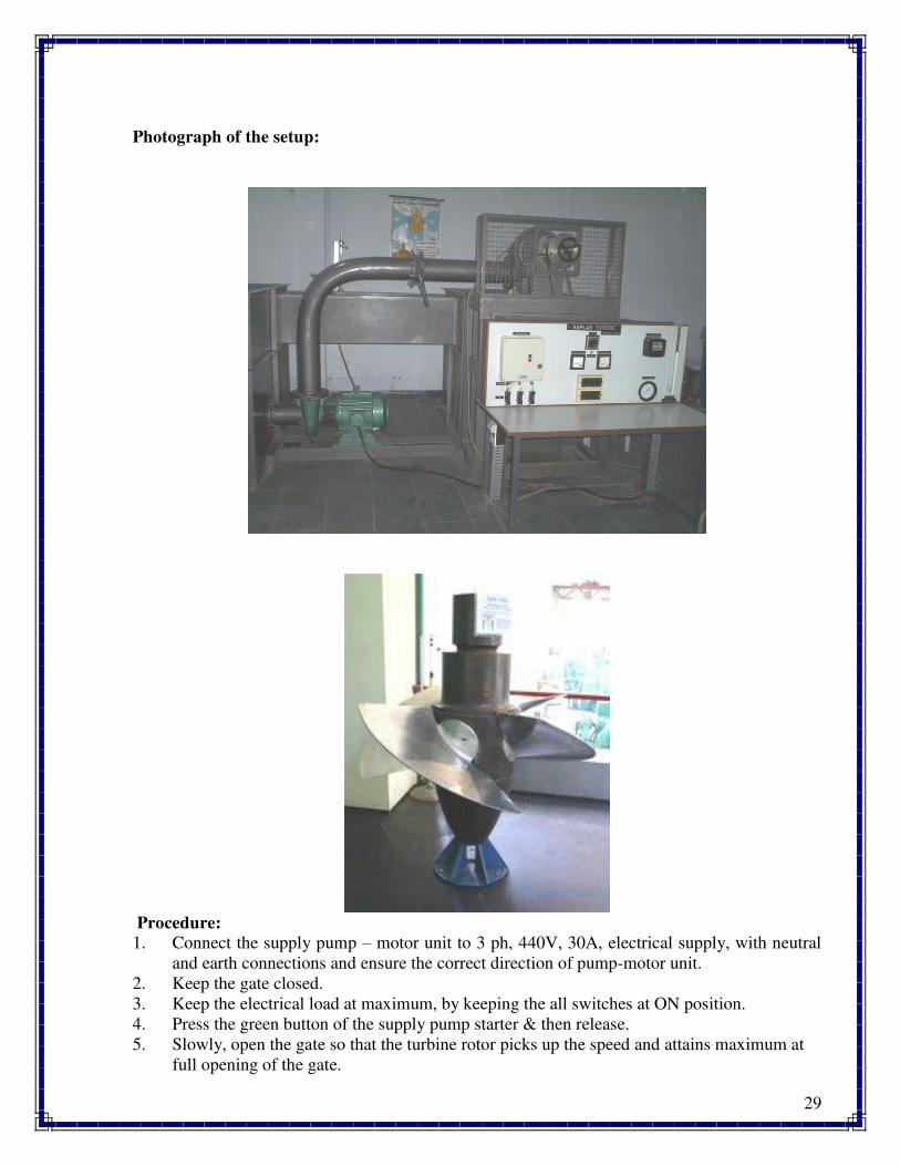
Photograph of the setup:
Procedure:
1. Connect the supply pump – motor unit to 3 ph, 440V, 30A, electrical supply, with neutral
and earth connections and ensure the correct direction of pump-motor unit.
2. Keep the gate closed.
3. Keep the electrical load at maximum, by keeping the all switches at ON position.
4. Press the green button of the supply pump starter & then release.
5. Slowly, open the gate so that the turbine rotor picks up the speed and attains maximum at
full opening of the gate.
30
6. Note down the voltage and current, speed, pressure vacuum on the control panel, head over
the notch, and tabulate the results.
7. Close the gate and then switch OFF the supply water pump set.
8. Follow the procedure described below for taking down the reading for evaluating the
performance characteristics of the Kaplan turbine.
To obtain constant speed characteristics: (operating characteristics)
1. Keep the gate opening at maximum
2. For different electrical loads on the turbine / generator, change the gate position, so that the
speed is held constant; say at 1500 rpm. See that the voltage does not exceed 250 V to
avoid excess voltage on Bulbs.
3. Reduce the gate opening setting to different position and repeat (2) for different speeds
1500 rpm, 1000 rpm and tabulate the results.
4. The above readings will be utilized for drawing constant speed characteristics Viz.,
a. Percentage of full load V/s efficiency.
b. Efficiency and BHP V/s discharge characteristics.
To obtain constant head characteristics: (main characteristics)
1. Select the propeller vane angle position.
2. Keep the gate closed, and start the pump.
3. Slowly open the gate and set the pressure on the gauge.
4. For different electrical load, change the rotor pitch position and maintain the constant head
and tabulate the results as given in Table – II.
To obtain Run – Away speed characteristics:
1. Switch OFF the entire load on the turbine and the voltmeter.
2. Keep propeller vane angle at optimum position (Head, h = 0.75 Kg / cm2).
3. Slowly open the gate to maximum and note down the turbine speed. This is the runaway
speed which is maximum.
Note:
Run-away speed is also influenced by the tightening in gland packing of the turbine shaft. More
is the tightness, less is the run-away speed.
Performance under unit head – unit quantities:
In order to predict the behavior of a turbine working under varying conditions and to facilitate
comparison between the performances of the turbines of the same type but having different
outputs and speeds and working under different heads, it is often convenient to express the test
results in terms of certain unit quantities.
From the output of a turbine corresponding to different working heads (Table of Calculations –
II) it is possible to compute the output which would be developed if the head was reduced to unit
(say 1mt); the speed being adjustable so that the efficiency remains unaffected.
31
a. Unit Speed, HN/Nu
b. Unit power, 3/2u P/HP
c. Unit Discharge, HQ/Qu
Specific Speed:
The specific speed of any turbine is the speed in rpm of a turbine geometrically similar to
the actual turbine but of such a size that under corresponding conditions it will develop 1 metric
horse power when working under unit head (i.e., 1 meter.).
The specific speed is usually computed for the operating conditions corresponding to the
maximum efficiency.
5/4u
H
PNN
Observation Table:
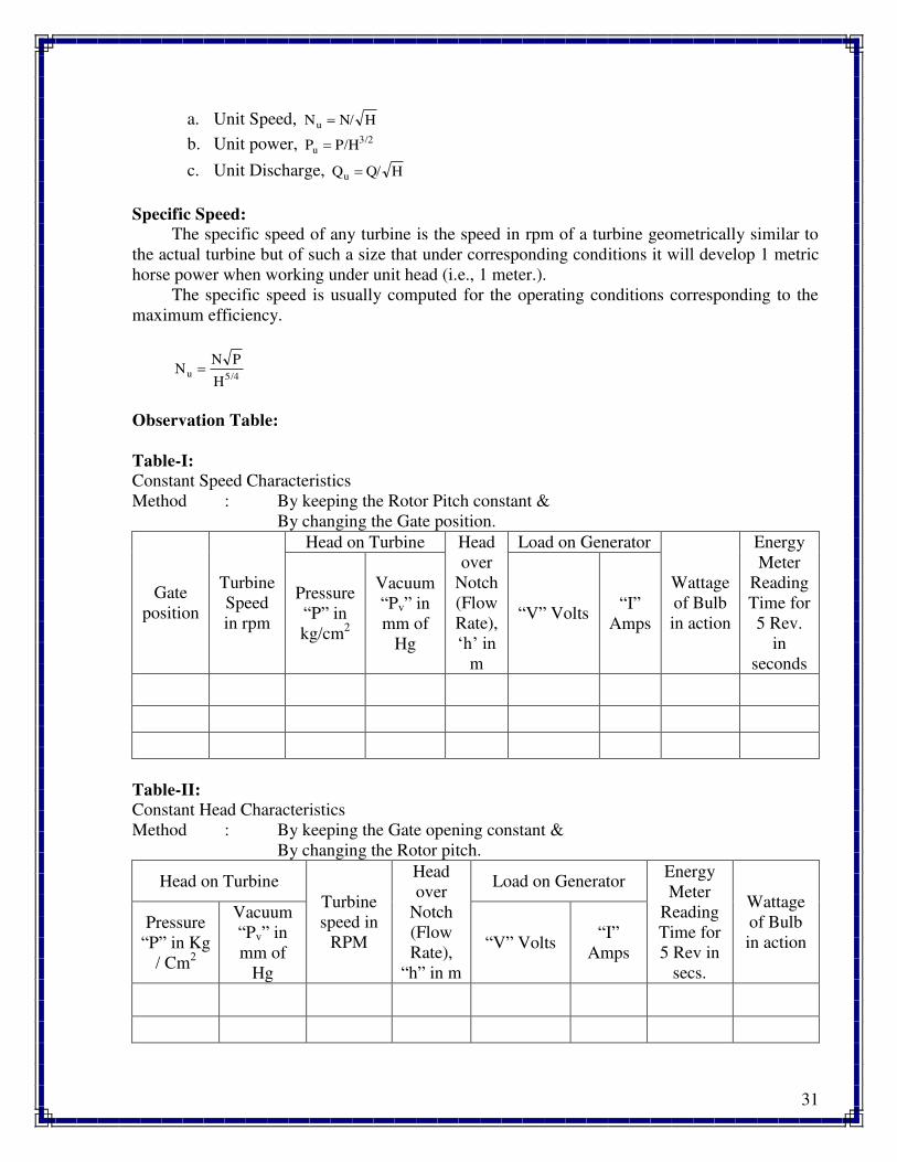
Table-I:
Constant Speed Characteristics
Method : By keeping the Rotor Pitch constant &
By changing the Gate position.
Gate
position
Turbine
Speed
in rpm
Head on Turbine Head
over
Notch
(Flow
Rate),
‘h’ in m
Load on Generator
Wattage
of Bulb
in action
Energy
Meter
Reading
Time for
5 Rev.
in
seconds
Pressure
“P” in
kg/cm2
Vacuum
“Pv” in
mm of
Hg
“V” Volts “I”
Amps
Table-II:
Constant Head Characteristics
Method : By keeping the Gate opening constant &
By changing the Rotor pitch.
Head on Turbine
Turbine
speed in
RPM
Head
over
Notch
(Flow
Rate),
“h” in m
Load on Generator Energy
Meter
Reading
Time for
5 Rev in
secs.
Wattage
of Bulb
in action Pressure
“P” in Kg
/ Cm2
Vacuum
“Pv” in
mm of
Hg
“V” Volts “I”
Amps
32
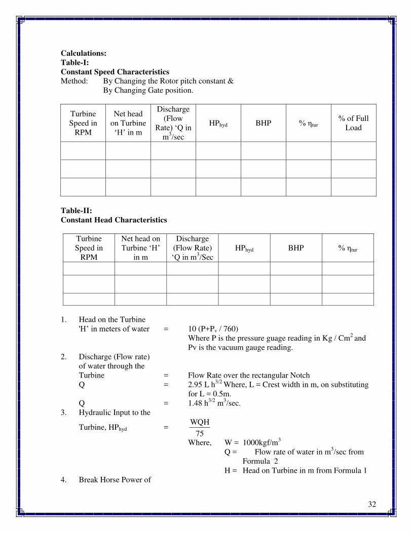
Calculations:
Table-I:
Constant Speed Characteristics
Method: By Changing the Rotor pitch constant &
By Changing Gate position.
Turbine
Speed in
RPM
Net head
on Turbine
‘H’ in m
Discharge
(Flow
Rate) ‘Q in m
3/sec
HPhyd BHP % tur % of Full
Load
Table-II:
Constant Head Characteristics
Turbine
Speed in
RPM
Net head on
Turbine ‘H’ in m
Discharge
(Flow Rate)
‘Q in m3/Sec
HPhyd BHP % tur
1. Head on the Turbine
'H’ in meters of water = 10 (P+Pv / 760)
Where P is the pressure guage reading in Kg / Cm2
and
Pv is the vacuum gauge reading.
2. Discharge (Flow rate)
of water through the
Turbine = Flow Rate over the rectangular Notch
Q = 2.95 L h3/2
Where, L = Crest width in m, on substituting
for L = 0.5m.
Q = 1.48 h3/2
m3/sec.
3. Hydraulic Input to the
Turbine, HPhyd = 75
WQH
Where, W = 1000kgf/m3
Q = Flow rate of water in m3/sec from
Formula 2
H = Head on Turbine in m from Formula 1
4. Break Horse Power of
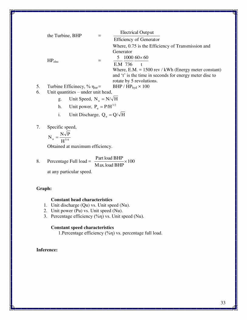
33
the Turbine, BHP = GeneratorofEfficiency
OutputElectrical
Where, 0.75 is the Efficiency of Transmission and
Generator
HPelec = t
6060
736
1000
E.M
5
Where, E.M. = 1500 rev / kWh (Energy meter constant)
and ‘t’ is the time in seconds for energy meter disc to rotate by 5 revolutions.
5. Turbine Efficinecy, % tur = BHP / HPhyd × 100
6. Unit quantities – under unit head,
g. Unit Speed, HN/N u
h. Unit power, 3/2
u P/HP
i. Unit Discharge, HQ/Qu
7. Specific speed,
5/4u
H
PNN
Obtained at maximum efficiency.
8. Percentage Full load = 100BHPload.Max
BHPloadPart
at any particular speed.
Graph:
Constant head characteristics
1. Unit discharge (Qu) vs. Unit speed (Nu).
2. Unit power (Pu) vs. Unit speed (Nu).
3. Percentage efficiency (% ) vs. Unit speed (Nu).
Constant speed characteristics
1.Percentage efficiency (% ) vs. percentage full load.
Inference:
34
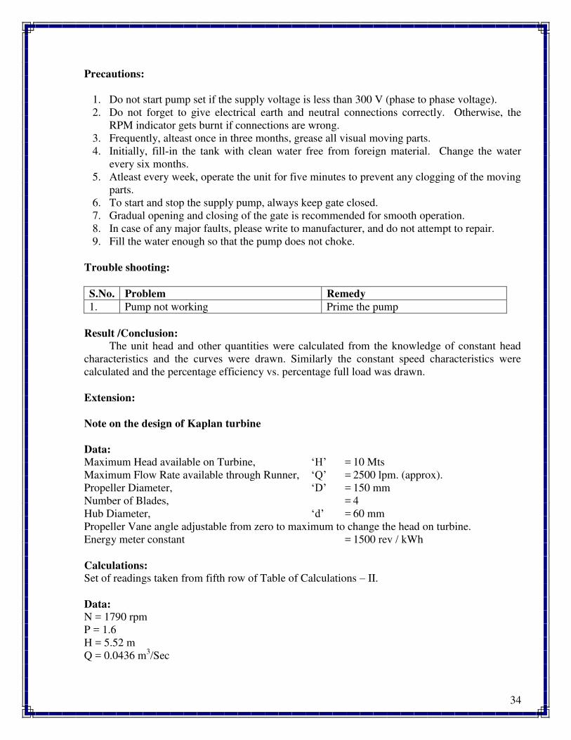
Precautions:
1. Do not start pump set if the supply voltage is less than 300 V (phase to phase voltage).
2. Do not forget to give electrical earth and neutral connections correctly. Otherwise, the
RPM indicator gets burnt if connections are wrong.
3. Frequently, alteast once in three months, grease all visual moving parts.
4. Initially, fill-in the tank with clean water free from foreign material. Change the water
every six months.
5. Atleast every week, operate the unit for five minutes to prevent any clogging of the moving
parts.
6. To start and stop the supply pump, always keep gate closed.
7. Gradual opening and closing of the gate is recommended for smooth operation.
8. In case of any major faults, please write to manufacturer, and do not attempt to repair.
9. Fill the water enough so that the pump does not choke.
Trouble shooting:
S.No. Problem Remedy
1. Pump not working Prime the pump
Result /Conclusion:
The unit head and other quantities were calculated from the knowledge of constant head
characteristics and the curves were drawn. Similarly the constant speed characteristics were
calculated and the percentage efficiency vs. percentage full load was drawn.
Extension:
Note on the design of Kaplan turbine
Data:
Maximum Head available on Turbine, ‘H’ = 10 Mts
Maximum Flow Rate available through Runner, ‘Q’ = 2500 lpm. (approx).
Propeller Diameter, ‘D’ = 150 mm
Number of Blades, = 4
Hub Diameter, ‘d’ = 60 mm
Propeller Vane angle adjustable from zero to maximum to change the head on turbine.
Energy meter constant = 1500 rev / kWh
Calculations:
Set of readings taken from fifth row of Table of Calculations – II.
Data:
N = 1790 rpm
P = 1.6
H = 5.52 m
Q = 0.0436 m3/Sec
35
Speed Ratio = 2gH
u
Where, u = 60
πDN = Peripheral Speed
and H = Head on Turbine
Flow Ratio = 2gH
V
Where, V = Q / A
In which Q is Discharge; A is rotor annular area =
4
dDπ 22
Specific Speed, = 5/4s
H
pNN
Where,
‘N’ is the Propeller Speed at Head (H) when developing power ‘P’ ‘H’ is in Meter ‘N’ is in RPM
‘P’ is in HP
On substitution of the values from the above Data, we obtain the following:
Speed Ratio = 1.35
Flow Ratio = 0.28
Specific Speed, Ns = 2.63
Hub to propeller Diameter Ratio = n = d / D = 60 / 150 = 0.4
Applications:
Kaplan turbines are widely used throughout the world for electrical power production.
They cover the lowest head hydro sites and are especially suited for high flow conditions.
Inexpensive micro turbines are manufactured for individual power production with as little as
two feet of head.
Large Kaplan turbines are individually designed for each site to operate at the highest
possible efficiency, typically over 90%. They are very expensive to design, manufacture and
install, but operate for decades.

36
Questions:
1. On what principle the Kaplan turbine works?
2. What is the shape and function of draft tube?
3. Why V notch is not used in Kaplan turbine?
4. Define unit quantities and specific speed.
5. What is the nature of flow in Kaplan turbine?
37
Experiment No. 5
RECIPROCATING PUMP
Aim:
To find the overall efficiency of a Reciprocating Pump and plot the following characteristics.
a. HP Hydraulic Vs HPElectric
b. overall Vs HPElectric
Apparatus Required:
Reciprocating pump test rig, stop watch.
The present Reciprocating Pump Test Rig is a self-contained unit operated on Closed Circuit
(Recirculation) Basis. The main components are singe acting Single Cylinder Reciprocating
Pump, AC Motor, Sump Tank, Collecting Tank, control Panel are mounted on rigid frame work
with anti-vibration mounts and arranged with the following provisions:
1. To run the pump at 3 different speeds using Stepped Cone Pulley arrangement and
AC Motor.
2. To measure the input horse power to the pump using energy meter reading.
3. To measure the speed in rpm of the motor and the pump, separately.
4. To measure the delivery and suction heads using pressure and vacuum gauges
separately. (The delivery head pressure tapping is connected, upstream of delivery
valve, and that of the suction tapping downstream of suction valve).
5. To change the head and flow rate using control valves.
6. To measure the discharge using collecting tank fitted with tank level indicator.
Specifications:
Electrical Supply : 230V, AC, 1 Phase, 50 Hz with Neutral & Earth Connections.
Motor : AC Motor, 1.5 HP, 1500 RPM.
Reciprocating Pump : Single acting single cylinder.
Pressure Gauge : 2 kg / cm2
Vacuum Gauge : 0 – 760 mm of Hg
Energy Meter Constant : 1500 rev / kWh.
Speed Indicator : 0 – 9999 rpm (Digital type).
Control Valves : For suction & delivery.
Measuring (Metering) Tank : 0.25m2
Theory:
In general, a pump may be defined as a mechanical device which, when interposed in a
pipe line, converts the mechanical energy supplied to it from some external source into hydraulic
energy, thus resulting in the flow of liquid from lower potential to higher potential.
The pumps are of major concern to most Engineers and Technicians. The types of pump vary in
principle and design. The selection of the pump for any particular application is to be done by
understanding their characteristics. The most commonly used pumps for domestic, agricultural
38
and industrial purposes are: Centrifugal, Piston, Axial Flow (Stage pumps), Air Jet, Diaphragm
and Turbine pumps. Most of these pumps fall into the main class, namely, Rotodynamic,
Reciprocating (Positive Displacement), Fluid (Air) operated pumps.
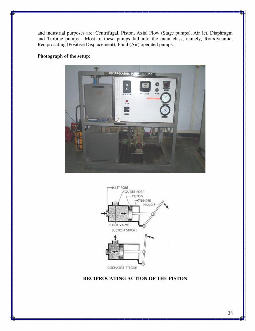
Photograph of the setup:
RECIPROCATING ACTION OF THE PISTON
39
Procedure:
All the necessary instrumentation along with its accessories are readily connected. It is just
enough to follow the instructions below:
1. Fill in the sump tank with clean water.
2. Keep the delivery and suction valves open.
3. Connect the power cable to 1 ph, 220 V, 15 Amps.
4. Select the required speed using stepped cone pulley arrangement.
5. Switch ON the mains so that the mains ON indicator glows. Now, switch on the
motor.
6. Note down the speed from digital rpm indicator.
7. Note down the Pressure Gauge, Vacuum Gauge and time for number of revolutions of
energy meter disc at full opening of delivery and suction valve.
8. Operate the butterfly valve to note down the collecting tank reading against the
known time, and keep it open when the readings are not taken.
9. Repeat the experiment for different openings of the delivery valve (Pressure & Flow
Rate). Note down the readings as indicated in tabular column.
10. Repeat the experiment for different speeds and repeat the steps (4 & 9).
11. After the experiment is over, keep the delivery valve open and switch OFF the mains.
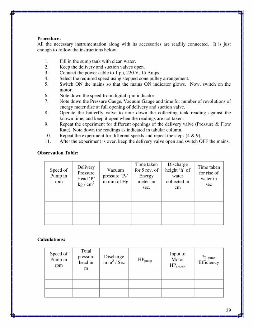
Observation Table:
Speed of
Pump in
rpm
Delivery
Pressure
Head ‘P’ kg / cm
2
Vacuum
pressure ‘Pv’ in mm of Hg
Time taken
for 5 rev. of
Energy
meter in
sec.
Discharge
height ‘h’ of water
collected in
cm
Time taken
for rise of
water in
sec
Calculations:
Speed of
Pump in
rpm
Total
pressure
head in
m
Discharge
in m3 / Sec
HPpump
Input to
Motor
HPelectric
% pump
Efficiency
40
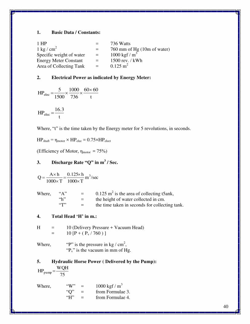
1. Basic Data / Constants:
1 HP = 736 Watts
1 kg / cm2 = 760 mm of Hg (10m of water)
Specific weight of water = 1000 kgf / m3
Energy Meter Constant = 1500 rev. / kWh
Area of Collecting Tank = 0.125 m2
2. Electrical Power as indicated by Energy Meter:
t
6060
736
1000
1500
5HPelec
t
16.3HPelec
Where, “t” is the time taken by the Energy meter for 5 revolutions, in seconds.
HPshaft = motor × HPelec = 0.75×HPelect
(Efficiency of Motor, motor = 75%)
3. Discharge Rate “Q” in m3 / Sec.
/secmT1000
h0.125
T1000
hAQ 3
Where, “A” = 0.125 m2 is the area of collecting t5ank,
“h” = the height of water collected in cm.
“T” = the time taken in seconds for collecting tank.
4. Total Head ‘H’ in m.:
H = 10 (Delivery Pressure + Vacuum Head)
= 10 [P + ( Pv / 760 ) ]
Where, “P” is the pressure in kg / cm2,
“Pv” is the vacuum in mm of Hg.
5. Hydraulic Horse Power ( Delivered by the Pump):
75
WQHHPpump
Where, “W” = 1000 kgf / m3
“Q” = from Formulae 3.
“H” = from Formulae 4.
41
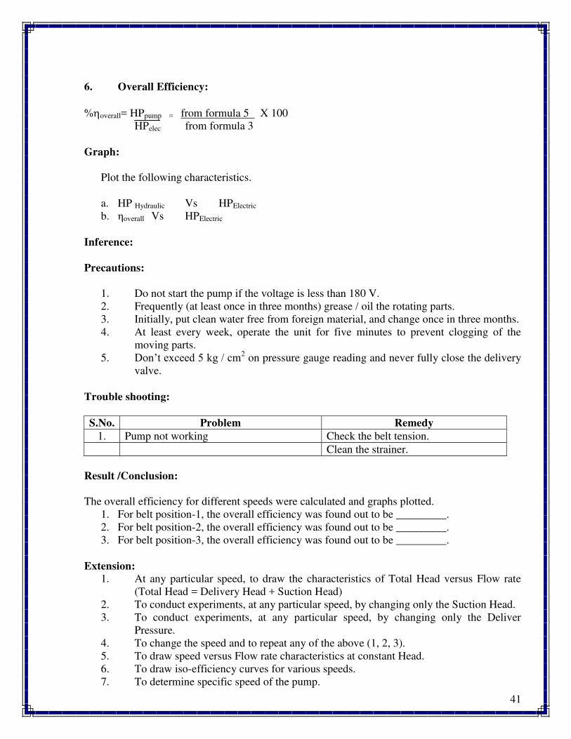
6. Overall Efficiency:
%overall= HPpump = from formula 5 X 100
HPelec from formula 3
Graph:
Plot the following characteristics.
a. HP Hydraulic Vs HPElectric
b. overall Vs HPElectric
Inference:
Precautions:
1. Do not start the pump if the voltage is less than 180 V.
2. Frequently (at least once in three months) grease / oil the rotating parts.
3. Initially, put clean water free from foreign material, and change once in three months.
4. At least every week, operate the unit for five minutes to prevent clogging of the
moving parts.
5. Don’t exceed η kg / cm2 on pressure gauge reading and never fully close the delivery
valve.
Trouble shooting:
S.No. Problem Remedy
1. Pump not working Check the belt tension.
Clean the strainer.
Result /Conclusion:
The overall efficiency for different speeds were calculated and graphs plotted.
1. For belt position-1, the overall efficiency was found out to be _________.
2. For belt position-2, the overall efficiency was found out to be _________.
3. For belt position-3, the overall efficiency was found out to be _________.
Extension:
1. At any particular speed, to draw the characteristics of Total Head versus Flow rate
(Total Head = Delivery Head + Suction Head)
2. To conduct experiments, at any particular speed, by changing only the Suction Head.
3. To conduct experiments, at any particular speed, by changing only the Deliver
Pressure.
4. To change the speed and to repeat any of the above (1, 2, 3).
5. To draw speed versus Flow rate characteristics at constant Head.
6. To draw iso-efficiency curves for various speeds.
7. To determine specific speed of the pump.
42
Applications:
1. To drill oil from deep wells.
2. To pump any liquid which is free from debris.
Questions:
1. What is the main aim of the experiment?
2. What is meant by a positive displacement pump?
3. What types of fluids are pumped by Reciprocating pumps?
4. What are the pumping characteristics of a Reciprocating pump?
5. What is the normal efficiency of a Reciprocating pump?
6. What are the normal precautions to be taken when operating a pump?
7. What is the function of air vessel?
43
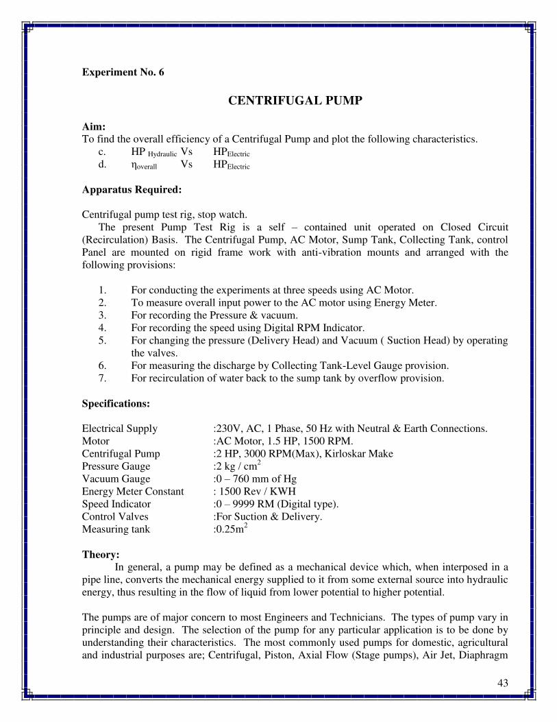
Experiment No. 6
CENTRIFUGAL PUMP
Aim:
To find the overall efficiency of a Centrifugal Pump and plot the following characteristics.
c. HP Hydraulic Vs HPElectric
d. overall Vs HPElectric
Apparatus Required:
Centrifugal pump test rig, stop watch.
The present Pump Test Rig is a self – contained unit operated on Closed Circuit
(Recirculation) Basis. The Centrifugal Pump, AC Motor, Sump Tank, Collecting Tank, control
Panel are mounted on rigid frame work with anti-vibration mounts and arranged with the
following provisions:
1. For conducting the experiments at three speeds using AC Motor.
2. To measure overall input power to the AC motor using Energy Meter.
3. For recording the Pressure & vacuum.
4. For recording the speed using Digital RPM Indicator.
5. For changing the pressure (Delivery Head) and Vacuum ( Suction Head) by operating
the valves.
6. For measuring the discharge by Collecting Tank-Level Gauge provision.
7. For recirculation of water back to the sump tank by overflow provision.
Specifications:
Electrical Supply :230V, AC, 1 Phase, 50 Hz with Neutral & Earth Connections.
Motor :AC Motor, 1.5 HP, 1500 RPM.
Centrifugal Pump :2 HP, 3000 RPM(Max), Kirloskar Make
Pressure Gauge :2 kg / cm2
Vacuum Gauge :0 – 760 mm of Hg
Energy Meter Constant : 1500 Rev / KWH
Speed Indicator :0 – 9999 RM (Digital type).
Control Valves :For Suction & Delivery.
Measuring tank :0.25m2
Theory:
In general, a pump may be defined as a mechanical device which, when interposed in a
pipe line, converts the mechanical energy supplied to it from some external source into hydraulic
energy, thus resulting in the flow of liquid from lower potential to higher potential.
The pumps are of major concern to most Engineers and Technicians. The types of pump vary in
principle and design. The selection of the pump for any particular application is to be done by
understanding their characteristics. The most commonly used pumps for domestic, agricultural
and industrial purposes are; Centrifugal, Piston, Axial Flow (Stage pumps), Air Jet, Diaphragm
44
and Turbine pumps. Most of these pumps fall into the main class, namely, Rotodynamic,
Reciprocating (Positive Displacement), Fluid (Air) operated pumps.
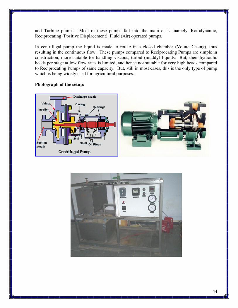
In centrifugal pump the liquid is made to rotate in a closed chamber (Volute Casing), thus
resulting in the continuous flow. These pumps compared to Reciprocating Pumps are simple in
construction, more suitable for handling viscous, turbid (muddy) liquids. But, their hydraulic
heads per stage at low flow rates is limited, and hence not suitable for very high heads compared
to Reciprocating Pumps of same capacity. But, still in most cases, this is the only type of pump
which is being widely used for agricultural purposes.
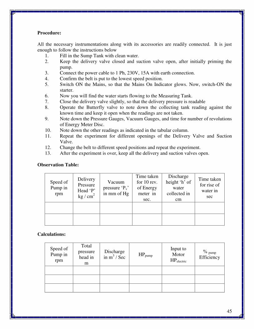
Photograph of the setup:
45
Procedure:
All the necessary instrumentations along with its accessories are readily connected. It is just
enough to follow the instructions below
1. Fill in the Sump Tank with clean water.
2. Keep the delivery valve closed and suction valve open, after initially priming the
pump.
3. Connect the power cable to 1 Ph, 230V, 15A with earth connection.
4. Confirm the belt is put to the lowest speed position.
5. Switch ON the Mains, so that the Mains On Indicator glows. Now, switch-ON the
starter.
6. Now you will find the water starts flowing to the Measuring Tank.
7. Close the delivery valve slightly, so that the delivery pressure is readable
8. Operate the Butterfly valve to note down the collecting tank reading against the
known time and keep it open when the readings are not taken.
9. Note down the Pressure Gauges, Vacuum Gauges, and time for number of revolutions
of Energy Meter Disc.
10. Note down the other readings as indicated in the tabular column.
11. Repeat the experiment for different openings of the Delivery Valve and Suction
Valve.
12. Change the belt to different speed positions and repeat the experiment.
13. After the experiment is over, keep all the delivery and suction valves open.
Observation Table:
Speed of
Pump in
rpm
Delivery
Pressure
Head ‘P’ kg / cm
2
Vacuum
pressure ‘Pv’ in mm of Hg
Time taken
for 10 rev.
of Energy
meter in
sec.
Discharge
height ‘h’ of water
collected in
cm
Time taken
for rise of
water in
sec
Calculations:
Speed of
Pump in
rpm
Total
pressure
head in
m
Discharge
in m3 / Sec
HPpump
Input to
Motor
HPelectric
% pump
Efficiency
46
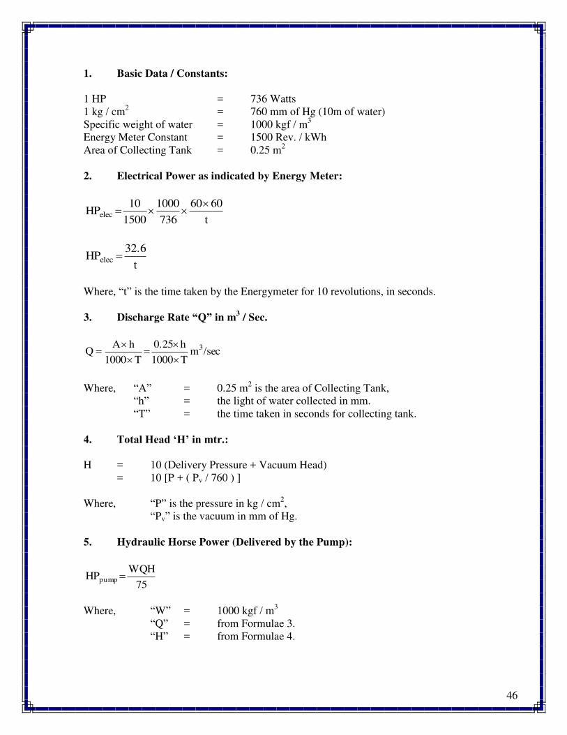
1. Basic Data / Constants:
1 HP = 736 Watts
1 kg / cm2 = 760 mm of Hg (10m of water)
Specific weight of water = 1000 kgf / m3
Energy Meter Constant = 1500 Rev. / kWh
Area of Collecting Tank = 0.25 m2
2. Electrical Power as indicated by Energy Meter:
t
6060
736
1000
1500
10HPelec
t
32.6HPelec
Where, “t” is the time taken by the Energymeter for 10 revolutions, in seconds.
3. Discharge Rate “Q” in m3 / Sec.
/secmT1000
h0.25
T1000
hAQ 3
Where, “A” = 0.25 m2 is the area of Collecting Tank,
“h” = the light of water collected in mm.
“T” = the time taken in seconds for collecting tank.
4. Total Head ‘H’ in mtr.:
H = 10 (Delivery Pressure + Vacuum Head)
= 10 [P + ( Pv / 760 ) ]
Where, “P” is the pressure in kg / cm2,
“Pv” is the vacuum in mm of Hg.
5. Hydraulic Horse Power (Delivered by the Pump):
75
WQHHPpump
Where, “W” = 1000 kgf / m3
“Q” = from Formulae 3.
“H” = from Formulae 4.
47
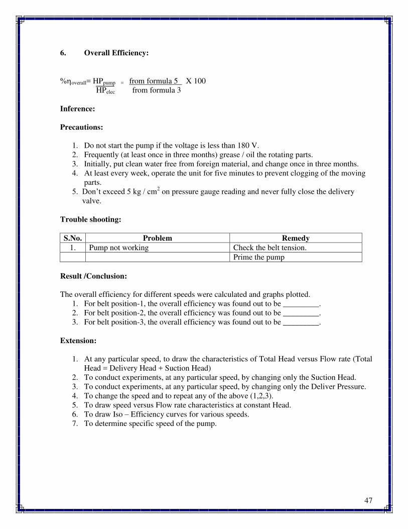
6. Overall Efficiency:
%overall= HPpump = from formula 5 X 100
HPelec from formula 3
Inference:
Precautions:
1. Do not start the pump if the voltage is less than 180 V.
2. Frequently (at least once in three months) grease / oil the rotating parts.
3. Initially, put clean water free from foreign material, and change once in three months.
4. At least every week, operate the unit for five minutes to prevent clogging of the moving
parts.
η. Don’t exceed η kg / cm2 on pressure gauge reading and never fully close the delivery
valve.
Trouble shooting:
S.No. Problem Remedy
1. Pump not working Check the belt tension.
Prime the pump
Result /Conclusion:
The overall efficiency for different speeds were calculated and graphs plotted.
1. For belt position-1, the overall efficiency was found out to be _________.
2. For belt position-2, the overall efficiency was found out to be _________.
3. For belt position-3, the overall efficiency was found out to be _________.
Extension:
1. At any particular speed, to draw the characteristics of Total Head versus Flow rate (Total
Head = Delivery Head + Suction Head)
2. To conduct experiments, at any particular speed, by changing only the Suction Head.
3. To conduct experiments, at any particular speed, by changing only the Deliver Pressure.
4. To change the speed and to repeat any of the above (1,2,3).
5. To draw speed versus Flow rate characteristics at constant Head.
6. To draw Iso – Efficiency curves for various speeds.
7. To determine specific speed of the pump.

48
Applications:
The most commonly used pumps for domestic, agricultural and industrial purposes are;
Centrifugal pumps. These pumps fall into the main class, namely, Rotodynamic pumps.
Questions:
1. What is meant by a Roto-dynamic machine?
2. What is meant by priming of a pump?
3. What energy is converted in a pump?
4. What type of fluids are pumped by centrifugal pumps?
5. What are the pumping characteristics of a centrifugal pump?
6. What is meant by efficiency of a pump?
49
Experiment No. 7
CALIBRATION OF VENTURIMETER
Aim:
To demonstrate the use of venturi meter as flow meter and to determine the co- efficient
of discharge in closed conduit or pipe flows. Also to plot the graph of theoretical discharge vs.
actual discharge (Qth Vs Qa) and co-efficient of discharge vs. actual discharge (Cd Vs Qa).
Apparatus Required:
1. A constant steady supply of water with a means of varying the flow rate using monoblock
pump.
2. A pipe line fitted with a venturi meter.
3. Measuring tank to measure the flow rate.
4. Tappings with ball valves are provided at inlet & throat of venturi meter and these are
connected to differential manometer.
5. Electronic digital timer with float switch for measurement of flow rate by collecting fixed
quantity of water.
Specifications:
1. Supply pipe of ø 21 mm (3/4") connected to inlet manifold.
2. Venturi meter size inlet ø 21.5 mm and throat ø 15 mm
3. Orifice meter size inlet ø 20 mm and throat ø 14 mm
4. Differential mercury manometer tapings provided at inlet and throat of venturi meter and
orifice meter. Manometer size 50 cm height.
5. Measuring tank size - 300 mm x 300 mm x 300 mm height.
Theory:
A Venturi Meter is a device which is used for measuring the rate of flow of fluid
through pipe line. The basic principle on which a venturimeter works is that by reducing the
cross-sectional area of the flow passage, a pressure difference is created between the inlet and
throat, and the measurement of the pressure difference enables the determination of the discharge
through the pipe.
A venturimeter consists of,
1. An inlet section followed by a convergent cone,
2. A cylindrical throat and
3. A gradually divergent cone.
The inlet section of the venturimeter is of the same diameter as that of the pipe which is followed
by a convergent cone. The convergent cone is a short pipe which tapers from the original size of
the pipe to that of the throat of the venturimeter. The throat of the venturimeter is a short parallel
sided tube having its cross sectional area smaller than that of the pipe. The divergent cone of the
venturimeter is a gradually diverging pipe with its cross-sectional area increasing from that of the
50
throat to the original size of the pipe. At the inlet section and the throat of the venturimeter,
pressure taps are provided through pressure rings.
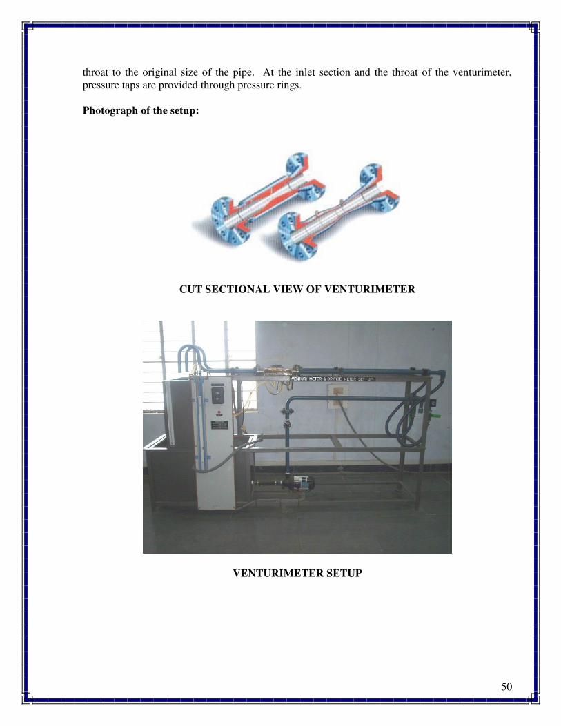
Photograph of the setup:
CUT SECTIONAL VIEW OF VENTURIMETER
VENTURIMETER SETUP
51
Procedure:
All the necessary instrumentations along with its accessories are readily connected. It is
just enough to follow the instructions below:
1. Fill in the sump tank with clean water.
2. Keep the delivery valve closed.
3. Connect the power cable to 1 Ph, 220 V, 10 Amps with earth connection.
4. Switch ON the pump and open the delivery valve.
5. Open the corresponding ball valve of the venturimeter pipe, keeping the valve of
orificemeter closed.
6. Adjust the flow through the control valve of the pump.
7. Open the corresponding ball valves fitted to venturimeter tappings.
8. Expel if any air is there by opening the drain cocks provided with the manometer and
note down the differential head reading in the manometer.
9. Close the Butterfly Valve of the collecting tank and note down the time taken for 20 c.m.
rise of water level
10. Keep the butterfly valve open when the readings are not taken.
11. Change the flow rate and repeat the steps 6 to 9 for 10 different flow rates.
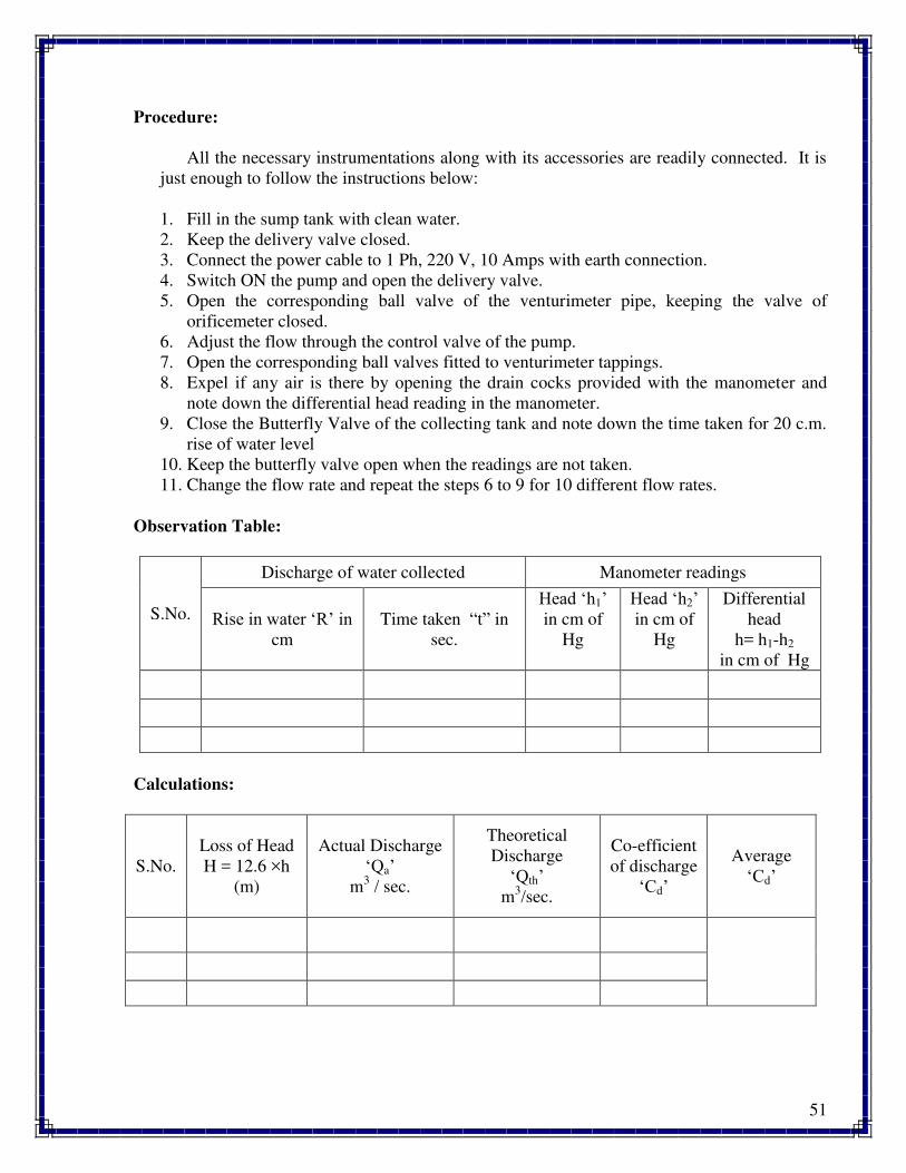
Observation Table:
S.No.
Discharge of water collected Manometer readings
Rise in water ‘R’ in cm
Time taken “t” in
sec.
Head ‘h1’ in cm of
Hg
Head ‘h2’ in cm of
Hg
Differential
head
h= h1-h2
in cm of Hg
Calculations:
S.No.
Loss of Head
H = 12.6 ×h
(m)
Actual Discharge
‘Qa’ m
3 / sec.
Theoretical
Discharge
‘Qth’ m
3/sec.
Co-efficient
of discharge
‘Cd’
Average
‘Cd’
52
Data:
Area of measuring tank “A” = 0.12 m2
Acceleration due to gravity, “g” = 9.81 m / sec2
Diameter of the venturimeter (throat), “d” = 12.5 mm
Diameter of the Inlet pipe of Venturimeter, “D” = 25 mm
Formulae:
1. Theoretical Discharge:
/Secm
aa
2gHaaQ 3
22
21
21th
where, a1 = area of inlet section of venturimeter = (πD2 / 4) m
2
a2 = area of throat of venturimeter = (πd2 / 4) m
2
2. Actual Discharge:
/Secmt
RAQ 3
a
where, A = Area of measuring tank in m2
R = Rise of water level in m.
t = time taken for rise of water level in sec.
3. Co - efficient of Discharge:
th
ad
Q
Q
dischargelTheoretica
dischargeActualC
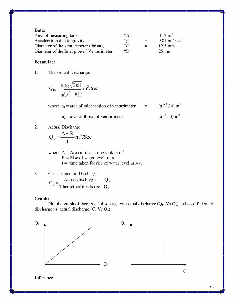
Graph:
Plot the graph of theoretical discharge vs. actual discharge (Qth Vs Qa) and co-efficient of
discharge vs. actual discharge (Cd Vs Qa).
Inference:
Qth
Qa
Qa
Cd
53
Precautions:
1. Do not start the pump if the voltage is less than 180 V.
2. Do not forget to give electrical neutral & earth connections correctly.
3. There is no danger of water being not there in the sump tank, since the measuring tank is
fitted with overflow pipe.
4. Frequently (at least once in three months) grease / oil the rotating parts.
5. Initially, put clean water free from foreign material, and change once in three months.
6. At least every week, operate the unit for five minutes to prevent clogging of the moving
parts.
Trouble shooting:
S.No. Problem Remedy
1. Unsteady manometer reading Remove the air bubbles by opening
the drain cock.
2. Pump not working Prime the pump
Result /Conclusion:
The average co-efficient of discharge was calculated and found out to be _______.
Extension:
Applications:
They are found in many applications where the discharge and velocity of the fluid are
important, and form the basis of devices like a carburetor.
Venturimeter is also used to measure the velocity of a fluid, by measuring pressure
changes from one point to another along the venturimeter. Placing a liquid in a U-shaped tube
and connecting the ends of the tubes to both ends of a venturimeter is all that is needed. When
the fluid flows though the venturimeter the pressure in the two ends of the tube will differ,
forcing the liquid to the "low pressure" side. The amount of that move can be calibrated to the
speed of the fluid flow.
Questions:
1. What is the main aim of the experiment?
2. What is the working principle of a venturimeter?
3. What are the sections of a venturimeter?
4. What are the losses on account of flow through a venturimeter?
5. What is the normal co-efficient of discharge in a venturimeter?
6. What are the precautions to be taken while performing the experiment?
54
Experiment No. 8
CALIBRATION OF ORIFICEMETER
Aim:
To demonstrate the use of orificemeter as flow meter and to determine the co-efficient of
discharge in closed conduit or pipe flows. Also to plot the graph of theoretical discharge vs.
actual discharge (Qth Vs Qa) and co-efficient of discharge vs. actual discharge (Cd Vs Qa).
Apparatus Required:
1. A constant steady supply of water with a means of varying the flow rate using monoblock
pump.
3. A pipe line fitted with a orificemeter.
4. Measuring tank to measure the flow rate.
5. Tappings with ball valves are provided at inlet and outlet of orificemeter and these are
connected to differential manometer.
6. Electronic digital timer with float switch for measurement of flow rate by collecting fixed
quantity of water.
Specifications:
1. Supply pipe of ø 21 mm (3/4") connected to inlet manifold.
2. Orifice meter size inlet ø 20 mm and throat ø 14 mm
3. Differential mercury manometer tapings provided at inlet and throat of orificemeter and
orifice meter. Manometer size 50 cm height.
4. Measuring tank size - 300 mm x 300 mm x 300 mm height.
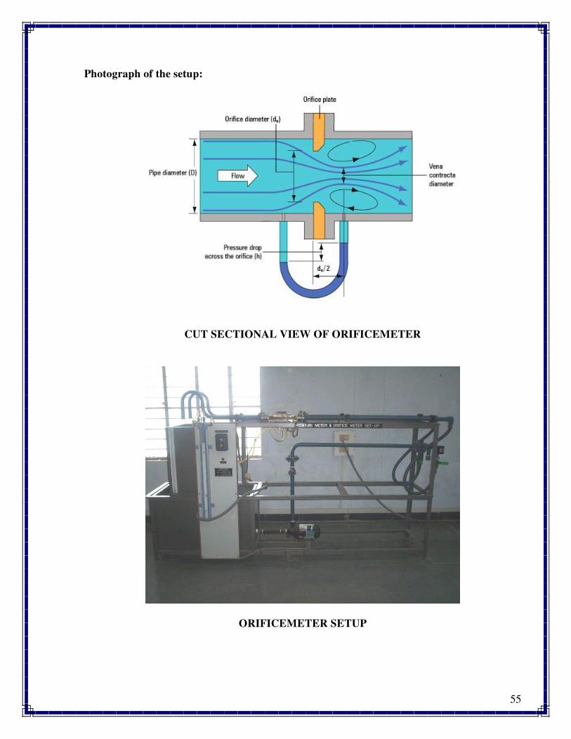
Theory:
An ORIFICE METER is another simple device used for measuring the discharge through
pipes. Orifice meter also works on the same principle as that of venturimeter i.e., by reducing the
cross-sectional area of the flow passage, a pressure difference between the two sections before
and after orifice is developed and the measurement of the pressure difference enables the
determination of the discharge through the pipe. However, an orifice meter is a cheaper
arrangement for discharge measurement through pipes and its installation requires a smaller
length as compared with venturimeter. As such where the space is limited, the orificemeter may
be used for the measurement of discharge through pipes.
55
Photograph of the setup:
CUT SECTIONAL VIEW OF ORIFICEMETER
ORIFICEMETER SETUP
56
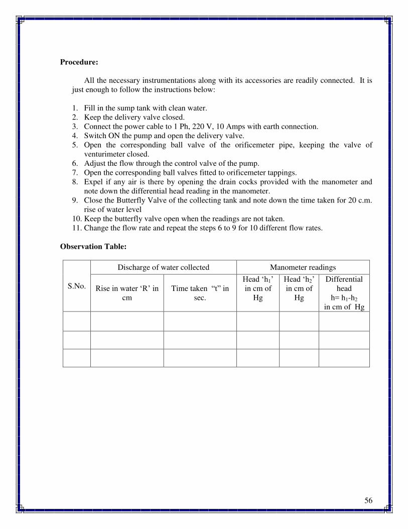
Procedure:
All the necessary instrumentations along with its accessories are readily connected. It is
just enough to follow the instructions below:
1. Fill in the sump tank with clean water.
2. Keep the delivery valve closed.
3. Connect the power cable to 1 Ph, 220 V, 10 Amps with earth connection.
4. Switch ON the pump and open the delivery valve.
5. Open the corresponding ball valve of the orificemeter pipe, keeping the valve of
venturimeter closed.
6. Adjust the flow through the control valve of the pump.
7. Open the corresponding ball valves fitted to orificemeter tappings.
8. Expel if any air is there by opening the drain cocks provided with the manometer and
note down the differential head reading in the manometer.
9. Close the Butterfly Valve of the collecting tank and note down the time taken for 20 c.m.
rise of water level
10. Keep the butterfly valve open when the readings are not taken.
11. Change the flow rate and repeat the steps 6 to 9 for 10 different flow rates.
Observation Table:
S.No.
Discharge of water collected Manometer readings
Rise in water ‘R’ in cm
Time taken “t” in
sec.
Head ‘h1’ in cm of
Hg
Head ‘h2’ in cm of
Hg
Differential
head
h= h1-h2
in cm of Hg
57
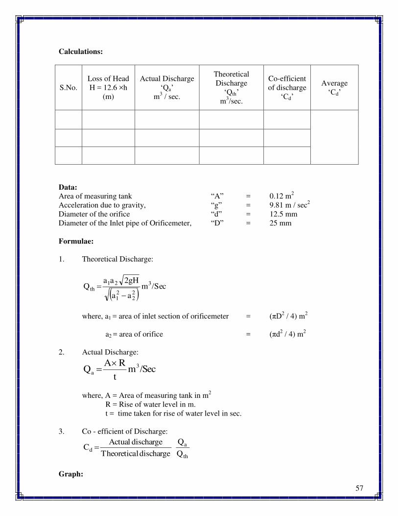
Calculations:
S.No.
Loss of Head
H = 12.6 ×h
(m)
Actual Discharge
‘Qa’ m
3 / sec.
Theoretical
Discharge
‘Qth’ m
3/sec.
Co-efficient
of discharge
‘Cd’
Average
‘Cd’
Data:
Area of measuring tank “A” = 0.12 m2
Acceleration due to gravity, “g” = 9.81 m / sec2
Diameter of the orifice “d” = 12.5 mm
Diameter of the Inlet pipe of Orificemeter, “D” = 25 mm
Formulae:
1. Theoretical Discharge:
/Secm
aa
2gHaaQ 3
22
21
21th
where, a1 = area of inlet section of orificemeter = (πD2 / 4) m
2
a2 = area of orifice = (πd2 / 4) m
2
2. Actual Discharge:
/Secmt
RAQ 3
a
where, A = Area of measuring tank in m2
R = Rise of water level in m.
t = time taken for rise of water level in sec.
3. Co - efficient of Discharge:
th
ad
Q
Q
dischargelTheoretica
dischargeActualC
Graph:
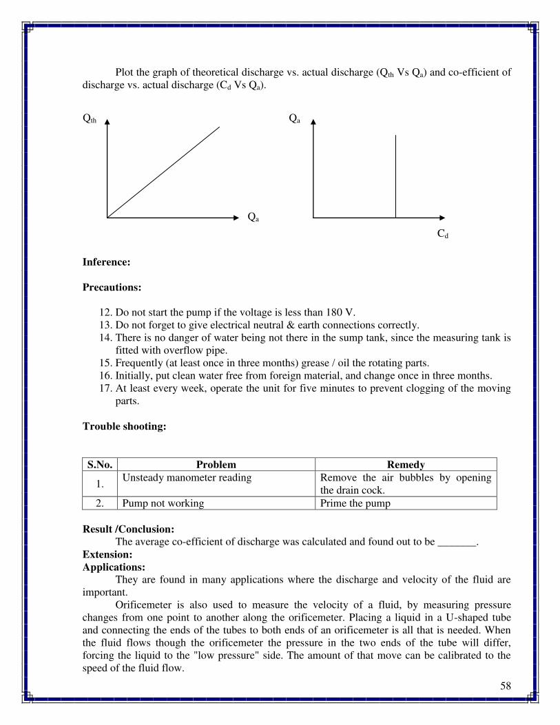
58
Plot the graph of theoretical discharge vs. actual discharge (Qth Vs Qa) and co-efficient of
discharge vs. actual discharge (Cd Vs Qa).
Inference:
Precautions:
12. Do not start the pump if the voltage is less than 180 V.
13. Do not forget to give electrical neutral & earth connections correctly.
14. There is no danger of water being not there in the sump tank, since the measuring tank is
fitted with overflow pipe.
15. Frequently (at least once in three months) grease / oil the rotating parts.
16. Initially, put clean water free from foreign material, and change once in three months.
17. At least every week, operate the unit for five minutes to prevent clogging of the moving
parts.
Trouble shooting:
S.No. Problem Remedy
1. Unsteady manometer reading Remove the air bubbles by opening
the drain cock.
2. Pump not working Prime the pump
Result /Conclusion:
The average co-efficient of discharge was calculated and found out to be _______.
Extension:
Applications:
They are found in many applications where the discharge and velocity of the fluid are
important.
Orificemeter is also used to measure the velocity of a fluid, by measuring pressure
changes from one point to another along the orificemeter. Placing a liquid in a U-shaped tube
and connecting the ends of the tubes to both ends of an orificemeter is all that is needed. When
the fluid flows though the orificemeter the pressure in the two ends of the tube will differ,
forcing the liquid to the "low pressure" side. The amount of that move can be calibrated to the
speed of the fluid flow.
Qth
Qa
Qa
Cd

59
Questions:
1. What is the main aim of the experiment?
2. What is the working principle of an orificemeter?
3. What are the sections of an orificemeter?
4. What are the losses on account of flow through an orificemeter?
5. What is the normal co-efficient of discharge in an orificemeter?
6. What are the precautions to be taken while performing the experiment?
60
Experiment No. 9
CALIBRATION OF NOTCH
Aim:
To calibrate the given V-notch, Trapezoidal and Rectangular notches by establishing the
relationship between the flow rate and the head over notches
Apparatus Required:
Notch apparatus, stop watch.
.
Specifications:
1. An approach channel a with baffle plates in it and fitted with a notch.
2. A surface level gauge (hook gauge) to measure the head over notches.
3. A constant steady supply of water with a means of varying the flow rate using centrifugal
pump.
4. Measuring tank to measure the flow rate.
Theory:
A notch may defined as a sharp edged obstruction over which flow of liquid occurs .The
sheet of water discharged by a notch is called “ Nappe or Vein” . Notches are used for measuring
the flow of water in open channel flow as in reservoirs and are generally rectangular, trapezoidal
or triangular in shape.
a) V- Notch:
Theoretical discharge:
Qth = (8/1η) √[2 g tan( /2)] H5/2 m
3/sec
Coefficient of Discharge,
C d = (Q a / Q t)
Where ‘H’ is the height of water surface above the apex of the notch , ( /2) is the half the notch angle and ‘C d’ is the coefficient of discharge. The value of Cd with different heads will be
almost constant. The value of Cd varies from 0.59 to 0.62, depending upon the dimensions of
notch.
b. Rectangular notch,
Theoretical discharge:
Qt = (2/3) b √(2 g) H3/2
where, ‘b’ = Width of Notch. Coefficient of Discharge,
C d = (Q a / Q t)
Photograph of the setup:
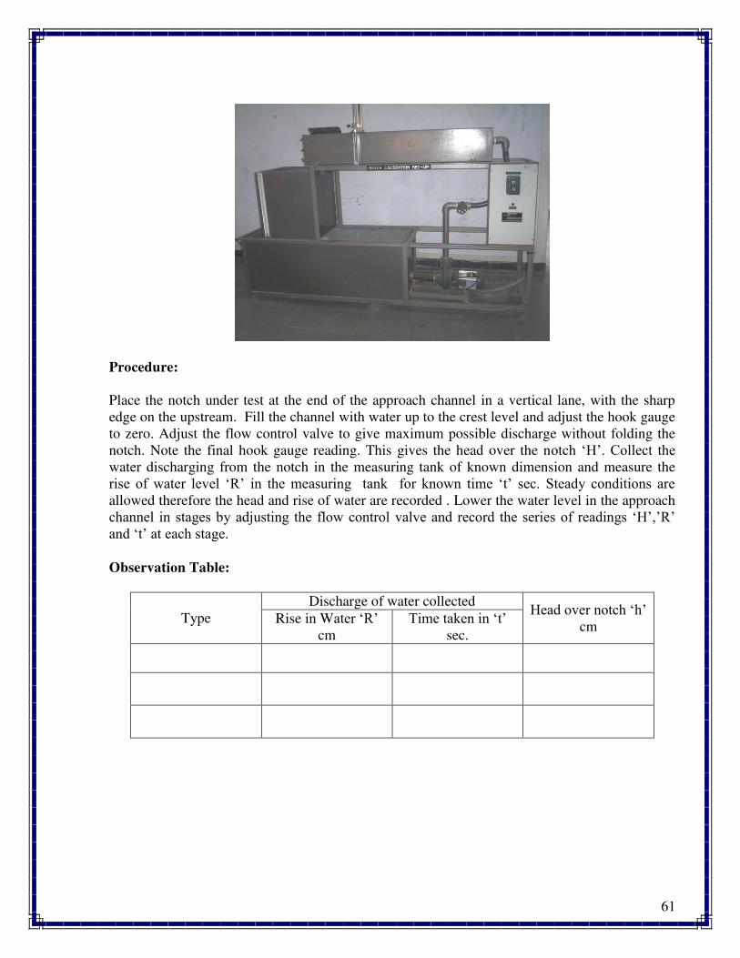
61
Procedure:
Place the notch under test at the end of the approach channel in a vertical lane, with the sharp
edge on the upstream. Fill the channel with water up to the crest level and adjust the hook gauge
to zero. Adjust the flow control valve to give maximum possible discharge without folding the
notch. Note the final hook gauge reading. This gives the head over the notch ‘H’. Collect the water discharging from the notch in the measuring tank of known dimension and measure the
rise of water level ‘R’ in the measuring tank for known time ‘t’ sec. Steady conditions are allowed therefore the head and rise of water are recorded . Lower the water level in the approach
channel in stages by adjusting the flow control valve and record the series of readings ‘H’,’R’ and ‘t’ at each stage.
Observation Table:
Type
Discharge of water collected Head over notch ‘h’ cm
Rise in Water ‘R’ cm
Time taken in ‘t’ sec.
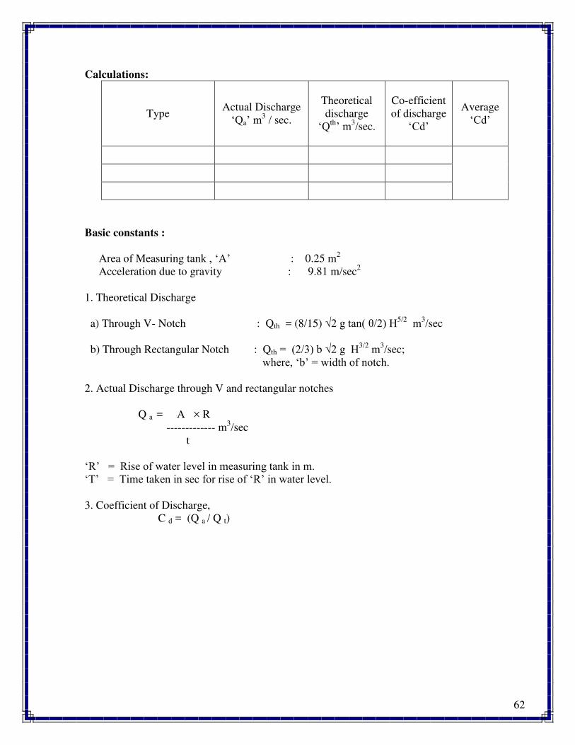
62
Calculations:
Type Actual Discharge
‘Qa’ m3 / sec.
Theoretical
discharge
‘Qth’ m3/sec.
Co-efficient
of discharge
‘Cd’
Average
‘Cd’
Basic constants :
Area of Measuring tank , ‘A’ : 0.25 m2
Acceleration due to gravity : 9.81 m/sec2
1. Theoretical Discharge
a) Through V- Notch : Qth = (8/15) √2 g tan( /2) H5/2 m
3/sec
b) Through Rectangular Notch : Qth = (2/3) b √2 g H3/2 m
3/sec;
where, ‘b’ = width of notch.
2. Actual Discharge through V and rectangular notches
Q a = A × R
------------- m3/sec
t
‘R’ = Rise of water level in measuring tank in m. ‘T’ = Time taken in sec for rise of ‘R’ in water level.
3. Coefficient of Discharge,
C d = (Q a / Q t)
63
Graph:
Plot the graph of theoretical discharge vs. actual discharge (Qth Vs Qa) and co-efficient of
discharge vs. actual discharge (Cd Vs Qa).
Inference:
Precautions:
1. Do not start the pump if the voltage is less than 180 V.
2. Do not forget to give electrical neutral & earth connections correctly.
3. There is no danger of water being not there in the sump tank, since the measuring tank is
fitted with overflow pipe.
4. Frequently (at least once in three months) grease / oil the rotating parts.
5. Initially, put clean water free from foreign material, and change once in three months.
6. At least every week, operate the unit for five minutes to prevent clogging of the moving
parts.
Trouble shooting:
S.No. Problem Remedy
1. Fluctuating Piezo meter reading Remove the air bubbles.
2. Pump not working Prime the pump
Result /Conclusion:
The average co-efficient of discharge was calculated and found out to be
i) for V-notch_______.
ii) for rectangular notch_______.
Extension:
Applications:
Used to measure the flow rate in open channel flows.
Questions:
1. What are the different types of notches?
2. What is the top layer of water called in a notch?
3. What is the bottom portion of a notch called?
4. What are the losses occurring in a notch?
5. Differentiate between notches, and venturimeter and orifice meter.
Qth
Qa
Qa
Cd
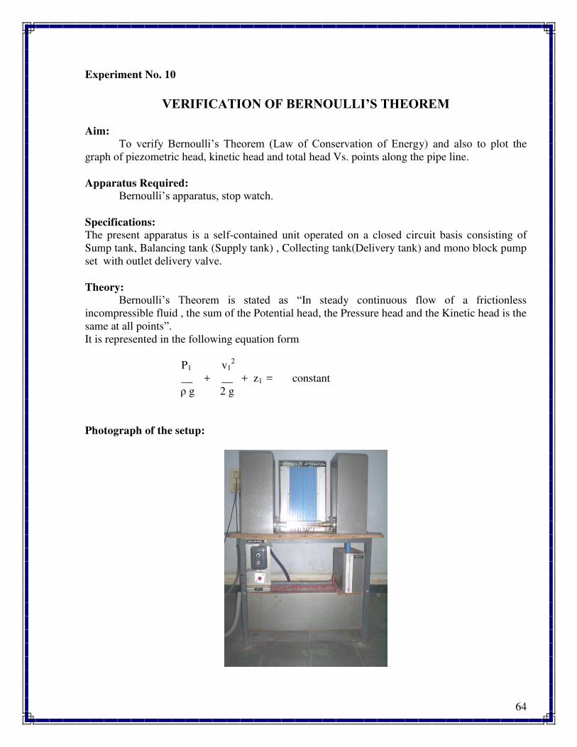
64
Experiment No. 10
VERIFICATION OF BERNOULLI’S THEOREM
Aim:
To verify Bernoulli’s Theorem (Law of Conservation of Energy) and also to plot the
graph of piezometric head, kinetic head and total head Vs. points along the pipe line.
Apparatus Required:
Bernoulli’s apparatus, stop watch.
Specifications:
The present apparatus is a self-contained unit operated on a closed circuit basis consisting of
Sump tank, Balancing tank (Supply tank) , Collecting tank(Delivery tank) and mono block pump
set with outlet delivery valve.
Theory:
Bernoulli’s Theorem is stated as “In steady continuous flow of a frictionless
incompressible fluid , the sum of the Potential head, the Pressure head and the Kinetic head is the
same at all points”.
It is represented in the following equation form
P1 v12
__ + __ + z1 = constant
ρ g 2 g
Photograph of the setup:
65
Procedure:
1. Fill in the Sump tank with clean water and add some quantity of colored ink to it.
2. Keep the delivery valve open.
3. Connect the power cable to 1 ph , 220V 10 amps with neutral and earth connections.
4. Switch on the pump. Now, you will find water flowing to the Collecting tank through
venturimeter.
5. Now you find the different piezometric heads for corresponding points of venturimeter
for constant supply head and delivery head.
6. Note down all the piezometric readings and velocity head at a particular is also noted
separately by bringing the inserted to that point.
7. Note down the height of water at supply tank and delivery tank.
8. Change the delivery head by pushing down the overflow pipe and repeat the experiment.
9. Also, change flow rate and repeat the experiment.
Observation Table:
Piezometer reading at
points
Diameter of Pipe
cm
Supply tank water
height
cm
Delivery tank water
height
cm
1
2
10
Calculations:
Points in
pipe
Piezometer
reading at
points
Area of
pipe
m2
Velocity of
flow
V=Q/A
m/s
Velocity head
V2
/2g
Total Head=
Piezometric +
velocity head
1
2
10
Graph:
Plot the graph of piezometric head, kinetic head and total head Vs. points along the pipe line.
66
Inference:
Precautions:
7. Do not start the pump if the voltage is less than 180 V.
8. Do not forget to give electrical neutral & earth connections correctly.
9. Frequently (at least once in three months) grease / oil the rotating parts.
10. Initially, put clean water free from foreign material, and change once in three months.
11. At least every week, operate the unit for five minutes to prevent clogging of the moving
parts.
Trouble shooting:
S.No. Problem Remedy
1. Fluctuating Piezo meter reading Remove the air bubbles.
2. Pump not working Prime the pump
Result /Conclusion:
The Bernoulli’s equation was verified by plotting the graph for HGL and TEL
Extension:
Applications:
.
Questions:
1. What is meant by the term pressure head?
2. State the law of conservation of energy.
3. Write down Bernoulli’s equation and explain the meaning of each term involved in it.
4. Write down the Bernoulli’s equation for real fluids.


