COMMONWEALTH OF AUSTRALIA. DEPARTMENT OF SUPPLY AND SHIPPING. MINERAL RESOURCES SURVEY. REPORT. No. -~w.+/t . r' (plans No. 1029-3032 1 . REPORT ON'. RESISTIVITY SURVEYS, LEETON-NARRANDERA DISTRICTS., N. SO We 13:. CANBERRA. 28th March9 1g&. By Authority : L. I?. JoHNBTON, Commonwealth Government Prluter, Cnuberra.
Transcript
COMMONWEALTH OF AUSTRALIA.
DEPARTMENT OF SUPPLY AND SHIPPING.
MINERAL RESOURCES SURVEY.
REPORT. No. - ~ w . + / t . r'
(plans No. 1029-3032 1.
REPORT ON'.
RESISTIVITY SURVEYS, LEETON-NARRANDERA DISTRICTS., N. SO W e
13:. CANBERRA. 28th March9 1g&.
By Authority : L. I?. JoHNBTON, Commonwealth Government Prluter, Cnuberra.
DEPART1,BNT OF SUPPLY AND SHIPPING, -. ' -\?D-1
EINEPJ& REgPURCES SURVEY* r.Cn=-LuDrn-rLS-
( ~ c g o ~ a t 1ToC 1944/7, Plans N o s c 1029-1032)
.F!.E8ISTIVITY .SUR'iT'YS, UETOX-NARRANDERA DISTRICTS, N. S .We u-I-.--i-UrCbPnbsh - ,... - '
RESISTIVITY SURVEYS, LEETON-NARRANDERA DISTRICTS9 NeSeVfe --....h.rOlD..IC--- U
Table of C o n t e n , , .-I
PART I - Tracing of Sand D r i f t s a t Leeton.
Introduction The Problem Technical Considerat ions F ie ld Work Discussion of Results Conclusions
PART I1 -- Applica.Lion '0.3 Res i s t i v i t y Pdethod~ t o the Determinatiol? of Sub-Surface Conditions a t Narranders
Introduction The Problem Technical Considerat ions F ie ld qork Discuasicn of Resv-1-Ls Conc1.u~ ions
P la te 1, Plan of Five Bridges Arca, Leeton, Nevi South Wales, showing posi t ions of r c s i s t i v i t y s t a t i o n s and bores.
Sections through s t a t i o n s and bores.
Locali ty Plan,
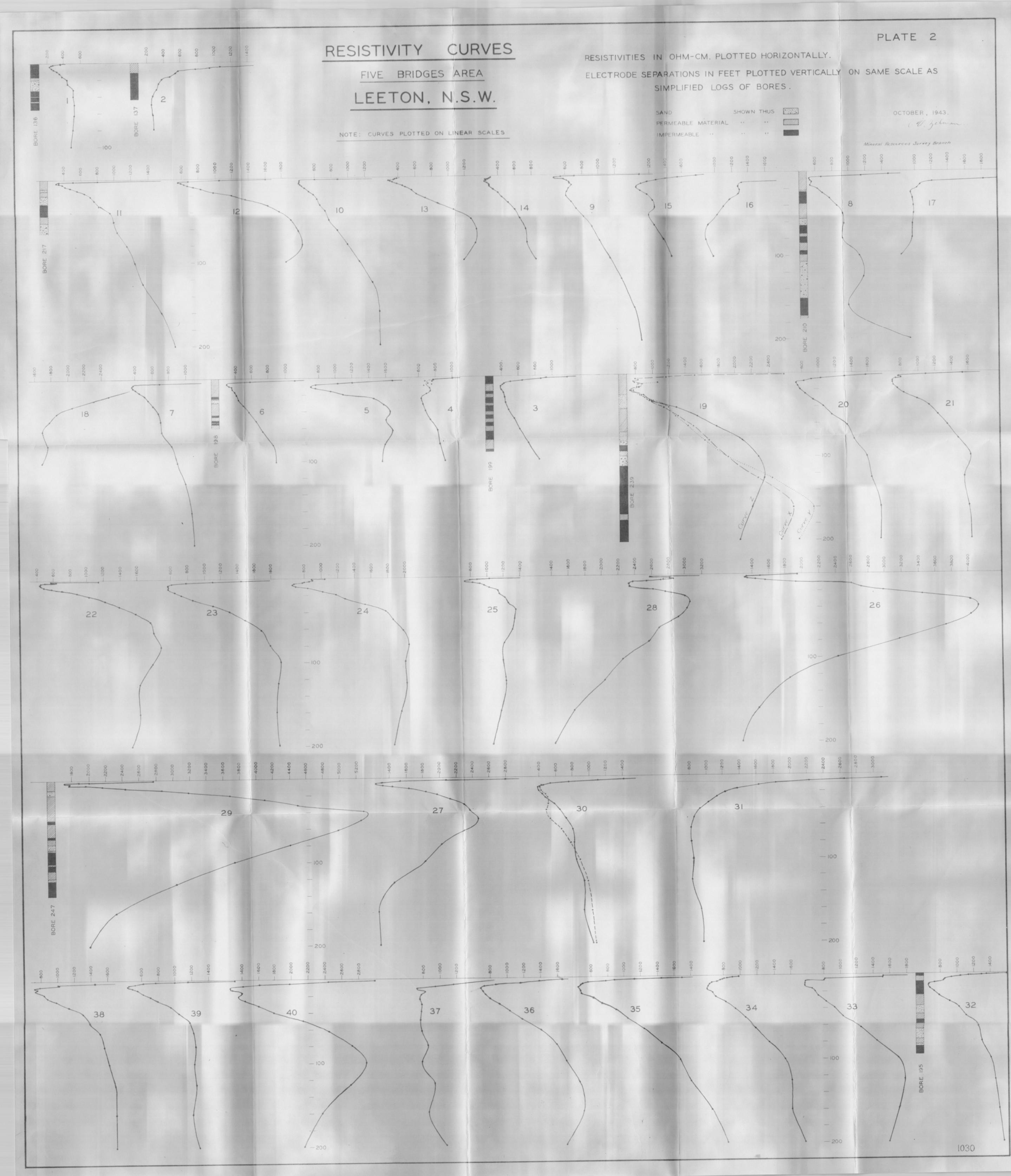
P la tc 2, Reois t iv i ty Curves (on l i n e a r ocalcs) Five Bridges Arca, with gmcra l i scd logs of bores,
Pla te 3. Plan of 9andhi.11~ Area, Narrmdera, New South Wales, showing posi t ions of r e s i s t i v i t y s t a t i o n s and bores.
Sections through s t a t ions and bore's.
Plat.tc 4.' Res is t iv i ty Curves (on log log scales) , Narrandera Sandhills Area, with general ised logs of b.ores.
WSISTIYITY SURVEYS 8 . ' :''<; ( i, .? f
IXETON-NLRRANDERA DISTRICT , N. 9 . W . - -- The f i r s t part of t h i s report deals with the second p h a ~ e
of the geophy~ical t e a t 5.~0rk carried out i n connection with thc invest.igat ions into the water seepage problems a t Leeton on tho Murnumbidgee I r r iga t ion .i&ea, The or ig ina l t e s t work was carr igd out by M r b J a M a R c L ; v ~ ~ , -:hen of the Nevr Soukh' Wales Mines' Department, following a request by thc VlJater Conservat ion and I r r iga t ion Commission, The wo~k described herein may be considered a s an c.xtension of tha t doni: by Mro Rayner and .it . w i l l be asswcd tha t , the reader has acccse t o h i s report racing of Smd Drifts a t Lccton by Geophysical Mepi;hods I:,,
The aecond. :?art of t h i s report deals with @;eophysica,l +;ect work on a sanLh:!.ll area a t Narrandera where it i s proposed t o ectabl lsh c i t ru r~ f a-mo using apray f r r iga t ion,
T h ~ o u g ~ ~ . L 'the r:urvcyo, the Watcr Conservation and I r r iga t ion Comnuiss9oli made available a s a i s t m t s and transport. Also it i s desired .Lo acknowledge gratef'ully the co-operation 2nd ass i s tmce o t t he \Manager and s t a f f at the om mission^ a T,ecton Office, e s p c c i n l l ~ the Research Officer, M r , H.N, England.
& U A I t ~ ~ z - u , ~ u i n ~ of&nd D r a f t s a t Leetor),
. - I n recentl yc)ars much. trouble has been experimed a t ~.:3e.f;on omring t o secZ,eg3 ~ i l d water logging, This water logging i s l .~ l iev .ed t o be duc t c lar?ge quant i t ies of water such as are used
, :In r ice f i e l d s , ooaki ??g through t he surface s o i l s into sand d r i f t o ' ~-1?.ich. underlicr: scma p2.r.i;~ of the area, These sand drifts enable the aa ter . t o 'tra-is-i.. +,r? o$her pa r t s of the a rea and sometimes ~ a i s e the ground w:.::;e:? l eve l t o such an extent tha t f r u i t t r e e s are lsilledo
The resea::ch. !.chaff o f the Water Conservation and Ir; x:igation Commission. h.ss dme much work investigating t h i s r,.?o5lem and many bores have been put down, One of the objects af t h i s boring i s i;o mask the limits of the sand drift areaB,
. . bx1.t the work has sho~:rii 'i;liat the sand i s far more extensive than ,i.;~;las supposed a t firs?;, cc that a very Large number of bores ~ ~ ~ u l d be necessary .Lo dsfine such areasa To reduce the number v?? bores required, a geog'hynical method has k e n applied and :~esul.ts show tha t sanJ d r i f t s can be generally located by t h i s ine am,
I n h i s report:, referred t o previously, M r . Rayner haa. c ~ ? out the proble1-n. and has.described the method adopted. E.imilar instruments and f i e l d technique were used, although the ltlj!.eggerlt instrument. -.:as not used a s its range ar@ accuracy were n u t suf$ieien-h for the wider electrode separations used i n the iiivestigation,
The irr).gxi:sr? area a t Leeton i s an old flood p la in of h e Mqmznbidgee Rive?,. A typical v e r t i c a l section, a s shown by boring, consietqa o f :iu-rface s o i l s res t ing on wet clays, then. loams and clays, Lhen heavy clays or pipe clays overlying artcs- ian sands ' a d gravels, which i n turn r e s t on a sandstone bedrockd I n places, sand dr?.f'is of various thiclmesses are found within the clays and loans, E w l i e r it was thought that there was only one layer o f sand, T~v.6 deeper boring has shown that there a re commonly two o r thrze sand layers*
i - 2 -
' . xhe Problem.
. . . . I . , ' .:,.: ,, .. . .
'c, : , , . . - .... Tho problem t h e n ) 1 ~ . t o ' locn tc those sand d r i f t s
beneath the surface, and t 4 do oo wi$h gpecd and reasonable certainty, so t ha t only occasional bores nee2 be put down f o r confirination of the goophyaical vforlc, and f o r the moasuPehcnt - . _. ,..._4 Y.-..,. o$,:.ground . . water levels ,
.... J ,. .... ...
~ e 6 h n i ~ a l Considerations. - . , , . .
. Tho r e s i s t i v i t y apparatus used i n thc survcy consisted o f the f oliovfing items,
B d i r e c t currenl; ,supply Prom a number of h e a h duty 45 vol t dry ce l l s , , .
a . . .
An jnsfrumont f o r control l ing and meacbring t h i s currcntb
A sens i t ive Do Cd potent lometer f o r measuring po ten t i a l .dif Fere'nco, . ,
A sens i t ive galvanometer f o r use with tho D.C. potentiornctor. '
* 3 t e e l spilres f o r curren-1; olectrodesa
Porons pots with inner copper electrodes and f i l l e d with copper aulphate so lu t ion f o r non-polarizing potol l t ial cloctrodos,
Cable f o r coluicc~tionc.
During a survcy, four e lec t rodes a re used t o make contnct with the ground. Tlicy arc placed i n a s t r a igh t l i n e and spaced equally with the centre of t h c syotum above %.he pcg n~arking the 8 6 c t i o h This irralgerilcnt is lcnown a s the Wenncr configuration and i!3 shown d i a g r m a t i c a l l y i n f igurc 1.
(11111----1t 1 . +
E 1
a- . r . I Q. L / - a G,-ouwd Surfat- a * 9 --. ' - 2
rc
I-
FIG. 1
A mensurcd current i s passcd through' the outer pa i r of e lec t rodes A.and D and t h e p o t e n t i a l difference across the inner electrodes B nnd C is measured. Tho r e s i s t i v i t y , i n ohm cm. is t.hen obkained from tho formula -
E - . gotcnCLa2. dl.fferencc ?.n v . 0 1 3 ~ acres$. . .. the i n n c r 1 ,
e!.ectrodcsC, ' . : . ,. . , . . . 1 :. currenab i n a~.i-s .. 2nshing ' thr6ugh o k t c r ' electrod&s.~'
,;ach s~i;jZi.c;~--:.' pendG'r'6ment s',.arc comx nced with itetl :,pj.+e ~aal!. - say Pee.;:. .;. and , i.ncr 3ased by logar i thmic i n t e r - va.:!.~ .L!~..;;j,:.- sz).y9 !!aii - - , 230 '.ee.i; 9 and tho r e s i s t i v i t y i s g l o t t e 8 ag:xir,6-:; .tho s ipa ra t ion 5.n :?ec-L as i n f igure 2. 1% is usually n.or;z::su,::y Po:'. n~n;-pol:.~r;~.z:i..ne; electrodgs t o bc used a t B.. and C .ib:h,c1l .i;Ili: acpayn.bj.ol?. i;:. nj.Ti:?,? .!;hay1 a few f i e% ,,
. Bhc;r. 'che:;,scgar.c!-;ion 2.8 small the e f f ec t ive dspth of r,?nz.i;r!U;l.on oj: the cv.?rer~-k i s smal:l a l so and t h e ro s i s t i v i t y -
~~fiilwri:rt : i .c %ha-b of L l e juPf ncc and near surf ace materials. When ?;ap:lritbi,or, 'is ;.;lcredi:;od suf f i c i a n t l y f o r th6 currgnt $0, .pen-,
J . ,.c&o nor-,? imd.c:r&y;rS.ng mz:;cpial of d i f fe ren t r e s i s t i v i t y , thefi ' the i:9!,3'~D':ij.B~{;>- 1n~asureC .:;he ourficc: w i l l be a l t e r e d , . by . . tho presence
L I
f' IN OHM-CM. I 1 1 I 1
I- W W , CL
z - - . - . - - - - . . . - - -
tl CONDUCTIVE -
z o_ 2 - OC
b - W cn FIG. 2
L 3
. . I7igu.r~ 2 ~'Jon:: u r e s i s t i v i t y curve corresponding t o the
+;vfo ?.a>-er s c c t i o n ~ ~ ~ v o s : , I-i l.ii11 be noted t h a t f o r the smaller ~;cpnrs<; iona, is i ~ i g h , bcing .!;hat f o r t he upper r e s i s t i v e Layer, :Out ns ttn!: is incriast:d,, t h o offcci; of t h e conductive layer be-, ccmc:: up;?arcat, and i71heq the tij.clmess of the upl3cr layer i s srna:.l coinpared. t o t h o , s o ~ n r n - b i o n , t h e c - u r v e b s reached a steady Lori valve?, v~hlhich i s .;hc.; o f tha conductive lovrer layer. The ~,eparn.l;ion lfa!) fLn for?'; f:orrar:spondirig t o the point of ' in f lex ion i s of.i;en cnnpare.ble v~Fij.th $b depth i n f e e t t o the, in te r face , thus rri~5.n.g.. ,a. ~ p u g h ir@i cqt i ;>n of the t hickms s of the upper 1ayUr. L>
111 pr,aci.ica, howcirer, mdia ula1l.orate and r e l i u b l e n e t h o & a r e uooa fop abb%nicJ.ng the de:$th sf %he in te r face and t h e r e s i s t i v i t i e s of the t a b i & i e ~ ~ ~ . . , I
. . .. . . . _, ,
If ';here 1.8 a;:~,(,ther layer of r e s i s t i v e mater ia l below tho conch~c.Li.ro onc, t i lei RE 'kil.e separat ion is increased the curvc! tends t o swing back t o bi3.e rig]?<; hnfore 5.i; reaches i t s loviest
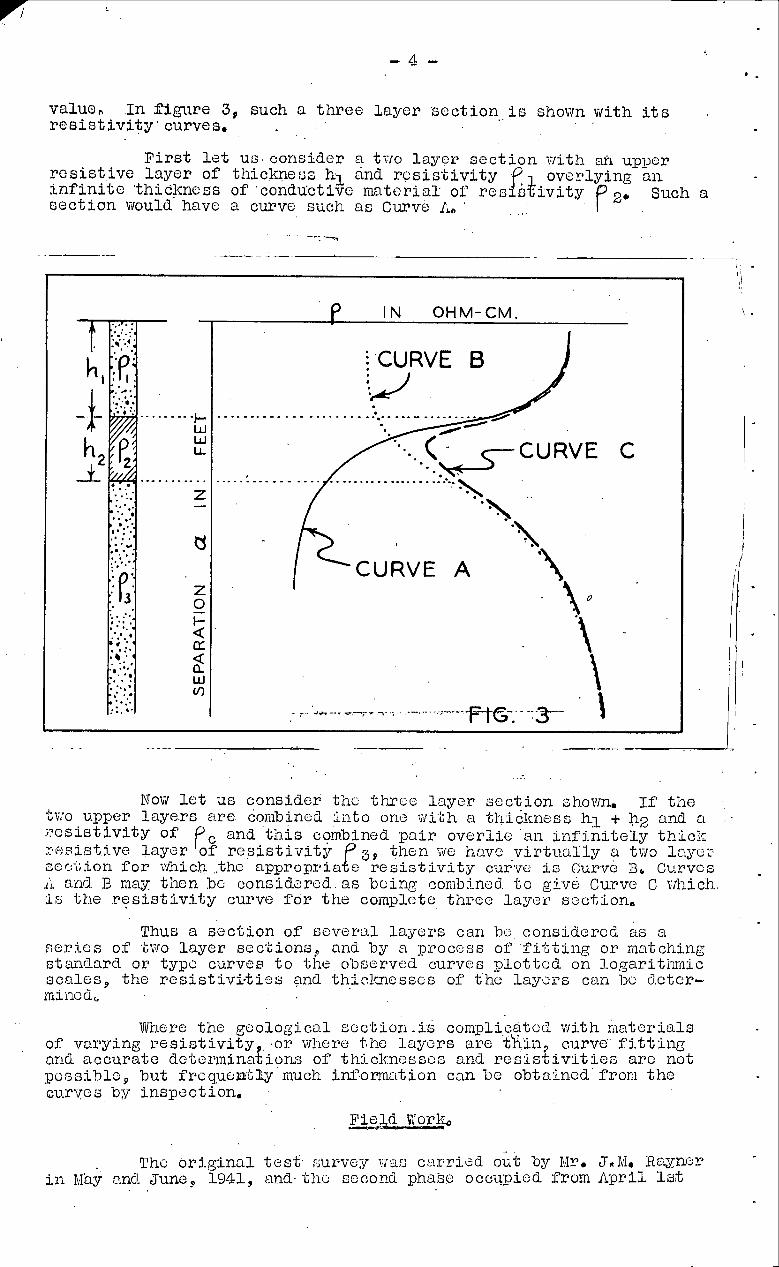
value, I n f igure 3, such a t h r e e Layer s o c t i o n , i c shovin with i t s r e s i s t i v i t y ' curves,
F i r s t l e t US corlsidcr ? two l a y c ~ ~ s e c t i o n I-lit11 ai upper r e s i s t i v e l a y e r of thiclmeuc hl and r c s i s t i v i t y o v e ~ l y i n g a n i n f i n i t e ~thicjmncss of .condactivc m a t e r i a l of r en rok iv i ty P 2*
Such a s e c t i o n would have a curve such as Curve fL, '
Now l e t u s consider' tile three l a y e r s e c t i o n shown, If tlze ' ~ W O upper 1 a y e . r ~ a r e cojnbined r i i~ to onc :;ii.Lh a thidlsliesc hl + h2 and a . ;?cs is t iv i ty of pc and t h i s cambined p a i r o v e r l i e an i n f i n i t e l y thiolr ? ~ L ! P ~ s ~ . ~ v R laye r of r e s i s t i v i t y s 9 then w e havc v i r t u a l l y a t w o lnyoz 3oc'l;ion f o r which ..the a p p r o p ~ i a P e r e s i s t i v i t y curve i s ~ u r v c Bo Curves .A and I? may: tlien bc: conaid?red.. as bcing conib3.ned. t o givk Cwve C vihich. ;is 1;he r e s i s t i v i t y curve f o r t h e colnplete t h r e e l a g e r scc t ion ,
Thus a sec-Lion o f s e v e r ~ . l l a y e r s can bc considcrcd as a se:r:ies of .i;v~o l a y e r sec'Lions, and by a procoss of f iJ6ti i ig o r ma'tchilig sts~ndnrd or typc curves t o tlie olicer.ved curves p l o t t c d on l o g a r i t i ~ ~ i i c scnles , the r e s i s t i v i - t i 2 s gnd thiclraesses of' t 'he l a y c r s can 1x2 detcr- miilcd,
VJ'here the goological scc.t ion .is con~pli,catccl with n n t e r i a l s of varying r e s i c t i v i t y , . o r where t.he 1-aycrs are t h ~ l i ~ curve, fi.ttil18 and accura te determinat ions of thiclcncssco and r e s i s t i v i t i e s arc not poss ih lc , but frcguonLliy much inCom;' i t ion can bc obtained' from thhe GU-rve s by inspoc t ion,
- The o r i g i n a l t e s t . survey viia:; carr ied. o ~ t by Mr. J*M, Rwncr
i n 1,Ihy and June? 1941, and. thc second pha$e occupied From A p r i l 13-b . .
tir hp'iil 19th and from J u m 23rBsto ~ u i ~ ' 1 2 t h , 1943, dn July l a t h , work was. commenced on. the sandhi l l a rea north of Narrandera. ' his
, work i s dea l t with An Par t 11, of .the , . : I
I n the above ge r iods , $40 ; ta t ions w6rq observed duririg. ,
184 days field work using f o r most' of them q crew consis t ina of '.' ' . the observer and two a s s i s t an t s , S ta t ions had t o be repeated occasionally and r a i n a l so caused delayo
. . For purposes of corsclat ion, observations wcrc. conmencecl on -i;v:o adjacent bore holes, sand. d r i f t being present i n one and abni:n'L i n the o t h e ~ , T h ~ s e bore ho'lcs, Nos, 136 and. 137, a r e about 2 mil-co north of Leeton,, u.t the southv~est and. southeast corners reni2cc':;j.vely of Porljion 90, Farm 136, and each i s about 6CI f'oct ilcep, M r c Na, , 136 ahowzd the presence of sand between 18 f o e t 33. fed; from the surface,, Theso s ta t ions , Nos, 1 and 2, wivere ob- re,r.ired with separations, up t o LOO f e e t , and the curves together -iil.th g ~ n e ~ a l i s c d logs of the bores a r e shown on p l a t e 2.
. 0b;servations wore made next on an area viherae water %.oggj.ng had alaxady occurred and where sl~al lom sand was known t o ex;i.s.:, The s t a t i o n NO,.^). first occupied is on thc Gogeldrie- M a c ~ q n i road, apprr?ximal;ely one m i l e north 'of the main .Leeton-. 8. . ,
'.A
G.r;i.Pf?.$h roado A bore had. been put down here and i t s log was :F'ou?nc:! . ~ e r y useful f o r cor re la t ion purposeso Further s t a t ions vre:.?? observed t o 2 miles south and. t o 3* m i l e s , north.., t h e i r :+oni.tions being shown ou; the p lan on g l a to 1;.
Discussion of Results, P I TI W - W
On p la t e 1, a plan of the area is shovin together ::oc-b:~o~~s along the l i n e s of borea and s ta t ions , I n these rnection.~ .::he 5.nfor::rns~t i c n from b o ~ e holec and from 'the obaervntions ha& bci3n cseG $0 show thc probable loca t ion of tho sand clrifts; It will llo :i.?o.i;2d from the scctj.on and. from thc curves, t Z d t h e southerii . 3cl>'t;i.i.cn cf thc north-.south l i n c is inorc disturbed than the northern ;?art where the driTi"'Ls car1 be t raced through Inore eas i ly , I't i s ~~~~~~Lunata t ha t t irric did not permit observing Inore st a t ions t o :?ill the gap between s t a t i ons No, 3 and Noo , 3.9? .
The curves p lo t ted from observations i n t h i s a r c a , a r e shokvn on p l a t e 2, They a re p lo t ted on l i n e a r scalcs, Whcre bores have becn p u t ; dovin thcj.r genaralisod logs have been p lo t t cd alongside -the appropriate curve s, I n general, t he dry 'surf ace mater ia ls show quite a high r e s i s t i v i t y of severa l thousand ohm ciq.,.?., Below t h i s there are wet clays whose . ~ ~ e s i s t i v i t y is, i n some
: places, a s low as 200, ohm. cm, Thc values f o r loams and l i g h t . '
' acnCy clays are between the values f o r surface s o i l and clays, ivhtle t h a t f o r sand i s . r e l a t i v e l y high, Thus a sarid. laycr,. un- :'Less very th in , w i l l show up i n the curve as a bulge towards a higher r e s i s % i v i t y o
Bore No, ' 136 shovis sand drif, : a t 19 f o c t t o 33 feet , , The ourvi: p lo t ted from observations at s-b, .';ion No. L.near t h i s 'bore shows a nmrkert bulge correaponding t o the sand d r i f t , Thc re:; heavy clay near tho surface has. a Ticry low y , the cu.rvo indicat ing P = 230 O I ~ I cm, at 4 f e e t separat iono Below the sanG -the , r e s i s t i .~ri- i ;y seems Lo l?e:~ch o bteady value of' ' about 500 ohm, , ,
cm, corresponding t o clays and heavy locuns, " ,.
Uorc No, 137 shows '11 f e e t of permeable rilaterials over- ly ing heavy or iliiperneablc clay,s t o the bottom of the hole a t 44 Pee.t, There i o no sand p ~ e b & r r b , - ~ . ~ h e curve at s t a t i o n Wo. 2
nhows higher values fo r the permeable mate r ia l quiclrly f a l l i n g away 40 low vdlue's about 300 01x1 c k , f o r the impermeable materials bel-ovm The curve i s smooth and novihore ollows a tendency t o bulgc +
t o higher /? which vfoulc? indicate sand .as in 'stution'No. 1.
I n the curves For s t a t i o n s Nos.11 and 8, the sand shown i n the bores corresponds with bulges i n the curves.* The correspondonce i s not 60 apparent i n No.6, but the sand layer i s no-i; very thick, The curve should be cornpared with t h a t f o r s t a t ion No, 3 vrhere bore Noa3L99 showed no sand, Between s t a t i o n s N o s r l L and 3, 16 s t a t i ons were ob- served, No observations s e r e made between s t a t i o n s Mo.3 and No.19 about a mile fu r the r north, S t a t i on No; 19 was observed and the curve X was plot ted , Then bore No,239 was sunk a t the same place aiid a simplified ver,sion of i t s log i s shown with the curve on p l a t e 2. Tho correspondence between curve X and' the log.1vas not good For the 1ov1:lar par t of the curve, and the observations"were repeated with an addition- a l s a t a t r i gh t angles, The curves are shown, and marked Y and Z respectively, It w i l l .be noted t h a t .curve Y which was observed with almost the same electrode posi t ions as curve X pese~nbles i t very close- ly , but curve Z, observed trvit l i the l i n e of e1oc'l;rodes a t r i g h t aliglea t o tha t used f o r X and Y, i s qui te d i f f e r en t , m d r e f l e c t s clo'sely the conditions found i n the bore, S t a t i on Nor 19 was near cross roads, with 5"ainage and supsly canals, power and telephone l i n e s and wire fenceb, Sofile of tbfoe ma,y have caused the difPereiic8 batweon the tv10 se t s of observations, a s boring and other eviddnce shosfi t h a t t h e various beds a re very clos'e -Lo horizontal ,
Bore No, 247 was put down nea r . s t a t i o n Ho.29 t o inves t iga te a.phenominally large bulge t o a very high r e s i s t i v i t y i n t h a t curve, This bulge i s evident i n the curves from s t a t i o n No,28, north t o s t a t i o n No-27, The bore log d i d izot explain f u l l y the i1eason f o r tlze extremely la rge , r e s i s t i v i t i e s observed, It is ulidarstood t h a t tho sand encountered between 11 f e e t and 17 f e e t during boring was dry and t h i s would have an extremely high r e s i s t i v i t y . Its thickness i s small. however, and would not be expected t o causc t'ne bulge where it occurrol. Available' empirical data have ilot ass i s ted great ly i n exL)lainiiig t h i s e f f ec t , although i t i s lrnown t h a t i n see-bions with extreiil~ rcsisLiv- i t i e s and t h i n layers , the usual solutioii of -bhrcc layer curves i s not possible,
The curve f o r s t a t i o n No, 30, does not show a bulge similar t o t h a t i n the curve f o r s t a t i o l i No.29, HOL-lever, soiile sand could bc dxyected a t t h i s placc. Tlie s t a t i o n was ~ e p e a t c d with thc a lec t rodcs l i ne a t r igh t angles a s thero WeTc p a r t l y buried )$ire netting fences near@. The two curves a re olloavn super ili~gosed,
S ta t ion No,31 vi:ras tlic farthe:, t north and -Lhe curve is a vcry smooth one v?t.hhout bulges. It indicates ail absents of s a i d d r i f t s .
Two short east-west l i ne s of s t a t i o n s were observed, Ono l i n c s t a r t e d at bore No,195 ( ~ t ~ t i o n ~ 0 ~ 3 2 ) and hem again the curve r e f l e c t s the conditions shown by the bore. S ta t ions viere observed a t half mile intervals west f o r tlwce miles, The l a s t s t a t i on , No.37, appears t o be on a place f r e e of sand d r i f t s , About two rrnriles north, another l i n e of throe s t a t i o n s was observed,
From a study of the curves, it ap:.cars t h a t sand drif'ts can usually be detected, although the thic-messes of the d r i f t s , t h e i r number and depths, a re not alvrays so readi ly sho~:~n. Tho abstlncc of sand 1s shown very clcarly. It i s unfortunate t h a t thc presence of a w r y t h i n U y e r of .iriipem~eable material, which l t i ~ u l d be cnough t o prevent surface water '.reaching a d p i f t , probably could not bc dcduced from the curves. -
It is considered t h a t the r e s i s t i v i t y method i s cui tabla f o r quick reconnaissance work, whereby the prosence of sand can ba shown, Boring. would be necessary t o check the gaophysical uorl; a t in loruals , a l so f o r the iilensuroiilent of ground water lcvols , but tho number of bores could be reduced considel~ably and others placed norc advantageously by uw of the xethod.
PART I1 - . AL&icat ion of Res i s t i v i t y Methods t o t ,he Determ~&t _U(- ion of-mace Conditions
- 4 , a 6 T E F a n fie r a ,, II--
' .
. . ( . . ' ' It is des i red ,by the Water Consecvat,ion. and I r r i g a t i o n 3onin1isskon t o open.up , a new citrus-gronilig area on the sandhi l l s north of Narrandera r a i l w w . s t a t i on , and t o 'the ea s t of *he na in
. . canaZc Spray i r r igat j .on w i l l ' b e used 'and vegktables w i l l b b e + . ' , . , r . .,. g:~'ovai be'tvfeen the ronu'- of cj-t-rus t r e e s tvhile the t r e e s ' a r e sl-imll. This a;7ea of about 3,000. acres . is f o r the most 'part undulating . with some lovi-lyj-ng f l a t s f r ec of sand,, l!Iuch,of the area has becri ciear'ed andl c~tlt ' ivated, Some i s . used 'for .'grazing,$ and a' l i t t , l e i s covered with li.gh't. scruh, . . . . . . . .
I I . ' . . . . . . . Thc sand h i l l s . in the a rea consist of wind-blown sand,
no\ir prevelite,d from f;u?.thcr rnovGmxcnt, by t r s e a 'and grassoo, There .a:.?e some sandstone ou.i;crops, The sect$on .revealed by one of' t h e . a
bores 2ut Lawn i n the .area showed sand overlying permeable loan^ , , . ,
a LrS! sandy clays, then .a considerable t h i cknes , so f a l l u v i a l m ~ t e r i a l s ' of varying cha;?acter, then: a l i t t l e c'and f e s t i n g on a r e l a t i ve ly impernieablc: lager of heavy clay. The bore d i d not ' .
reach sandctonec
It was decided t h a t some geophysical t e s t viorlc should be e.,ne on t h i s area ~115~ t h a t the r d c i s t i v i t y method be adopted. l!fhei~ geophysical vrork cocm need, no bores had been put down i n tl?c arcs, but a t the time of vjritil-@, tkrec bores bccn completed.
! '
Tlx. geop&sical problezl aao t o gn-ther sub-surface in-- formation t o a s s i s t i n forecasting the bokaviour of tlie watcr di-aining through thc s o i l & te r i r r i g r~ t ion . - It vac required t o f i nd , ii' possible, the thicltncss of sand and pemlcable niatcriala. ~ ~ o r n - th is- informa&,ion .the . sub-surf'abe contours of . 'kl~c. .ilnperme gble
. . . ~19teexiials m a y be ,..deteymincd, :, . ,
. 4
TecE-Lnical Conaiderations, . -.I-"-...--.---
. .
The apparatus and 'tkchnique outl incd i n Par t I of t h i s ~?eporS were used, Reqdings were t'dcen with. separat ions r mging fr.om. l& fee t . t o 200 .feet, It was found tha t the curves mere. re-
.r.larX;;abl;y smooth and. a s the work progressedib mjs pos.s.ible t o ;?i?ducc colmiderablQ- th.e n.u.riBe? of .ob se,rvat'ions a t each stxGi.~l?~ .
The range o f re sj.sbivj.tioc )?as .much la rger than i n the ~ e k t o n . , aze a. and. the iolies of d j f feren"i,re o i c t j.vit.ics were Inore c legr ly . :I-efincd, The curves were -gdot.ted 012 1ogarj:thrai.c s ca l e s and. ,d-epthg . .
.k,o the in ter faces determililned by thc: nethod OF fi.%tiizg t n d curveEd . . . . . , .
, F i e ld ~virork on the area . co~:lli;lence.d 012 July. 13th, and- con-- ~:::iuClcd on Av.[. .& 3rc1,;. I11 t h i s t inie' .417 a:t'a-i;i,.ons, y e 3% obgerved . .
during 3.2& clays f i e l d W O ~ B : , Th:i~ r a t e of r e a d i ~ ~ , . 3,7 station,^ per d . q y ! , was consicl~rably betL.or than tkii: r z t e o f 2.2 statiolzs
$. - per day obtained fit Leetonu About one t h i r d of ths s t a t i o n s a t Leeton were read t o 100 f e c t separation, tho romaindcr t o 200 f a c t , A l l Narrandera s t a t l o r n ijcre reail Lo,.20O fect . The speed of thc norlc wao affected by the c i rcu~is tances noted below. . .
I. A four th man was included i n the team. The observer read . :
the D r C I potentiornetcr and bookccl renaings. H i s first, a s s i s t a n t controlled the current and. e r e c t e d the other ' ,
two a s s i s t m t a vihcn moving electrodes, I
2, Some simplk devices wore u ~ c d t o nark the scparat lons at each s ta t ion,
30 Bo t t e r 'methodc of' handling cablos were bciployed,
4. Sta t ions vierc located on the 600 f e c t g r i d usecl by thc ~ o i ~ n i s c i o n ' s surveyor i n contouring the . areal .
5, ,The, ,nunb,er of observations a t each s t a t i o n was reduced;
6, The work was hampered by ra in , and occos$onally s ta t iono .had t o bo repeated a f t e r t h e equiprfient had dried.
, . -. -@:
7, T,ravelling t o and from the job used about 1& hours each day, . ,
A s the mount of time availnblw f o r the work vias l imited, it was decided 'to rend two l i n e s of s t a t i ons a t r i gh t angles and then addi t ional Li:nes a s time permitted.
The first s t a t i o n was read a t l i n e 11/6000 So wherc t h e sand- stone country rock outcropped, Sta t ions wers read every 600 f e e t aor th along l i n e 7 t o 7'/13000 N. where sandctone again outcropped. hn eaci.t-viest l i n e was ~ a 4 , a t 600 feet' ilztcrvals between s t a t i ons a t 4/1200 N , , and 10/1200 N, North-south l i n e s viere read n t '1200 f e e t i l ~ t e p v a l s along l inca 4 and 13, &ldit*o,ml stations'kvere read a& in- dicated 011 the plan shov~n on p l a t e 3. .
D f scuosion of Results.
The curvea from' observations 5n t h i s m c a , are p lo t t ed on logarithmic ~ c a l e ~ an& arc shown on p l a t e 4.
Thc curves show the smle form throughout and are character- ized by very high r e s i s t i v i t y , &n some ]?laces up t o 500,000 ohm cm* f o r the surface sands, then a l t e r i n g t o low values, i n some i3laces a s low a s 600 ohm crn. f o r t h e most conductive layers. The curves then trend towards higher values with increase of depth, a s the moderately roc i s t ive underlying mater ia l adds i t s effect .
Generalised logs of the t h ree bores con1pJeted a t the time of viriting ore shown on p l a t e 4. The curve f o r s t a t i o n 7/600 9. i s p lo t ted on l i neo r s ca l e s beside the log of bore No. 1. t
, , , , In most o f the curves, t h s l ayer of sand on the curface is
c lea r ly shourn, and can b e measured by using the type curves. LjIpwise, the most conductive layer . s h ~ s s . up and the depth can be dctermin~d.
No. 1 bore was put down on stationd:7/600 S. Frgn inspect ion of the curve and by f i t t i n g type curves, about 14 f e e t of sand was expected. Below t h i s , l e s s permcable m ~ . t e r i a l s were expected t o over#- l i e the inoct conductive layer a t 80 feet . Thc 'bore shovfed the expect- ed thickness of sand9 but t h e most conductive layer comes i n a sec t ion loggcd as having a varying permeability and occupzing from 44 f e e t t o 100 feet. Relat ively impermeable riiatcrial occurred a t 111 fee t .
. , . . ore ~ 1 . 2 vrnk ,$u'nk a b c u ~ j 200: ?&'6k' e n s t i of s t a g i d n . , ,
7/2400 S . Prom i n s ~ c d . l i on bf, the . ' ~&rve -at ,'7/3400 S.. ,, , 'about 5 fee-;; of highly r e s i s t i v e sand was'' expectea; birii ' the bore sl~oived , l 6 f e e t cl-assif ' ied, as. sand, . The m 0 s . t condu.ctive s e c t i o n i s shown by the curve to , be .a-t' about .90 ,f'get vrhich+.'is,'ne'ir; 't.he.+ :celitpe of the virater encountered i n "the bor6:;,.(59 f e e t ' -GO 118 . . f e e t , ) ,' The impermeable m a t a r i a i occur6 a t 118 f e e t , ' , . . , , .
Bore No, 3 was sunlr about 300 f e e t no.rtheast o f . s t a t i o n 7/4933 9, Th.e curve indi.c.atcd about l 0 f e e t . o f h i g h l y raesis t ivo sand. overlying pelmaable ma te r i a l s , and t h e most conduc;tivo , l a y e r a% 4 0 , The bore shov~ed 'the sand t o be 20 f e e t tiliclr: nncl bedroclc 'Lo he "at 50 f e o t , . .
.I . , ' 1 ' .. , .. . .
The s m d . found " i n b.oro s Nos. 2 , ,and 3 i s consid&,era~ly -thiclrer then was 'expected Prom inspect iol i of thk' curv6s:, .The snlall c&ifParence i n e l e y a t i o n ,and the hor izon ta l d i s t ance between each. bor6' and the nb'ar'ist ' s t a t i o n arc. not. ' s u f f i c i e n t ~ t o ' ~ a c c o ~ u ~ l t .:':,
f o r l;h,c difference. i n the expected and a c t u a l thiclrnesses of sand, 1% appearis t h a t : :%he -hpper lay-ers of sand a re highly ra b is% ive and 3.otvzr l ~ e r s "iijhiie k t j.11 c l a s s i f i ed . a& sand, have . suf'f i e i e n t . o'khap m a t e r i a l @re.? ,tqt 2 t o l cv~er t h e i r r e s i s t i v i t y a l i t t l e , Beneath the sand t h e permeable rnali'erialo cou ld , be expected t o vary, considerably but i n almos-l; evcry cu.rve the most corkd.uct;iva .f'ayer
:. . i . is , c lea r ly , ,shown, . . . . . . . .
. . . . . I . , ' 8 . .
1t would bc"FeasonablB . t o expect ' t h a t ' the m o s t conduc, .';l.ve l aye r shown by the curves, n6uld. a lko be' the imparmkablc. . . .
.I laye;? of cl.a.y, but , ~ 1 i t . h only t h r e e bore logs . t o compare with the curves, i1jeis d i f f i c u l t t o be c e r t a i n t h a t sucli' i s the cad.,
. L. : . ' , . , ' ' . ! .. : .:,, . . .
' ~ r i . ~ l a t e 3 the re is a p lan of t h e a ~ e a . ~ w i t h %lie stn-;;ion .
and bore posi*kj.ons s h o v ~ n ~ s e c t i o n s showing the, . l a y e r s of B i f fe r - : i' , .
ellt resLst j .vi t j .es $ . Snd t h e bore,. . s&cti$ns i n thoi" appropr ia te ,, , .
p:loces a re a l s o shown on t h i s 'p lnte . c'Thes6 :seok.ioiis ind ica te , .
.Ll?_il-L ob,servat ioils spzlced a t about 6'00 f e e t -int,ervals a r e &sir.- ,
ab le , as l a r g e r spacing my-ght m i s s some, important featur13 o f -tile ., .. ' . .* . . . . . s~.~a-~u.rf 'ace, . . . . . . . . . . . . . . < ...... ,.,,, ........... ,_... ,..:
. . . C l o s e &xamigat,i.on oft. tlx . .curves obt aineL "fr'om t h e a rea ,
show t h a t seve rn l of tohem should have bc&n obsc.rvod to. gre,a'Lt?r , .
~segar~at2.ons0. This. i s n e c e s s a r y t o ge t good fi . ts wi th t h e type c.Lirveso I11 fl?ture: 'work' j..t v~oii3.d b& deski-able.' t o ' , yie&cl each s t a t ion out ' to -beparat lons of 400 feet!, ~~h.ich',-ineaizs t h r e e addi t - ;i.onal readings h.fte.rt + the. 20s felst sepa ra t ions . . .if l o g $nLerv~-tla a re used, a ' .." ,
I . ' . . , I * . , _
' I '., '. , b . . . I . . .
Resul t s f rom'tho st at.ions observed give 'iin' . i nd iea t ioii of t h e sub-surface p r o f i l e s along some l i n e s , 'but many more observ.q.i;ions would' bc? I . ncede'd t o enable contours to' be p lo t ted .
. * . . . . No htte'mit has been made' t o draw n s e c t i o n through the
t h r e e observat ion s ta . t ions ( ,9~~/1200, 8W/600, 51~/1800) i n t h e ilor,' re f i t corner, of t h e area, The st,?tio'ns am not i n a s t r a i g h t Line ; t h e y a r e not s u i t a b l y spaced, ' and t h e te ' r . rn in . .is h i l l y , . . ? . Each of these t h r e e s taLions i s shown s ~ p a r a ' t e l y ~ i n s e c t i o n ~ m i t 1 - 1 , ..
. '.:.t:h.e t h r e e Y 1 g y e . r ~ of d&fferent . . p e s i s t ~ i v i t i e s . . . . marked. , . . "' . . . . cob,-&2ion&; ~. , . : 8' . , e.. . . . . . . __I-- . . . . .' . 7 :. . . . . ... < . ' . 4 . . , _ , : . . ( .
I.. - i .. ,. , . . . . . . . The l o g l o g curves ' p lo t . t ed~~f rom o b s s F v n t i ~ n s i n t h e ,
Narranclera s a n d h i l l s ;\ren ind ica te , %be present". of s e v e r a l l aye r s ' of well-clcf ined e l e c t r i ca% propert i&s. . "The .cuq,?es n r q , amenmle . . , , , .
t o a n a l y s i s t o ob ta in approximate f i g u r e s f o r t h e dcpths and r e s i s t j . v i t i e s of these layers , , Viith informat ion from Some addi t io l la l bores , it should be poss ib le t o e s t a b l i s h a s n t i s f a c - t o r y rel:;ltiorl batwcen the resistivities and the pe rmeab i l i t i e s of
! .the l a y e r s thus enabl ing t h e sub-surface contours . . t o b e p lo t ted . . , . . . . . . . . .
The spacing of s t a t i o n s should be abou t 6 0 0 f e n t , and ob- scrvnt ions should be taken t o g rea te r s6pqrgt ions than were used during t h i s t e s t work. Given reasonable: ir@nther and ,othG,r cqndit ions , it should be poss ib le t o qyornge four or m6r,e 'st.,at,ions. ' p e r day i%%.th\ a t e r n of f o u r . . men w i n g n s l i g h t l y modified . , . . ; f'orm . . of . : thp ' e.quipment., . '
A f i n a l opinion as t o the s u i t a b i l i t y , o f t h e m ? %hod f o r t h e iype of work n t Nnrrcndera could b a g iven a f t c r the information diti-' cusaed above has b e e n compared with that gdined from some f u r t h e r boring i n t h e area,