TM 9-4910-389-12 DEPARTMENT OF THE ARMY TECHNICAL MANUAL OPERATOR AND ORGANIZATIONAL MAINTENANCE MANUAL (INCLUDING REPAIR PARTS AND SPECIAL TOOLS LIST) FOR CLEANER AND TESTER, SPARK PLUG: BENCH MOUNTED (CHAMPION SPARK PLUG CO., MODEL 800) (JAT INDUSTRIES, MODEL JAT5000) (THE OILJAK MFG. CO. INC., MODEL B800M) (THE VP COMPANY, MODEL VP500) (4910-261-5868) HEADQUARTERS, DEPARTMENT OF THE ARMY JULY 1972
Transcript
TM 9-4910-389-12D E P A R T M E N T O F T H E A R M Y T E C H N I C A L M A N U A L
O P E R A T O R A N D O R G A N I Z A T I O N A L
M A I N T E N A N C E M A N U A L
( I N C L U D I N G R E P A I R P A R T S
A N D S P E C I A L T O O L S L I S T )
F O R
C L E A N E R A N D T E S T E R , S P A R K P L U G :
B E N C H M O U N T E D ( C H A M P I O N S P A R K P L U G C O . ,
M O D E L 8 0 0 ) ( J A T I N D U S T R I E S , M O D E L J A T 5 0 0 0 )
( T H E O I L J A K M F G . C O . I N C . , M O D E L B 8 0 0 M )
( T H E V P C O M P A N Y , M O D E L V P 5 0 0 )
( 4 9 1 0 - 2 6 1 - 5 8 6 8 )
H E A D Q U A R T E R S , D E P A R T M E N T O F T H E A R M Y
JULY 1972
TM 9-4910-389-12
HEADQUARTERSDEPARTMENT OF THE ARMYWashington, D. C., 6 July 1973
TM 9-4910-389-12, 31 July 1972 is changed as follows:Title is changed as shown above.
Page 1-1 Paragraph 1-1e is superseded as follows:e. Appendix D contains Repair Parts for opera-
ting and performing organizational maintenanceon the spark plug cleaner and tester.Paragraph 1-3 is superseded as follows
1-3. Recommendations for Maintenance Publica-tions ImprovementsYou can improve this manual by calling attention to
errors and by recommending improvements usingDA Form 2028 (Recommended Changes to Publica-tions) or by a letter and mailing directly to Com-mander, US Army Weapons Command, ATTN:AMSWE-MAS-SP, Rock Island, IL 61201.Page 1-5, Paragraph 1-7c is superseded as follows:
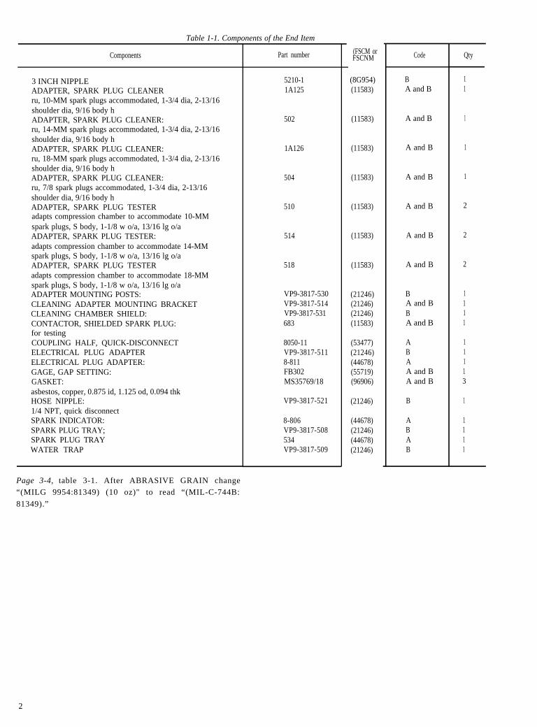
c. Parts included with the end item and consid-ered as components of the end item configurationare listed in the following table 1-1:
1
Table 1-1. Components of the End Item
Components
3 INCH NIPPLEADAPTER, SPARK PLUG CLEANERru, 10-MM spark plugs accommodated, 1-3/4 dia, 2-13/16shoulder dia, 9/16 body hADAPTER, SPARK PLUG CLEANER:ru, 14-MM spark plugs accommodated, 1-3/4 dia, 2-13/16shoulder dia, 9/16 body hADAPTER, SPARK PLUG CLEANER:ru, 18-MM spark plugs accommodated, 1-3/4 dia, 2-13/16shoulder dia, 9/16 body hADAPTER, SPARK PLUG CLEANER:ru, 7/8 spark plugs accommodated, 1-3/4 dia, 2-13/16shoulder dia, 9/16 body hADAPTER, SPARK PLUG TESTERadapts compression chamber to accommodate 10-MMspark plugs, S body, 1-1/8 w o/a, 13/16 lg o/aADAPTER, SPARK PLUG TESTER:adapts compression chamber to accommodate 14-MMspark plugs, S body, 1-1/8 w o/a, 13/16 lg o/aADAPTER, SPARK PLUG TESTERadapts compression chamber to accommodate 18-MMspark plugs, S body, 1-1/8 w o/a, 13/16 lg o/aADAPTER MOUNTING POSTS:CLEANING ADAPTER MOUNTING BRACKETCLEANING CHAMBER SHIELD:CONTACTOR, SHIELDED SPARK PLUG:for testingCOUPLING HALF, QUICK-DISCONNECTELECTRICAL PLUG ADAPTERELECTRICAL PLUG ADAPTER:GAGE, GAP SETTING:GASKET:asbestos, copper, 0.875 id, 1.125 od, 0.094 thkHOSE NIPPLE:1/4 NPT, quick disconnectSPARK INDICATOR:SPARK PLUG TRAY;SPARK PLUG TRAYWATER TRAP
Part number
5210-11A125
502
1A126
504
510
514
518
VP9-3817-530VP9-3817-514VP9-3817-531683
8050-11VP9-3817-5118-811FB302MS35769/18
VP9-3817-521
8-806VP9-3817-508534VP9-3817-509
(FSCM orFSCNM
(8G954)(11583)
(11583)
(11583)
(11583)
(11583)
(11583)
(11583)
(21246)(21246)(21246)(11583)
(53477)(21246)(44678)(55719)(96906)
(21246)
(44678)(21246)(44678)(21246)
Code
BA and B
A and B
A and B
A and B
A and B
A and B
A and B
BA and BBA and B
ABAA and BA and B
B
ABAB
Qty
11
1
1
1
2
2
2
1111
11113
1
1111
Page 3-4, table 3-1. After ABRASIVE GRAIN change
“(MILG 9954:81349) (10 oz)" to read “(MIL-C-744B:
81349).”
2
Add Appendix B after Appendix A as follows
APPENDIX BBASIC ISSUE ITEMS LIST
ANDITEMS TROOP INSTALLED OR AUTHORIZED LIST
Section I. INTRODUCTION
1. ScopeThis appendix lists basic issue items and itemstroop installed or authorized required by thecrew/operator for operation of the spark plugcleaner and tester.
2. GeneralThis Basic Issue Items List and Items Troop In-stalled or Authorized List is divided into the fol-lowing sections:
a. Basic Issue Items List. Not applicable.b. Items Troop Installed or Authorized List. Not
applicable.
3. Explanation of ColumnsThe following provides an explanation of columnsfound in the tabular listings
a. Federal Stock Number. Indicates the Federalstock number assigned to the item and will be usedfor requisitioning purposes.
b. Description. Indicates the Federal item nameand a minimum description required to identifythe item. The last line indicates the reference num-ber followed by the applicable Federal Supply Codefor Manufacturer (FSCM) in parentheses. TheFSCM is used as an element in item identificationto designate manufacturer or distributor or gov-
Page D-1. Appendix D title is changed to read asfollows:
ernment agency, etc., and is identified in SB 708-42.Items that are included in kits and sets and listedbelow the name of the kit or set with quantity ofeach item in the kit or set indicated in front of theitem name.
c. Unit of Measure (U/M). Indicates the standardor basic quantity by which the listed item is usedin performing the actual maintenance function.This measure is expressed by a two-characteralphabetical abbreviation, e.g., ea, in., pr, andis the basis used to indicate quantities. When theunit of measure differs from the unit of issue, thelowest unit of issue that will satisfy the requiredunits of measure will be requistioned.
d. Quantity Furnished with Equipment (Basiccolumns ItemsOnly). Indicates the quantity of the itemfurnished with the equipment.
e. Quanity Authorized (Items Troop Installedor Authorized Only). Indicates the quantity autho-rized to be used with the equipment.
f. Illustration (Basic Issue Items Only). This col-umn is divided as follows
(1) Figure number. Indicates the figure number
APPENDIX DORGANIZATIONAL MAINTENANCE
Paragraph D-1 is superseded as follows:
D-1. SCOPE
This appendix lists repair parts required bycrew/operator for operation and required forperformance of organizational maintenance of
thethe
illustration in which the item is shown.Item number. Indicates the item numberidentify each item called out in the illustra-
REPAIR PARTS LIST
spark plug cleaner and tester.Paragraph D-2d is rescinded.Page D-5. Section V, Tools and Support Equipmentis rescinded.Page D-6. Section VI is superseded as follows:
3
Page D-8
1-1.
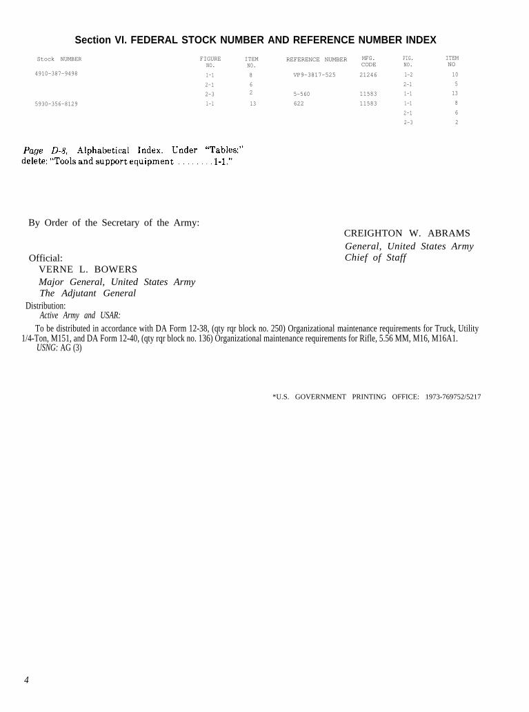
Section VI. FEDERAL STOCK NUMBER AND REFERENCE NUMBER INDEX
Stock NUMBER FIGURE ITEM REFERENCE NUMBER MFG. FIG. ITEMNO. NO. CODE NO. NO
4910-387-9498 1-1 8 VP9-3817-525 21246 1-2 10
2-1 6 2-1 5
2-3 2 5-560 11583 1-1 13
5930-356-8129 1-1 13 622 11583 1-1 8
2-1 6
2-3 2
By Order of the Secretary of the Army:CREIGHTON W. ABRAMSGeneral, United States ArmyChief of StaffOfficial:
VERNE L. BOWERSMajor General, United States ArmyThe Adjutant General
Distribution:Active Army and USAR:
To be distributed in accordance with DA Form 12-38, (qty rqr block no. 250) Organizational maintenance requirements for Truck, Utility1/4-Ton, M151, and DA Form 12-40, (qty rqr block no. 136) Organizational maintenance requirements for Rifle, 5.56 MM, M16, M16A1.
USNG: AG (3)
*U.S. GOVERNMENT PRINTING OFFICE: 1973-769752/5217
4
i
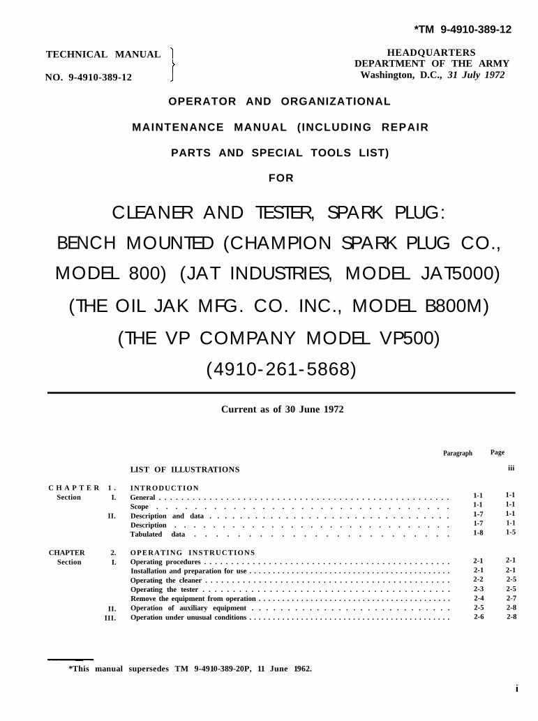
*TM 9-4910-389-12
TECHNICAL MANUAL HEADQUARTERSDEPARTMENT OF THE ARMY
NO. 9-4910-389-12 Washington, D.C., 31 July 1972
OPERATOR AND ORGANIZATIONAL
MAINTENANCE MANUAL (INCLUDING REPAIR
PARTS AND SPECIAL TOOLS LIST)
FOR
CLEANER AND TESTER, SPARK PLUG:
BENCH
MODEL
MOUNTED (CHAMPION SPARK PLUG CO.,
800) (JAT INDUSTRIES, MODEL JAT5000)
(THE OIL JAK MFG. CO. INC., MODEL B800M)
(THE VP COMPANY MODEL VP500)
(4910-261-5868)
Current as of 30 June 1972
LIST OF ILLUSTRATIONS
C H A P T E R 1 . INTRODUCTIONSection I. General . . . . . . . . . . . . . . . . . . . . . . . . . . . . . . . . . . . . . . . . . . . . . . . . . . . .
*This manual supersedes TM 9-4910-389-20P, 11 June 1962.
Paragraph Page
C H A P T E R 3 .Section I.
II.
III.IV.
C H A P T E R 4 .S e c t i o n I .
II.III.IV.V.
VI.VII.
VIII.
A P P E N I X A .
C.
D.
OPERATOR /CREW MAINTENANCE INSTRUCTIONSL u b r i c a t i o n i n s t r u c t i o n s General . . . . . . . . . . . . . . . . . . . . . . . .Cleaning . . . . . . . . . . . . . . . . . . . . . . . .Preventive maintenance checks and services ,. ,.Troubleshooting . . .Maintenance procedures . . . . . . . . . . . . . . . . . . . . . . . . . .
1-1. SCOPEa. This manual is for your use in operating and
maintaining the spark plug cleaner and tester.(Champion, model 800) (JAT, model JAT5000)(Oiljak, model B800M) (VP, model VP500).
b. Appendix A contains a list of currentreferences, including forms, technical manuals, andother available publications applicable to the sparkplug cleaner and tester.
c. Appendix B—BASIC ISSUE ITEMS LIST(BILL) AND ITEMS TROOP INSTALLED ORAUTHORIZED LIST (ITIAL)-not applicable.
d. Appendix C contains the MaintenanceAllocation Chart for the spark plug cleaner andtester, listing all maintenance and repair operationsauthorized by maintenance echelons.
e. Appendix D contains Repair Parts, and Toolsand Support Equipment for operating and per-forming organizational maintenance on the sparkplug cleaner and tester.
GENERAL
1-2. Maintenance Forms and Records.Maintenance forms and records that you arerequired to use are explained in TM 38-750.
1-3. Reporting of Errors. You can improve thismanual by calling attention to errors and byrecommending improvements, using DA Form2028 (Recommended Changes to Publications], orby a letter, and mail directly to: CommandingGeneral, Headquarters, U. S. Army WeaponsCommand, ATTN: AMSWE-MAS, Rock Island,IL 61,201 ..4 reply will be furnished directly to you.
1-4. Equipment Serviceability Criteria(ESC). This equipment is not covered by an ESC.1-5. Destruction of Army Materiel to PreventEnemy Use. Refer to DOD 4160.21-M-1 fordestruction of materiel to prevent enemy use.1-6. Administrative Storage. Refer to TM 740-90-1 for administrative storage.
Section II. DESCRIPTION AND DATA
1-7. Description. You can clean and test used components. The four models of Cleaner andaircraft and automotive type spark plugs with any Tester, Spark Plug (4910-261-58-8) aremodel listed. The maintenance paragraphs of this designated as codes “A” and “B.” Codes “A” andmanual contains detailed descriptions of their “B” vary only in appearance.
1-1
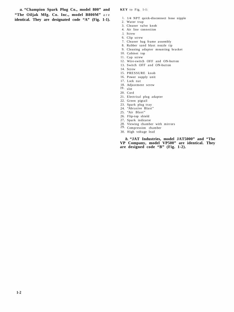
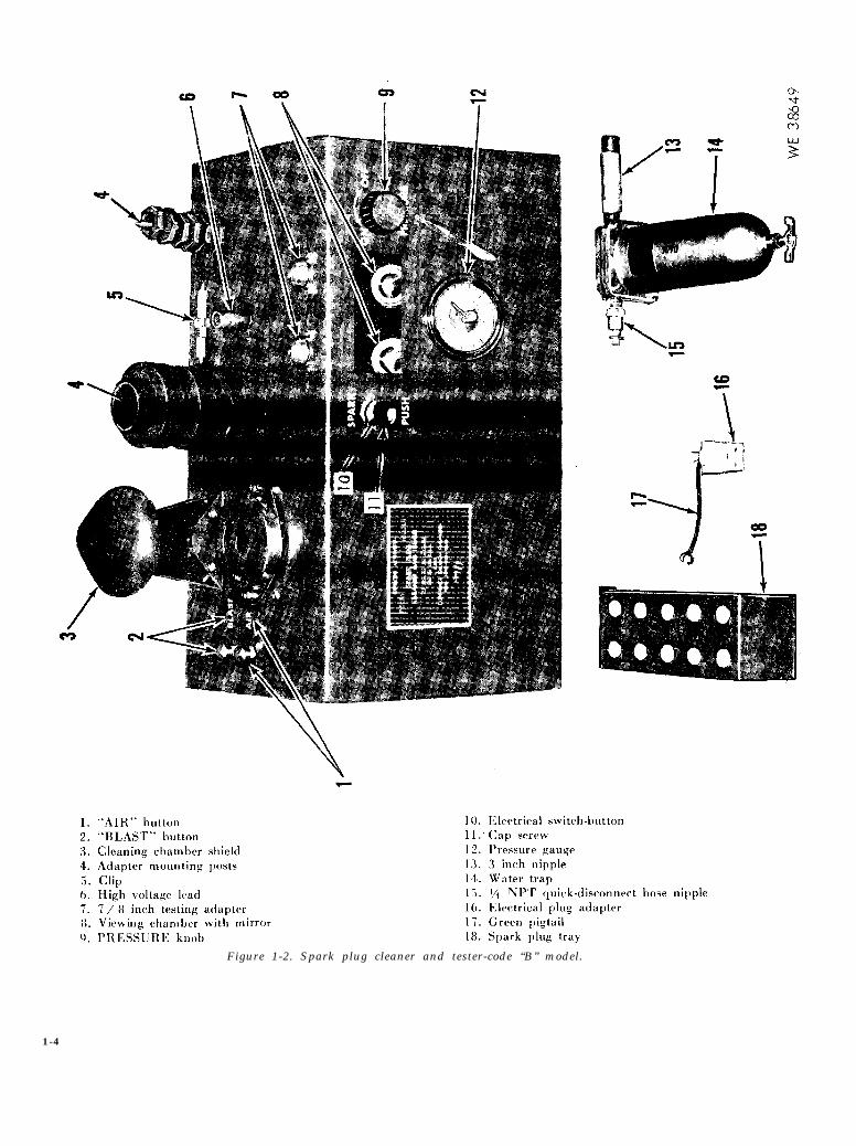
a. “Champion Spark Plug Co., model 800” and KEY to Fig. 1-1:
“The Oiljak Mfg. Co. Inc., model B800M” areidentical. They are designated code “A” (Fig. 1-1). 1.
1/4 NPT quick-disconnect hose nippleWater trapCleaner valve knobAir line connectionScrewClip screwCleaner bag frame assemblyRubber sand blast nozzle tipCleaning adapter mounting bracketCabinet topCap screwWire-switch OFF and ON-buttonSwitch OFF and ON-buttonScrewPRESSURE knobPower supply unitLock nutAdjustment screwslotCordElectrical plug adapterGreen pigtailSpark plug tray“Abrasive Blast”“Air Blast”Flip-top shieldSpark indicatorViewing chamber with mirrorsCompression chamberHigh voltage lead
b. “JAT Industries, model JAT5000” and “TheVP Company, model VP500” are identical. Theyare designed code “B” (Fig. 1-2).
1-2
Figure 1-1. Spark plug cleaner and tester-code “A” model.
1-3
Figure 1-2. Spark plug cleaner and tester-code “B” model.
1-4
c. Parts included with end item and considered 1-8. Tabulated Data. The identification plate ispart of end item are listed in Table 1-1. Check part located on the exterior of unit. It identifies thenumber in Appendix D for manufacturer’s code, nomenclature (SPARK PLUG CLEANER ANDand location by figure and item number. TESTER), manufacturer, model, FSN (4910-261-
Table 1-1. Parts Included With End Item5868) , serial and contract number, Table 1-2contains tabulated data.
Part
3 inch nippleAdapter mounting postsCleaning chamber shieldElectrical plug adapter
Hose nipple, 1/4 NPT,quick-disconnect
Spark indicatorSpark plug tray
Water trap
Part Number:
FSCM orFSCNM
5210-1:8G954VP9-3817-530:21246VP9-3817-531:21246
8-811:44678VP9-3817-511:21246VP9-3817-521:21246
8-806:44678534:44678
VP9.3817-508:21246VP9-3817-509:21246
Code
BBBABB
AABB
1 - 5
Table 1-2.
1-6
CHAPTER 2
OPERATING INSTRUCTIONS
WARNING Use extreme caution to be sure voltage is notCompressed air can produce air bubbles in the applied to high voltage lead except whenblood stream (embolism). Air can enter body required in test.through minor cuts. Embolism can be ex- If equipment fails to operate, refer totremely painful and somet imes FATAL. troubleshooting procedures in chapter 3.Disconnect air line before performing main- Do not inhale cleaning solvent for prolongedtenance or troubleshooting on compressed air periods.system other than adjustment of air pressure.You will wear goggles when cleaning plugs.This will keep abrasive grain out of eyes.
Section I. OPERATING PROCEDURES
2-1. Installation and Preparation for Use. VAC, 50-60 cycles) . If this type outlet is not
a. Secure Unit. Unit (Fig. 1-1 or 1-2) may be available, use the electrical plug adapter (21, Fig.
fastened to work bench through holes provided. 1-1 or 16, Fig. 1-2). Secure the green pigtail (22,
b. Connect Cord. Connect cord (20, Fig. 1-1 or Fig. 1-1 or 17, Fig. 1-2) to a suitable ground on the
1, Fig. 2-1) to a mating 3 wire electrical outlet (115 outlet box.
2-1
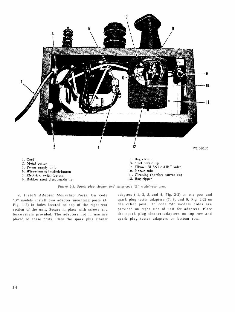
Figure 2-1. Spark plug cleaner and tester-code “B” model-rear view.
c. Install Adapter Mounting Posts. On code adapters ( 1, 2, 3, and 4, Fig. 2-2) on one post and
“B” models install two adapter mounting posts (4, spark plug tester adapters (7, 8, and 9, Fig. 2-2) onFig. 1-2) in holes located on top of the right-rear the other post. On code “A” models holes aresection of the unit. Secure in place with screws and provided on right side of unit for adapters. Placelockwashers provided. The adapters not in use are the spark plug cleaner adapters on top row and
placed on these posts. Place the spark plug cleaner spark plug tester adapters on bottom row.
2-2
2-3
figure 2-2.
fIG. 2-3
d. Install Cleaning Chamber Shield. On code“13” models install cleaning chamber shield (3, F i g .
1-2) to lef t of above posts . Secure in p lace wi thscrews, lockwashers , and nuts provided . On code“A” models a f l ip- top sh ie ld (26 , F ig . 1-1) i s a t -t a c h e d o n t o p - l e f t p o s i t i o n . T h e s h i e l d p r e v e n t sabrasive grain from getting into your eyes, however,see above W A R N I N G .
e. Install Water Trap and Air Line Hose. O ncode “B’’ models screw 3 inch nipple ( 13, Fig. 1-2)into elbow at bottom of “BLAST / AIR” valve (9,F i g . 2 - 1 ) . u s i n g p l u m b i n g p u t t y . T h i s v a l v e i slocated at the rear inside of unit on top right side.Screw water trap (14, Fig. l-2) on 3 inch nipple.Screw 1/4 NPT quick-disconnect hose nipple (15,Fig. 1-2) on water trap. On all models connectstandard air line (120 to 150 PSI) to the 1/4 NPTnipple on water trap to supply compressed air tounit. On code “A” models the 1/4 NPT quick-disconnect hose nipple (1, Fig, 1-1) is entended
from unit on left side. Water from compressed air iscollected in water trap (2, Fig. 1-1 or 14, Fig. 1-2).W h e n c o m p r e s s e d a i r i s u s e d o b s e r v e a b o v e
W A R N I N G .f . S e c u r e S h i e l d e d S p a r k P l u g C o n t a c t o r . O n
code “B” models p lace sh ie lded spark p lug con-tactor (5, Fig. 2-2) into clip (5, Fig, 1-2) located
between adapter mounting posts in c above. A clipis not provided on code “A” models . This contac tor
is used to test Army type plugs. It is inserted intoplug to adapt it for use with high voltage lead (30,Fig. 1-1 or 6, Fig. 1-2). Observe above WARNING
concerning high voltage lead.g. Cleaning Chamber.
(1) On code “A” models the c leaner bagframe assembly (7, Fig. 1-1 and Fig. 2-3) is in-stalled inside of unit below the flip-top shield in
Figure 2-3.
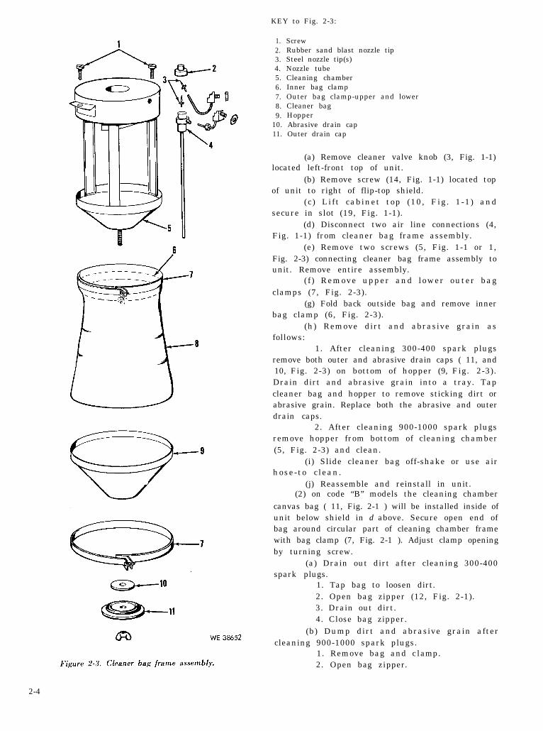
KEY to Fig. 2-3:
1.2.3.4.5.6.7.8.9.
10.11.
ScrewRubber sand blast nozzle tipSteel nozzle tip(s)Nozzle tubeCleaning chamberInner bag clampOuter bag clamp-upper and lowerCleaner bagHopperAbrasive drain capOuter drain cap
(a) Remove cleaner valve knob (3, Fig. 1-1)located left-front top of unit.
(b) Remove screw (14, Fig. 1-1) located topof unit to right of flip-top shield.
(c) Lift cabinet top (10, Fig. 1-1) andsecure in slot (19, Fig. 1-1).
(d) Disconnect two air line connections (4,Fig. 1-1) from cleaner bag frame assembly.
(e) Remove two screws (5, Fig. 1-1 or 1,Fig. 2-3) connecting cleaner bag frame assembly tounit. Remove entire assembly.
( f ) Remove upper and lower outer bagclamps (7, Fig. 2-3).
(g) Fold back outside bag and remove innerbag clamp (6, Fig. 2-3).
(h) Remove dirt and abrasive grain asfollows:
1. After cleaning 300-400 spark plugsremove both outer and abrasive drain caps ( 11, and10, Fig. 2-3) on bottom of hopper (9, Fig. 2-3).Drain dirt and abrasive grain into a tray. Tapcleaner bag and hopper to remove sticking dirt orabrasive grain. Replace both the abrasive and outerdrain caps.
2. After cleaning 900-1000 spark plugsremove hopper from bottom of cleaning chamber(5, Fig. 2-3) and clean.
(i) Slide cleaner bag off-shake or use airhose-to c lean.
(j) Reassemble and reinstall in unit.(2) on code “B” models the cleaning chamber
canvas bag ( 11, Fig. 2-1 ) will be installed inside ofunit below shield in d above. Secure open end ofbag around circular part of cleaning chamber framewith bag clamp (7, Fig. 2-1 ). Adjust clamp openingby turning screw.
(a) Drain out dirt after cleaning 300-400spark plugs.
1. Tap bag to loosen dirt.2. Open bag zipper (12, Fig. 2-1).3. Drain out dirt.4. Close bag zipper.
(b) Dump dirt and abrasive grain aftercleaning 900-1000 spark plugs.
1. Remove bag and c l a m p .2 . Open bag z ipper .
2-4
3. Dump dirt and abrasive grain.4. Shake—or use air hose—to clean bag.5. Reinstall bag inside of unit.
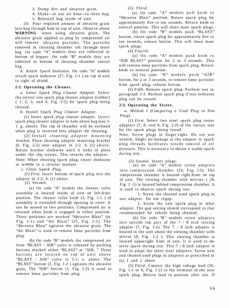
(3) Pour required amount of abrasive graininto bag through hole in top of unit. Observe aboveWARNING when using abrasive grain. Theabrasive grain applied to plug by compressed airwill remove abrasive particles. The particlesremoved in cleaning chamber sift through innerbag. On code “A” models they are collected inbottom of hopper. On code “B” models they arecollected in bottom of cleaning chamber canvashag.
h. Attach Spark Indicator. On code “A” modelsattach spark indicator (27, Fig. 1-1 ) on top of unitto right of shield.
2-2. Operating the Cleaner.a. Select Spark Plug Cleaner Adapter. Select
the correct size spark plug cleaner adapter (rubber)( 1, 2, 3, and 4, Fig. 2-2) for spark plug beingcleaned.
spark plug cleaner adapter in hole above bag (see 2-l. g. above). The top of chamber will be enclosedwhen plug is inserted into adapter for cleaning.
(2) Install cleaning adapter mountingbracket. Place cleaning adapter mounting bracket(6, Fig. 2-2) over adapter in 2-2. b. (1) above.Rotate bracket clockwise until it locks in placeunder the clip screws. This secures the adapter.Note: When cleaning spark plug, rotate clockwiseor wobble in a circular manner.
c. Clean Spark Plug.(1) First. Insert bottom of spark plug into the
adapter in 2-2. b. (1) above.(2) Second.
(a) On code “A” models the cleaner valveassembly is located inside of unit on left-frontposition. The cleaner valve knob (3, Fig. 1-1 ) ofassembly is extended through opening in cover. Itcan be moved to two positions. Compressed air is
released when knob is engaged in either position.These positions are marked “Abrasive Blast” (24,
Fig. 1-1) and “Air Blast” (25, Fig. 1-1). The“Abrasive Blast” agitates the abrasive grain. The“Air Blast” is used to remove loose particles fromplug.
(b) On code “B” models the compressed airfrom “BLAST / AIR” valve is released by pushingbuttons marked either “BLAST” or “AIR. ” Thesebuttons are located on top of unit above“BLAST / AIR” valve in 2-1. e. above. The“BLAST” button (2, Fig. 1-2 ) agitates the abrasivegrain, The “AIR” button (1, Fig. 1-2) is used toremove loose particles from plug.
(3) Third.(a) On code “A” models pull knob to
“Abrasive Blast” position. Rotate spark plug forapproximately five to ten seconds. Return knob toneutral position. This will clean most spark plugs.
(b) On code “B” models push “BLAST”button, rotate spark plug for approximately five toten seconds, release button. This will clean mostspark plugs.
(4) Fourth.(a) On code “A” models push knob to
“AIR BLAST” position for 2 or 3 seconds. Thiswill remove loose particles from spark plug. Returnknob to neutral position.
(b) On code “B” models push “AIR”button, for 2 or 3 seconds, to remove loose particlesfrom spark plug, release button.
(5) Fifth. Remove spark plug. Perform test inparagraph 2-3. Reclean spark plug if test indicatesplug can be reused.
2-3. Operating the Tester.a. Method I (Comparing a Used Plug to New
Plug).(1) First. Select two steel spark plug tester
adapters (7, 8, and 9, Fig. 2-2) of the correct sizefor the spark plugs being tested.Note: Screw plugs in finger-tight. Do not usewrench. Slight air-leakage at the adapter or sparkplug threads facilitates steady control of airpressure. This is necessary to obtain a stable sparkduring test.
(2) Second. Insert plugs.(a) on code “A” models screw adapters
into compression chamber (29, Fig. l-I). Thecompression chamber is located right-front on topof unit. The viewing chamber with mirrors ( 28,Fig. 1 -1) is located behind compression chamber. Itis used to observe spark during test.
1. Screw the cleaned used spark plug inone adapter. Do not regap.
2. Screw the new spark plug in otheradapter. The gap setting should correspond to thatrecommended for vehicle being checked.
(b) On code “B” models screw adaptersinto outside top part of the 7 / 8 inch testingadapter (7, Fig. 1-2). The 7 / 8 inch adapter islocated in the unit above the viewing chamber withmirror (8, Fig. 1-2 ). This viewing chamber islocated upperright front of unit. It is used to ob-serve spark during test. This 7 / 8 inch adapter isused to adapt the other steel adapters. Screw newand cleaned used plugs in adapters as prescribed in(a) 1 and 2 above.
(3) Third. Connect the high voltage lead (30,Fig. 1-1 or 6, Fig. 1-2) to the terminal of the newspark plug. Return lead to position after use. If
2-5
shielded plugs are being tested, use shielded sparkplug contactor as prescribed in paragraph 2-1. f. The high voltage lead with alligator clip, in-sulator and grommet is located between posts in 2-1. c. on code “B” models. On code “A” models it islocated in front of compression chamber. It fur-nishes the voltage for spark. Observe aboveWARNING concerning high voltage lead.
(4) Fourth. Press switch OFF and ON button(13, Fig. 1-1 ) for code “A” models or electricalswitch button (10, Fig. 1-2) for code “B” models,located left of viewing chamber. Watch spark inviewing chamber. Increase air pressure by turningPRESSURE knob (15, Fig. 1-1 or 9, Fig, 1-2)located to right of viewing chamber. The spark willquench out when pressure passes the sparkingefficiency of the new plug. Reduce pressure untilthe spark becomes steady.
(5) Fifth. Mark reading of new plug.(a) On code “A” models the spark indicator
(27, Fig. 1-1 or Fig. 2-4) is located above andbehind viewing chamber. Keep switch buttonpressed and move dial of indicator till the rightedge of the “Green” or “Good” area (Fig. 2-4) isaligned with the gauge pointer (Fig. 2-4) (disregardgap setting arrow (Fig. 2-4)). The reading on in-dicator is the amount of pressure reached for newplug. This is the sparking efficiency of the newplug. Release switch button. The cleaned usedspark plug will be compared to this reading. Thescale on indicator is numbered every 20 psi.Numbering starts at 40 psi with markings every 4psi to maximum of 200 psi.
Figure 2-4. Dials.
(b) On code “B” models the pressure gauge(12, Fig. 1-2 or Fig. 2-4) is located below viewingchamber. Keep switch button pressed and rotatedial on gauge until the “Green” or “Good” area(Fig. 2-4) lines up guage gauge needle (Fig. 2-4).(Only one needle on gauge, two needles are shownon illustration to show sample of readings for newand used plugs). This is the sparking efficiency ofthe new plug. Release switch button. The cleanedused spark plug will be compared to this reading.The scale on pressure gauge is numbered every 20psi. The range is 0 psi to 200 psi wiith markingsevery 5 psi.
(6) Sixth. Remove the high voltage lead fromthe new spark plug and clip on the cleaned usedplug.
(7) Seventh. Obtain a steady spark on usedplug as prescribed in (4) above. Compare readingof cleaned used spark plug with reading of new plugin (5) (a) and (5) (b) above. The reading will be inone of the following areas:
(a) The green or good area (higher readingthan this means used plug is better than new plug)indicates cleaned used spark plug is in good con-dition and will be reused.
(b) The yellow or fair area (Fig. 2-4) in-dicates cleaned used spark plug requires ap-proximately 50 per cent of the available ignitionsystem voltage. This area is located to left of area in(a) above. Replacement of plug is recommended. Ifconditions make this undesirable, the plug may bereused. The plug can generally be cleaned andserviced. The spark plug electrodes cannot be tooseverely eroded or deteriorated.
(c) The red or replace area (Fig. 2-4)indicates cleaned used spark plug requires 75 percent or more of the available ignition systemvoltage. This area is located to left of area in (b)above. The plug is in bad condition and will bereplaced.
b. Method II (Testing Two Used Plugs). O n i ycode “A” models are equipped to perform thismethod.
(1) First. Select two steel spark plug testeradapters (7, 8, and 9, Fig. 2-2) of the correct sizefor the spark plugs being tested.Note: Screw plugs in finger-tight. Do not usewrench.S l i ght a i r - l eakage a t the adapter o r sparkplug threads facilitates steady control of airpressure. This is necessary to obtain a stable sparkduring test,
(2) Second. Screw adapters into compressionchamber (29, Fig. 1-1). The compression chamberis located right-front on top of unit. The viewing
2-6
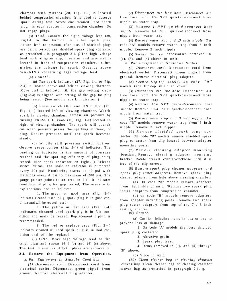
chamber with mirrors (28, Fig. 1-1) is locatedbehind compression chamber, It is used to observespark during test. Screw one cleaned used sparkplug in each adapter in compression chamber. Donot regap plugs.
(3) Third. Connect the hig~h voltage lead (30,Fig.1-1 to the terminal of either spark plug.Return lead to position after use. If shielded plugsare being tested, use shielded spark plug contactoras prescirbed , in paragraph 2-1. f. The high voltagelead with alligator clip, insulator and grommet islocated in front of compression chamber. It fur-nishes the voltage for spark. Observe aboveWARNING concerning high voltage lead.
(4) F o u r t h .{al The spark indicator (27, Fig. 1-1 or Fig.
2-4) is Iocated above and behind viewing chamber.Move dial of indicator till the gap setting arrow(Fig .2-4) is aligned with setting of the gap for plugbeing tested. (See middle spark indicator. )
(b) Press switch OFF and ON button (13,Fig. 1-1) located left of viewing chamber. Watchspark in viewing chamber. Increase air pressure byturning PRESSURE knob (15, Fig. 1-1) located toright of viewing chamber. The spark will quenchout when pressure passes the sparking efficiency ofplug. Reduce pressure until the spark becomessteady.
(c) W bile still pressing switch button,observe gauge pointer (Fig. 2-4) of indicator. Thereading on indicator is the amount of pressurereached and the sparking efficiency of plug beingtested. (See spark indicator on right. ) Releaseswitch button. The scale on indicator is numberedevery 20) psi. Numbering starts at 40 psi withmarkings every 4 psi to maximum of 200 psi. Thegauge pointer points to an area on dial. It indicatescondition of plug for gap tested, The areas withexplanations are as follows:
1. The green or good area (Fig. 2-4)indicates cleaned used plug spark plug is in good con-dition and will be reused used.
2. The yellow or fair area ( F i g . 2 - 4 )indicuates clreaned used spark plg is in fair con-dition and maiy be reused. Replacement f plug isrecommended.
3. The red or replace area (Fig. 2-4)indicates cleaned ui used spark plug is in bad con-dition and will be replaced.
(5) Fifth. Move high voltage lead to theother plug and repeat (4 I (b) and (4) (c) above.The test determines if both plugs are serviceable.
2-4. Remove the Equipment from Operation.
a. Put Equipment in Standby Condition.(1) Disconnect cord. Disconnect cord from
electrical outlet. Disconnect green pigtail fromground. Remove electrical plug adapter.
(2) Disconnect air line hose. Disconnect airline hose from 1/4 NPT quick-disconnect hosenipple on water trap.
(3) Remove 1 NPT qu i ck -d i s connec t hosenipple. Remove l/4 NPT quick-disconnect hosenipple from water trap.
(4) Remove water trap and ,3 inch nipple. O ncode “B” models remove water trap from 3 inchnipple. Remove 3 inch nipple.
(5) Secure. Secure accessories removed in(1), (3), and (4) above in unit.
b. Put Equipment in Shutdown Status.(1) Disconnect cord. Disconnect cord
electrical outlet. Disconnect green pigtailground. Remove electrical plug adapter.
(2) Secure f l ip-top shield. O n c o d emodels tape flip-top shield to cover.
fromfrom
“ A ”
(3) Disconnect air line hose. Disconnect airline hose from 1/4 NPT quick-disconnect hosenipple on water trap.
(4) Remove 1/4 NPT quick-disconnect hosenipple. Remove 11/4 NPT quick-disconnect hosenipple from water trap.
(5) Remove water trap and 3 inch nipple. O ncode “B” models remove water trap from 3 inchnipple. Remove 3 inch nipple.
(6 ) R e m o v e s h i e l d e d s p a r k p l u g c o n -tactor. On code “B” models remove shielded sparkplug contactor from clip located between adaptermounting posts.
(7) R e m o v e c l e a n i n g a d a p t e r m o u n t i n gbracket . Remove c leaning adapter mountingbracket. Rotate bracket counter-clockwise until it isfree of the clip screws.
(a) On code “A” models remove adaptersfrom right side of unit. “Remove two spark plugtester adapters from compression chamber.
(b) on code “B” models remove adaptersfrom adapter mounting posts. Remove two sparkplug tester adapters from top of the 7 / 8 inchtesting adapter.
(9) Secure.
(a) Cushion following items in box or bag toprevent loss or damage:
1. On code “A” models the loose shieldedspark plug contactor.
2. Abrasive grain.3. Spark plug tray.4. Items removed in
(8) above.(b) Store in unit.
(1), and (4) through
(10) Clean cleaner bag or cleaning chambercanvas bag. Clean cleaner bag or cleaning chamber
canvas bag as prescribed in paragraph 2-1. g.
2-7
Section II. OPERATION OF AUXILIARY EQUIPMENT
2-5. Auxiliary Equipment. N o auxiliaryequipment is required on the spark plug cleanerand tester.
Section III. OPERATION UNDER UNUSUAL CONDITIONS
2-6 . Unusual Condit ions . The spark p lug be met would eliminate unusual operating con-cleaner and tester has electrical and compressed air ditions. No addit ional operating instructionsrequirements. Area where these requirements can required.
2-8
3-1
CHAPTER 3
O P E R A T O R / C R E W M A I N T E N A N C E I N S T R U C T I O N S
Section I. LUBRICATION INSTRUCTIONS
3-1. Lubricatoin. No lubrication is required onthe Spark Plug cleaner and tester.
.Section II. PREVENTIVE MAINTENANCE CHECKS AND SERVICES (PMCS)
3-2. General. To insure that the Spark PlugCleaner and ‘I’ester is ready for operation at alltimes, is must be inspected systematically so thatdefects may be discovered and corrected beforethey result in serious damage or failure. Thenecessary preventive maintenance checks andservices to be performed are listed as described inparagraph 3-4. The item numbers indicate thesequence of minimum inspection requirements.The work measurement time in tenths of hour isincluded in Table 3-1 below item number. Defectsdiscovered during operation of the unit will benoted for future correction to be made as soon asoperation has ceased. Stop operation immediately ifa deficiency is noted during operation which woulddamage the equipment if operation were continued.All deficieneies and shortcomings will be recordedtogether with the corrective action taken on DAForm 2404 at the earliest possible opportunity.
a. Responsibility and Intervals. The primaryfunction of preventive maintenance is to preventbreakdowns and, therefore, the need for repair.These services consist generally of before-operationand after-operation services performed by theoperator, Intervals are based on normal operations.Reduce intervals for abnormal operations for severeconditions. Intervals during the inactive periodsmay be extended accordingly.
b. Definition of Terms. The general inspectionof each item applies also to any supporting memberor connection and is generally a check to seewhether the item is in good condition, correctlyassembled. secure, and not excessively worn.
(1) The inspection for “good condition” isusually an external visual inspection to determinewhether the unit is dam aged beyond serviceablelimits. The term “good condition” is explainedfurther by the following: not bent or twisted, notchaffed or burred, not broken or cracked, not bareor frayed, not dented or collapsed, not torn or cut,not deteriorated.
(2) The inspection of a unit to see that it is“correctly assembled” is usually an external visual
inspection to see whether it is in normal assembledposition.
(3) Inspection of a unit to determine if it is“secure “ is usually an external visual examinationb y h a n d o r wrench for looseness. Such anexamination must include any brackets, lock-washers, locknuts, locking wires, or cotter pinsused.
(4) By “excessively worn” is meant wornbeyond serviceable limits or to a point likely toresult in failure if the unit is not replaced before thenext scheduled inspection.
3-3. Cleaning.
a. General. Any special cleaning instructionsrequired for specified components or parts arecontained in the pertinent section. General cleaninginstructions are as outlined in (1) through (4)below:
(1) Metal parts.(a) Use self-emulsifying decreasing solvent
compound, mineral spirits paint thinner, or dry-cleaning solvent to clean or wash grease or oil fromall metal parts of the spark plug cleaner and tester.
(b) Use clean water or a solution of either1/4 pound of soap chips or 6 ounces of painted-surface detergent to one gallon of hot water for allparts and overall general cleaning of paintedsurfaces.
(c) After parts are clean, dry themthoroughly. Apply a light film of special preser-vative lubricating oil to all parts having a polishedsurface to prevent misting.
(d) Before installing new parts, remove anyrust-preventing compound, protective grease, etc.
(2) E l e c t r i c a l par t . Use technicaltrichloroethane (methylchloroform) (O-T-620) forcleaning electrical parts. Clean painted parts andplastics by wiping, brushing, or spraying but neverby immersing in tr ichloroethane. Do not usetrichloroethane for cleaning leather or rubber parts(other than neoprene).
(3) Rubber parts other than electrical. C l e a nrubber parts with soap and warm water. Apply
coating of powdered technical talcum to preservethe rubber,
(4) Meters. Clean each meter window glassusing a soft cloth dampened with a solution ofcommon detergent and water. After cleaning, allowthe meter window to dry without rubbing. Applyantistatic compound.
b. General Precautions in Cleaning.(1) Trichloroethane. Provide adequate
ventilation both during and after use oftrichloroethane. Avoid prolonged inhalation ofvapor. Rubber gloves should be worn since thiscleaner has a drying effect on the skin.
(2) Other cleaning agents. Self -emulsi fyingdecreasing solvent compound, mineral spirits paintthinner, and dry-cleaning solvent are flammableand should not be used near an open flame. Fireextinguishers should be provided when thesematerials are used. Use only in well ventilatedplaces. These cleaners evaporate quickly and havea drying effect on the skin. If used without gloves,they may cause cracks in the skin, and, in the caseof some individuals , a mildflammation.
(3) Rubber parts. A v o i dproducts, such as mineral spiritscleaning solvent, engine fuels,
irritation or in-
getting petroleumpaint thinner, dry-er lubricants, on
rubber parts, as they will deteriorate the rubber.(4) Prohibited cleaning agents. The use of
Diesel fuel oil, gasoline, or benzene (benzol) forcleaning is prohibited.
c. Rust Removal. Remove rust or corrosion fromall parts of the material . To remove rust orc r ros i on f rom unfinished surfaces, use steelcleaning brushes or abrasive cloth. On finishedsurfaces, other than highly polished surfaces,remove rust or corrosion by buffing with a rotarywheel wire brush constructed of steel wire between0.010 and 0.025 inch in diameter. Crocus clothmay be used manually to remove rust or corrosionfrom polished surfaces.
3-4. Preventive Maintenance Checks andServices.
a. Purpose. To insure efficient operation, it isnecessary that the spark plug cleaner and tester besystematically inspected. It should be inspected atintervals each day it is operated. Inspection willdiscover defects. They will be corrected to preventserious damage or failure. Certain scheduledmaintenance services will be performed at thesedesignated intervals. The correction of any defector unsatisfactory operating characteristics beyondthe scope of the operator must be reported at theearliest opportunity to organization maintenancepersonnel for correction.
b. Services. operator’s preventive maintenancechecks and services are listed in table 3-1. Everyoperator equipped with the spark plug cleaner andtester must be thoroughly familiar with mian -tenauce procedures for the materiel.
3-2
3-1
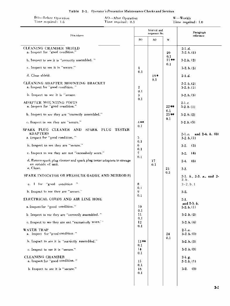
Table 3-1. Operator’s Preventive Maintenance Checks and Services
W—WeeklyTime required: 1.0
CLEANING CHAMBER SHIELDa. Inspect for “good condition.”
b. Inspect to see it is “correctly assembled. ”
c. Inspect to see it is “secure.”
d. Close shield.
CLEANING ADAPTER MOUNTING BRACKETa. Inspect for “good condition. ”
b. Inspect to see it is “secure.”
ADAPTER MOUNTING POSTSa. Inspect for “good condition.”
b. Inspect to see they are “correctly assembled.”
c. Inspect to see they are “secure.”
SPARK PLUG CLEANER AND SPARK PLUG TESTERADAPTERS
a. Inspect for “good condition. ”
b. Inspect to see they are “secure.”’
c. inspect to see they are not “excessively worn.’”
d. Return spark plug cleaner and spark plug tester adapters to storageon outside of unit.
e. Clean.
SPARK INDICATOR OR PRESSURE GAUGE AND MIRROR(S)
a. Inspect for “good condition ”
b. Inspect to see they are “secure.”
ELECTRICAL CORDS AND AIR LINE HOSE
a. Inspect for “good condition. ”
b. Inspect to see they are “correctly assembled. ”
e. Inspect to see they are not “excessively worn. ”
WATER TRAPa. Inspect for “good condition. ”
b. Inspect to see it is “correctly
c. Inspect to see it is “secure.”
CLEANING CHAMBERa. Inspect for “good condition. ”
b. Inspect to see it is “secure.”’
assembled, ”
sequence No.
Bo
10.1
20.130.1
4 **0.1
50.160.170.1
80.190.1
100.1110.1120.1
13**0.1140.1
150.1160.1
AO
19*0.1
170.1
w
200.121**0.1
22**0.123**0.1
250.5
240.1
Paragraphreference
2-1. d.3-2. b. (1)
3-2:b. (2)
3-2. b. (3)
2-l. d.
2-2. b. (2)3-2. b. (1)
3-2. b. (3)
2-1. C.3-2. b. (1)
3-2. b. (2)
3-2. b. (3)
2-1. C. and 2-4. b. (8)3-2. b. (1)
3-2.b. (3)
3-2.b. (4)
2.4.b. (8)
3-3.
2-1. h., 2-3. a., and 2-3 . b .
3 - 2 . b . 1
3-2.b(3)
2-1.b.,2-1.e.,2-3.aand 2-3. b.
3-2. b. (1)
3-2. b. (2)
3-2. b. (4)
3-2. b. (1)
3-2. b. (2)
3-2. b. (3)
2-1. g.3-2. b. (1)
3-2.b. (3)
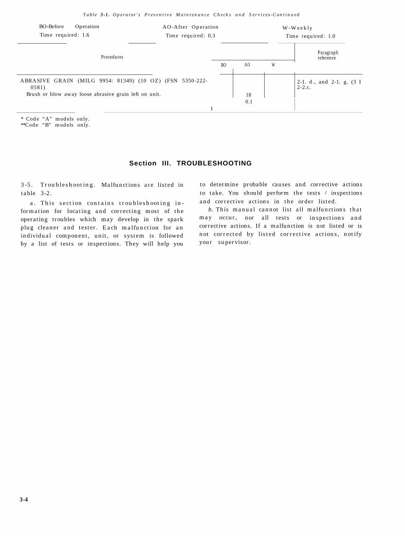
Table 3-1. Operator's Preventive Maintenance Checks and Services-Continued
BO-Before Operation AO-After Operation W-WeeklyTime required: 1.6 Time required: 0.3 Time required: 1.0
Brush or blow away loose abrasive grain left on unit. 18
I0.1 I
* Code “A” models only.**Code “B” models only.
Section III. TROUBLESHOOTING
3-5. Troubleshooting. Malfunctions are listed intable 3-2.
a. This section contains troubleshooting in-formation for locating and correcting most of theoperating troubles which may develop in the sparkplug cleaner and tester. Each malfunction for anindividual component, unit, or system is followedby a list of tests or inspections. They will help you
to determine probable causes and corrective actionsto take. You should perform the tests / inspectionsand corrective actions in the order listed.
b. This manual cannot list all malfunctions thatmay occur, nor all tests or inspections andcorrective actions. If a malfunction is not listed or isnot corrected by listed corrective actions, notifyyour supervisor.
3-4
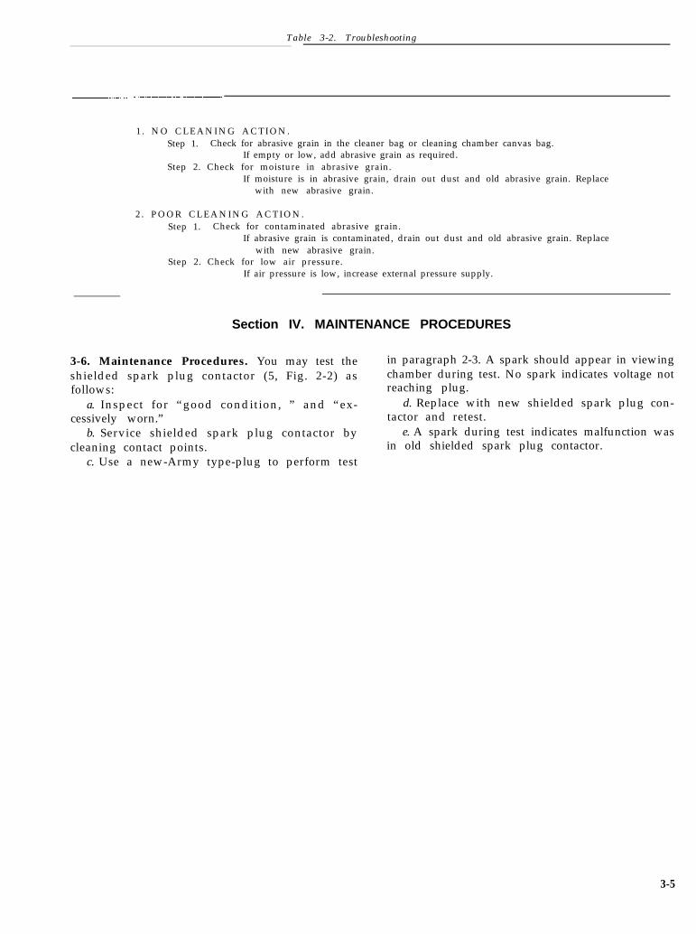
Table 3-2. Troubleshooting
1 . NO CLEANING ACTION.Step 1. Check for abrasive grain in the cleaner bag or cleaning chamber canvas bag.
If empty or low, add abrasive grain as required.Step 2. Check for moisture in abrasive grain.
If moisture is in abrasive grain, drain out dust and old abrasive grain. Replacewith new abrasive grain.
If abrasive grain is contaminated, drain out dust and old abrasive grain. Replacewith new abrasive grain.
Step 2. Check for low air pressure.If air pressure is low, increase external pressure supply.
Section IV. MAINTENANCE PROCEDURES
3-6. Maintenance Procedures. You may test theshielded spark plug contactor (5, Fig. 2-2) asfollows:
a. Inspect for “good condition, ” and “ex-cessively worn.”
b. Service shielded spark plug contactor bycleaning contact points.
c. Use a new-Army type-plug to perform test
in paragraph 2-3. A spark should appear in viewingchamber during test. No spark indicates voltage notreaching plug.
d. Replace with new shielded spark plug con-tactor and retest.
e. A spark during test indicates malfunction wasin old shielded spark plug contactor.
3-5
CHAPTER 4
ORGANIZATIONAL MAINTENANCE INSTRUCTIONS
Section I. SERVICE UPON
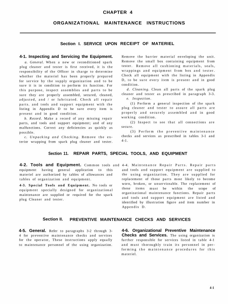
4-1. Inspecting and Servicing the Equipment.a. General. When a new or reconditioned spark
plug cleaner and tester is first received, it is theresponsibility of the Officer in charge to determinewhether the materiel has been properly preparedfor service by the supply organization and to besure it is in condition to perform its function. Forthis purpose, inspect assemblies and parts to besure they are properly assembled, secured, cleaned,adjusted, and / or lubricated. Check all repairparts. and tools and support equipment with thelisting in Appendix D to be sure every item ispresent and in good condition.
b. Record. Make a record of any missing repairparts, and tools and support equipment; and of anymalfunctions. Correct any deficiencies as quickly aspossible.
c. Unpacking and Checking. Remove the ex-terior wrapping from spark plug cleaner and tester.
RECEIPT OF MATERIEL
Section 11. REPAIR PARTS, SPECIAL
4-2. Tools and Equipment. Common tools and 4-4.equipment having general application to this andmateriel are authorized by tables of allowances and the
Remove the barrier material enveloping the unit.Remove the small box containing equipment fromtester. Remove all cushioning materials, seals,wrappings and equipment from box and tester.Check all equipment with the listing in AppendixD, to be sure every item is present and in goodcondition.
d. Cleaning. Clean all parts of the spark plugcleaner and tester as prescribed in paragraph 3-3.
e. Inspection.(1) Perform a general inspection of the spark
plug cleaner and tester to assure all parts areproperly and securely assembled and in goodworking condition.
(2) Inspect to see that all connections aresecure.
(3) Perform the preventive maintenancechecks and services as prescribed in tables 3-1 and4-1.
TOOLS, AND EQUIPMENT
Maintenance Repair Parts . Repair partstools and support equipment are supplied tousing organization. They are supplied for
tables of organization and equipment. replacement of those parts most likely to become
4-3. Special Tools and Equipment. No tools or worn, broken, or unserviceable. The replacement oftheseequipment specially designed for organizational items must be within the scope of
maintenance are supplied or required for the spark organizational maintenance functions. Repair parts
plug Cleaner and tester. and tools and support equipment are listed andidentified by illustration figure and item number inAppendix D.
Section II. PREVENTIVE MAINTENANCE CHECKS AND SERVICES
4-5. General. Refer to paragraphs 3-2 through 3- 4-6. Organizational Preventive Maintenance4 for preventive maintenance checks and services Checks and Services. The using organization isfor the operator, These instructions apply equally further responsible for services listed in table 4-1to maintenance personnel of the using organization. and must thoroughly train its personnel in per-
forming the maintenance procedures for thismateriel.
4-1
Table 4-1 . Organizational Preventive Maintenance Checks and Sercices
4-7. Troubleshooting. Malfunctions are listed in chapter three, paragraph 3-5 for troubleshootingt a b l e s 3 - 2 a n d 4 - 2 . In effect , table 4-2 is the procedures performed by the operator.continuation of table 3-2, paragraph 3-5. Refer to
4-2
4-3
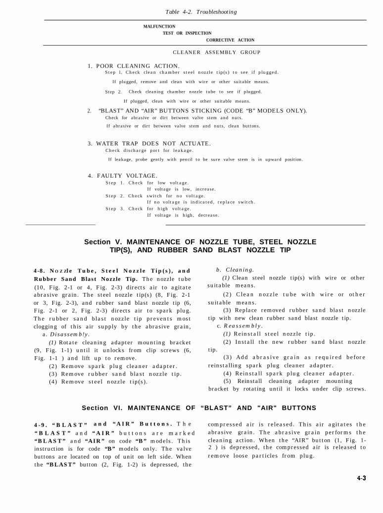
Table 4-2. Troubleshooting
MALFUNCTION
TEST OR INSPECTION
CORRECTIVE ACTION
CLEANER ASSEMBLY GROUP
1. POOR CLEANING ACTION.Step l. Check clean chamber steel nozzle tip(s) to see if plugged.
If plugged, remove and clean with wire or other suitable means.
Step 2. Check cleaning chamber nozzle tube to see if plugged.
If plugged, clean with wire or other suitable means.
2. “BLAST” AND “AIR” BUTTONS STICKING (CODE “B” MODELS ONLY).Check for abrasive or dirt between valve stem and nuts.
If abrasive or dirt between valve stem and nuts, clean buttons.
3. WATER TRAP DOES NOT ACTUATE.Check discharge port for leakage.
If leakage, probe gently with pencil to be sure valve stem is in upward position.
4. FAULTY VOLTAGE.Step 1. Check for low voltage.
If voltage is low, increase.Step 2. Check switch for no voItage.
If no voltage is indicated, replace switch.Step 3. Check for high voltage.
If voltage is high, decrease.
Section V. MAINTENANCE OF NOZZLE TUBE, STEEL NOZZLETIP(S), AND RUBBER SAND BLAST NOZZLE TIP
4-8. NO Z Zle Tube, Steel Nozzle Tip(s), andRubber Sand Blast Nozzle Tip. The nozzle tube(10, Fig. 2-1 or 4, Fig. 2-3) directs air to agitateabrasive grain. The steel nozzle tip(s) (8, Fig. 2-1or 3, Fig. 2-3), and rubber sand blast nozzle tip (6,Fig. 2-1 or 2, Fig. 2-3) directs air to spark plug.The rubber sand blast nozzle tip prevents mostclogging of this air supply by the abrasive grain,
a. Disassemb!y.(1) Rotate cleaning adapter mounting bracket
(9, Fig. 1-1) until it unlocks from clip screws (6,Fig. 1-1 ) and lift up to remove.
bracket by rotating until it locks under clip screws.
Section VI. MAINTENANCE OF “BLAST” AND "AIR" BUTTONS
4 - 9 . “ B L A S T ” a n d “ A I R ” B u t t o n s . T h e compressed air is released. This air agitates the“ B L A S T ” a n d “ A I R ” b u t t o n s a r e m a r k e d abrasive grain. The abrasive grain performs the“BLAST” and “AIR” on code “B” models. This cleaning action. When the “AIR” button (1, Fig. 1-instruction is for code “B” models only. The valve 2 ) is depressed, the compressed air is released to
buttons are located on top of unit on left side. When remove loose particles from plug.the “BLAST” button (2, Fig. 1-2) is depressed, the
4-4
a. Disassemby. c. Reassembly.
(1) Loosen nut below button on top of unit. (1) Reinstall nut to button stem.(2) Unscrew button Stem from unit. (2) Reinstall rubber valve seat to button stem.(3) Remove rubber valve seat from button (3) Screw button stem to unit.
stem . (4) Tighten nut below button, on top of unit.(4) Remove nut from button stem. (5) Repeat (i) through (4) above on other(3) Repeat (1) through (4) above on other button.
button).b. C l e a n i n g . (Clean d isassembled par ts as
prescribed in paragraph 3-3.
Section VII. MAINTENANCE OF WATER TRAP
4-10. Water Trap. The water trap (2, Fig. 1-1 or the water trap extends from rear of unit. The water14, Fig. 1-2) collects water from compressed air. trap may malfunction if valve stem is in the wrongThe water is removed before air is used in cleaning position. Inspect discharge port at bottom of waterand testing. On code “A” models the water trap is trap. A leakage indicates valve stem is in wronglocated inside of unit. It is located in the front left position. Probe valve stem gently with a pencil to
side in front of cleaner bag frame assembly and adjust in upward position.
below cleaner valve assembly. On code “B” models
Section VIII. MAINTENANCE OF SWITCHES
4-11. Switches. The switch turns the electricalpower “ON” and “OFF. ” This electrical power isused in testing the spark plug. When it is appliedto the plug, the electrical spark is used to determinethe amount of voltage required by spark plug. Thistest for sparking efficiency of spark plug determinesthe replacement of plug. When the push button ofswitch is depressed, the current is turned “ON. ”When released the button returns to “OFF”position.
a. Switch for Code “A “Models. SWITCH OFFAND ON (13, Fig. 1-1) is the name of code “A”models’ switch. It is located front-center on cover.The push button part of switch extends throughcover from the inside. It is secured in place with acap screw (11, Fig. 1-1).
b . Swi t ch f o r Code “B” Mode l s . E L E C -TRICAL SWITCH (l0, Fig. 1-2 and 5, Fig. 2-1) isthe name of code “B” models’ switch. It is locatedtop-center to left of viewing chamber on front ofunit. The push button part of switch extendsthrough unit from the inside. It is secured in placewith a cap screw ( 11, Fig. 1-2).
4-12. Testing. Test voltage by performing test onnew spark plug gapped at 0.025”. Perform the testas prescribed in paragraphs 2-3. a. (1) through 2-3.a. (4). In paragraph 2-3. a, (4) the spark of thenew plug will quench out at 140 PSI. This will bethe standard used to determine adjustment.
4-13. Adjustment.
a. Remove. On code “B” models’ remove metalbutton (2, Fig. 2- 1) on power supply unit (3, Fig. 2-1).
b. Loosen. Loosen lock nut (17, Fig. l-l) onadjustment screw (18, Fig. 1-1 ). Lock nut andadjustment screw not shown on code “B” models(see a. above) .
c. Adjust.(1) If spark did not quench out at 140 PSI in
paragraph 4-12 above, the voltage is too high.Decrease voltage by turning adjustment screwcounter-clockwise,
(2) If spark quenched out before 140 PSIwas reached in paragraph 4-12. above, the voltageis too low. Increase voltage by turning adjustmentscrew clockwise. Switch will be replaced if thisadjustment cannot be made.
d. Tighten. Tighten lock nut on adjustmentscrew.
e. Reinstall. On code “B” models reinstall metalbutton on power supply unit.
4-14. Disassembly.WARNING
U n p l u g c o r d f r o m e l e c t r i c a l o u t l e t b e f o r edisassembly.
a. Cap Screw. Unscrew cap screw on outside ofunit from switch on inside of unit.
b. Switch.(1) Pull pole part through hole to loosen from
unit.(2) Cut wire (12, Fig. 1-1 or 4, Fig. 2-1) at
switch. This wire leads to power supply unit (16,Fig. 1-1 or 3, Fig. 2-1).
4-15. Repair. Repair faulty switch by replacingwith new switch.
4-16. Reassembly. b. Cap Screw. Screw cap screw on outside of
a. Switch. unit to switch on inside of uni.,
(1) Solder switch on loose end of wire from c. Cord. Reconnect cord in electrical outlet.
power supply unit.(2) Push pole part through hole used in 4-
14. b. (l) above.
4-5
APPENDIX A
REFERENCES
A-1. FormsDA Form 2028, Recommended Changes to PublicationsDA Form 2404, Equipment Inspection and Maintenance WorksheetA-2. Publications
C-1. General. T h e M a i n t e n a n c e A l l o c a t i o nChart allocates maintenance operations to theproper category of maintenance. Avocations ofmaintenance operations are made on the basis oftime, tools, and skills normally available to thevarious categories of maintenance to combatsituation and influenced by maintenance policy andsound maintenance practices, as outlined in AR750-5.
C-2 . Maintenance F u n c t i o n s . M a i n t e n a n c efunctions will be limited to and defined as follows:
a. INSPECT. To determine serviceability of anitem by comparing its physical, mechanical, andelectrical characteristics with established stand-ards.
b. TEST. To verify serviceability and to detectelectrical or mechanical failure by use of testequipment.
c. SERVICE. To clean, to preserve, to charge,and to add fuel lubricants, cooling agents, and air.
d. ADJUST. To rectify to the extent necessaryto bring into proper operating range.
e. ALIGN. To adjust speci f ied variableelements of an item to bring to optimum per-formance.
f. CALIBRATE. To determine the correctionsto be made in the readings of instruments or testequipment used in precise measuremnent. Consistsof the comparison of two instruments, one of whichis a certified standard of known accuracy, to detectand adjust any discrepancy in the accuracy of theinstrument being compared with the certifiedstandard.
g. INSTALL. To set up for use in anoperational environment such as an emplacement,site, or vehicle.
h. REPLACE. To replace unserviceable itemswith serviceable like items.
i. REPAIR. Those m a i n t e n a n c e o p e r a t i o n snecessary to restore an item to serviceable conditionthrough correction of material damage or a specificfailure. Repair may be accomplished at eachcategory of maintenance.
j. OVERHAUL. Normally, the highest degreeof maintenance performed by the Army in order to
minimize time work in process is consistent withquality and economy of operation. It consists ofthat maintenance necessary to restore an item tocompletely serviceable condition as prescribed bymaintenance standards in technical publications foreach item of equipment. Overhaul normally doesnot return an item to like new, zero mileage, or zerohour condition.
k. REBUILD. The highest degree of materielmaintenance. It consists of restoring equipment asnearly as possible to new condition in accordancewith original manufacturing standards. Rebuild isperformed only when required by operationalconsiderations or other paramount factors and thenonly at the depot maintenance category. Rebuildreduces to zero the hours or miles the equipment, orcomponent thereof, has been in use.
l. SYMBOLS. The uppercase letter placed inthe appropriate column indicates the lowest level atwhich that particular maintenance function is to beperformed.
C-3. Explanation of Format. Purpose and use ofthe Maintenance Allocation Chart format are asfollows :
a. Column 1, Group Number. Column 1 listsgroup numbers, the purpose of which is to identifyc o m p o n e n t s , a s s e m b l i e s , s u b a s s e m b l i e s a n dmodules with the next higher assembly.
b. Column 2, Functional Group. Column 2 liststhe noun names of components , assemblies ,subassemblies and modules on which maintenanceis authorized.
c. Column 3, Maintenance Functions. C o l u m n3 lists the category of maintenance.
d. Use of Symbols. See legend at bottom ofMaintenance Allocation Chart.
e. Work Measurement Time. Work measure --
ment time is the amount of time required toperform function. This time is shown in manhoursby tenths of hour. It is shown below each symbol,
f . Column 4 , Tools and Equipment. T h i scolumn shall be used to specify, by code, those toolsand test equipment required to perform thedesignated function.
g. Column 5, Remarks. Self-explanatory.
C-1
C-2
GROUP NUMBER 2
GROUP NUMBER 1
Section II. MAINTENANCE ALLOCATION CHART
FORSPARK PLUG CLEANER AND TESTER
(2)
Functional group
(leaner Assembly Group
Equipment Group
LEGEND:
C—operator / crewO—Organizational Mair
tenanceF-– I)irect Support Mair
tenanceI-I–--General Support Mair
tenanceD-Depot Maintenance
—
i
i-1.8c().6
—
5h—..
).3..).2
(3)
MAINTENANCE FUNCTION
—
3A
T0.6c0.7
(4)
TOOLSAND
:QUIPMENT
(5)
APPENDIX D
ORGANIZATIONAL MAINTENANCE REPAIR PARTSLIST, AND TOOLS AND SUPPORT EQUIPMENT
Section I. INTRODUCTION
D-1. Scope. This appendix lists repair parts, andtools and support equipment required by thecrew / operator for operation and required for theperformance of organizational maintenance of thespark plug cleaner and tester.
D-2. General. This Repair Parts List, and Toolsand Support Equipment is divided into thefollowing sections:
a. Basic Issue Items List-Section II . N o tapplicable.
b. Items Troop Installed or Authorized List-Section III. Not applicable.
c. Repair Par t s L i s t -Sec t i on IV . A l ist ofrepair parts authorized at the organizational levelfor the performance of maintenance in figure anditem number sequence.
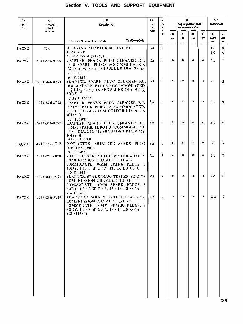
d. Tools and Support Equipment-Section V. Alist of operating tools and support equipmentauthorized at the organizational level for use byspark plug cleaner and tester operator and crew.
e . F e d e r a l S t o c k N u m b e r a n d R e f e r e n c eNumber Index-Section VI. A list. in ascendingnumerical sequence, of all Federal stock numbersappearing in the listings, followed by a list, inalphanumerical sequence, of all reference numbersappearing in the listings. Federal stock numbersand reference numbers are cross-referenced to eachillustration figure and item number appearance.
D-3. Explanation of Columns. The followingprovides an explanation of columns found in thetabular listings.
a. Source, Maintenance, and RecoverabilityCodes (SMR). SMR codes are assigned in ac-cordance with instructions contained in AR 700-18ant] AR 700-82.
(1) Source code. The source code is a twoposition alphabetical code assigned to supportitems. They are entered in the first and secondposit ion of the SMR code. They indicate themanner of acquiring support i tems for main-tenance, repair, or overhaul of end item. Followingare authorized source codes:Code Explanation
PA Item procured and stocked for anticipated orknown usage.
CodePB
PC
KD
KF
KB
PD
PE
PF
MO
MF
MH
MD
AO
Explanation
Item procured and stocked for insurance purposes
because essentiality dictates that a minimum
quantity be available in the supply system.
(a) Items to be designated as insurance items
must meet all the following criteria:
1. No failure is predicted and no demand can
be predicted based upon the planned operational
usuage.
2. The lack of a replacement item or inability
to obtain the item from procurement in a
reasonable time would seriously hamper the
operational capability of an end item or system.
3. Item cannot be manufactured by the
supporting depot facility within a reasonable time.
(b) Repair parts procured as insurance items
will normally be stocked only in CONUS depot.
As an exception, insurance items selected as an
ERPSL item may be stocked in oversea theater
depots when the theater commander determines
that they are necessary to maintain an acceptable
level of system readiness.
Item procured and stocked and which otherwise
would be coded “PA” except that it is
deteriorative in nature.
An item of depot overhaul/ repair kit and not
purchased separately. Depot kit defined as a kit
that provides items required at the time of
overhaul.
An item of a maintenance kit and not purchased
separately. Maintenance kit defined as a kit that
provides an item that can be replaced at
organizational or intermediate (DS or GS) Icvcts
of maintenance.
Item included i n both a depot overhaul/ repair
kit and a maintenance kit.
Support item, excluding support equipment,
procured for initial issue or outfitting and stocked
only for subsequent or additional initial issues or
outfitting. Not subject to automatic replenish-
ment. Use for establishing Modification Kits.
Support equipment procured and stocked for
initial issue or outfitting to specified maintenance
repair activities.
Support equipment which will not be stocked but
which will be centrally procured on demand.
Item to be manufactured or fabricated at
organizational level.
Iterm to be manufactured or fabricated at Direct
Support level.
Item to be manufactured or fabricated at General
Support level.
I t e m to be manufactured or fabricated at Depot
Maintenance level .
Item to be assembled at organizational level.
D-1
D-2
Code Explanation
AF Item to be assembled at Direct Support level.AH Item to be assembled at General Support level.AD Item to be assembled at Depot Maintenance level.XA Item is not procured or stocked because the
requirements for the item will result in thereplacement of the next higher assembly.
XB Item is not intended for procurement and is notstocked. If not available thru salvage, requisition.
XC Installation drawing, diagram, instruction sheet,field service drawing, that is identified bymanufacturers part number.
Note: Cannibalization or salvage may be used as a source ofsupply for any items source coded above except those codedXA and aircraft support items as restricted by AR 700-42.
(2) Maintenance code. The maintenancecode is a two position alphabetical code designed toindicate the levels of maintenance authorized toU S E and R E P A I R support items. They are
entered in the third and fourth position of the SMRcode.
(a) USE code. The USE code will indicatethe lowest maintenance level authorized to remove.replace, and use the support item. The decision tocode the item for removal and replacement at theindicated maintenance level will require that allcapabilities necessary to install and insure properoperation after installation of a replacement item(i.e., pre-installation inspection, testing and post-installation checkout) are provided. This code willindicate one of the following levels of maintenance:
Code ExplanationC Used to denote crew or operator maintenance
performed within Organizational level of main-tenance.
0 Support item is removed, replaced, used at theOrganizational level of maintenance.
F Support item is removed, replaced, used at theDirect Support level of maintenance.
H Support item is removed, replaced, used at theGeneral Support level of maintenance.
D Support item is removed, replaced, used at theDepot level of maintenance only.
(b) R E P A I R code. T h e R E P A I R c o d ewill indicate wheteher the item is to be repaired andidentifies the lowest maintenance level with thecapability to perform complete repair (i. e., allauthorized maintenance functions). The decision tocode the support item for repair at the indicatedmaintenance level requires that all maintenancecapability (remove, replace, repair, assemble, andtest) for the support items be provided to that level.This does not preclude some repair which may beaccomplished at a lower level of maintenance.Codes are as follows:CodeO
F
D-2
ExplanationThe lowest maintenance level capable of completerepair of the support item is the Organizationallevel.The lowest maintenance level capable of completerepair of the support item is the Direct Supportlevel.
Code Explanation
H The lowest maintenance level capable of completerepair of the support item is the General Supportlevel.
D The lowest maintenance level capable of completerepair of the support item is the Depot level.
Z Non-reparable. No repair is authorized.
(3) Recoverability code. The recoverabilitycode is a one position alphabetical code designed toindicate when the responsible Army activity desiresthe return of unserviceable repair parts and / ortools and
CodeZ
F
H
D
L
A
test equipment. Codes are as follows:
ExplanationNon-reparable item. When unserviceable, con-.demn and dispose at the level authorized toreplace the item.Reparable item. When uneconomically reparable,condemn and dispose at Direct Support level.Reparable item. When uneconomically reparable,condemn and dispose at General Support level.Reparable item. When beyond lower level repaircapability, return to Depot. Condemnation anddisposal not authorized below Depot level.Reparable item. Repair, condemnation anddisposal not authorized below depot /’ specializedrepair activity level.Item requires special handling or condemnationprocedure because of specific reasons (i.e.,precious metal content, high dollar value, criticalmaterial, or hazardous material).
b. Federal Stock Number. Indicates the Federalstock number assigned to the item and will be usedfor requisitioning purposes.
c. Description. Indicates the Federal item nameand a minimum description required to identify theitem. The last line indicates the reference numberfollowed by the applicable Federal Supply Code forManufacturer (FSCM) or Federal Supply Code fornonmanufacturers (FSCNM) in parentheses. TheFSCM and FSCNM are used as elements in itemident i f i ca t i on t o des ignate manufac turer o rdistributor or Government agency, etc., and isidentified in SB 708-42 or SB 708-82 C8.
d. Unit of Measure (U/M). Indicates thestandard or basic quantity by which the listed itemis used in performing the actual maintenancefunction. This measure is expressed by a two-
. .character alphabetical abbreviation, e.g., ea, in., pr,etc., and is the basis used to indicate quantities andallowances in subsequent columns. When the unitof measure differs from the unit of issue, the lowestunit of issue that will satisfy the required units ofmeasure will be requisitioned.
e. Quantity Incorporated in Unit. Indicates thequantity of the item used in the breakout shown onthe illustration figure,. which is prepared for afunctional group, subfunctional group, or anassembly. A “V” appearing in this column in lieu ofa quantity indicates that no specific quantity isapplicable, e.g., shims, spacers, etc.
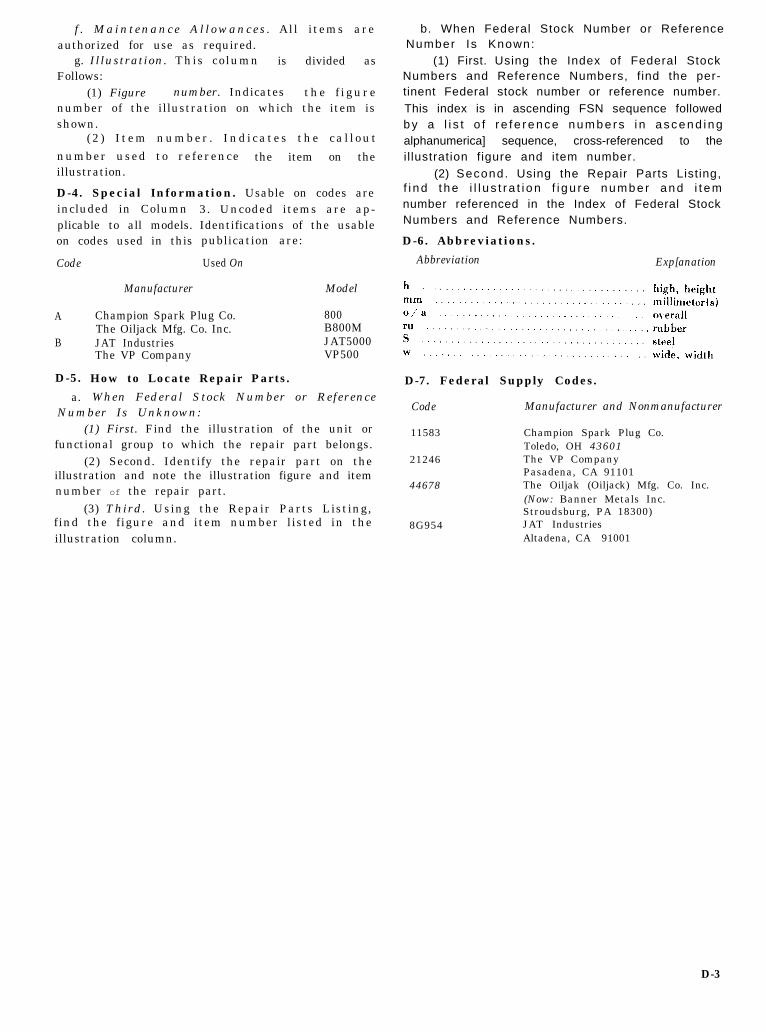
f . Maintenance A l lowances . All items areauthorized for use as required.
g. Illustration. This column is divided asFollows:
(1) Figure number. Indicates the f i gurenumber of the illustration on which the item isshown.
(2 ) I t em number . Ind i ca tes the ca l l ou t
number used to reference the item on theillustration.
D-4. Special Information. Usable on codes areincluded in Columnplicable to all models.on codes used in this
Code
A
B
D-5.
a.
Manufacturer
3. Uncoded items are ap-Identifications of the usablepublication are:
Used On
Model
Champion Spark Plug Co. 800The Oiljack Mfg. Co. Inc. B800MJAT Industries JAT5000The VP Company VP500
How to Locate Repair Parts.
When Federal Stock Number or ReferenceNumber Is Unknown:
(1) First. Find the illustration of the unit orfunctional group to which the repair part belongs.
(2) Second. Identify the repair part on theillustration and note the illustration figure and itemnumber of the repair part.
(3) Third. Using the Repair Parts Listing,find the figure and item number listed in theillustration column.
b. When Federal Stock Number or ReferenceNumber Is Known:
(1) First. Using the Index of Federal StockNumbers and Reference Numbers, f ind the per-tinent Federal stock number or reference number.This index is in ascending FSN sequence followedb y a l i s t o f r e f e r e n c e n u m b e r s i n a s c e n d i n galphanumerica] sequence, cross-referenced to theil lustration figure and item number.
(2) Second. Using the Repair Parts Listing,f i nd t he i l l u s t r a t i on f i gu re numbe r and i t emnumber referenced in the Index of Federal StockNumbers and Reference Numbers.
D-6. Abbreviations.
Abbreviation Exp[anation
D-7. Federal Supply Codes.
Code Manufacturer and Nonmanufacturer
11583 Champion Spark Plug Co.Toledo, OH 43601
21246 The VP CompanyPasadena, CA 91101
44678 The Oiljak (Oiljack) Mfg. Co. Inc.(Now: Banner Metals Inc.Stroudsburg, PA 18300)
8G954 JAT IndustriesAltadena, CA 91001
D-3
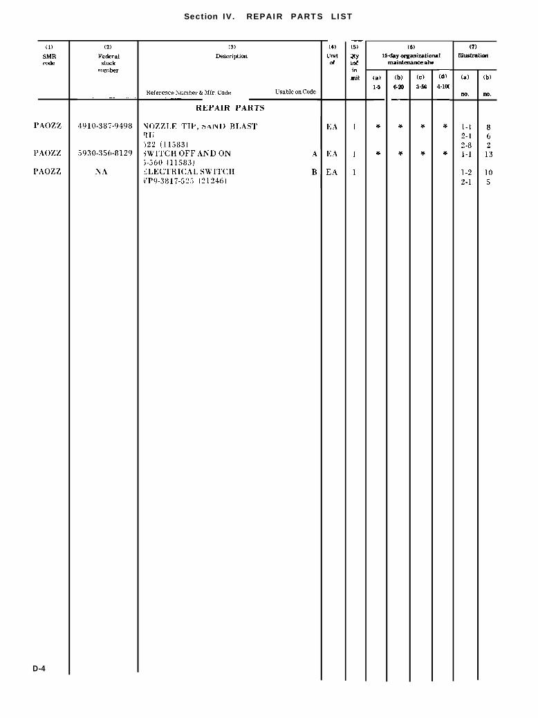
Section IV. REPAIR PARTS LIST
(1)
SMRcode
PAOZZ
PAOZZ
PAOZZ
D-4
(2)
Federalstock
number
. ..— —. —— .,
4910-387-9498
5930-356-8129
NA
(3)
Description
Reference Number & Mfr. Code Usable on Code. ..—.
REPAIR PARTS
YOZZLE TIP, aAIN~ BLASTRuj22 (11583)jWITCH OFF AND ON A;-560 (11583)3LECTR1CAL SWITCH BkJP9-3817-525 (21246)
ARNG: State AG (3); Units- Same as Active Army except allowance is one (1) copy each.USAR: Same as Active Army.For explnation of abbreviations used, see AR 310-50.
Units org under fol TOE: -2 ea.1-167 921-177 961-2073-5005-1655-1675-2785-3465-5007-1578-1238-2048-5518-5648-5658-5668-5718-5818-5908-62010-9410-50012-5612-5802929-11229-13929-40729-50231-10131-10539-514444-855-540
This fine document...
Was brought to you by me:
Liberated Manuals -- free army and government manuals
Why do I do it? I am tired of sleazy CD-ROM sellers, who take publicly available information, slap “watermarks” and other junk on it, and sell it. Those masters of search engine manipulation make sure that their sites that sell free information, come up first in search engines. They did not create it... They did not even scan it... Why should they get your money? Why are not letting you give those free manuals to your friends?
I am setting this document FREE. This document was made by the US Government and is NOT protected by Copyright. Feel free to share, republish, sell and so on.
I am not asking you for donations, fees or handouts. If you can, please provide a link to liberatedmanuals.com, so that free manuals come up first in search engines:
<A HREF=http://www.liberatedmanuals.com/>Free Military and Government Manuals</A>