Copyright 2009 California Institute of Technology. Government sponsorship acknowledged.Copyright 2009 California Institute of Technology. Government sponsorship acknowledged.
DEPLOYABLE ANTENNA STRUCTURES TECHNOLOGIES
Robert E. Freeland
Richard G. HelmsJet Propulsion Laboratory (JPL)
California Institute of Technology
November 10 - 11, 2008
Large Space Apertures Workshop
California Institute of Technology
Pasadena, California
Copyright 2009 California Institute of Technology. Government sponsorship acknowledged.
Mechanical Structures Technology History Initial Concepts for Very Large Space Antennas
• Self-Deployable• On-Orbit Assembly• On-Orbit Manufacturing & Assembly• Concept Development Limitations
Current Self-Deployable Antenna Concepts• State-of-the Art Examples• ISAT Mechanical Concept Developments
• Harris PAFR Concept, AstroFold Truss Inflatable Antenna Concepts Development
Examples Inflatables Technology Maturity Issues
Next Generation Technology Large Space Structures Technology Dev. Challenges
OUTLINE
Copyright 2009 California Institute of Technology. Government sponsorship acknowledged.
Size matters!!
EARLY INNOVATIVE CONCEPTS FOR VERY LARGE SPACE STRUCTURES
Copyright 2009 California Institute of Technology. Government sponsorship acknowledged.
Basic deployment classes of large space structures:
• Self-deployable– Mechanical– Rigidizable/Inflatable (R/I))– Hybrid
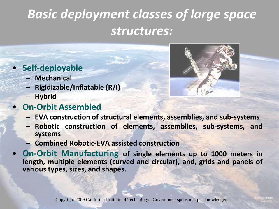
• On-Orbit Assembled– EVA construction of structural elements, assemblies, and sub-systems– Robotic construction of elements, assemblies, sub-systems, and
systems– Combined Robotic-EVA assisted construction
• On-Orbit Manufacturing of single elements up to 1000 meters inlength, multiple elements (curved and circular), and, grids and panels ofvarious types, sizes, and shapes.
R. Freeland / R. Helms
08/04/05Copyright 2009 California Institute of Technology. Government sponsorship acknowledged.
Box Truss Antenna
(100m dia.)
Detail:
• Martin Co. 1970’s Study
• Synchronized self-deployment
• One shuttle load.
• Metallic mesh reflector
• Surface shaping cable system
• Telescoping feed booms
Copyright 2009 California Institute of Technology. Government sponsorship acknowledged.
Synchronously Deployed Truss Antenna (100m size range)
Detail:
• LMSC 1965 Study for LaRC
• New, totally self-deployed approach
• One shuttle load.
• Metallic mesh reflector
• Deployable feed boom
Copyright 2009 California Institute of Technology. Government sponsorship acknowledged.
On-Orbit Robotic/EVA Assemblyfor Very Large Space Structures
Copyright 2009 California Institute of Technology. Government sponsorship acknowledged.
Nestable Columns
Underwater Truss Assembly
Detail:
• LaRC Nestable Column concept
• Marshall SFC 0-g tank
• Largest space structure assembled
using this concept
• Very long truss structure
Copyright 2009 California Institute of Technology. Government sponsorship acknowledged.
Boeing HF Space Antenna:
On-Orbit Assembly (33m dia.)
Detail:
• Launched in “kit” form for low orbit assembly
• One Shuttle flight
• Graphite/Epoxy structural elements
• RF up to 300 GHz / active
• High precision doubly curved gores with actuator(s)
• Robotically assembled
Copyright 2009 California Institute of Technology. Government sponsorship acknowledged.
Automated Orbital Modular Assembly
(100m class antenna)
Detail:
• 1970 (timeframe) General Dynamics study for LaRC
• Concept for one Shuttle bay load
• Automated modular assemble of self-deployable modules
Copyright 2009 California Institute of Technology. Government sponsorship acknowledged.
On-Orbit Manufacturing & Assemblyfor Very Large Space Structures
Copyright 2009 California Institute of Technology. Government sponsorship acknowledged.
Grumman Orbital Construction Demonstration Antenna (100m dia.)Manufacture of Ribs and Structural Elements
Detail:
• JSC sponsored study (late 1970’s)
• Orbital manufacture of composite ribs and rings
• “Turntable” fixture automated assembly operation
• Central Astromast (deployable) with RF mesh reflector (EVA)
• Tension cables EVA assembled
Copyright 2009 California Institute of Technology. Government sponsorship acknowledged.
Orbital Manufacturing and Assembly of a Very Large Reflector Antenna Structure
• On the order of 100’s meters
• Manufacturing and EVA controlled robotic assembly
• Robotic assembly of pre-fabricated precision reflector panels
Copyright 2009 California Institute of Technology. Government sponsorship acknowledged.
Concept Development Limitations
• Unfortunately, a lagging interest in going beyond the stage of“conceptual definition” primarily due to the “astronomical”costs of advancing the technologies to near flight readiness(especially on-orbit assembly and manufacturing) resulted invery little significant development.– $100’s millions spent on various concepts and ground demos
• This unfortunate turn of events left only self-deployablestructures technologies as a viable candidate for limitedapplications:– Started out with small size structures that lent themselves to meaningful
ground-based evaluation
– Over a period of time (~ 50 yrs.) self-deployables advanced tocapabilities for 30 meter structures, mainly antennas.
R. Freeland / R. Helms
08/04/05
Current State of the Art for Mechanical Self-Deployables
Copyright 2009 California Institute of Technology. Government sponsorship acknowledged.
ATS – 6
Wrap-Rib
Antenna (9.5 m)
Detail:
• Lockheed: first flown in 1960’s
• Aluminum ribs
• Copper-coated Dacron mesh
• Deployed using strain energy release
Copyright 2009 California Institute of Technology. Government sponsorship acknowledged.
Lockheed LSST:
Wrap-Rib Antenna
(sector of 55m dia.)
Detail:
• Graphite/Epoxy lenticular ribs
• Gold plated Molybdenum wire mesh
• Kinematic deployment demo
• RF up to 3 GHz
• Intended operational size: 110 meters
Harris Mesh
Reflector Antennas
Copyright 2009 California Institute of Technology. Government sponsorship acknowledged.
HARRIS TDRSS ANTENNA
(6 meters)
Detail:
• NASA sponsored concept development
• Early 1960’s
• Radial rib development
• First “tunable” mesh reflector
• RF up to Ku band
• Basic concept flown at 6+ meters
Copyright 2009 California Institute of Technology. Government sponsorship acknowledged.
Detail:
• Harris Corp
•Folding radial rib mesh reflector
• Flown at 12 meter diameter
• Adjustable mesh aperture
• RF compatibility to 10 GHz
• Reflector rim support capability
• 1990’s
Copyright 2009 California Institute of Technology. Government sponsorship acknowledged.
Japanese VSOP VLBI Antenna
Detail:
• 10 meter diameter
• Metallic mesh reflector
• Radial deployment rib system
• Surface shaping net
• Designed for 21 GHz
• Orbital performance 5 GHz
• 1990’sCopyright 2009 California Institute of Technology.
Government sponsorship acknowledged.
TRW Astro Aerospace
Thuraya AstroMesh
12.25-meter Reflector
Customer: HughesTRW Astro Aerospace patented design
U.S. Patent No. 5,680,145
Copyright 2009 California Institute of Technology. Government sponsorship acknowledged.
AR
RA
Y L
EN
GT
H
(me
ters
)
DEPLOYABLE SPACE ANTENNA STRUCTURES
9
616 10
4 75
3,8,
13
1 16
2
14 1211
15
MESH ANDINFLATABLE
DEPLOYABLES
FREQUENCY – GHz
10 20 30 40 50 60
50
40
30
20
10
0
SOLIDELEMENTDEPLOYABLE
SOLID REFLECTORS
1. ATS-62. TDRSS3. SEASAT-A4. JERS-1
5. ERS-16. ALMAZ-17. OKEAN8. USSR VLBI
9. ZNAMYA10. IAE13. M-SAT
CONCEPTS FLOWN
CONCEPTS UNDER DEVELOPMENT
14. PAMS15. HARD
16. ASTROMESH
CONCEPTS TO BE FLOWN
11. VSOP
12. RADIOASTRON
17. RADARSAT
17
15
Copyright 2009 California Institute of Technology. Government sponsorship acknowledged.
HARRIS ISAT PAFR
Elastic Strain Energy Hinges
Tapered Longeron Tubes
Sequential Forming
of Strongback Bays
Surface Cord Truss
Folding/Telescoping Compression Strut
Mesh Management
Synchronized Reflector Deployment
Sequential Tensioning of Reflector
Strongback Diagonal
Folding Elevator Screws
Reflector End
Conditions
Passive Unfolding
of Feed Panels
Stowage of Feed Panels
Copyright 2009 California Institute of Technology. Government sponsorship acknowledged.
INFLATABLE ANTENNA CONCEPT DEVELOPMENT
FOR VERY LARGE SPACE STRUCTURES
Copyright 2009 California Institute of Technology. Government sponsorship acknowledged.
HISTORY of
INFLATABLE SPACE STRUCTURES
A wide variety of inflatable space structures have been evaluated
over the last 50 years.
It has only been recently that the mechanical performance potential has
been recognized.
Early technology advancements were derived primarily from
hardware demonstrations.
Early concept developments were critically limited by “off-the-shelf” thin
film that had handling, processing, and fabrication issues.
Although it was recognized early that there was a need for in-situ space
rigidizable structures, it wasn’t until the 1980’s that the materials began
to be available.
Copyright 2009 California Institute of Technology. Government sponsorship acknowledged.
ECHO BALLOONS
Flown August 1960
NASA LaRC/GSFC/General Mills/Sheldahl
Echo I Successfully Flown August 12, 1960
Passive, Space Based Commun. Reflectors
100 Ft. Dia. /136 lbs/ 26 in Dia. Stowed Container
Multiple, 12 m Aluminized Mylar Gores
Ballistic Flights Validation/Mechanical
Packaging/Ejection/Inflation
Delta Launch Vehicle/1000 km Orbit
Operational for Months
Significance of Development
Technology Development
Large Area Thin Film
Handling/Processing/Fabrication/Assembly
Orbital Deployment by Inflation
Mechanical Packaging
Launch Restraint/Release
Vacuum Packaging Techniques
Metalized Thin Film
Operational Inflatable Space Structure
First Successful Large Size, High Prec.
Inflatable Space Structure on Orbit
History of
SPACE INFLATABLE STRUCTURES
Copyright 2009 California Institute of Technology. Government sponsorship acknowledged.
LENTICULAR INFLATABLE
PARAGORIC REFLECTOR
Technology Demonstration/Late 1950’s
Good Year
12 Meter Diameter Reflector Support Structure
10 Meter Lenticular Reflector
Multiple Gore Reflector/Canopy Construction
Multiple Element Torus
Metalized Membrane for RF Reflectivity/Solar
Energy Collection
Foam Rigidization Techniques Evaluated
Significance of Development
Technology Development
Thin Film Handling/Processing/Fabrication
Inflatable Element Assembly/Alignment
Deployment By Inflation
Metalization of Thin Film
Mechanical Packaging Techniques
First Large Size Precision Inflatable Reflector
Structure
History of
SPACE INFLATABLE STRUCTURES
Copyright 2009 California Institute of Technology. Government sponsorship acknowledged.
INFLATABLE SEARCH RADAR ANTENNA
Technology Demonstration/Late 1950’s
Good Year
10 x 2 Meters
Truss Support Structure
Metallic Mesh Aperture
Parabolic Reflector Surface
Packaging Based on “Stacking” of 6 to 8 Flat Panels
Significance of Development
Technology Development
Multiple Structural Element Fabrication
Inflatable Element Assembly/Alignment
Mesh/Support Structure Interface
Deployment by Inflation
Mechanical Packaging Techniques
First Large Size Precision Inflatable Truss Structure
History of
SPACE INFLATABLE STRUCTURES
Copyright 2009 California Institute of Technology. Government sponsorship acknowledged.
INFLATABLE EXO-ATMOSPHERIC OBJECT
Flown Late 1960’s
L’Garde, Inc.
Successfully Flown During the Late 1960’s
Re-Entry Vehicle Decoys/Single Structure Flights
Size Range 1 by 2 Meters/100,000 Ft. Orbit
On Board Down Link
Configured to Simulate Pitch/Roll of Re-Entry
Vehicle
Simulated Radar / IR Signature
Inflation Milli Seconds
Materials EPDM / Nomex/Carbon Fiber
Significance of Development
Technology Development
Thin Film Handling/Processing/Manufacturing/Assem.
Residual Air Management
Packaging/Launch Release
On Orbit Deployment by Inflation
Miniaturized Inflation System
Metalized Flexible Materials
First Successful Flight of “Shaped” Inflatable Space
Structures
Fully Instrumented Thin Membrane Structures
History of
SPACE INFLATABLE STRUCTURES
Copyright 2009 California Institute of Technology. Government sponsorship acknowledged.
LAND MOBILE COMMUNICATIONS
REFLECTOR ANTENNA
Technology Demonstration/1980’s
Contraves Space Division/ESA
10 x 12 Meter Offset Reflector Antenna Structure
Surface Precision/Non-Rigidized/2 mm rms
Multiple Gore Reflector Structure/Torus Support
Structure
Reflector/Canopy/Torus Structure Rigidized By
Solar Heating
Estimates of Orbital Mechanical Performance
Significance of Development
Technology Development
Rigidization of Flexible Materials Concepts
Handling/Processing/Fabrication of Rigidizable
Materials
Inflatable Element Assembly/Alignment
Deployment by Inflation
Metalization of Rigidizable Materials
Mechanical Packaging Techniques
First Large Inflatable Rigidizable Reflector
Structure
History of
SPACE INFLATABLE STRUCTURES
Copyright 2009 California Institute of Technology. Government sponsorship acknowledged.
INFLATABLE VERY LONG BASELINE
INTERFEROMETRY ANTENNA
Technology Demonstration/1980’s
Contraves Space Division/ESA
6 Meter Diameter/Axi-Symmetric Reflector
Surface Precision/Non-Rigidized on the order of
mm rms
Multiple Gore Reflector Structure/Torus Support
Structure
Reflector/Canopy/Torus Structure Rigidized
Estimates of Orbital Mechanical Performance
Intended for 21 Ghz RF Operation
Significance of Development
Technology Development
Rigidization of Flexible Materials Concepts
Handling/Processing/Fabrication of Rigidizable
Materials
Inflatable Element Assembly/Alignment
Deployment By Inflation
Metalization of Rigidizable Materials
Mechanical Packaging Techniques
First Large Size Inflatable Rigidizable Reflector
Structure
History of
SPACE INFLATABLE STRUCTURES
Copyright 2009 California Institute of Technology. Government sponsorship acknowledged.
INFLATABLE ANTENNA EXPERIMENT
Flown Late 1996
L’Garde, Inc./NASA/JPL
IAE Successfully Flown May 29, 1996
Large Inflatable Antenna Structure Technology
Demonstration
Reflector Structure 14 Meters/Strut Structure 28 Meters
Flown on STS Spartan 77/Recoverable Spacecraft
Spacecraft/Experiment One Orbit
Demonstrations/Low Cost Structure Hardware/High
Mechanical Packaging Efficiency/Deployment
Reliability/Large High Precision Membrane Reflector
Manufacturing
Significance of Development
Technology Development
Large Size Complex Inflatable Structural Element
Handling/Processing/Fabrication
Manufacturing Validation
Large Size Structural Element Assembly/Alignment
Mechanical Packaging/Launch Restraint
On Orbit Deployment by Inflation
First Large Size Reflector Structure Deployed on Orbit
Ground-based Surface Precision Measurement
History of
SPACE INFLATABLE STRUCTURES
Copyright 2009 California Institute of Technology.
Government sponsorship acknowledged.
IAE Reflector Structure (15m)
Detail:
• NASA sponsored L’Garde, Inc. reflector
• Flight Hardware.: inflated lenticular reflector
• Inflated perimeter truss supported
• Reflector Membrane: 7 µm Mylar/Aluminum coated
• 62 gore aperture with 4 mm RMS figure
Copyright 2009 California Institute of Technology. Government sponsorship acknowledged.
IAE Deployed On-Orbit
(30m struts)
Detail:
• Neoprene struts 14 inches in dia.
• Spartan carrier was STS retrievable
• Drag stabilized in Shuttle orbit
• One orbit experiment
• Antenna structure ejected
Copyright 2009 California Institute of Technology. Government sponsorship acknowledged.
Recent Interest in Inflatable Structures Technology
for 300 Meter Antennas
Copyright 2009 California Institute of Technology. Government sponsorship acknowledged.
Task Purpose/Objectives:
• Establish the suitability of the new inflatable space
structures technology for a class of large reflector
radar antenna concepts
Major Products:
• Large Inflatable Deployable Radar Antenna
Concept Definition
• Advanced Concept Development for the Space
Based Rigidization of Flexible Materials
• Inflatable Truss/Mesh-Net Integration
(Picture)Net
Mesh
Perimeter Truss
Tie Elements
Net
• Axi-Symmetric
• 10 GHz RF Operation
• High Orbit Operation
• Diameter: 25 Meters
• Surface Accuracy: l/16 RMS
• Multiple Feed Element Support Structure
Potential Cost Advantages:
• High antenna stowed packaging efficiency allowing
the use of smaller fairings and launch vehicles
• Conformable stowed geometries enabling a wide
spectrum of height and width variations
• Application specific weight savings as much as 3:1
• Antenna hardware cost reduction greater than 10:1
BASELINE: INFLATABLE STRUCTURE/NET- MEMBRANE ANTENNA
LARGE RADAR ANTENNA PROGRAM (LRA)
Copyright 2009 California Institute of Technology. Government sponsorship acknowledged.
.
TECHNOLOGY DEVELOPMENT AND APPLICATION ENABLING
LARGE INFLATABLE ANTENNAS
1999 2000 2001 2002 2003 2004 2005
2 3 4+ 5 6+ 7,8 9
TECHNOLOGY READINESS LEVELS
30M Flight Unit Integration & Launch
ANTENNA SYSTEM INTEG. & LAUNCH
FLIGHT PERFORMANCE
VALIDATION
• Inflatable Truss Design Refinement
• Surface Shaping Techniques
• Est. of Functional Mechanical Performance
• 14M Deployment Control, Mech. Packaging, Ascent Venting
• Test Techniques
ANTENNA DESIGN
30M Antenna Detail Design
• Flight Test Evaluation
• Concept Evaluation Results
• Functional Performance Req.
14M Antenna Engineering Model
• Analytical Model Validation
• Ground Based Validation
Truss Element Flight Test
6M Concept Evaluation Scale Hdw.
BASIC TECHNOLOGY EVALUATION
• 6M. Struct./Mech/Thermal Testing
• Initial Geometry/Geometric Precision
• Kinematic Function Testing
• Deployment Control
• Deployed Stiffness 30M Flight Hdw. Fab., Assembly, Functional Testing & Feed System Integration
Launch Vehicle Interface
• Design Validation Techniques
• Assembly Techniques/Handling
• Ground Test Techniques
FLIGHT HDW. FAB,
ASSEMBLY, & TEST
30M Antenna Configuration Design
Rigidized Materials Candidates
Mesh Shaping System Candidates
Structural Models
Truss Element Experiment Design
• Rigidized Materials Concepts
• Truss Joints Concepts
• Analytical Simulations
• Rigidized Structural Elements
• Truss Joint Design
• Projections of Truss Performance
• Surface Precision Techniques
Phase II Study Results30 M Antenna Conceptual
Design Inflatable Perimeter Truss Mesh Surface Shaping System
BASIC TECHNOLOGY
ADVANCEMENT
FEASIBILITY ASSESSMENT
STUDY
Copyright 2009 California Institute of Technology. Government sponsorship acknowledged.
Program Objectives:
• To assess the risk associated with the integration of
rigidizable/inflatable antenna structures technologies
with ISAT radar antenna designs
Major Technical Tasks:
• Candidate Baseline Truss Concept Design(s)
• Focused Mechanical Modeling & Experimentation
• High-Fidelity Steady State & Transient
Simulations
Accomplishments:
• Early LRA developments led to significant enabling RI
materials technologies
• Gov. baseline highly instrumental in calibrating and
validating vendor radar antenna design performance
• Established one-of-a-kind statistical RI mechanical
properties test database along with the corresponding
constitutive correlations
• Hybridized analysis techniques developed
• Enabled NASA Technology Readiness Levels to
establish RI Tech. Risk Assessment and Mitigation
FY’02-’04 ISAT RI RISK ASSESSMENT & MITIGATION PROGRAM SUMMARY
Representative GMTI Antenna System Concepts
Performance Requirements:
• Baseline Option:
•Truss Length 300 Meters
• 10 GHz RF Operation
• MEO Operation
• Truss Bay Depth 3 Meters
• Multiple Active RF Panels
• Alignment Precision TBD Meters
GMTI Space-Based Radar Antenna: Triagonal bay
antenna support structure
RIGIDIZABLE/INFLATABLE SPACE STRUCTURES TECHNOLOGY
Copyright 2009 California Institute of Technology. Government sponsorship acknowledged.
.
1996 / / 2001 2002 2003 2004 2005 2006 / / 2009 / / 2012
ISAT
DARPA/STO INNOVATIVE SPACE-BASED RADAR ANTENNA TECHNOLOGY
(ISAT) PROGRAM PLAN
Phase II
Industry Design Competition
Phase III
Flight Demo System
Phase IV
Operational System Concept
Phase I
“Seedling” Tech. Studies
NRO
NASADARPA
• Industry Radar Antenna Design Development
• PDR Downselect
• CDR Final Selection
• Radar Antenna Technology Flight Demo
DARPA
Rigidizable/Inflatable Technologies
Risk Assessment & Mitigation
100 Meter
300 Meter
Perimeter
Truss / Mesh-
Net
Integration LRA
Configuration
Design
Copyright 2009 California Institute of Technology. Government sponsorship acknowledged.
INFLATABLE ANTENNA TECHNOLOGY MATURITY ISSUES
The applicability of the R/I technology for specific mission types is a
function of the maturity of the basic elements and their effective
interactions.
The maturity of each element is a function of the challenge of the
specific mission application with the potential of a large range of
maturity levels among the elements.
In the last ten years there has been significant advancements in certain
technology elements.
Currently, the most significant issue (and potential “show-stopper”) is
the lack of workable concepts for simple and reliable deployment
control cages.
A concerted design effort and investment is required to extensively
modify and/or develop new basic technology elements.
Copyright 2009 California Institute of Technology. Government sponsorship acknowledged.
BASIC INFLATABLE STRUCTURES TECHNOLOGY ELEMENTS
Materials Rigidization Concepts
Deployment Control Techniques
Mechanical Packaging Techniques
Ascent Venting Approaches
Launch Restraint/Release Techniques
Analytical Simulation/Deployment/Operational Performance
Space Durable Flexible Materials
Thin Film/Handling/Processing/Fabrication
Manufacturing Quality Verification
Assembly/Alignment/Verification
Ground Based Deployment Test Techniques
Ultra Light/On Orbit Gas Generation & Pressure Control
Copyright 2009 California Institute of Technology. Government sponsorship acknowledged.
Next Generation TechnologyCopyright 2009 California Institute of Technology. Government sponsorship acknowledged.
Copyright 2009 California Institute of Technology. Government sponsorship acknowledged.
“One-g” laboratory environment Sag Kinematic friction and lock-up due to mechanical loading Poor repeatability and non-linear motions Non-representative initial and boundary conditions
Limited facilities large enough to test structure and itsdeployment
Conventional structural and dynamic validation tests difficultto perform
Thermal simulation and control issues Test/analysis correlation for on-orbit performance increasingly
limited to structural sub-systems, components, and elements.
THE LIMITATIONS Of GROUND TESTING LARGE SPACE STRUCTURES
Copyright 2009 California Institute of Technology. Government sponsorship acknowledged.
Risks associated with not performing adequate ground testing:
Poor validation of on-orbit structural anddeployment performance
Limited demonstration of functional behavior Test/analysis correlation compromised
RISKS
Conclusions for very large orbiting sensor
structures…in general
• Based on the current trends in requirements, the limitations of the state-of-
the-art technologies, and the high potential of some of the early concepts,
the application of old, current, and new technologies for future very large
space structures is clearly suggested.
• The potential of any combination of these technologies is proportional
to the maturity of each and every element, and their compatibility with
each other.
• A possible scenario based on such an approach would be the automated
orbital assembly of a small number of flight proven sub-systems to achieve
a substantial (large, high-precision) full-up operational system.
• Example: self-deployable modules (80-100 meters) based on repeated
segments that lend themselves to “simple” orbital assembly that could
potentially create a structure in the 300-600 meter size range.
R. Freeland / R. Helms
08/05/05Copyright 2009 California Institute of Technology. Government sponsorship acknowledged.
Automated Orbital Modular Assembly
(100m class antenna)
Detail:
• 1970 (timeframe) General Dynamics study for LaRC
• Concept for one Shuttle bay load
• Automated modular assemble of self-deployable modules
Copyright 2009 California Institute of Technology. Government sponsorship acknowledged.
ELECTRONICALY SCANNED PLANAR ARRAY ANTENNACopyright 2009 California Institute of Technology. Government sponsorship acknowledged.
Copyright 2009 California Institute of Technology. Government sponsorship acknowledged.
Back-UP Viewgraphs
Copyright 2009 California Institute of Technology. Government sponsorship acknowledged.
MODULAR ORBITAL ASSEMBLY CONCEPT
Self-deployable modules (10’s of meters) combined as repeated segments that lend themselves to “simple” automated orbital assembly with the potential to create a structure in the 300-600 meter size range
This approach has the advantage of combining previously demonstrated large antenna structures into one long continuous antenna. The complexities of testing, packaging, and launching an enormous monolithic structure are mitigated, thus reducing risk, cost, and schedule.
Copyright 2009 California Institute of Technology. Government sponsorship acknowledged.
AS 1 2 3 USP 1. SYSTEM LAUNCH CONFIGURATION
AS Assembly Station
USP Upper Stage Propulsion
1,2,3 Deployable Antenna Modules
AS 1 2 3 USP 2. DEPLOYED ASSEMBLY STATION (AS)
3. TRANSFER OF AS TO STOWED MODULES
1 2 3
AS
USP
AS
Guide Rails
Deployed
1 2 3
AS
USP 4. DEPLOYMENT OF MODULE 1
1
AS
2 3 USP 5. DEPLOYMENT OF MODULE 2
AS
1 2 3 USP 6. LINEAR TRANSFER OF AS
AS
1 2 3 USP
7. DEPLOYMENT OF MODULE 3
AS
1 2 3 USP
8. TRANSFER OF DEPLOYED STRUCTURE TO OPERATIONAL ORBIT
Position AS for
Operational
Functions
Robotic Orbital Assembly Concept
(example)
Copyright 2009 California Institute of Technology. Government sponsorship acknowledged.
MODULAR ORBITAL ASSEMBLYRisk, Cost and Schedule Advantages
Potential Risk Reduction: Ground testing limitations mitigated
Test/analysis correlation and “scaling” factors simplified
Orbital assembly risks smaller than those for launchingand deploying a large monolithic structure
Modular ground test validation with higher maturity levels
Higher aperture precision due to less tolerance build-ups
Deployment simplified through isolation of cascadingboundary conditions and single-point failures
Copyright 2009 California Institute of Technology. Government sponsorship acknowledged.
MODULAR ORBITAL ASSEMBLYRisk, Cost and Schedule Advantages (2)
Cost Reduction: Smaller sized modules have significantly less kinematic
complexity and associated costs
Smaller scope ground testing with simplified and repeatable techniques
Less technology development required when using heritage hardware
Schedule Reduction: Early structural characterization and mathematical model
verification for more realistic orbital performance predictions
The technology development planning, the contracting activities
for hardware, specialized services, and long lead time items,
will all benefit from simpler structures concept development.