DEPLOYING JOINT BEAM HOPPING AND PRECODING IN MULTIBEAM SATELLITE NETWORKS Vahid Joroughi , Eva Lagunas , Stefano Andrenacci , Nicola Maturo Symeon Chatzinotas , Joel Grotz † and Bj ¨ orn Ottersten Interdisciplinary Centre for Security, Reliability and Trust, University of Luxembourg † SES. S. A., Betzdolf, Luxembourg E-mail:{vahid.joroughi, eva.lagunas, stefano.andrenacci, symeon.chatzinotas, bjorn.ottersten}@uni.lu, [email protected]ABSTRACT This paper studies the application of Beam Hopping (BH) as a key enabler to provide high level of flexibility to manage scarce on-board resources, particularly power, based on the irregular and time variant traffic requests/demands distributed within the coverage of a satellite multibeam system. How- ever, while high throughput full frequency reuse pattern is employed among beams, the performance of BH is signifi- cantly degraded due to the generated inter-beam interference, and applying precoding is essential. In this context, we pro- pose Joint Precoding and BH (J-PBH) in a multibeam system. The proposed J-PBH has the following functionality: serving beams follows an illumination pattern where at consecutive time instants high-demand beams are served more often than low-demand beams. Then, a Zero Forcing precoding is em- ployed aiming at equalizing inter-beam interference. Conse- quently, the proposed J-PBH flexibly manage on-board power resources between high- and low-demand beams. Numerical simulations are presented which validate the proposed J-PBH benefits. 1. INTRODUCTION Glossaries (1) Demand Capacity (DC): the capacity requested by users. (2) Offered Capacity (OC): represents the maximum delivered capacity of the system. (3) Unused system Capacity (Unused-C): the difference be- tween the offered capacity and the usable system capacity. (4) Unmet capacity Demand (Unmet-D): the difference be- tween the capacity demand and the offered capacity. 1.1. Motivation Built on the MIMO framework, the use of multiple spot beams, i.e. multibeam, in modern broadband satellites have been recently considered by employing fractional frequency reuse among the beams, leading to provide higher spectral efficiency [1]. However, one of the major challenges is that adjacent beams create high levels of interference due to the side lobes of their radiation pattern on the Earth surface. To cope with this interference, denoting N c as the number of employed disjoint frequency bands among beams, a promis- ing solution is to use full frequency reuse pattern (N c = 1) by resorting to precoding in the forward link and multiuser detection in the return link [2]-[4]. Note that the performance of interference mitigation technique is sensitive to the quality of available Channel State Information (CSI) at the gateway. In addition, the precoding/detecting is realized at the gateway to guarantee low complex user terminals and payload infras- tructure. Apart from interference limitation, another major challenge is that previous and current systems have shown that in broadband multibeam satellites the demand in high- demanded beams is left unmet, i.e. Unmet-D, while capacity is left unused, i.e. Unused-C, in the low-demanded beams, leading to have an unbalance distribution of scarce on-board resources over the service coverage. Beam Hopping (BH) has been proposed as a promising technological enabler to provide a very high level of flexibility to manage irregular and time variant traffic requests in the satellite coverage area [5]-[6]. Indeed, applying BH leads to optimize the Unused-C and Unmet-D at the beams and allocate on-board resources to each beam upon its demand. However, considering full frequency reuse pattern, the performance of BH is signif- icantly degraded by inter-beam interference and applying precoding/multiuser detection is essential. 1.2. Contribution This work attempts to propose a Joint Precoding and BH (J- PBH) technique in the forward link of a multibeam system. In this context, we consider a BH managing time scheme aiming at flexibly managing on-board resources (particularly power)at the multibeam service coverage. In addition, a linear Zero Forcing (ZF) precoding scheme is designed in order to manage inter-beam interference. Moreover, we complement the design by formulating ZF precoding problem based on individual on-board per feed power constraint. This is done in order to further efficiently and more realistic use of payload power resources. This is obtained by considering the ZF and its relation to the theory of generalized inverse in the linear algebra. For the sake of relaxing computational complexity of analyzing proposed J-PBH, throughout this paper a perfect CSI is considered at the transmitting segment. The rest of the paper is organized as follows. Section II presents the signal model. The concept of generalized inverse is presented in Section III. Section IV presents precoding design. Section V provides numerical results. Finally, we derive our conclusion in Section VI. Notation: Boldface uppercase letters denote matrices and
Transcript
DEPLOYING JOINT BEAM HOPPING AND PRECODING IN MULTIBEAM SATELLITENETWORKS
Vahid Joroughi⋆, Eva Lagunas⋆, Stefano Andrenacci⋆, Nicola Maturo⋆ Symeon Chatzinotas⋆, Joel Grotz†
and Bjorn Ottersten⋆⋆Interdisciplinary Centre for Security, Reliability and Trust, University of Luxembourg
†SES. S. A., Betzdolf, LuxembourgE-mail:{vahid.joroughi, eva.lagunas, stefano.andrenacci, symeon.chatzinotas, bjorn.ottersten}@uni.lu,
This paper studies the application of Beam Hopping (BH) asa key enabler to provide high level of flexibility to managescarce on-board resources, particularly power, based on theirregular and time variant traffic requests/demands distributedwithin the coverage of a satellite multibeam system. How-ever, while high throughput full frequency reuse pattern isemployed among beams, the performance of BH is signifi-cantly degraded due to the generated inter-beam interference,and applying precoding is essential. In this context, we pro-pose Joint Precoding and BH (J-PBH) in a multibeam system.The proposed J-PBH has the following functionality: servingbeams follows an illumination pattern where at consecutivetime instants high-demand beams are served more often thanlow-demand beams. Then, a Zero Forcing precoding is em-ployed aiming at equalizing inter-beam interference. Conse-quently, the proposed J-PBH flexibly manage on-board powerresources between high- and low-demand beams. Numericalsimulations are presented which validate the proposed J-PBHbenefits.
1. INTRODUCTIONGlossaries(1) Demand Capacity (DC): the capacity requested by users.(2) Offered Capacity (OC): represents the maximum deliveredcapacity of the system.(3) Unused system Capacity (Unused-C): the difference be-tween the offered capacity and the usable system capacity.(4) Unmet capacity Demand (Unmet-D): the difference be-tween the capacity demand and the offered capacity.1.1. MotivationBuilt on the MIMO framework, the use of multiple spotbeams, i.e. multibeam, in modern broadband satellites havebeen recently considered by employing fractional frequencyreuse among the beams, leading to provide higher spectralefficiency [1]. However, one of the major challenges is thatadjacent beams create high levels of interference due to theside lobes of their radiation pattern on the Earth surface. Tocope with this interference, denoting Nc as the number ofemployed disjoint frequency bands among beams, a promis-ing solution is to use full frequency reuse pattern (Nc = 1)by resorting to precoding in the forward link and multiuserdetection in the return link [2]-[4]. Note that the performance
of interference mitigation technique is sensitive to the qualityof available Channel State Information (CSI) at the gateway.In addition, the precoding/detecting is realized at the gatewayto guarantee low complex user terminals and payload infras-tructure. Apart from interference limitation, another majorchallenge is that previous and current systems have shownthat in broadband multibeam satellites the demand in high-demanded beams is left unmet, i.e. Unmet-D, while capacityis left unused, i.e. Unused-C, in the low-demanded beams,leading to have an unbalance distribution of scarce on-boardresources over the service coverage. Beam Hopping (BH)has been proposed as a promising technological enabler toprovide a very high level of flexibility to manage irregularand time variant traffic requests in the satellite coverage area[5]-[6]. Indeed, applying BH leads to optimize the Unused-Cand Unmet-D at the beams and allocate on-board resourcesto each beam upon its demand. However, considering fullfrequency reuse pattern, the performance of BH is signif-icantly degraded by inter-beam interference and applyingprecoding/multiuser detection is essential.
1.2. ContributionThis work attempts to propose a Joint Precoding and BH (J-PBH) technique in the forward link of a multibeam system.In this context, we consider a BH managing time schemeaiming at flexibly managing on-board resources (particularlypower)at the multibeam service coverage. In addition, a linearZero Forcing (ZF) precoding scheme is designed in order tomanage inter-beam interference. Moreover, we complementthe design by formulating ZF precoding problem based onindividual on-board per feed power constraint. This is done inorder to further efficiently and more realistic use of payloadpower resources. This is obtained by considering the ZF andits relation to the theory of generalized inverse in the linearalgebra. For the sake of relaxing computational complexityof analyzing proposed J-PBH, throughout this paper a perfectCSI is considered at the transmitting segment.The rest of the paper is organized as follows. Section IIpresents the signal model. The concept of generalized inverseis presented in Section III. Section IV presents precodingdesign. Section V provides numerical results. Finally, wederive our conclusion in Section VI.Notation: Boldface uppercase letters denote matrices and
boldface lowercase letters refer to column vectors. (.)H , (.)Tdenote Hermitian transpose, transpose matrices, respectively.IN builds the N × N identity matrix. (A)i,j representsthe (i-th, j-th) element of matrix The notation diag repre-sents a diagonal matrix. Finally, E{.} and ∣∣.∣∣ refer to theexpected value operator and the Frobenius norm operators,respectively.
2. SYSTEM DESCRIPTION AND BH SCHEME
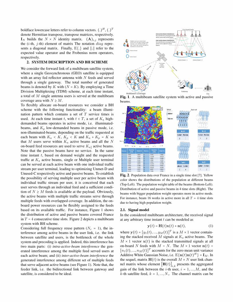
We consider the forward link of a multibeam satellite system,where a single Geosynchronous (GEO) satellite is equippedwith an array fed reflector antenna with N feeds and servedthrough a single gateway. The total number of generatedbeams is denoted by K with (N = K). By employing a TimeDivision Multiplexing (TDM) scheme, at each time instant,a total of M single antenna users is served at the multibeamcoverage area with N ≥M .To flexibly allocate on-board resources we consider a BHscheme with the following functionality: a beam illumi-nation pattern which contains a set of T service times isused. At each time instant t, with t ∈ T , a set of Ka high-demanded beams operates in active mode, i.e. illuminated-beams, and Kp low-demanded beams in passive mode, i.e.non-illuminated-beams, depending on the traffic requested ateach beam with Ka < K, Kp < K and Ka + Kp = K sothat M users serve within Ka active beams and all the Non-board feed resources are used to serve Ka] active beams.Note that the passive beams have no service. In the sametime instant t, based on demand weight and the requestedtraffic at Ka active beams, single or Multiple user terminalcan be served at each active beam with one individual trafficstream per user terminal, leading to optimizing Unmet-D andUnused-C respectively active and passive beams. To establishthe possibility of serving multiple user per active beam withindividual traffic stream per user, it is conceived that eachuser serves through an individual feed and a sufficient condi-tion of N ≥ M feeds is available at the payload. Obviously,the active beams with multiple traffic streams serve throughmultiple feeds with overlapped coverage. In addition, the on-board power resources can be flexibly assigned to the feedsbased on its available traffic. For instance, Figure 1 showsthe distribution of active and passive beams covered Francein T = 4 consecutive time slots. Figure 2 depicts a multibeamsystem with BH scheme.Considering full frequency reuse pattern (Nc = 1), the in-terference among active beams in the user link, i.e. the linkbetween satellite and users, is the bottleneck of the wholesystem and precoding is applied. Indeed, this interference hastwo main parts: (i) intra-active-beam interference the gen-erated interference among the multiple feed served users ateach active beam; and (ii) inter-active-beam interference thegenerated interference among different set of multiple feedsthat serve adjacent active beams (see Figure 1). Note that, thefeeder link, i.e. the bidirectional link between gateway andsatellite, is considered to be ideal.
Multiple user per active beam
which serve through multiple traffic
streams, one individual traffic per
user. Each user serves through an
individual on-board feed
Passive Beam
Active Beam
Multibeam coverage
N on-boardFeeds
K beams
with N=K
Gateway
City
N on-board feeds
Active beam 2 Active beam 1
Intra-active-beam interference: the interference among the feeds which serve each active beam
Inter-active-beam interference: the interference among the feeds which serve adjacent active beams
Fig. 1. A multibeam satellite system with active and passivebeams.
Beam no.Population
[x106]Weight (%) Beam no.
Population
[x106]Weight (%)
1 2.0453 1.6813 11 2.3725 1.9502
2 3.6783 3.0236 12 12.9218 10.6219
3 2.1449 1.7631 13 3.8562 3.1698
4 2.6049 2.1413 14 3.9900 3.2799
5 2.9393 2.4162 15 1.3115 1.0781
6 3.6647 3.0125 16 16.2514 13.3588
7 4.5352 3.7280 17 11.7312 9.6432
8 1.8685 1.5359 18 20.0535 16.4842
9 3.6200 2.9757 19 8.4937 6.9819
10 6.5513 5.3852 20 7.0186 5.7694
12345
6789
101112131415
1617181920
Beam no#
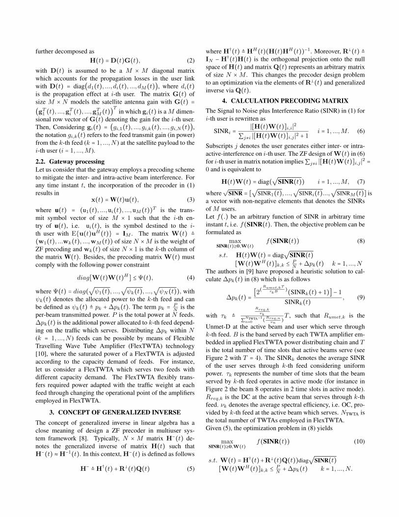
Fig. 2. Population data over France in a single time slot [7]. Yellowcolor shows the distributions of the population at different beams(Top-Left). The population weight table of the beams (Bottom-Left).Distribution of active and passive beams in 4 time slots (Right). Thebeams with bigger population weight operates more in active mode.For instance, beam 16 works in active more in all T = 4 time slotsdue to having high population weight.
2.1. Signal modelIn the considered multibeam architecture, the received signalat any arbitrary time instant t can be modeled as
y(t) =H(t)x(t) + n(t), (1)
where y(t) = [y1(t), ..., yM(t)]T is a M × 1 vector contain-ing the stacked received M signals at Ka active beams. TheM × 1 vector x(t) is the stacked transmitted signals at allon-board N feeds with M = N . The M × 1 vector n(t) =[n1(t), ..., nM(t)]T accounts for the zero mean unit varianceAdditive White Gaussian Noise, i.e. E{n(t)n(t)H} = IM . Inthe sequel, matrix H(t) is the overall M ×N user link chan-nel matrix whose element [H(t)]
i,kpresents the aggregated
gain of the link between the i-th user, i = 1, ...,M , and thek-th satellite feed, k = 1, ...,N ,. The channel matrix can be
further decomposed asH(t) =D(t)G(t), (2)
with D(t) is assumed to be a M × M diagonal matrixwhich accounts for the propagation losses in the user linkwith D(t) = diag(d1(t), ..., di(t), ..., dM(t)), where di(t)is the propagation effect at i-th user. The matrix G(t) ofsize M × N models the satellite antenna gain with G(t) =(gT
1 (t), ...,gTi (t), ...,gT
M(t))T in which gi(t) is aM dimen-sional row vector of G(t) denoting the gain for the i-th user.Then, Considering gi(t) = (gi,1(t), ..., gi,k(t), ..., gi,N(t)),the notation gi,k(t) refers to the feed transmit gain (in power)from the k-th feed (k = 1, ...,N ) at the satellite payload to thei-th user (i = 1, ...,M ).
2.2. Gateway processingLet us consider that the gateway employs a precoding schemeto mitigate the inter- and intra-active beam interference. Forany time instant t, the incorporation of the precoder in (1)results in
x(t) = W(t)u(t), (3)
where u(t) = (u1(t), ...,ui(t), ...,uM(t))T is the trans-mit symbol vector of size M × 1 such that the i-th en-try of u(t), i.e. ui(t), is the symbol destined to the i-th user with E{u(t)uH(t)} = IM . The matrix W(t) ≜(w1(t), ...wk(t), ...,wM(t)) of size N ×M is the weight ofZF precoding and wk(t) of size N × 1 is the k-th column ofthe matrix W(t). Besides, the precoding matrix W(t) mustcomply with the following power constraint
diag[W(t)W(t)H] ≤ Ψ(t), (4)
where Ψ(t) = diag(√ψ1(t), ...,
√ψk(t), ...,
√ψN(t)), with
ψk(t) denotes the allocated power to the k-th feed and canbe defined as ψk(t) ≜ pk +∆pk(t). The term pk = P
Nis the
per-beam transmitted power. P is the total power at N feeds.∆pk(t) is the additional power allocated to k-th feed depend-ing on the traffic which serves. Distributing ∆pk within N(k = 1, ...,N ) feeds can be possible by means of FlexibleTravelling Wave Tube Amplifier (FlexTWTA) technology[10], where the saturated power of a FlexTWTA is adjustedaccording to the capacity demand of feeds. For instance,let us consider a FlexTWTA which serves two feeds withdifferent capacity demand. The FlexTWTA flexibly trans-fers required power adapted with the traffic weight at eachfeed through changing the operational point of the amplifiersemployed in FlexTWTA.
3. CONCEPT OF GENERALIZED INVERSEThe concept of generalized inverse in linear algebra has aclose meaning of design a ZF precoder in multiuser sys-tem framework [8]. Typically, N × M matrix H−(t) de-notes the generalized inverse of matrix H(t) such thatH−(t) ≈H−1(t). In this context, H−(t) is defined as follows
H− ≜H†(t) +R⊥(t)Q(t) (5)
where H†(t) ≜ HH(t)(H(t)HH(t))−1. Moreover, R⊥(t) ≜IN − H†(t)H(t) is the orthogonal projection onto the nullspace of H(t) and matrix Q(t) represents an arbitrary matrixof size N ×M . This changes the precoder design problemto an optimization via the elements of R⊥(t) and generalizedinverse via Q(t).
4. CALCULATION PRECODING MATRIXThe Signal to Noise plus Interference Ratio (SINR) in (1) fori-th user is rewritten as
SINRi =∣[H(t)W(t)]i,i∣2
∑j≠i ∣[H(t)W(t)]i,j ∣2 + 1i = 1, ...,M. (6)
Subscripts j denotes the user generates either inter- or intra-active-interference on i-th user. The ZF design of W(t) in (6)for i-th user in matrix notation implies∑j≠i ∣[H(t)W(t)]i,j ∣2 =0 and is equivalent to
H(t)W(t) = diag(√
SINR(t)) i = 1, ...,M, (7)
where√
SINR = [√
SINR1(t), ...,√
SINRi(t)...,√
SINRM(t)] isa vector with non-negative elements that denotes the SINRsof M users.Let f(.) be an arbitrary function of SINR in arbitrary timeinstant t, i.e. f(SINR(t). Then, the objective problem can beformulated as
maxSINR(t)≥0,W(t)
f(SINR(t)) (8)
s.t. H(t)W(t) = diag√
SINR(t)[W(t)WH(t)]k,k ≤ P
N+∆pk(t) k = 1, ...,N
The authors in [9] have proposed a heuristic solution to cal-culate ∆pk(t) in (8) which is as follows
∆pk(t) =[2(Rumet,kTτkB
)(SINRk(t) + 1)] − 1
SINRk(t), (9)
with τk ≜Rreq,kνk
∑NTWTA−1n=0 (Rreq,nνn
)T , such that Rumet,k is the
Unmet-D at the active beam and user which serve throughk-th feed. B is the band served by each TWTA amplifier em-bedded in applied FlexTWTA power distributing chain and Tis the total number of time slots that active beams serve (seeFigure 2 with T = 4). The SINRk denotes the average SINRof the user serves through k-th feed considering uniformpower. τk represents the number of time slots that the beamserved by k-th feed operates in active mode (for instance inFigure 2 the beam 8 operates in 2 time slots in active mode).Rreq,k is the DC at the active beam that serves through k-thfeed. νk denotes the average spectral efficiency, i.e. OC, pro-vided by k-th feed at the active beam which serves. NTWTA isthe total number of TWTAs employed in FlexTWTA.Given (5), the optimization problem in (8) yields
maxSINR(t)≥0,W(t)
f(SINR(t)) (10)
s.t. W(t) =H†(t)+R⊥(t)Q(t))diag√
SINR(t)[W(t)WH(t)]k,k ≤ P
N+∆pk(t) k = 1, ...,N.
The problem (10) is a non-convex problem and a NP-hardproblem. To cope with this complexity, the authors in [11]have propsed using fairness criterion to relax the problem in(10) as follows SINR(t) = sf(t)1, where sf is a feasiblevalue of SINR in M users. The notation 1 is a vector of ones.Therefore, the expression of W(t) in the constraint of (10)taking into account the aforementioned feasible point is writ-ten as
W(t) =√sf(t)(H†(t) +R⊥(t)Q(t)) (11)
Employing (11), the problem in (10) can be rewritten as
maxsf (t)≥0,W(t)
f(sf(t)1) (12)
s.t. W(t) = (H†(t) +R⊥(t)Q(t))√sf(t)
[W(t)WH(t)]k,k ≤ PN+∆pk(t) k = 1, ...,N
For some Q(t), the problem (12) then is reduced to
maxsf (t)≥0
sf(t) (13)
s.t. sf(t)∣∣(H†(t)+R⊥(t)Q(t))Han∣∣2 ≤ PN+∆pk(t)
where an denotes zeros vector with single one in the n-thelement, n = 1, ...,N . Now, it is clear that
sf(t) =P +N∆pk(t)
N maxn∣∣(H†(t) +R⊥(t)Q(t))Han∣∣2(14)
Indeed, the Q(t) can be a solution to
minQ(t),r(t)
r(t) (15)
s.t. ∣∣(H†(t)+R⊥(t)Q(t))Han∣∣ ≤ r(t) n = 1, ...,NProblem (15) is a convex second order cone program and itcan be solved by a standard optimization package [12].
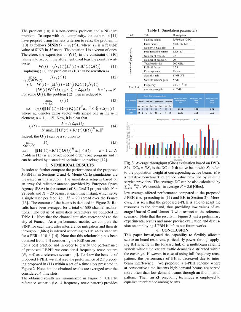
5. NUMERICAL RESULTSIn order to further compare the performance of the proposedJ-PBH in in Sections 2 and 4, Monte Carlo simulations arepresented in this section. The simulation setup is based onan array fed reflector antenna provided by European SpaceAgency (ESA) in the context of SatNexIII project with N =22 feeds and K = 20 beams, at each time instant, which servea single user per feed, i.e. M = 20 spread over the France[13]. The contour of the beams is depicted in Figure 2. Re-sults have been averaged for a total of 500 channel realiza-tions. The detail of simulation parameters are collected inTable 1. Note that the channel statistics corresponds to thecity of France. As a performance metric, we compute theSINR for each user, after interference mitigation and then itsthroughput (bit/s) is inferred according to DVB-S2x standardfor a PER of 10−6 [14]. Note that this relationship has beenobtained from [14] considering the PER curves.For a best practice and in order to clarify the performanceof proposed J-BPH, we consider 4 frequency reuse pattern(Nc = 4) as a reference scenario [4]. To show the benefits ofproposed J-PBH, we analysed the performance of ZF precod-ing proposed in (11) within a set of 4 time slots presented inFigure 2. Note that the obtained results are averaged over theconsidered 4 time slots.The obtained results are summarized in Figure 3. Clearly,reference scenario (i.e. 4 frequency reuse pattern) provides
Table 1. Simulation parametersLink Title Description
Forward
linkparam
eters
Satellite height 35786 km (GEO)
Earth radius 6378.137 KmNumer Of Satellites 1Feed radiation pattern ESA [13]
Number of feeds N 22Number of beams K 20Total bandwidth 500 MHzRoll-off factor 0.25Coverage area France
clear sky gain 17.68 G/T
Satellite antenna gain 57 dBi
User linkFrequency 20 × 109Hz
user antenna gain 41.7 dBi
Nº of Configuration
Number of total active and passive beams
Average offered capacity
considering DVB-S2x
[Gb/s]
Average unused system
capacity
[Gb/s]
Average unmet capacity
demand
[Gb/s]Time slot 1 Time slot 2 Time slot 3 Time slot 4
Fig. 3. Average throughput (Gb/s) evaluation based on DVB-S2x. DCk = RSk is the DC at k-th active beam with Sk refersto the population weight at corresponding active beam. R isa tentative benchmark reference value provided by satelliteservice providers. The Average DC can be also calculated by∑N
k=1RSkN
. We consider in average R = 2.6 [Gb/s].
low average offered performance compared to the proposedJ-PBH (i.e. precoding in (11) and BH in Section 2). More-over, it is seen that the proposed J-PBH is able to adapt theresources to the demand, thus providing low values of av-erage Unused-C and Unmet-D with respect to the referencescenario. Note that the results in Figure 3 just a preliminaryexperimental results and more precise evaluation and discus-sion on employing J-PBH is left to our future works.
6. CONCLUSIONThis paper investigated the capability to flexibly allocatescarce on-board resources, particularly power, through apply-ing BH scheme in the forward link of a multibeam satellitesystem while time variant traffic demands distributed withinthe coverage. However, in case of using full frequency reusepattern, the performance of BH is decreased due to inter-beam interference. We proposed a J-PBH scheme whereat consecutive time instants high-demand beams are servedmore often than low-demand beams through an illuminationpattern. Then, an ZF precoding technique is employed toequalize interference among beams.
References[1] Daniel Minoli, ”Innovations in satellite communications
technology,” in John Wiley & Sons Inc. Hoboken, USA,2015.
[2] D. Christopoulos, S. Chatzinotas, G. Zheng, J. Grotz,and B. Ottersten, ”Linear and nonlinear techniques formultibeam joint processing in satellite communications,”in Journal on Wireless Communications and Network-ing, vol. 2012, no. 1, p. 162, 2012.
[3] V. Joroughi, M. A. Vazquez, A. Ana Perez-Neira andB. Devillers, ”Design of an on board beam generationprocess for a multibeam broadband satellite system,” inIEEE Transactions on Wireless Communications, Vol.13, pp. 1-14, March 2017.
[4] V. Joroughi, M. A. Vzquez and A. I. Prez-Neira, ”Pre-coding in multigateway multibeam satellite systems,” inIEEE Transactions on Wireless Communications, Vol.15, No. 7, pp. 1-13, July 2016.
[5] E. Lagunas, S. Chatzinotas, V. Joroughi, and S. An-drenacci, ”Method for controlling the transmission ofsignals of a multibeam broadband satellite,” in Filed inLuxembourg Patent Office ref. LU100757, Apr. 2018.
[6] A. Freedman, D. Rainish, and Y. Gat, ”Beam hoppinghow to make it possible,” in Ka and Broadband Commu-nication Conference, Bologna, Italy, October 2015.
[7] ”NASA, Socioeconomic Data and Appli-cations Center (SEDAC),” Available at:http://sedac.ciesin.columbia.edu.
[8] C. R. Rao and S. K. Mitra,”Generalized inverse ofmatrices and its applications,” in John Wiley and sons,1971.
[9] A. Ginesi, E. Re, P.-D. Arapoglou, ”Joint beam hoppingand precoding in HTS systems,” in 9th EAI InternationalConference on Wireless and Satellite Systems (WISATS),Oxford, UK, September 2017.
[10] M.Kaliski, ”Evaluation of the next steps in satellitehigh power amplifier technology: Flexible TWTAs andGaN SSPAs” in IEEE International Vacuum Electronics
Conference, Italy, 2009.
[11] A. Wiesel, Y. C. Eldar and S. Shamai (Shitz) ”Zero-Forcing precoding and generalized inverses,” in IEEETransactions on Signal Processing, September 2008,Haifa, Israel.
[12] J. Lofberg, ”YALMIP A toolbox for modeling andoptimization in MATLAB,” in Proceedings of theCACSD Conference, Taiwan, 2004, Available fromhttp://control.ee.ethz.ch/joloef/yalmip.php.
[13] Call of Order 2-Task 1, ”Fair comparison and combi-nation of advanced interference mitigation techniques,”Satellite Network of Experts (SatNEx) 3, report of ESAcontract NO:23089/10/NL/CPL.
[14] ETSI EN 302 307-2: ”Digital Video Broadcasting(DVB);Second generation framing structure, channelcoding and modulation systems for Broadcasting, In-teractive Services,News Gathering and other broadbandsatellite applications;Part 2: DVB-S2 Extensions (DVB-S2X)”.