38
Deploying Network Address Translation within a Converged Plantwide Ethernet Architecture Design and Implementation Guide April 2016 Document Reference Number: ENET-TD007B-EN-P
Deploying Network Address Translation within a Converged Plantwide Ethernet Architecture
Design and Implementation Guide
April 2016
Document Reference Number: ENET-TD007B-EN-P
Preface
This Converged Plantwide Ethernet (CPwE) Network Address Translation (NAT) Cisco Validated Design (CVD) outlines the following key requirements and design considerations to help in the successful design and deployment of Industrial Automation and Control System (IACS) NAT networking within plant-wide architectures:
• CPwE NAT IACS Use Case Overview
• Review of NAT Technology:
– Layer 2 Industrial Ethernet Switch (IES)—Allen-Bradley® Stratix 5700™ and Cisco IE 2000
• Important Steps and Considerations for NAT Implementation and Configuration Recommendations with IACS Applications
• Maintaining and Troubleshooting the CPwE NAT
• CPwE NAT Test Results
Note CPwE focuses on EtherNet/IP™, which is driven by the ODVA Common Industrial Protocol (CIP). Refer to the IACS Communication Protocols section of the CPwE Design and Implementation Guide.
Document OrganizationThe CPwE NAT Design and Implementation Guide contains the following chapters:
Chapter Description
CPwE NAT Architecture Overview Introduction to the CPwE NAT Architecture, overview of CPwE NAT and CPwE NAT IACS use cases.
System Design Considerations Describes system design considerations when applying NAT for IACS applications.
Configuring the Infrastructure Provides an overview of key concepts and general configuration information as they pertain to the IE 2000/Stratix 5700 in various architectures.
Testing the Architecture Includes test objectives, setup, cases and topologies, and results.
iDeploying Network Address Translation (NAT) within a Converged Plantwide Ethernet Architecture CVD
ENET-TD007B-EN-P

PrefaceFor More Information
For More InformationRockwell Automation site:
• http://literature.rockwellautomation.com/idc/groups/literature/documents/td/enet-td001_-en-p.pdf
Cisco site:
• http://www.cisco.com/en/US/docs/solutions/Verticals/CPwE/CPwE_DIG.html
iiDeploying Network Address Translation (NAT) within a Converged Plantwide Ethernet Architecture CVD
ENET-TD007B-EN-P
Deploying Network Address Translation (NAT) within a Converge
ENET-TD007B-EN-P
C H A P T E R 1
CPwE NAT Architecture OverviewThis chapter includes the following major topics:
• CPwE NAT Architecture Introduction, page 1-1
• CPwE NAT Overview, page 1-2
• CPwE NAT IACS Use Cases, page 1-2
CPwE NAT Architecture IntroductionWhether you are an end user, OEM or system integrator, Internet Protocol (IP) addresses within your Industrial Automation and Control System (IACS) application may need to be reused. Network Address Translation (NAT) enables the reuse of IP addressing without introducing a duplicate IP address error into your IACS application architecture.
Technology and business aspects drive the decision to use NAT:
• From a business perspective, OEMs use NAT to enable the replication of skids and machines, including IP addressing. NAT can help reduce development and commissioning costs.
• From a technology perspective, end users use NAT when the IP address space within the plant-wide network infrastructure is limited and not every device requires communication outside the skid or machine-level network.
A strategic alliance between Cisco Systems® and Rockwell Automation brings Converged Plantwide Ethernet (CPwE) NAT for IACS applications to market. The CPwE NAT details scalable architectures to help with the successful design and implementation of NAT that meets the performance requirements of IACS applications.
CPwE is the underlying architecture that provides standard network services for control and information disciplines, devices and equipment found in modern IACS applications. The CPwE architecture provides design and implementation guidance to achieve the real-time communication, reliability, scalability and resiliency requirements of the IACS.
1-1d Plantwide Ethernet Architecture CVD
Chapter 1 CPwE NAT Architecture OverviewCPwE NAT Overview
CPwE NAT OverviewNAT is a networking technology that enables control system engineers to build IACS applications reusing IP (IPv4) addresses, while allowing those IACS applications to integrate into the larger plant-wide architecture. This requires unique IP addressing. NAT can be configured to translate only specific IP addresses from inside the IACS application to the outside plant-wide architecture. Doing so provides an added benefit of effectively hiding the inside IP addressing schema of the IACS application.
NAT translations have two forms: one-to-one (1:1) and one-to-many (1: n). The CPwE NAT tested and validated use cases use one-to-one NAT, implemented in a Layer 2 access switch. This unique implementation provides wire speed performance and supports multiple VLANs through the NAT boundary for enhanced network segmentation.
CPwE NAT IACS Use CasesThe CPwE NAT architecture is tailored to address a scalable application of NAT within the Cell/Area Zone of the CPwE architecture. Several NAT use cases have been individually tested and validated, allowing architectural selection that is practical to a small (machine/skid) or large-scale (Cell/Area Zone) plant-wide deployment.
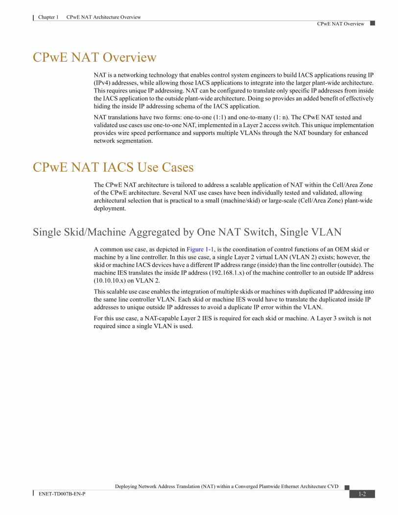
Single Skid/Machine Aggregated by One NAT Switch, Single VLAN
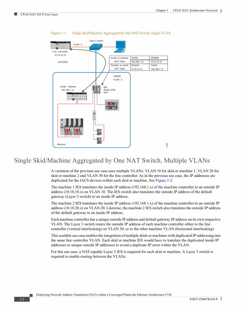
A common use case, as depicted in Figure 1-1, is the coordination of control functions of an OEM skid or machine by a line controller. In this use case, a single Layer 2 virtual LAN (VLAN 2) exists; however, the skid or machine IACS devices have a different IP address range (inside) than the line controller (outside). The machine IES translates the inside IP address (192.168.1.x) of the machine controller to an outside IP address (10.10.10.x) on VLAN 2.
This scalable use case enables the integration of multiple skids or machines with duplicated IP addressing into the same line controller VLAN. Each skid or machine IES would have to translate the duplicated inside IP addresses to unique outside IP addresses to avoid a duplicate IP error within the VLAN.
For this use case, a NAT-capable Layer 2 IES is required for each skid or machine. A Layer 3 switch is not required since a single VLAN is used.
1-2Deploying Network Address Translation (NAT) within a Converged Plantwide Ethernet Architecture CVD
ENET-TD007B-EN-P
Chapter 1 CPwE NAT Architecture OverviewCPwE NAT IACS Use Cases
Figure 1-1 Single Skid/Machine Aggregated by One NAT Switch, Single VLAN
Single Skid/Machine Aggregated by One NAT Switch, Multiple VLANs
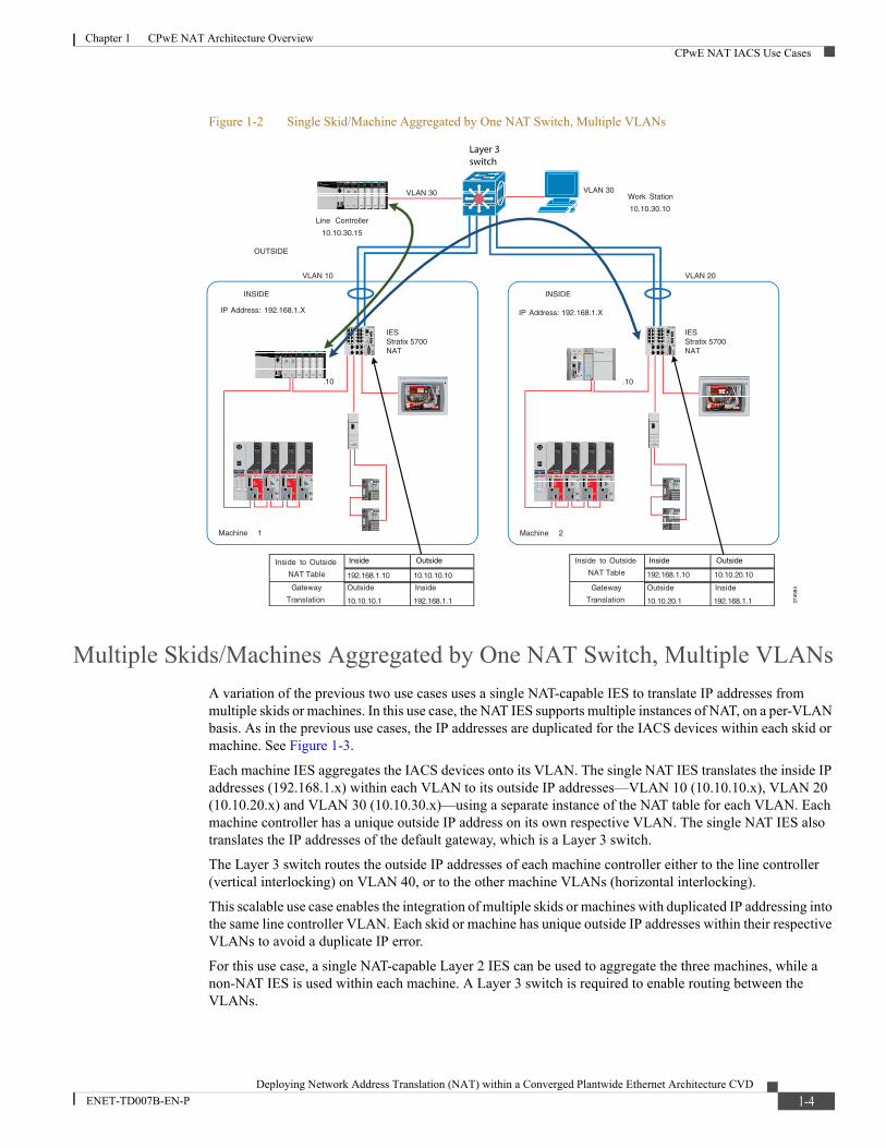
A variation of the previous use case uses multiple VLANs: VLAN 10 for skid or machine 1, VLAN 20 for skid or machine 2 and VLAN 30 for the line controller. As in the previous use case, the IP addresses are duplicated for the IACS devices within each skid or machine. See Figure 1-2.
The machine 1 IES translates the inside IP address (192.168.1.x) of the machine controller to an outside IP address (10.10.10.x) on VLAN 10. The IES switch also translates the outside IP address of the default gateway (Layer 3 switch) to an inside IP address.
The machine 2 IES translates the inside IP address (192.168.1.x) of the machine controller to an outside IP address (10.10.20.x) on VLAN 20. Likewise, the machine 2 IES switch also translates the outside IP address of the default gateway to an inside IP address.
Each machine controller has a unique outside IP address and default gateway IP address on its own respective VLAN. The Layer 3 switch routes the outside IP address of each machine controller either to the line controller (vertical interlocking) on VLAN 30, or to the other machine VLAN (horizontal interlocking).
This scalable use case enables the integration of multiple skids or machines with duplicated IP addressing into the same line controller VLAN. Each skid or machine IES would have to translate the duplicated inside IP addresses to unique outside IP addresses to avoid a duplicate IP error within the VLAN.
For this use case, a NAT-capable Layer 2 IES is required for each skid or machine. A Layer 3 switch is required to enable routing between the VLANs.
Machine
Inside Address
192.168.1.10
Layer 2 switch
VLAN 2
INSIDE
OUTSIDE
VLAN 2
Line Controller
10.10.10.15Inside to Outside
NAT Table
Outside to inside
NAT Table
3745
83
Inside Outside
IESStratix 5700NAT
1-3Deploying Network Address Translation (NAT) within a Converged Plantwide Ethernet Architecture CVD
ENET-TD007B-EN-P
Chapter 1 CPwE NAT Architecture OverviewCPwE NAT IACS Use Cases
Figure 1-2 Single Skid/Machine Aggregated by One NAT Switch, Multiple VLANs
Multiple Skids/Machines Aggregated by One NAT Switch, Multiple VLANs
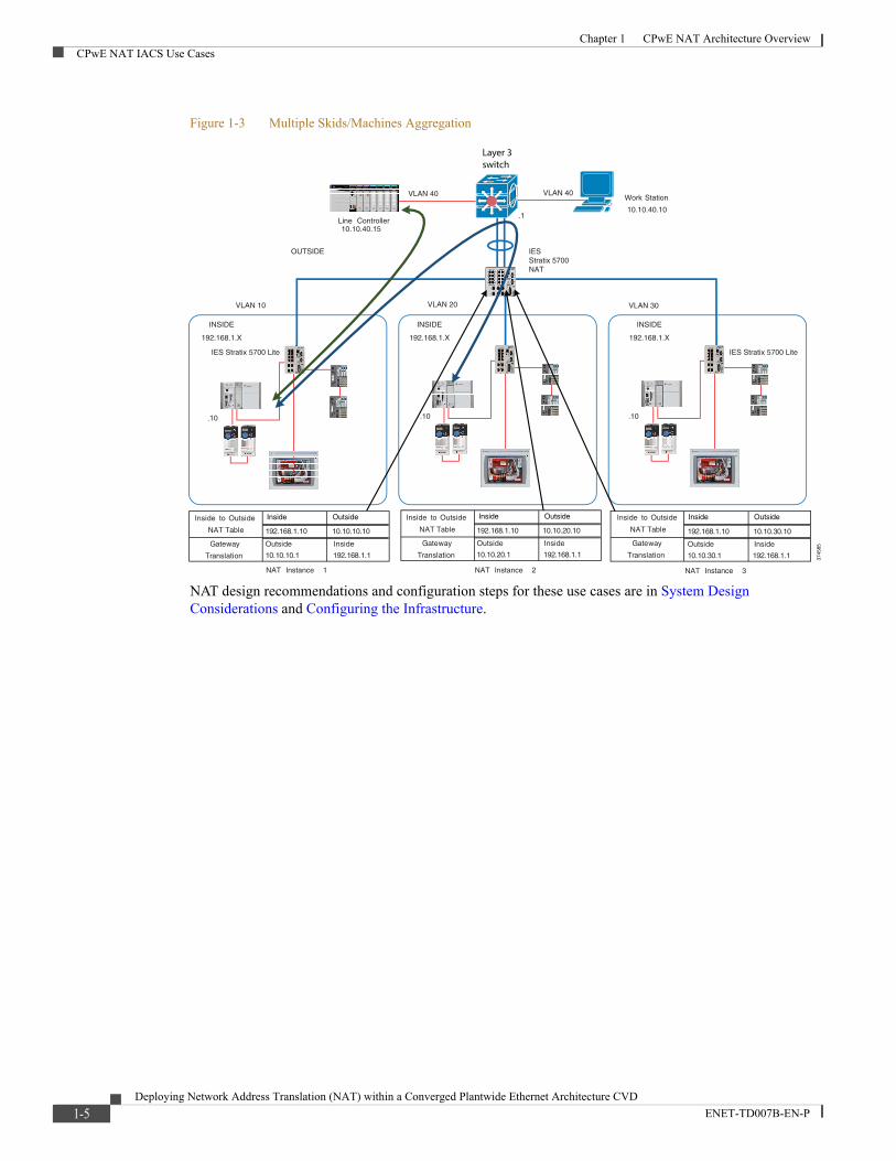
A variation of the previous two use cases uses a single NAT-capable IES to translate IP addresses from multiple skids or machines. In this use case, the NAT IES supports multiple instances of NAT, on a per-VLAN basis. As in the previous use cases, the IP addresses are duplicated for the IACS devices within each skid or machine. See Figure 1-3.
Each machine IES aggregates the IACS devices onto its VLAN. The single NAT IES translates the inside IP addresses (192.168.1.x) within each VLAN to its outside IP addresses—VLAN 10 (10.10.10.x), VLAN 20 (10.10.20.x) and VLAN 30 (10.10.30.x)—using a separate instance of the NAT table for each VLAN. Each machine controller has a unique outside IP address on its own respective VLAN. The single NAT IES also translates the IP addresses of the default gateway, which is a Layer 3 switch.
The Layer 3 switch routes the outside IP addresses of each machine controller either to the line controller (vertical interlocking) on VLAN 40, or to the other machine VLANs (horizontal interlocking).
This scalable use case enables the integration of multiple skids or machines with duplicated IP addressing into the same line controller VLAN. Each skid or machine has unique outside IP addresses within their respective VLANs to avoid a duplicate IP error.
For this use case, a single NAT-capable Layer 2 IES can be used to aggregate the three machines, while a non-NAT IES is used within each machine. A Layer 3 switch is required to enable routing between the VLANs.
Machine 1
.10
Work Station
10.10.30.10
VLAN 10 VLAN 20
VLAN 30
INSIDE
OUTSIDE
Machine 2
.10
VLAN 30
IP Address: 192.168.1.X IP Address: 192.168.1.X
INSIDE
Line Controller
10.10.30.15
Inside to Outside
NAT Table
Gateway
Translation
Inside to Outside
NAT Table
Gateway
Translation 3745
84
Inside Outside Inside Outside
Layer 3switch
IESStratix 5700NAT
IESStratix 5700NAT
1-4Deploying Network Address Translation (NAT) within a Converged Plantwide Ethernet Architecture CVD
ENET-TD007B-EN-P
Chapter 1 CPwE NAT Architecture OverviewCPwE NAT IACS Use Cases
Figure 1-3 Multiple Skids/Machines Aggregation
NAT design recommendations and configuration steps for these use cases are in System Design Considerations and Configuring the Infrastructure.
.10.101
1 1.10
Work Station
10.10.40.10
VLAN 40
VLAN 10 VLAN 20 VLAN 30
VLAN 40
Line Controller10.10.40.15
INSIDE
192.168.1.X
INSIDE
192.168.1.X
INSIDE
192.168.1.X
OUTSIDE
Inside to Outside
NAT Table
Gateway
Translation
Inside to Outside
NAT Table
Gateway
Translation
Inside to Outside
NAT Table
Gateway
Translation
NAT Instance 1 NAT Instance 2 NAT Instance 3
.1
3745
85
Inside Outside Inside Outside Inside Outside
Layer 3switch
IESStratix 5700NAT
IES Stratix 5700 Lite IES Stratix 5700 Lite
1-5Deploying Network Address Translation (NAT) within a Converged Plantwide Ethernet Architecture CVD
ENET-TD007B-EN-P
Deploying Network Address Translation (NAT) within a Converge
ENET-TD007B-EN-P
C H A P T E R 2
System Design ConsiderationsThis chapter, which describes system design considerations when applying NAT for IACS applications, includes the following major topics:
• NAT Technology Overview, page 2-1
• NAT Design Considerations, page 2-5
NAT Technology OverviewThis section provides an overview of NAT technology, including NAT types, operations and devices.
Types of NAT
NAT translations have two forms: One to One (1:1) and One to Many (1: n).
• One-to-One (1:1) NAT—A service that assigns a unique outside IP address to an inside device with an existing inside IP address. The device can then communicate on both the inside and outside subnets. This service is configured within a NAT-enabled device and is the outside translation of the IP address physically programmed on the inside device. NAT translations are typically entered into a table in the NAT-enabled device.
• One-to-Many (1:n) NAT—Also known as TCP/UDP Port Address Translation (PAT), is a service that allows multiple devices on the inside network to share one IP address on the outside network. TCP/UDP ports are translated in addition to the IP address to facilitate this service. The most common use of One-to-Many NAT is to connect users to Internet. The ISP's router is typically NAT-enabled and allows all individual private devices to access the Internet via the same single public address.
The 1:1 form of NAT can be implemented on a Layer 2 IES such as Cisco IE2000 or Allen-Bradley-Stratix 5700, or on a Layer 3 device (router). 1:n NAT is always implemented on a Layer 3 router. The differences between NAT implementations are described in more detail later in the document.
Note The products and architectures that are described in this document use the One-to-One (1:1) form of NAT.
2-1d Plantwide Ethernet Architecture CVD
Chapter 2 System Design ConsiderationsNAT Technology Overview
Note NAT devices may use words such as public to identify larger (that is, plant-wide) networks with a unique IP addressing scheme, and private to describe smaller (that is, machine-level) networks with reusable IP addresses. These terms should not be confused with the terms public and private when describing IP addresses routable on the Internet versus IP addresses reserved to be used in the local network (such as 192.168.x.x, 10.x.x.x, 172.16.x.x).
NAT Operation
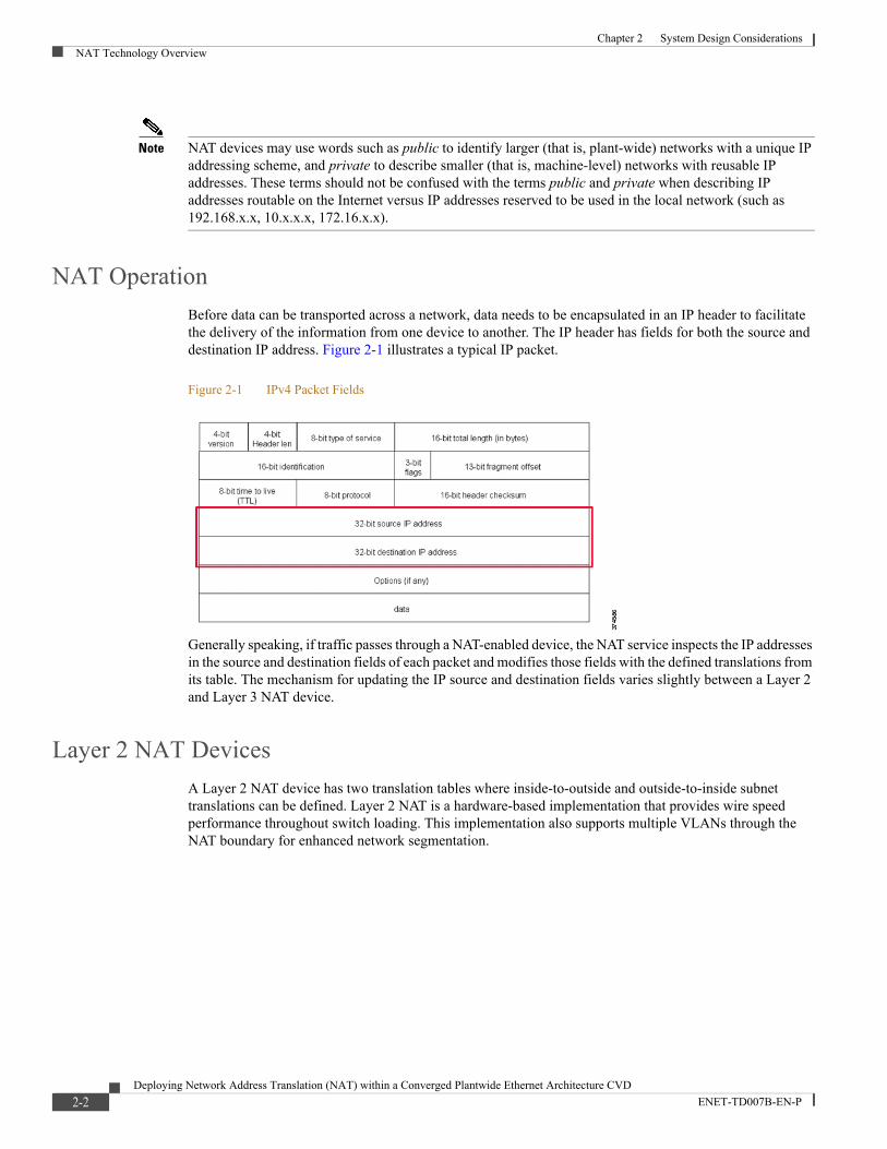
Before data can be transported across a network, data needs to be encapsulated in an IP header to facilitate the delivery of the information from one device to another. The IP header has fields for both the source and destination IP address. Figure 2-1 illustrates a typical IP packet.
Figure 2-1 IPv4 Packet Fields
Generally speaking, if traffic passes through a NAT-enabled device, the NAT service inspects the IP addresses in the source and destination fields of each packet and modifies those fields with the defined translations from its table. The mechanism for updating the IP source and destination fields varies slightly between a Layer 2 and Layer 3 NAT device.
Layer 2 NAT Devices
A Layer 2 NAT device has two translation tables where inside-to-outside and outside-to-inside subnet translations can be defined. Layer 2 NAT is a hardware-based implementation that provides wire speed performance throughout switch loading. This implementation also supports multiple VLANs through the NAT boundary for enhanced network segmentation.
2-2Deploying Network Address Translation (NAT) within a Converged Plantwide Ethernet Architecture CVD
ENET-TD007B-EN-P
Chapter 2 System Design ConsiderationsNAT Technology Overview
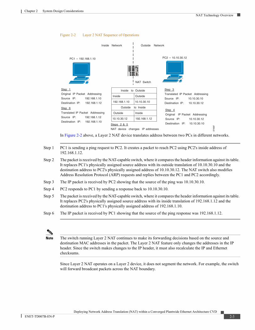
Figure 2-2 Layer 2 NAT Sequence of Operations
In Figure 2-2 above, a Layer 2 NAT device translates address between two PCs in different networks.
Step 1 PC1 is sending a ping request to PC2. It creates a packet to reach PC2 using PC2's inside address of 192.168.1.12.
Step 2 The packet is received by the NAT-capable switch, where it compares the header information against its table. It replaces PC1's physically assigned source address with its outside translation of 10.10.30.10 and the destination address to PC2's physically assigned address of 10.10.30.12. The NAT switch also modifies Address Resolution Protocol (ARP) requests and replies between the PC1 and PC2 accordingly.
Step 3 The IP packet is received by PC2 showing that the source of the ping was 10.10.30.10.
Step 4 PC2 responds to PC1 by sending a response back to 10.10.30.10.
Step 5 The packet is received by the NAT-capable switch, where it compares the header information against its table. It replaces PC2's physically assigned source address with its inside translation of 192.168.1.12 and the destination address to PC1's physically assigned address of 192.168.1.10.
Step 6 The IP packet is received by PC1 showing that the source of the ping response was 192.168.1.12.
Note The switch running Layer 2 NAT continues to make its forwarding decisions based on the source and destination MAC addresses in the packet. The Layer 2 NAT feature only changes the addresses in the IP header. Since the switch makes changes to the IP header, it must also recalculate the IP and Ethernet checksums.
Since Layer 2 NAT operates on a Layer 2 device, it does not segment the network. For example, the switch will forward broadcast packets across the NAT boundary.
Step 1
Original IP Packet Addressing
Source IP: 192.168.1.10
Destination IP: 192.168.1.12
PC1 – 192.168.1.10 PC2 – 10.10.30.12
Steps 2 & 5
NAT device changes IP addresses
Inside to Outside
Outside to Inside
Inside Outside
192.168.1.10 10.10.30.10
Outside Inside
10.10.30.12 192.168.1.12
NAT Switch
Inside Network Outside Network
Step 3
Translated IP Packet Addressing
Source IP: 10.10.30.10
Destination IP: 10.10.30.12
Step 4
Original IP Packet Addressing
Source IP: 10.10.30.12
Destination IP: 10.10.30.10
Step 6
Translated IP Packet Addressing
Source IP: 192.168.1.12
Destination IP: 192.168.1.10
3745
87
2-3Deploying Network Address Translation (NAT) within a Converged Plantwide Ethernet Architecture CVD
ENET-TD007B-EN-P
Chapter 2 System Design ConsiderationsNAT Technology Overview
Layer 3 NAT Devices
A Layer 3 NAT device has only one translation table for inside-to-outside translations and does not translate outside IP addresses back to inside IP addresses. Devices on the inside (private) network use a gateway address to communicate with the outside (public) network. Layer 3 NAT is typically a software-based implementation with performance with performance based on the CPU processing power and current loading.
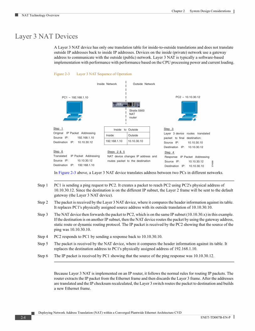
Figure 2-3 Layer 3 NAT Sequence of Operation
In Figure 2-3 above, a Layer 3 NAT device translates address between two PCs in different networks.
Step 1 PC1 is sending a ping request to PC2. It creates a packet to reach PC2 using PC2's physical address of 10.10.30.12. Since the destination is on the different IP subnet, the Layer 2 frame will be sent to the default gateway (the Layer 3 NAT device).
Step 2 The packet is received by the Layer 3 NAT device, where it compares the header information against its table. It replaces PC1's physically assigned source address with its outside translation of 10.10.30.10.
Step 3 The NAT device then forwards the packet to PC2, which is on the same IP subnet (10.10.30.x) in this example. If the destination is on another IP subnet, then the NAT device routes the packet by using the gateway address, static route or dynamic routing protocol. The IP packet is received by the PC2 showing that the source of the ping was 10.10.30.10.
Step 4 PC2 responds to PC1 by sending a response back to 10.10.30.10.
Step 5 The packet is received by the NAT device, where it compares the header information against its table. It replaces the destination address to PC1's physically assigned address of 192.168.1.10.
Step 6 The IP packet is received by PC1 showing that the source of the ping response was 10.10.30.12.
Because Layer 3 NAT is implemented on an IP router, it follows the normal rules for routing IP packets. The router extracts the IP packet from the Ethernet frame and then discards the Layer 3 frame. After the addresses are translated and the IP checksum recalculated, the Layer 3 switch routes the packet to destination and builds a new Ethernet frame.
Step 1
Original IP Packet Addressing
Source IP: 192.168.1.10
Destination IP: 10.10.30.12
PC1 – 192.168.1.10 PC2 – 10.10.30.12
Steps 2 & 5
NAT device changes IP address and
routes packet to the destination
Inside to Outside
Inside Outside
192.168.1.10 10.10.30.10
Inside Network Outside Network
Step 3
Layer 3 device routes translated
packet to final destination:
Source IP: 10.10.30.10
Destination IP: 10.10.30.12
Step 4
Response IP Packet Addressing
Source IP: 10.10.30.12
Destination IP: 10.10.30.10
Step 6
Translated IP Packet Addressing
Source IP: 10.10.30.12
Destination IP: 192.168.1.10 3745
88
Stratix 5900NATrouter
2-4Deploying Network Address Translation (NAT) within a Converged Plantwide Ethernet Architecture CVD
ENET-TD007B-EN-P
Chapter 2 System Design ConsiderationsNAT Design Considerations
Layer 2 and Layer 3 NAT Device Differences
As mentioned before, a Layer 3 NAT device acts as the default gateway (router) and can use static or dynamic routing to send traffic to the plant-wide network. A Layer 2 NAT device does not require a routing device unless communication between different VLANs / IP subnets is needed.
The following summarizes the key differentiators between a Layer 2 and Layer 3 NAT.
Layer 2 NAT Device Key Points
• Hardware-based implementation
• NAT device does not act as a router and uses 2 translation tables (Inside to Outside and Outside to Inside)
• Performance is at wire speed without impacting the CPU
• Multiple VLANs can be translated through NAT boundary using one or separate NAT instances (communication between VLANs requires a separate Layer 3 device)
• Broadcast traffic in a VLAN can propagate through the NAT boundary
• Untranslated traffic, including multicast, can be permitted through the NAT boundary
Layer 3 NAT Device Key Points
• Typically a software-based implementation
• NAT device acts as the default gateway (router) for the devices on the inside network
• NAT device will intercept traffic, perform translation, and route traffic
• Translations are handled by the NAT device CPU
• Performance of translation directly tied to the loading of the NAT device CPU
• Broadcast traffic is stopped at the NAT boundary
• Untranslated traffic is not permitted through the NAT device
Layer 2 NAT Implementation in IE 2000/Stratix 5700 Switch
The IE 2000/Stratix 5700 with NAT option is a hardware-based (Layer 2) 1:1 NAT implementation with wire speed performance. Multiple translation tables (NAT instances) can be created to easily integrate duplicate cells into an existing architecture. These tables are stored in the switch configuration and can be applied to one, or both uplinks for redundant paths.
The maximum number of translations per switch is 128. A NAT entry can be either a single IP address, a range of addresses or an entire subnet. A subnet translation is considered to be a single NAT entry.
The IE 2000/Stratix 5700 with NAT can be used in either a Layer 2 or Layer 3 network architecture. Multiple VLANs can be translated using one, or several NAT instances.
NAT functionality is only available on select IE 2000/Stratix 5700 catalog numbers.
NAT Design ConsiderationsThe first question that the end user, OEM or system integrator should consider is whether NAT is the right technology for the IACS application. NAT can bring advantages such as reduced commissioning cost, but can also add complexity to the plant-wide network design if not implemented correctly or implemented without real need.
2-5Deploying Network Address Translation (NAT) within a Converged Plantwide Ethernet Architecture CVD
ENET-TD007B-EN-P
Chapter 2 System Design ConsiderationsNAT Design Considerations
Some of the examples where NAT may NOT be a good solution are:
• Multiple skid or machine networks with significant variations in layout, design and control programs
• Multiple skids or machines with large number of translated addresses and large amount of interlocking traffic between areas
• NAT used as a segmentation method in a large network without implementing VLANs and Layer 3 hierarchical network design
It is important to consider the cost and difficulties of creating and managing NAT configuration. For example, a NAT switch may be part of the OEM machine, but it is typically an end user who is responsible for managing IP address translations across the plant.
If NAT is the right solution for the application, the next step is to choose the appropriate architecture. The following sections describe several architectures that cover the majority of the Layer 2 NAT use cases using IE2000/Stratix 5700 IES.
Single Skid/Machine Aggregated by One NAT Switch, Single VLAN
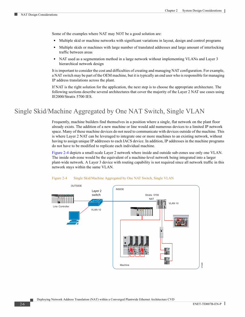
Frequently, machine builders find themselves in a position where a single, flat network on the plant floor already exists. The addition of a new machine or line would add numerous devices to a limited IP network space. Many of these machine devices do not need to communicate with devices outside of the machine. This is where Layer 2 NAT can be leveraged to integrate one or more machines to an existing network, without having to assign unique IP addresses to each IACS device. In addition, IP addresses in the machine programs do not have to be modified to replicate each individual machine.
Figure 2-4 depicts a small-scale Layer 2 network where inside and outside sub-zones use only one VLAN. The inside sub-zone would be the equivalent of a machine-level network being integrated into a larger plant-wide network. A Layer 3 device with routing capability is not required since all network traffic in this network stays within the same VLAN.
Figure 2-4 Single Skid/Machine Aggregated by One NAT Switch, Single VLAN
VLAN 10
INSIDEOUTSIDE
VLAN 10Line Controller
Stratix 5700
NAT
Machine
3745
89
Layer 2switch
2-6Deploying Network Address Translation (NAT) within a Converged Plantwide Ethernet Architecture CVD
ENET-TD007B-EN-P
Chapter 2 System Design ConsiderationsNAT Design Considerations
Since a router is not implemented in this architecture, a Layer 2 NAT solution is required, such as the IE 2000/Stratix 5700 IES. The Layer 2 NAT switch does not need a gateway address translation to communicate with the outside network; instead it makes use of an additional outside-to-inside table to perform the address translations.
Please note that each outside device that needs to communicate with the machine (such as PC or a line controller) must have an outside-to-inside translation in the NAT table.
It is important to understand that NAT on a Layer 2 switch in a flat (single VLAN) architecture does not fully segment the inside network from the outside network. Untranslated traffic (if permitted) and broadcast traffic can propagate across the NAT boundary. Multi-VLAN NAT architecture is necessary for full segmentation.
The total number of translated addresses in the Layer 2 network across all skids or machines should be limited to avoid issues such as excessive broadcast traffic or large Layer 2 fault domain. As the network grows, the Layer 2 architecture would have to be segmented. It is much easier to implement a fully segmented hierarchical design upfront than retroactively segment the network.
Single Skid/Machine Aggregated by One NAT Switch, Multiple VLANs
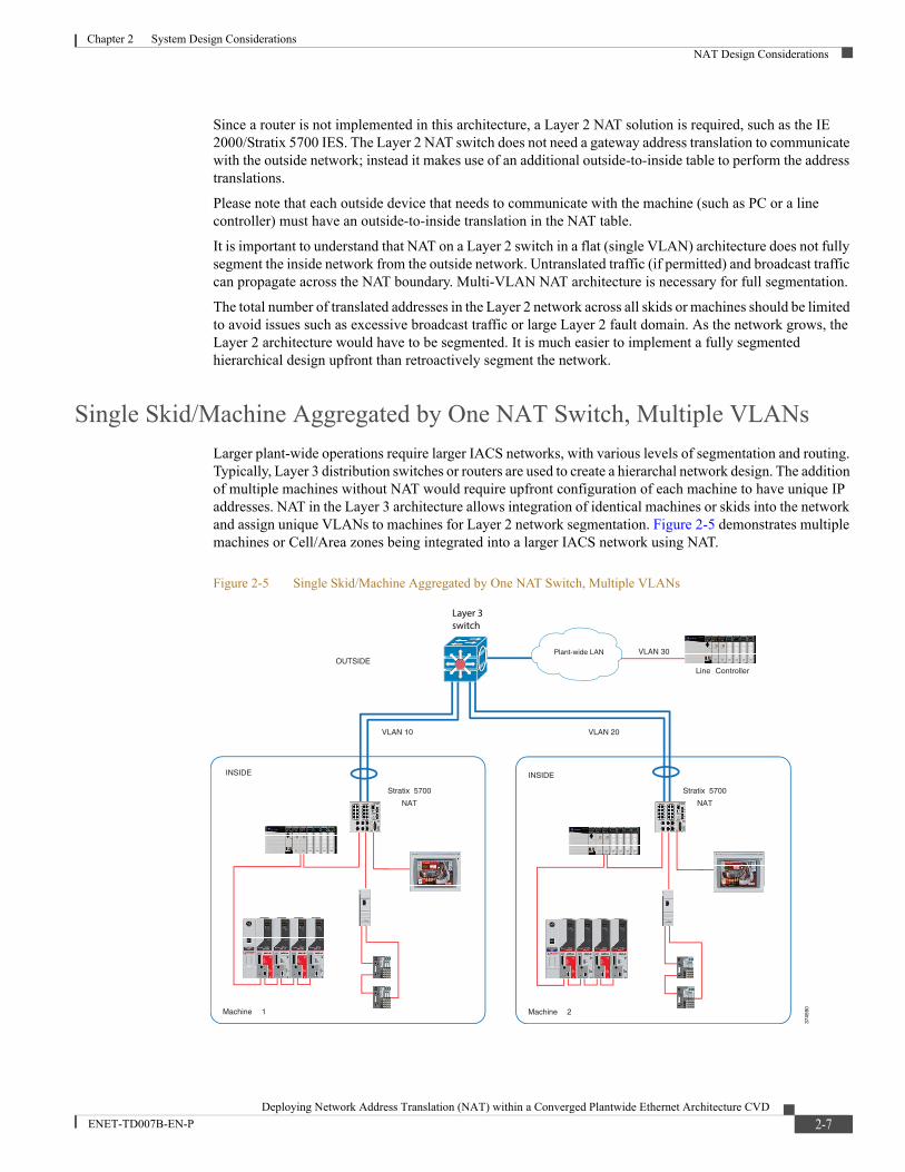
Larger plant-wide operations require larger IACS networks, with various levels of segmentation and routing. Typically, Layer 3 distribution switches or routers are used to create a hierarchal network design. The addition of multiple machines without NAT would require upfront configuration of each machine to have unique IP addresses. NAT in the Layer 3 architecture allows integration of identical machines or skids into the network and assign unique VLANs to machines for Layer 2 network segmentation. Figure 2-5 demonstrates multiple machines or Cell/Area zones being integrated into a larger IACS network using NAT.
Figure 2-5 Single Skid/Machine Aggregated by One NAT Switch, Multiple VLANs
Machine 1
Stratix 5700
NAT
VLAN 10 VLAN 20
INSIDE
OUTSIDE
Machine 2
VLAN 30
Line Controller
Stratix 5700
NAT
INSIDE
3745
90
Plant-wide LAN
Layer 3switch
2-7Deploying Network Address Translation (NAT) within a Converged Plantwide Ethernet Architecture CVD
ENET-TD007B-EN-P
Chapter 2 System Design ConsiderationsNAT Design Considerations
Each machine is the same, with IACS devices having the same IP addresses. Using a NAT IES in each machine enables machines to be connected to the plant-wide network without having to modify programs or device IP addresses. Not all devices have to be exposed to the plant-wide network, only those with a provided translation. This helps to limit the broadcast domain, hide machine devices from the rest of the plant-wide network (if desired), and helps enable more simplified, fast integration of the machines into the plant-wide network.
In the Layer 3 architecture shown above, the IE 2000/Stratix 5700 NAT table is configured with a gateway address translation instead of using an additional outside-to-inside translation table.
Redundant star topology is recommended for the architecture. Redundant links between the distribution switch and NAT IES can be configured with resilient protocols and methods such as Spanning Tree, EtherChannel or Flex Links.
Multiple Skids/Machines Aggregated by One NAT Switch, Multiple VLANs
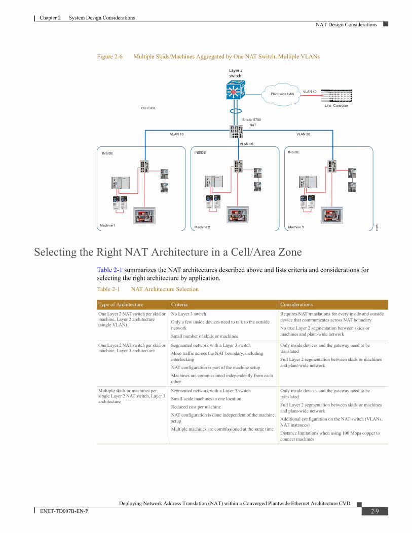
Depending on the application, it may not be necessary to have a NAT-enabled device within each skid or machine. To save on costs, it could make sense to use one IE 2000/Stratix 5700 with NAT, to connect multiple machines as shown in Figure 2-6. This configuration will only work with the IE 2000/Stratix 5700 NAT because it is the only IES that allows for multiple instances of NAT tables.
Instead of placing an IE 2000/Stratix 5700 with NAT in each machine, one is shared across multiple machines. To aggregate IACS devices within the machine, a lower cost option can be used such as a Stratix 5700 with the Lite software option.
Considerations when aggregating multiple inside networks on one NAT Layer 2 IES are listed below:
• Total number of translations is limited to 128 across all NAT instances.
• This architecture should be used for small-scale skids or machines with limited traffic across the NAT boundary.
• The NAT switch is a single point of failure for multiple skids or machines.
• IE 2000/Stratix 5700 with NAT has only 100 Mbps copper downlinks, which limits the distance.
2-8Deploying Network Address Translation (NAT) within a Converged Plantwide Ethernet Architecture CVD
ENET-TD007B-EN-P
Chapter 2 System Design ConsiderationsNAT Design Considerations
Figure 2-6 Multiple Skids/Machines Aggregated by One NAT Switch, Multiple VLANs
Selecting the Right NAT Architecture in a Cell/Area Zone
Table 2-1 summarizes the NAT architectures described above and lists criteria and considerations for selecting the right architecture by application.
11
Stratix 5700
NAT
1
OUTSIDE
VLAN 10
VLAN 20
VLAN 30
VLAN 40
Line Controller
INSIDE INSIDEINSIDE
3745
91
Plant-wide LAN
Layer 3switch
Machine 1 Machine 3Machine 2
Table 2-1 NAT Architecture Selection
Type of Architecture Criteria Considerations
One Layer 2 NAT switch per skid or machine, Layer 2 architecture (single VLAN)
No Layer 3 switch
Only a few inside devices need to talk to the outside network
Small number of skids or machines
Requires NAT translations for every inside and outside device that communicates across NAT boundary
No true Layer 2 segmentation between skids or machines and plant-wide network
One Layer 2 NAT switch per skid or machine, Layer 3 architecture
Segmented network with a Layer 3 switch
More traffic across the NAT boundary, including interlocking
NAT configuration is part of the machine setup
Machines are commissioned independently from each other
Only inside devices and the gateway need to be translated
Full Layer 2 segmentation between skids or machines and plant-wide network
Multiple skids or machines per single Layer 2 NAT switch, Layer 3 architecture
Segmented network with a Layer 3 switch
Small-scale machines in one location
Reduced cost per machine
NAT configuration is done independent of the machine setup
Multiple machines are commissioned at the same time
Only inside devices and the gateway need to be translated
Full Layer 2 segmentation between skids or machines and plant-wide network
Additional configuration on the NAT switch (VLANs, NAT instances)
Distance limitations when using 100 Mbps copper to connect machines
2-9Deploying Network Address Translation (NAT) within a Converged Plantwide Ethernet Architecture CVD
ENET-TD007B-EN-P
Chapter 2 System Design ConsiderationsNAT Design Considerations
NAT Limitations
Some types of traffic are not supported across the NAT boundary. Typically, for network protocols that use embedded IP addresses that are not fixed-up (changed by the NAT device in the application data), encrypted IP addresses or multicast IP are not supported across the boundary. However, this type of traffic is supported on either side of the NAT boundary.
These applications are not supported, which is typical for all NAT devices:
• Traffic encryption and integrity checking protocols generally incompatible with NAT (for example, IPsec transport mode)
• Applications that use dynamic session initiations, such as NetMeeting
• File Transfer Protocol (FTP)
• CIP Safety data to / from the Rockwell Automation® 1791-ES safety modules (IP address is in the safety signature and is not fixed-up, only applies to the Studio 5000® version 21 and later).
• Microsoft® Distributed Component Object Model (DCOM), which is used in Open Platform Communication (OPC)
• Multicast traffic, including applications that use multicast such as CIP Sync (IEEE1588) and ControlLogix redundancy
NAT and FactoryTalk Traffic
FactoryTalk® View Side Edition (SE) client/server communication may not operate correctly across a NAT boundary because it relies on protocols such as OPC and Domain Name System (DNS). Because of that, it is not recommended to have a distributed HMI network application with NAT between servers and clients. However, an HMI server on the outside network can access controller data from inside a NAT boundary and service clients in the outside network.
2-10Deploying Network Address Translation (NAT) within a Converged Plantwide Ethernet Architecture CVD
ENET-TD007B-EN-P
Deploying Network Address Translation (NAT) within a Converge
ENET-TD007B-EN-P
C H A P T E R 3
Configuring the InfrastructureSetting up NAT to work correctly on the IE 2000/Stratix 5700 varies with the network architecture in which it is being deployed. This chapter, which provides an overview of key concepts and general configuration information as they pertain to the IE 2000/Stratix 5700 in various architectures, includes the following major sections:
• IE 2000/Stratix 5700 NAT Implementation, page 3-1
• IE 2000/Stratix 5700 NAT Configuration, page 3-4
IE 2000/Stratix 5700 NAT ImplementationThis section describes the IE 2000/Stratix 5700 NAT implementation.
Hardware Implementation
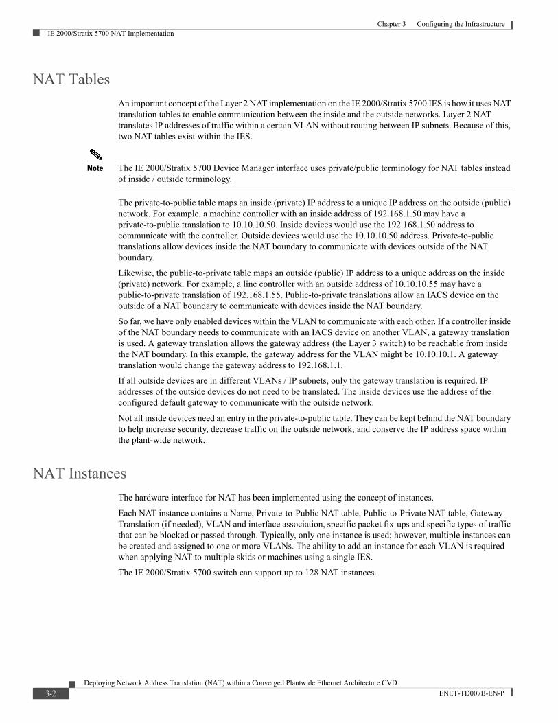
The IE 2000/Stratix 5700 incorporates 1:1 NAT in the IES hardware. It is a Layer 2 implementation that allows for wire speed translations. The translations only occur between the switch’s downlink (10/100 Mbps) and uplink (Gigabit) ports. Figure 3-1 illustrates that only traffic passing from the downlink to the uplinks or vice versa can be translated.
Figure 3-1 IE 2000/Stratix 5700 NAT Implementation
Uplink1Uplink1
(Optional)
Stratix 5700
NAT
Switch
Downlink Ports
3745
93
3-1d Plantwide Ethernet Architecture CVD
Chapter 3 Configuring the InfrastructureIE 2000/Stratix 5700 NAT Implementation
NAT Tables
An important concept of the Layer 2 NAT implementation on the IE 2000/Stratix 5700 IES is how it uses NAT translation tables to enable communication between the inside and the outside networks. Layer 2 NAT translates IP addresses of traffic within a certain VLAN without routing between IP subnets. Because of this, two NAT tables exist within the IES.
Note The IE 2000/Stratix 5700 Device Manager interface uses private/public terminology for NAT tables instead of inside / outside terminology.
The private-to-public table maps an inside (private) IP address to a unique IP address on the outside (public) network. For example, a machine controller with an inside address of 192.168.1.50 may have a private-to-public translation to 10.10.10.50. Inside devices would use the 192.168.1.50 address to communicate with the controller. Outside devices would use the 10.10.10.50 address. Private-to-public translations allow devices inside the NAT boundary to communicate with devices outside of the NAT boundary.
Likewise, the public-to-private table maps an outside (public) IP address to a unique address on the inside (private) network. For example, a line controller with an outside address of 10.10.10.55 may have a public-to-private translation of 192.168.1.55. Public-to-private translations allow an IACS device on the outside of a NAT boundary to communicate with devices inside the NAT boundary.
So far, we have only enabled devices within the VLAN to communicate with each other. If a controller inside of the NAT boundary needs to communicate with an IACS device on another VLAN, a gateway translation is used. A gateway translation allows the gateway address (the Layer 3 switch) to be reachable from inside the NAT boundary. In this example, the gateway address for the VLAN might be 10.10.10.1. A gateway translation would change the gateway address to 192.168.1.1.
If all outside devices are in different VLANs / IP subnets, only the gateway translation is required. IP addresses of the outside devices do not need to be translated. The inside devices use the address of the configured default gateway to communicate with the outside network.
Not all inside devices need an entry in the private-to-public table. They can be kept behind the NAT boundary to help increase security, decrease traffic on the outside network, and conserve the IP address space within the plant-wide network.
NAT Instances
The hardware interface for NAT has been implemented using the concept of instances.
Each NAT instance contains a Name, Private-to-Public NAT table, Public-to-Private NAT table, Gateway Translation (if needed), VLAN and interface association, specific packet fix-ups and specific types of traffic that can be blocked or passed through. Typically, only one instance is used; however, multiple instances can be created and assigned to one or more VLANs. The ability to add an instance for each VLAN is required when applying NAT to multiple skids or machines using a single IES.
The IE 2000/Stratix 5700 switch can support up to 128 NAT instances.
3-2Deploying Network Address Translation (NAT) within a Converged Plantwide Ethernet Architecture CVD
ENET-TD007B-EN-P
Chapter 3 Configuring the InfrastructureIE 2000/Stratix 5700 NAT Implementation
Types of Translations
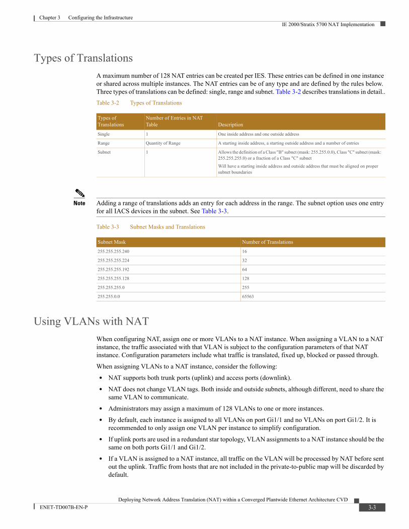
A maximum number of 128 NAT entries can be created per IES. These entries can be defined in one instance or shared across multiple instances. The NAT entries can be of any type and are defined by the rules below. Three types of translations can be defined: single, range and subnet. Table 3-2 describes translations in detail..
Note Adding a range of translations adds an entry for each address in the range. The subnet option uses one entry for all IACS devices in the subnet. See Table 3-3.
Using VLANs with NAT
When configuring NAT, assign one or more VLANs to a NAT instance. When assigning a VLAN to a NAT instance, the traffic associated with that VLAN is subject to the configuration parameters of that NAT instance. Configuration parameters include what traffic is translated, fixed up, blocked or passed through.
When assigning VLANs to a NAT instance, consider the following:
• NAT supports both trunk ports (uplink) and access ports (downlink).
• NAT does not change VLAN tags. Both inside and outside subnets, although different, need to share the same VLAN to communicate.
• Administrators may assign a maximum of 128 VLANs to one or more instances.
• By default, each instance is assigned to all VLANs on port Gi1/1 and no VLANs on port Gi1/2. It is recommended to only assign one VLAN per instance to simplify configuration.
• If uplink ports are used in a redundant star topology, VLAN assignments to a NAT instance should be the same on both ports Gi1/1 and Gi1/2.
• If a VLAN is assigned to a NAT instance, all traffic on the VLAN will be processed by NAT before sent out the uplink. Traffic from hosts that are not included in the private-to-public map will be discarded by default.
Table 3-2 Types of Translations
Types of Translations
Number of Entries in NAT Table Description
Single 1 One inside address and one outside address
Range Quantity of Range A starting inside address, a starting outside address and a number of entries
Subnet 1 Allows the definition of a Class "B" subnet (mask: 255.255.0.0), Class "C" subnet (mask: 255.255.255.0) or a fraction of a Class "C" subnet
Will have a starting inside address and outside address that must be aligned on proper subnet boundaries
Table 3-3 Subnet Masks and Translations
Subnet Mask Number of Translations
255.255.255.240 16
255.255.255.224 32
255.255.255.192 64
255.255.255.128 128
255.255.255.0 255
255.255.0.0 65563
3-3Deploying Network Address Translation (NAT) within a Converged Plantwide Ethernet Architecture CVD
ENET-TD007B-EN-P
Chapter 3 Configuring the InfrastructureIE 2000/Stratix 5700 NAT Configuration
• If a VLAN is not assigned to a NAT instance, its traffic remains untranslated and is always permitted to pass through the trunk port.
Switch Management Interface
The management interface can be associated with a VLAN that is or is not assigned to a NAT instance:
• If the management VLAN is assigned to a NAT instance, the management interface resides on the inside (private) subnet by default. To manage the switch from the inside network, additional configuration is not required. To manage the switch from the outside (public) subnet, configure a private-to-public translation for the management IP address.
• If the management VLAN is not assigned to a NAT instance, the switch management traffic remains untranslated and is always permitted to pass through the port
Allowed Traffic and Fix-Ups
The IE 2000/Stratix 5700 NAT implementation allows certain types of traffic to either pass or be blocked; this is referred to as traffic permits. The permits can be assigned on a per-instance basis. Traffic on VLANs not attached to an instance will be unaffected by these rules. The types of traffic that can either be blocked or passed-through on an incoming or outgoing basis are unicast, multicast and Internet Group Management Protocol (IGMP).
• Unicast traffic that is not translated can be passed through (with its original IP information) to the outside or inside network, or blocked.
• While multicast is not supported for NAT translation, it can be passed through or blocked by the user when necessary.
• IGMP can also be passed through or blocked.
• Broadcast traffic will flow seamlessly through the NAT boundary if a public-to-private translation exists for the sending device.
Certain types of traffic have IP addresses embedded within the packet and would need to be fixed-up to pass through the NAT boundary. Currently, only ARP and Internet Control Message Protocol (ICMP) traffic can be fixed up. This can be set on a per-instance basis. By default, these fix-ups are enabled.
IE 2000/Stratix 5700 NAT ConfigurationThis section includes configuration steps for Layer 2, Layer 3 and Aggregation of Multiple Machines using one NAT IES.
Single Skid/Machine Aggregated by One NAT Switch, Single VLAN
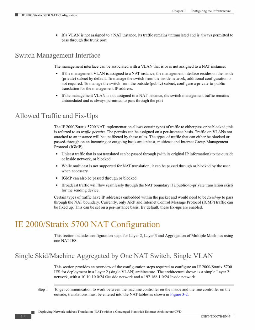
This section provides an overview of the configuration steps required to configure an IE 2000/Stratix 5700 IES for deployment in a Layer 2 (single VLAN) architecture. The architecture shown is a simple Layer 2 network, with a 10.10.10.0/24 Outside network and a 192.168.1.0/24 Inside network.
Step 1 To get communication to work between the machine controller on the inside and the line controller on the outside, translations must be entered into the NAT tables as shown in Figure 3-2.
3-4Deploying Network Address Translation (NAT) within a Converged Plantwide Ethernet Architecture CVD
ENET-TD007B-EN-P
Chapter 3 Configuring the InfrastructureIE 2000/Stratix 5700 NAT Configuration
Figure 3-2 Single Skid/Machine Aggregated by One NAT Switch, Single VLAN
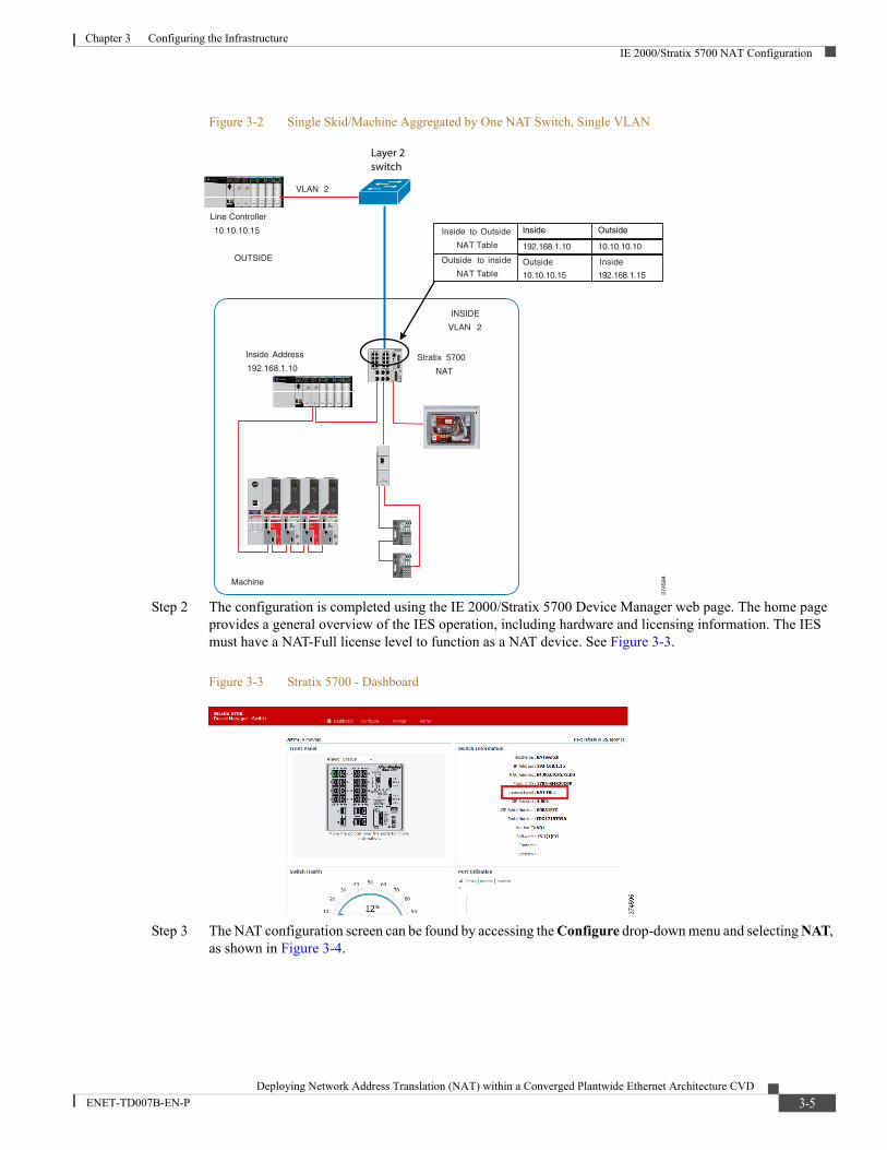
Step 2 The configuration is completed using the IE 2000/Stratix 5700 Device Manager web page. The home page provides a general overview of the IES operation, including hardware and licensing information. The IES must have a NAT-Full license level to function as a NAT device. See Figure 3-3.
Figure 3-3 Stratix 5700 - Dashboard
Step 3 The NAT configuration screen can be found by accessing the Configure drop-down menu and selecting NAT, as shown in Figure 3-4.
Machine
Inside Address
192.168.1.10
VLAN 2
INSIDE
OUTSIDE
VLAN 2
Line Controller
10.10.10.15
Stratix 5700
NAT
Inside to Outside
NAT Table
Outside to inside
NAT Table
3745
94
Inside Outside
Layer 2switch
3-5Deploying Network Address Translation (NAT) within a Converged Plantwide Ethernet Architecture CVD
ENET-TD007B-EN-P
Chapter 3 Configuring the InfrastructureIE 2000/Stratix 5700 NAT Configuration
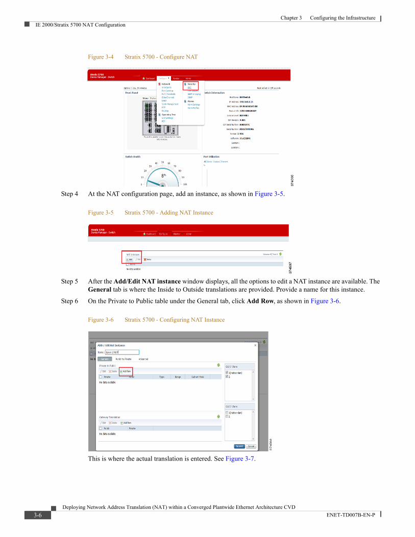
Figure 3-4 Stratix 5700 - Configure NAT
Step 4 At the NAT configuration page, add an instance, as shown in Figure 3-5.
Figure 3-5 Stratix 5700 - Adding NAT Instance
Step 5 After the Add/Edit NAT instance window displays, all the options to edit a NAT instance are available. The General tab is where the Inside to Outside translations are provided. Provide a name for this instance.
Step 6 On the Private to Public table under the General tab, click Add Row, as shown in Figure 3-6.
Figure 3-6 Stratix 5700 - Configuring NAT Instance
This is where the actual translation is entered. See Figure 3-7.
3-6Deploying Network Address Translation (NAT) within a Converged Plantwide Ethernet Architecture CVD
ENET-TD007B-EN-P
Chapter 3 Configuring the InfrastructureIE 2000/Stratix 5700 NAT Configuration
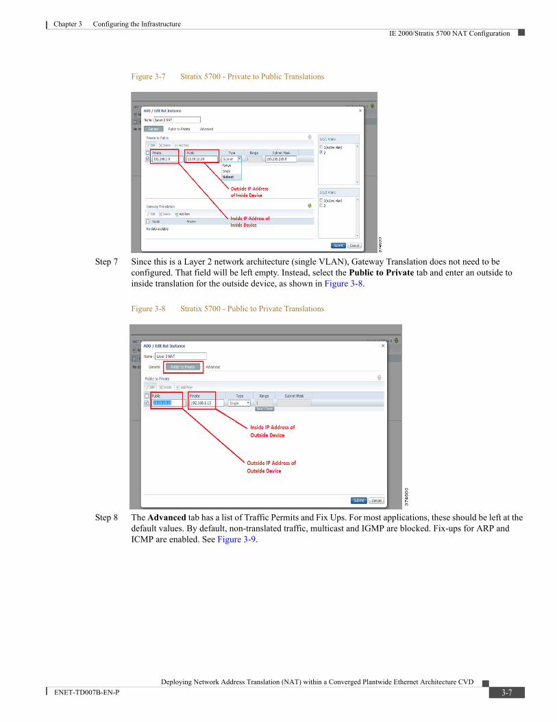
Figure 3-7 Stratix 5700 - Private to Public Translations
Step 7 Since this is a Layer 2 network architecture (single VLAN), Gateway Translation does not need to be configured. That field will be left empty. Instead, select the Public to Private tab and enter an outside to inside translation for the outside device, as shown in Figure 3-8.
Figure 3-8 Stratix 5700 - Public to Private Translations
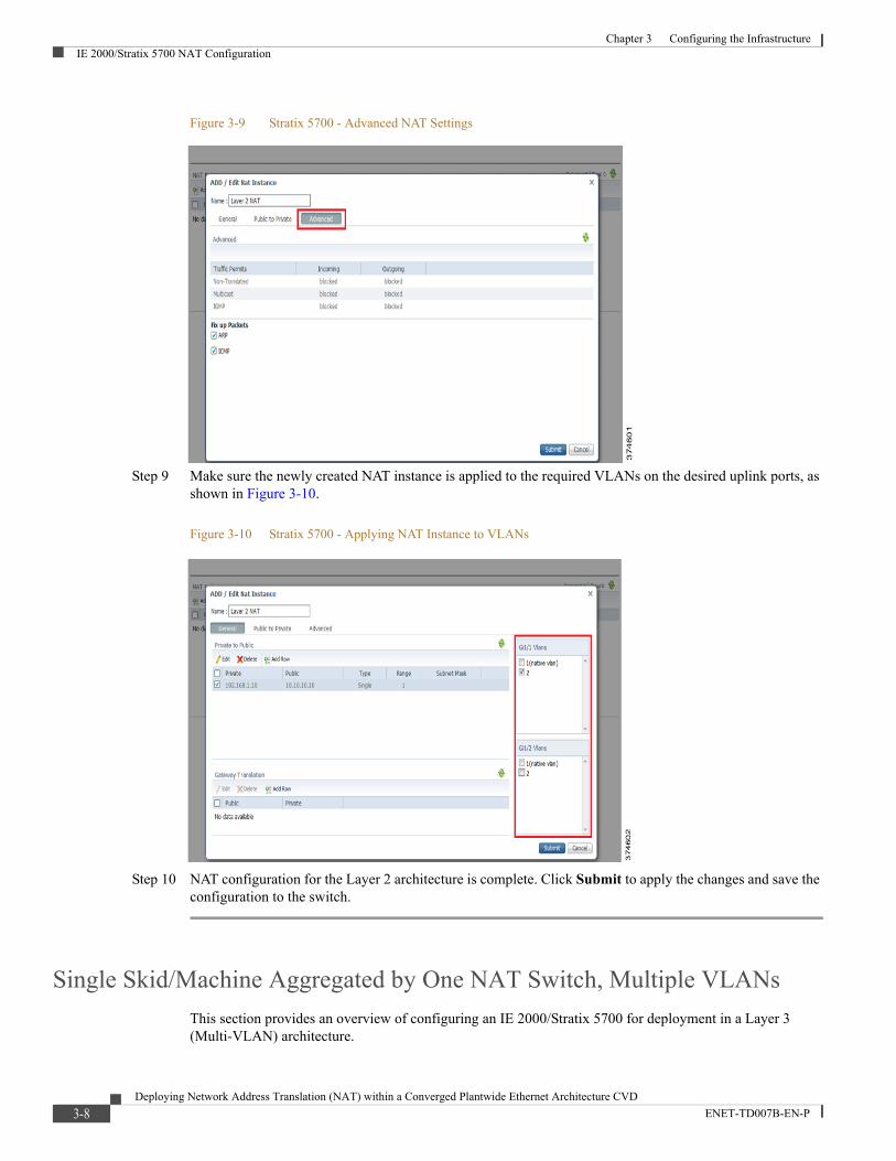
Step 8 The Advanced tab has a list of Traffic Permits and Fix Ups. For most applications, these should be left at the default values. By default, non-translated traffic, multicast and IGMP are blocked. Fix-ups for ARP and ICMP are enabled. See Figure 3-9.
3-7Deploying Network Address Translation (NAT) within a Converged Plantwide Ethernet Architecture CVD
ENET-TD007B-EN-P
Chapter 3 Configuring the InfrastructureIE 2000/Stratix 5700 NAT Configuration
Figure 3-9 Stratix 5700 - Advanced NAT Settings
Step 9 Make sure the newly created NAT instance is applied to the required VLANs on the desired uplink ports, as shown in Figure 3-10.
Figure 3-10 Stratix 5700 - Applying NAT Instance to VLANs
Step 10 NAT configuration for the Layer 2 architecture is complete. Click Submit to apply the changes and save the configuration to the switch.
Single Skid/Machine Aggregated by One NAT Switch, Multiple VLANs
This section provides an overview of configuring an IE 2000/Stratix 5700 for deployment in a Layer 3 (Multi-VLAN) architecture.
3-8Deploying Network Address Translation (NAT) within a Converged Plantwide Ethernet Architecture CVD
ENET-TD007B-EN-P
Chapter 3 Configuring the InfrastructureIE 2000/Stratix 5700 NAT Configuration
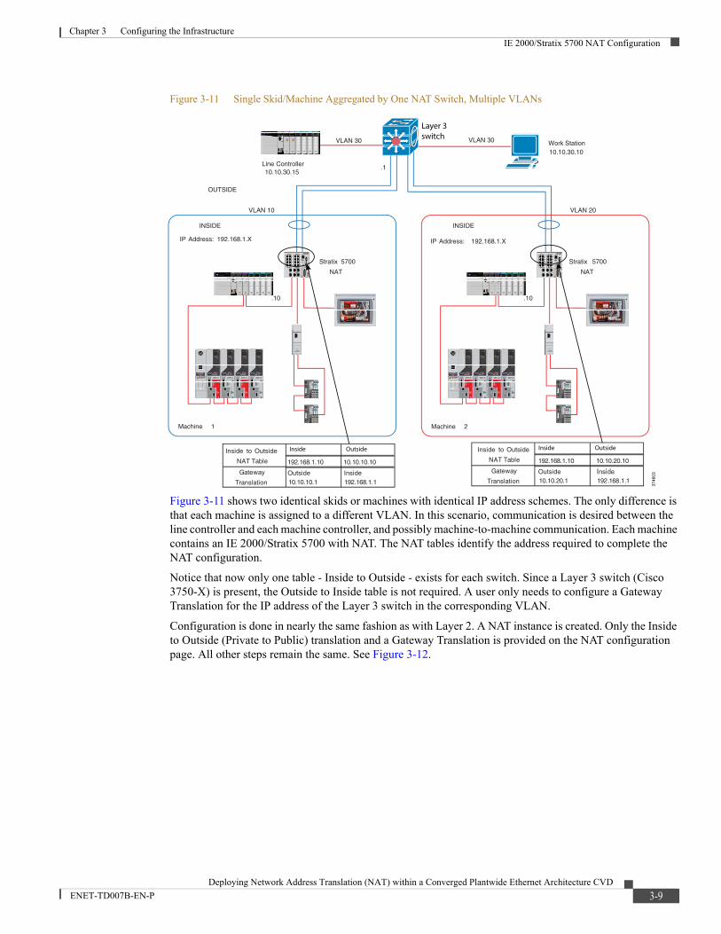
Figure 3-11 Single Skid/Machine Aggregated by One NAT Switch, Multiple VLANs
Figure 3-11 shows two identical skids or machines with identical IP address schemes. The only difference is that each machine is assigned to a different VLAN. In this scenario, communication is desired between the line controller and each machine controller, and possibly machine-to-machine communication. Each machine contains an IE 2000/Stratix 5700 with NAT. The NAT tables identify the address required to complete the NAT configuration.
Notice that now only one table - Inside to Outside - exists for each switch. Since a Layer 3 switch (Cisco 3750-X) is present, the Outside to Inside table is not required. A user only needs to configure a Gateway Translation for the IP address of the Layer 3 switch in the corresponding VLAN.
Configuration is done in nearly the same fashion as with Layer 2. A NAT instance is created. Only the Inside to Outside (Private to Public) translation and a Gateway Translation is provided on the NAT configuration page. All other steps remain the same. See Figure 3-12.
.10.10
Machine 1
Stratix 5700
NAT
Work Station10.10.30.10
VLAN 10 VLAN 20
VLAN 30
INSIDE
OUTSIDE
Machine 2
VLAN 30
IP Address: 192.168.1.X IP Address: 192.168.1.X
Stratix 5700
NAT
INSIDE
Line Controller10.10.30.15
Inside to Outside
NAT Table
Gateway
Translation
Inside to Outside
NAT Table
Gateway
Translation
.1
3746
03
Inside OutsideInside Outside
Layer 3switch
3-9Deploying Network Address Translation (NAT) within a Converged Plantwide Ethernet Architecture CVD
ENET-TD007B-EN-P
Chapter 3 Configuring the InfrastructureIE 2000/Stratix 5700 NAT Configuration
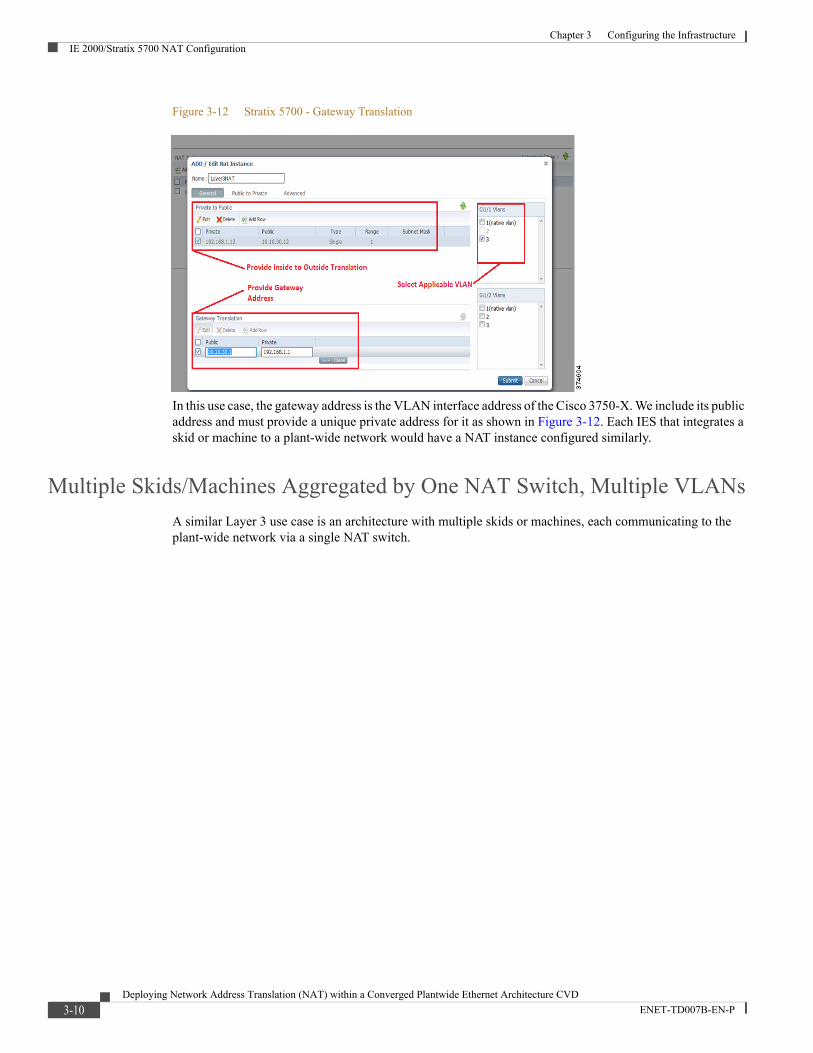
Figure 3-12 Stratix 5700 - Gateway Translation
In this use case, the gateway address is the VLAN interface address of the Cisco 3750-X. We include its public address and must provide a unique private address for it as shown in Figure 3-12. Each IES that integrates a skid or machine to a plant-wide network would have a NAT instance configured similarly.
Multiple Skids/Machines Aggregated by One NAT Switch, Multiple VLANs
A similar Layer 3 use case is an architecture with multiple skids or machines, each communicating to the plant-wide network via a single NAT switch.
3-10Deploying Network Address Translation (NAT) within a Converged Plantwide Ethernet Architecture CVD
ENET-TD007B-EN-P
Chapter 3 Configuring the InfrastructureIE 2000/Stratix 5700 NAT Configuration
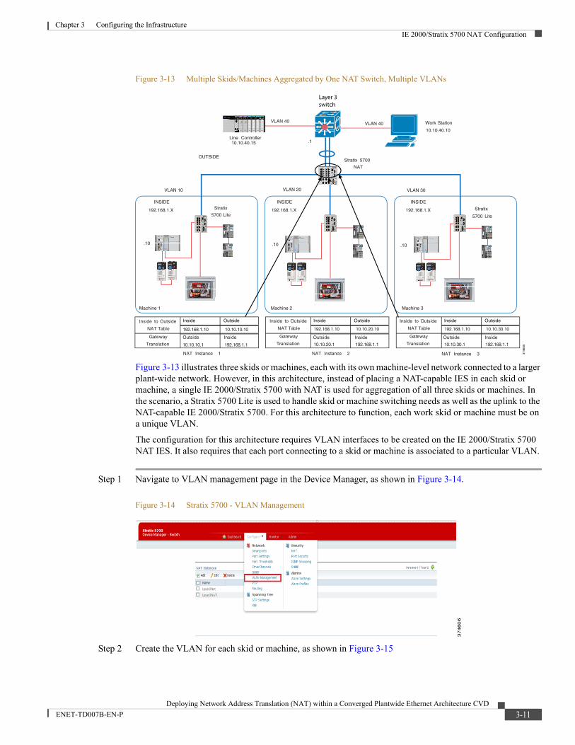
Figure 3-13 Multiple Skids/Machines Aggregated by One NAT Switch, Multiple VLANs
Figure 3-13 illustrates three skids or machines, each with its own machine-level network connected to a larger plant-wide network. However, in this architecture, instead of placing a NAT-capable IES in each skid or machine, a single IE 2000/Stratix 5700 with NAT is used for aggregation of all three skids or machines. In the scenario, a Stratix 5700 Lite is used to handle skid or machine switching needs as well as the uplink to the NAT-capable IE 2000/Stratix 5700. For this architecture to function, each work skid or machine must be on a unique VLAN.
The configuration for this architecture requires VLAN interfaces to be created on the IE 2000/Stratix 5700 NAT IES. It also requires that each port connecting to a skid or machine is associated to a particular VLAN.
Step 1 Navigate to VLAN management page in the Device Manager, as shown in Figure 3-14.
Figure 3-14 Stratix 5700 - VLAN Management
Step 2 Create the VLAN for each skid or machine, as shown in Figure 3-15
1
Stratix 5700
NAT
1 1
Work Station
10.10.40.10
VLAN 40
VLAN 10 VLAN 20 VLAN 30
VLAN 40
Line Controller10.10.40.15
INSIDE
192.168.1.X
INSIDE
192.168.1.X
INSIDE
192.168.1.X
OUTSIDE
Stratix
5700 Lite
Inside to Outside
NAT Table
Gateway
Translation
Inside to Outside
NAT Table
Gateway
Translation
Inside to Outside
NAT Table
Gateway
Translation
NAT Instance 1 NAT Instance 2 NAT Instance 3
.1
Stratix
5700 Lite
.10 .10 .10
3746
05
Inside Outside Inside Outside Inside Outside
Layer 3switch
Machine 1 Machine 2 Machine 3
3-11Deploying Network Address Translation (NAT) within a Converged Plantwide Ethernet Architecture CVD
ENET-TD007B-EN-P
Chapter 3 Configuring the InfrastructureIE 2000/Stratix 5700 NAT Configuration
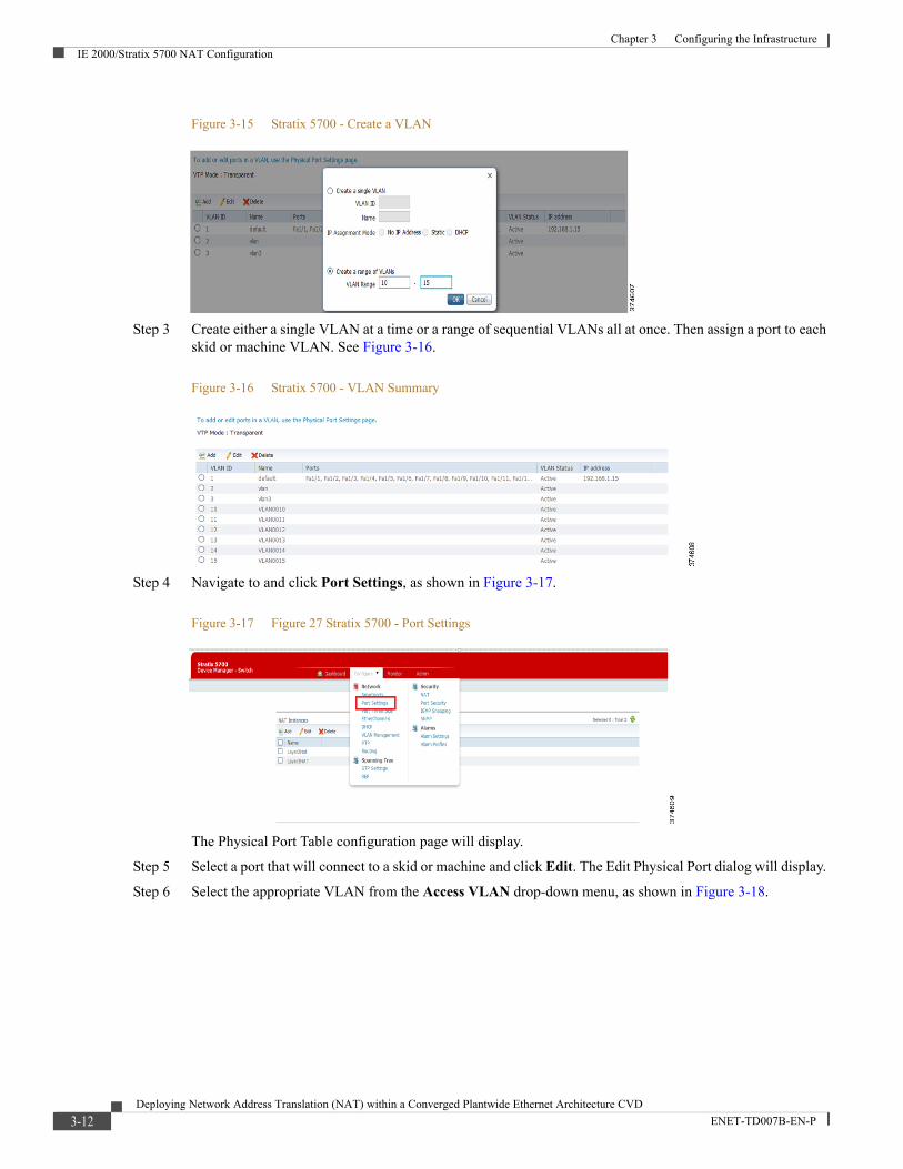
Figure 3-15 Stratix 5700 - Create a VLAN
Step 3 Create either a single VLAN at a time or a range of sequential VLANs all at once. Then assign a port to each skid or machine VLAN. See Figure 3-16.
Figure 3-16 Stratix 5700 - VLAN Summary
Step 4 Navigate to and click Port Settings, as shown in Figure 3-17.
Figure 3-17 Figure 27 Stratix 5700 - Port Settings
The Physical Port Table configuration page will display.
Step 5 Select a port that will connect to a skid or machine and click Edit. The Edit Physical Port dialog will display.
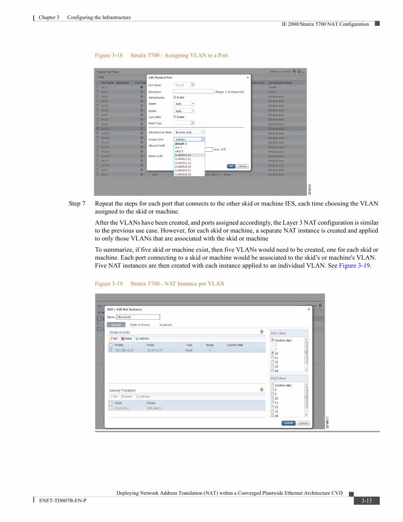
Step 6 Select the appropriate VLAN from the Access VLAN drop-down menu, as shown in Figure 3-18.
3-12Deploying Network Address Translation (NAT) within a Converged Plantwide Ethernet Architecture CVD
ENET-TD007B-EN-P
Chapter 3 Configuring the InfrastructureIE 2000/Stratix 5700 NAT Configuration
Figure 3-18 Stratix 5700 - Assigning VLAN to a Port
Step 7 Repeat the steps for each port that connects to the other skid or machine IES, each time choosing the VLAN assigned to the skid or machine.
After the VLANs have been created, and ports assigned accordingly, the Layer 3 NAT configuration is similar to the previous use case. However, for each skid or machine, a separate NAT instance is created and applied to only those VLANs that are associated with the skid or machine
To summarize, if five skid or machine exist, then five VLANs would need to be created, one for each skid or machine. Each port connecting to a skid or machine would be associated to the skid’s or machine's VLAN. Five NAT instances are then created with each instance applied to an individual VLAN. See Figure 3-19.
Figure 3-19 Stratix 5700 - NAT Instance per VLAN
3-13Deploying Network Address Translation (NAT) within a Converged Plantwide Ethernet Architecture CVD
ENET-TD007B-EN-P
Deploying Network Address Translation (NAT) within a Converge
ENET-TD007B-EN-P
C H A P T E R 4
Testing the ArchitectureThis chapter includes the following major topics:
• Test Objectives, page 4-1
• Test Setup, page 4-1
• Test Cases and Topologies, page 4-2
• Test Results, page 4-5
Test ObjectivesIn order to validate operation and test the performance of the Layer 2 NAT using the IE 2000/Stratix 5700 IES, each architecture presented as a use case was set up and IACS traffic applied. Latency data has been captured not just through the IES, but through the entire path from endpoint to endpoint. This gives a realistic value that is more representative of what users would experience in a typical deployment.
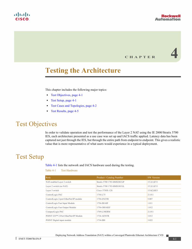
Test SetupTable 4-1 lists the network and IACS hardware used during the testing.
Table 4-1 Test Hardware
Role Product / Catalog Number SW Version
NAT-enabled Layer 2 switch Stratix 5700 1783-BMS20CGP 15.2(1)EY1
Layer 2 switch (no NAT) Stratix 5700 1783-BMS10CGL 15.2(1)EY1
Layer 3 switch Cisco 3750X-12S 15.0(2)SE5
ControlLogix PAC 1756-L75 21.011
ControlLogix 2-port EtherNet/IP module 1756-EN2TR 5.007
ControlLogix Fast Input Module 1756-IB16IF 1.011
ControlLogix Fast Output Module 1756-OB16IEF 1.012
CompactLogix PAC 1769-L30ERM 21.011
POINT I/O™ 2-Port EtherNet/IP Module 1734-AENTR 3.012
POINT Digital input module 1734-IB8 3.022
4-1d Plantwide Ethernet Architecture CVD
Chapter 4 Testing the ArchitectureTest Cases and Topologies
In each test case, an Ixia traffic generator was used to test network performance. One port of the Ixia traffic generator was connected to the machine inside sub-zone IES and the other port was connected to an outside sub-zone IES. Virtual devices were created on the Ixia, each with a unique MAC and IP address. With the system running, these virtual devices existed on the IACS network and interacted with it the same way a physical device would. Traffic streams were created between virtual devices that were placed on the inside and outside of the network. Traffic of the varying rate was sent through the architecture.
The Ixia was used also to calculate the network latency through the architecture. Each test was left running for six hours before calculating averages.
Test Cases and TopologiesThis section describes test cases and topologies.
Stratix 5700 NAT in a Layer 2 Architecture
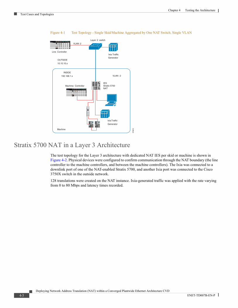
The test topology for the Layer 2 architecture is shown in Figure 4-1. Physical devices were configured to confirm communication through the NAT boundary (The line controller to the machine controller). The Ixia was connected to a downlink port of the NAT-enabled Stratix 5700, and another Ixia port was connected to the Stratix 8000™ in the outside network.
128 translations were created on the NAT instance. Ixia-generated traffic was applied with the rate varying from 0 to 80 Mbps and latency times recorded.
POINT Digital output module 1734-OB8 3.022
ETAP DLR module 1783-ETAP 2.2
Table 4-1 Test Hardware (continued)
Role Product / Catalog Number SW Version
4-2Deploying Network Address Translation (NAT) within a Converged Plantwide Ethernet Architecture CVD
ENET-TD007B-EN-P
Chapter 4 Testing the ArchitectureTest Cases and Topologies
Figure 4-1 Test Topology - Single Skid/Machine Aggregated by One NAT Switch, Single VLAN
Stratix 5700 NAT in a Layer 3 Architecture
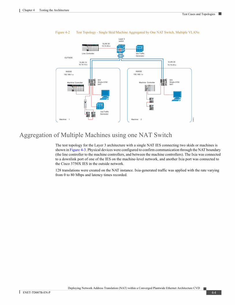
The test topology for the Layer 3 architecture with dedicated NAT IES per skid or machine is shown in Figure 4-2. Physical devices were configured to confirm communication through the NAT boundary (the line controller to the machine controllers, and between the machine controllers). The Ixia was connected to a downlink port of one of the NAT-enabled Stratix 5700, and another Ixia port was connected to the Cisco 3750X switch in the outside network.
128 translations were created on the NAT instance. Ixia-generated traffic was applied with the rate varying from 0 to 80 Mbps and latency times recorded.
Machine
Machine Controller
VLAN 2
INSIDE
192.168.1.x
OUTSIDE
10.10.10.x
VLAN 2
Line Controller
IESStratix 5700NAT
Ixia Traffic
Generator
Ixia Traffic
Generator
3746
12
Layer 2 switch
4-3Deploying Network Address Translation (NAT) within a Converged Plantwide Ethernet Architecture CVD
ENET-TD007B-EN-P
Chapter 4 Testing the ArchitectureTest Cases and Topologies
Figure 4-2 Test Topology - Single Skid/Machine Aggregated by One NAT Switch, Multiple VLANs
Aggregation of Multiple Machines using one NAT Switch
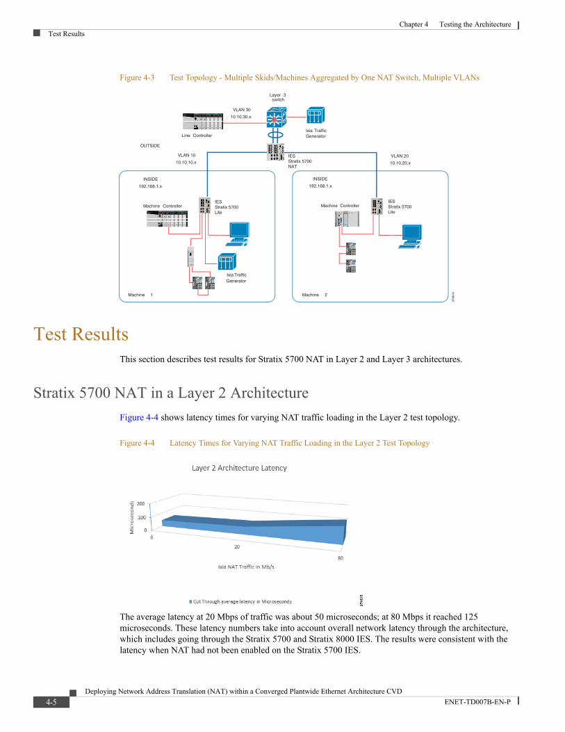
The test topology for the Layer 3 architecture with a single NAT IES connecting two skids or machines is shown in Figure 4-3. Physical devices were configured to confirm communication through the NAT boundary (the line controller to the machine controllers, and between the machine controllers). The Ixia was connected to a downlink port of one of the IES on the machine-level network, and another Ixia port was connected to the Cisco 3750X IES in the outside network.
128 translations were created on the NAT instance. Ixia-generated traffic was applied with the rate varying from 0 to 80 Mbps and latency times recorded.
Machine 1
IESStratix 5700NAT
VLAN 1010.10.10.x
Machine 2
VLAN 3010.10.30.x
IESStratix 5700NAT
Line Controller
INSIDE
192.168.1.x
INSIDE
192.168.1.x
OUTSIDE
VLAN 20
10.10.20.x
Ixia TrafficGenerator
Machine Controller Machine Controller
Ixia Traffic Generator
3746
13
Layer 3switch
4-4Deploying Network Address Translation (NAT) within a Converged Plantwide Ethernet Architecture CVD
ENET-TD007B-EN-P
Chapter 4 Testing the ArchitectureTest Results
Figure 4-3 Test Topology - Multiple Skids/Machines Aggregated by One NAT Switch, Multiple VLANs
Test ResultsThis section describes test results for Stratix 5700 NAT in Layer 2 and Layer 3 architectures.
Stratix 5700 NAT in a Layer 2 Architecture
Figure 4-4 shows latency times for varying NAT traffic loading in the Layer 2 test topology.
Figure 4-4 Latency Times for Varying NAT Traffic Loading in the Layer 2 Test Topology
The average latency at 20 Mbps of traffic was about 50 microseconds; at 80 Mbps it reached 125 microseconds. These latency numbers take into account overall network latency through the architecture, which includes going through the Stratix 5700 and Stratix 8000 IES. The results were consistent with the latency when NAT had not been enabled on the Stratix 5700 IES.
Machine 1
IESStratix 5700NAT
VLAN 10
10.10.10.x
Machine 2
VLAN 30
10.10.30.x
Line Controller
INSIDE
192.168.1.x
INSIDE
192.168.1.x
OUTSIDE
VLAN 20
10.10.20.x
Ixia Traffic Generator
Machine Controller Machine Controller
Ixia TrafficGenerator
IESStratix 5700Lite
IESStratix 5700Lite
3746
14
Layer 3 switch
4-5Deploying Network Address Translation (NAT) within a Converged Plantwide Ethernet Architecture CVD
ENET-TD007B-EN-P
Chapter 4 Testing the ArchitectureTest Results
Stratix 5700 NAT in a Layer 3 Architecture
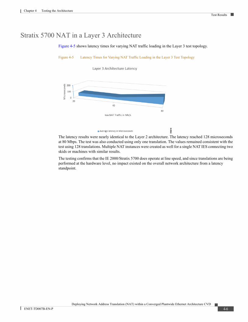
Figure 4-5 shows latency times for varying NAT traffic loading in the Layer 3 test topology.
Figure 4-5 Latency Times for Varying NAT Traffic Loading in the Layer 3 Test Topology
The latency results were nearly identical to the Layer 2 architecture. The latency reached 128 microseconds at 80 Mbps. The test was also conducted using only one translation. The values remained consistent with the test using 128 translations. Multiple NAT instances were created as well for a single NAT IES connecting two skids or machines with similar results.
The testing confirms that the IE 2000/Stratix 5700 does operate at line speed, and since translations are being performed at the hardware level, no impact existed on the overall network architecture from a latency standpoint.
4-6Deploying Network Address Translation (NAT) within a Converged Plantwide Ethernet Architecture CVD
ENET-TD007B-EN-P
Chapter 4 Testing the ArchitectureTest Results
Cisco is the worldwide leader in networking that transforms how people connect, communicate and collaborate. Information about Cisco can be found at www.cisco.com. For ongoing news, please go to http://newsroom.cisco.com. Cisco equipment in Europe is supplied by Cisco Systems International BV, a wholly owned subsidiary of Cisco Systems, Inc.
www.cisco.com
Americas HeadquartersCisco Systems, Inc.San Jose, CA
Asia Pacific HeadquartersCisco Systems (USA) Pte. Ltd.Singapore
Europe HeadquartersCisco Systems International BVAmsterdam, The Netherlands
Cisco has more than 200 offices worldwide. Addresses, phone numbers, and fax numbers are listed on the Cisco Website at www.cisco.com/go/offices.
Cisco and the Cisco logo are trademarks or registered trademarks of Cisco and/or its affiliates in the U.S. and other countries. To view a list of Cisco trademarks, go to this URL:www.cisco.com/go/trademarks. Third-party trademarks mentioned are the property of their respective owners. The use of the word partner does not imply a partnership relationship betweenCisco and any other company. (1110R)
Rockwell Automation is a leading provider of power, control and information solutions that enable customers to get products to market faster, reduce their total cost of ownership, better utilize plant assets, and minimize risks in their manufacturing environments.
www.rockwellautomation.com
Americas:Rockwell Automation1201 South Second Street Milwaukee, WI 53204-2496 USA Tel: (1) 414.382.2000, Fax: (1) 414.382.4444
Asia Pacific:Rockwell AutomationLevel 14, Core F, Cyberport 3 100 Cyberport Road, Hong Kong Tel: (852) 2887 4788, Fax: (852) 2508 1846
Europe/Middle East/Africa: Rockwell AutomationNV, Pegasus Park, De Kleetlaan 12a 1831 Diegem, Belgium Tel: (32) 2 663 0600, Fax: (32) 2 663 0640
Allen-Bradley, ControlLogix, FactoryTalk, POINT I/O, Rockwell Automation, Stratix 5700, Stratix 8000 and Studio 5000 are trademarks of Rockwell Automation.
EtherNet/IP is a trademark of the ODVA. Microsoft is a trademark of the Microsoft Corporation.
© 2016 Cisco Systems, Inc. and Rockwell Automation, Inc. All rights reserved.
Publication ENET-TD007B-EN-P— April 2016


