Chapter 16 Deploying Microsoft Enterprise Desktop Virtualization In the previous chapter we reviewed deploying Microsoft VDI, a server-hosted desktop virtualization solution. In this chapter we will review deploying Microsoft Enterprise Desktop Virtualization (MED-V), a managed client-hosted desktop virtualization solution. The chapter includes a review of considerations for planning a deployment, guidance for conducting a Proof of Concept (POC), an overview of required server and client solution components, and step-by-step instructions for installing and configuring MED-V in a test environment. In this chapter, you will learn to: ◆ Install and configure the MED-V Management Server ◆ Create and prepare a MED-V test image ◆ Create and configure a MED-V Workspace image ◆ Deploy a MED-V Workspace image ◆ Generate MED-V reports Planning Considerations for a MED-V Deployment At a high level, the process and steps of planning for a MED-V deployment are similar to the approach we took in our last chapter, but the specific details for each step are different. As a review, the planning steps included assessing the current environment, determining needs and requirements, defining the project scope, creating an architectural design, conducting a POC, and continuing on with a pilot and later a full deployment. Let’s review these planning steps and their specific MED-V considerations. Assessing Your Environment Before an organization deploys a MED-V solution, it’s important that they conduct an assess- ment of their current desktop environment. The assessment would include reviewing desktop hardware, operating systems, applications, user data and settings, network infrastructure, and management tools. A review of the desktop hardware environment, the processor family and type, memory configuration, and hard disk storage of each desktop should be made and recorded. In addition, the Windows client operating system and versions running on each desktop, either
Transcript
Chapter 16
Deploying Microsoft EnterpriseDesktop Virtualization
In the previous chapter we reviewed deploying Microsoft VDI, a server-hosted desktopvirtualization solution. In this chapter we will review deploying Microsoft Enterprise DesktopVirtualization (MED-V), a managed client-hosted desktop virtualization solution. The chapterincludes a review of considerations for planning a deployment, guidance for conducting aProof of Concept (POC), an overview of required server and client solution components, andstep-by-step instructions for installing and configuring MED-V in a test environment.
In this chapter, you will learn to:
◆ Install and configure the MED-V Management Server
◆ Create and prepare a MED-V test image
◆ Create and configure a MED-V Workspace image
◆ Deploy a MED-V Workspace image
◆ Generate MED-V reports
Planning Considerations for a MED-V DeploymentAt a high level, the process and steps of planning for a MED-V deployment are similar to theapproach we took in our last chapter, but the specific details for each step are different. As areview, the planning steps included assessing the current environment, determining needs andrequirements, defining the project scope, creating an architectural design, conducting a POC,and continuing on with a pilot and later a full deployment. Let’s review these planning stepsand their specific MED-V considerations.
Assessing Your EnvironmentBefore an organization deploys a MED-V solution, it’s important that they conduct an assess-ment of their current desktop environment. The assessment would include reviewing desktophardware, operating systems, applications, user data and settings, network infrastructure, andmanagement tools.
A review of the desktop hardware environment, the processor family and type, memoryconfiguration, and hard disk storage of each desktop should be made and recorded. Inaddition, the Windows client operating system and versions running on each desktop, either
478 CHAPTER 16 DEPLOYING MICROSOFT ENTERPRISE DESKTOP VIRTUALIZATION
physically or as virtual machines, needs to be identified and recorded. All of this informationis required in determining whether the current desktops meet the MED-V client systemrequirements and if a hardware or software upgrade may be needed.
Another necessary step is to review which corporate applications are running on each desk-top, along with their specific hardware and software dependencies. Each application will needto be evaluated to determine if it can run in a virtual machine and the application vendor sup-ports it.
An assessment of the desktop network environment is also important. Understanding wherethe desktops are located (main, distributed, or home office) and their associated network band-width and latency will help in determining the location of MED-V server infrastructure andhow images will be initially deployed and updated.
Understanding what processes and tools are used to manage the desktop environment alongwith identifying current management challenges are essential. An organization will need todetermine if their existing management process and tools can be used to manage the MED-Vclient environment or if new processes or tools will need to be evaluated and implemented. Inaddition, current desktop management challenges should be addressed prior to introducing anew desktop solution into the environment.
As mentioned before, Microsoft has assessment tools that can be used to assist an orga-nization in this effort. The Microsoft Assessment and Planning Toolkit can be found athttp://technet.microsoft.com/en-us/solutionaccelerators.
Determining Needs and RequirementsThe next step for the organization is to determine their requirements for a MED-V implementa-tion. The data collected during the assessment step can help with this process. An organizationwill need to ask what problem or problems they are trying to solve. For example, is the organi-zation planning to migrate from the Windows XP to Windows 7 operating system and does itneed a solution to remediate potential application-to-OS compatibility problems? Are they con-sidering deploying corporate-managed VMs to nonmanaged or employee-owned PCs? Maybethey would like to improve their desktop business-continuity and disaster-recovery capabili-ties by having the ability to rapidly and easily move a desktop PC image from one PC deviceto another in the event of a hardware failure, stolen PC, or disaster. This analysis will help anorganization determine whether MED-V is the most appropriate solution to meet their require-ments and help guide the architecture design and implementation of the solution.
Defining Project ScopeAfter the organization has conducted an assessment of their environment and identified theproblem(s) they are trying to solve and their specific needs, the next step is to define the scopeof the MED-V deployment project. Some of the areas to consider when defining the projectscope include which scenario(s) to implement first, the type and number of users and groups totarget, which locations to include, and whether this effort should be part of a larger project. Allof these questions should be answered to help develop the initial, mid-, and long-term scopesof the MED-V deployment project.
An organization may choose to implement the MED-V deployment project in phases, witheach phase targeting a specific solution scenario and expanding the scope of users and groupsover time. They may decide to initially implement a MED-V solution as a way to improvethe disaster-recovery capabilities of the organization. They may also choose to use MED-V toremediate application-to-operating system compatibility issues to support a Windows Vista orWindows 7 deployment project. In this case, the MED-V project would be part of the larger
PLANNING CONSIDERATIONS FOR A MED-V DEPLOYMENT 479
Windows migration project and closely aligned with that project scope. A future plan couldalso include implementing a MED-V solution as a more agile way to deploy corporate desktopimages to employee-owned or unmanaged desktops. Whatever the reason(s) for deploying aMED-V solution, the organization will need to define and closely align the scope of the projectwith its goals and needs.
Microsoft Consulting Services and Microsoft Partners can assist organizations with definingthe MED-V project scope and overall planning efforts. More information regarding MicrosoftConsulting Services and Partner offerings can be found at http://www.microsoft.com/services/microsoftservices and http://www.microsoft.com/virtualization/partners.
Creating a Solution Design and ArchitectureOnce an organization has completed the above steps, from conducting the assessment todefining the project scope, they are ready to design the MED-V solution architecture. A MED-Varchitecture consists of multiple server components that make up the overall solution. Thenumber of servers needed to support a MED-V solution will depend on the organization’scurrent IT environment and requirements. The architectural design factors include the numberof users, location of users, Active Directory domain design, number of Workspace images,existing management infrastructure, security and regulatory requirements, and High Availabil-ity needs. Let’s explore some of these factors and their effect on designing a MED-V solutionarchitecture.
Today, Microsoft MED-V v1 is positioned and supported only for desktops that are part ofan Active Directory Domain Services environment. Microsoft is planning to support nondo-main, unmanaged desktops with the next version of MED-V planned for release in 2010. AMED-V solution is called an instance and consists of a Management Server, Image RepositoryServer, and Reporting Server. A MED-V Management Server can belong to only one MED-Vinstance at a time, but the MED-V Repository Server and Database Server can be shared acrossmultiple MED-V Management Servers. Microsoft recommends no more than 5,000 concurrentusers be supported per MED-V instance. If an organization is planning to support more than5,000 concurrent users, another MED-V instance will need to be added for each additional 5,000users. In addition, if the organization has security or regulatory requirements that mandatethe separation of specific MED-V Workspace images, they can implement additional MED-Vinstances to support those requirements.
The MED-V Management Server should be centrally located to provide reliable networkaccess for its clients. A MED-V client regularly connects to the MED-V Management Serverto send status and event information once a minute. The MED-V client also checks with theMED-V Management Server for Workspace updates every 15 minutes and image updates everyfour hours. If a client is unable to connect to a MED-V Management Server, the status andevent information is queued on the client until it is able to reconnect. Microsoft does not sup-port using Failover Clustering for MED-V Management Server, so it’s important to create astandby MED-V Management Server that can be brought online in the case of server failure.This is especially true if the MED-V Workspace is configured to require the client to be onlineand authenticated in order to use the MED-V Workspace. It is possible to implement MED-VManagement Server on two servers. More information about implementing this type of failoversupport can be found in the MED-V manual.
The MED-V Management Server stores Workspace configuration metadata, which is30 KB per Workspace. To determine the disk storage requirements for storing Workspacemetadata on the MED-V Management Server, multiply the number of Workspaces by 30 KB.For example, if you have 20 Workspaces, you would multiply 20 by 30 KB, which equals
480 CHAPTER 16 DEPLOYING MICROSOFT ENTERPRISE DESKTOP VIRTUALIZATION
600 KB. The MED-V Management Server can be backed up and restored to the same serveror a backup server using Microsoft System Center Data Protection Manager (SCDPM) oranother backup and restore solution. Four XML files make up the server configurationfiles: ClientSettings.xml, ConfigurationFiles.xml, OrganizationalPolicy.xml, andWorkspaceKeys.xml. The location for the data to back up is drive letter:\microsoftenterprise desktop Virtualization\servers\serverconfiguration.
As mentioned earlier, a Repository Server consists of a Web Server (IIS) and a file serverthat stores the images on a file share. The number of Web Servers (IIS) and file servers usedin a MED-V solution instance will depend on the number of concurrent users, the size andnumber of the MED-V images, deployment and update frequency, the user location, networkbandwidth, and other factors. Multiple Web Servers (IIS) can be used for a MED-V solutioninstance and load balanced to provide the appropriate level of scalability and performance. Theplacement of the Repository Servers should be close to the clients, avoiding WAN connections.This is important for the initial deployment of the MED-V image and also image updates. Thedisk storage requirements for the Image Repository are determined by identifying the num-ber and size of MED-V images that will be supported on a given repository. Backing up theMED-V images is also important and can be accomplished by using SCDPM or another backupand restore solution.
The Med-V Database Server stores client activity and event information. The size of an eventsent by a client is around 200 bytes. The MED-V Database Server database storage requirementsare determined by the number of MED-V clients, multiplied by the number of events sent byeach client per day. Other database size factors include how long the data will be stored andthe allocation of additional space for unknown events or circumstances.
Organizations will need to determine how the MED-V client software and images will bedeployed and updated on the client. There are different options to choose from, including usingthe MED-V solution infrastructure, existing client management solutions, and removable media(DVD and USB storage). For example, an organization could deploy the MED-V client softwareby making it part of their corporate Windows image, deploying it using ESD or with removablemedia. The initial MED-V image can be deployed to the client by using the MED-V Manage-ment Server, prestaging it to the client using ESD or by removable media (DVD and USB stor-age). The Med-V images will also need to be updated, which can be accomplished by using theMED-V Management Server. Some organizations may also decide to update the client operatingsystem and applications running in the MED-V image by using their corporate ESD solution.
Implementing a MED-V POCOnce the solution design and architecture are completed, the next step is to test the solution ina Proof of Concept (POC) lab environment. POCs are where the rubber meets the road and canvary in goals, scope, time frame, and outcome. It’s important to conduct a well-organized POC,focusing only on the goals and scope agreed on, involving the right resources, and document-ing the entire process from start to finish, so that this information can be reviewed and utilizedto support later project efforts.
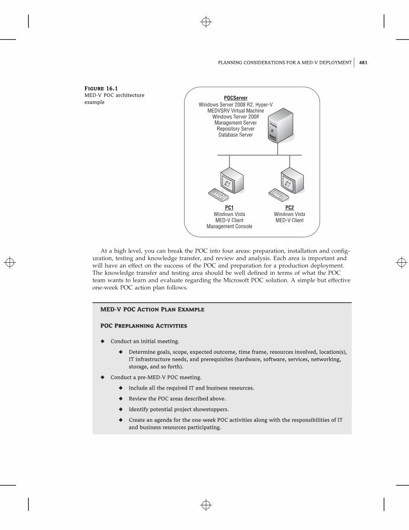
Depending on the goals of the POC, the architecture and server configuration of this envi-ronment can be implemented on a much smaller scale than a pilot or production deploymentof the solution. For example, a typical MED-V POC involves one physical server and one totwo PCs. The server would support the MED-V Management Server and Image Repository,and the PCs would support the MED-V Management Console and MED-V Client. An exampleMED-V POC server configuration is shown along with the MED-V POC architecture examplein Figure 16.1.
PLANNING CONSIDERATIONS FOR A MED-V DEPLOYMENT 481
Figure 16.1
MED-V POC architectureexample
POCServerWindows Server 2008 R2, Hyper-V
MEDVSRV Virtual MachineWindows Server 2008Management ServerRepository ServerDatabase Server
PC1Windows VistaMED-V Client
Management Console
PC2Windows VistaMED-V Client
At a high level, you can break the POC into four areas: preparation, installation and config-uration, testing and knowledge transfer, and review and analysis. Each area is important andwill have an effect on the success of the POC and preparation for a production deployment.The knowledge transfer and testing area should be well defined in terms of what the POCteam wants to learn and evaluate regarding the Microsoft POC solution. A simple but effectiveone-week POC action plan follows.
MED-V POC Action Plan Example
POC Preplanning Activities
◆ Conduct an initial meeting.
◆ Determine goals, scope, expected outcome, time frame, resources involved, location(s),IT infrastructure needs, and prerequisites (hardware, software, services, networking,storage, and so forth).
◆ Conduct a pre-MED-V POC meeting.
◆ Include all the required IT and business resources.
◆ Review the POC areas described above.
◆ Identify potential project showstoppers.
◆ Create an agenda for the one-week POC activities along with the responsibilities of ITand business resources participating.
482 CHAPTER 16 DEPLOYING MICROSOFT ENTERPRISE DESKTOP VIRTUALIZATION
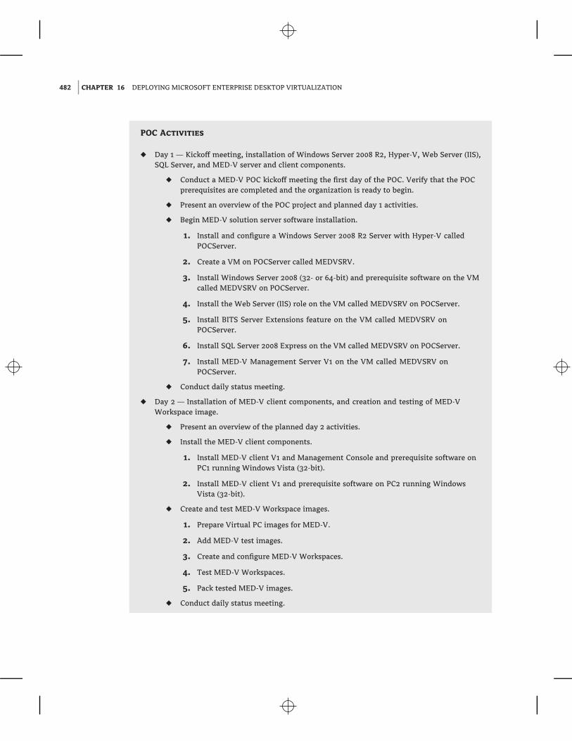
POC Activities
◆ Day 1 — Kickoff meeting, installation of Windows Server 2008 R2, Hyper-V, Web Server (IIS),SQL Server, and MED-V server and client components.
◆ Conduct a MED-V POC kickoff meeting the first day of the POC. Verify that the POCprerequisites are completed and the organization is ready to begin.
◆ Present an overview of the POC project and planned day 1 activities.
◆ Begin MED-V solution server software installation.
1. Install and configure a Windows Server 2008 R2 Server with Hyper-V calledPOCServer.
2. Create a VM on POCServer called MEDVSRV.
3. Install Windows Server 2008 (32- or 64-bit) and prerequisite software on the VMcalled MEDVSRV on POCServer.
4. Install the Web Server (IIS) role on the VM called MEDVSRV on POCServer.
5. Install BITS Server Extensions feature on the VM called MEDVSRV onPOCServer.
6. Install SQL Server 2008 Express on the VM called MEDVSRV on POCServer.
7. Install MED-V Management Server V1 on the VM called MEDVSRV onPOCServer.
◆ Conduct daily status meeting.
◆ Day 2 — Installation of MED-V client components, and creation and testing of MED-VWorkspace image.
◆ Present an overview of the planned day 2 activities.
◆ Install the MED-V client components.
1. Install MED-V client V1 and Management Console and prerequisite software onPC1 running Windows Vista (32-bit).
2. Install MED-V client V1 and prerequisite software on PC2 running WindowsVista (32-bit).
◆ Create and test MED-V Workspace images.
1. Prepare Virtual PC images for MED-V.
2. Add MED-V test images.
3. Create and configure MED-V Workspaces.
4. Test MED-V Workspaces.
5. Pack tested MED-V images.
◆ Conduct daily status meeting.
INSTALLING THE MED-V SOLUTION 483
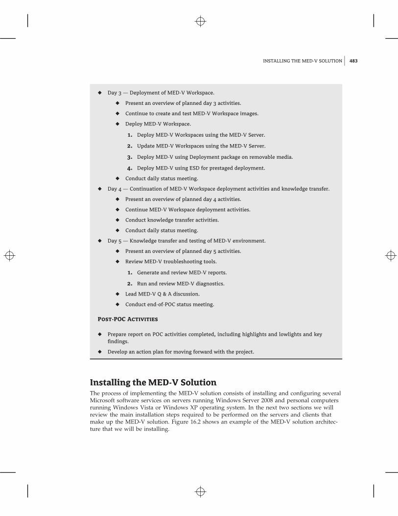
◆ Day 3 — Deployment of MED-V Workspace.
◆ Present an overview of planned day 3 activities.
◆ Continue to create and test MED-V Workspace images.
◆ Deploy MED-V Workspace.
1. Deploy MED-V Workspaces using the MED-V Server.
2. Update MED-V Workspaces using the MED-V Server.
3. Deploy MED-V using Deployment package on removable media.
4. Deploy MED-V using ESD for prestaged deployment.
◆ Conduct daily status meeting.
◆ Day 4 — Continuation of MED-V Workspace deployment activities and knowledge transfer.
◆ Present an overview of planned day 4 activities.
◆ Continue MED-V Workspace deployment activities.
◆ Conduct knowledge transfer activities.
◆ Conduct daily status meeting.
◆ Day 5 — Knowledge transfer and testing of MED-V environment.
◆ Present an overview of planned day 5 activities.
◆ Review MED-V troubleshooting tools.
1. Generate and review MED-V reports.
2. Run and review MED-V diagnostics.
◆ Lead MED-V Q & A discussion.
◆ Conduct end-of-POC status meeting.
Post-POC Activities
◆ Prepare report on POC activities completed, including highlights and lowlights and keyfindings.
◆ Develop an action plan for moving forward with the project.
Installing the MED-V SolutionThe process of implementing the MED-V solution consists of installing and configuring severalMicrosoft software services on servers running Windows Server 2008 and personal computersrunning Windows Vista or Windows XP operating system. In the next two sections we willreview the main installation steps required to be performed on the servers and clients thatmake up the MED-V solution. Figure 16.2 shows an example of the MED-V solution architec-ture that we will be installing.
484 CHAPTER 16 DEPLOYING MICROSOFT ENTERPRISE DESKTOP VIRTUALIZATION
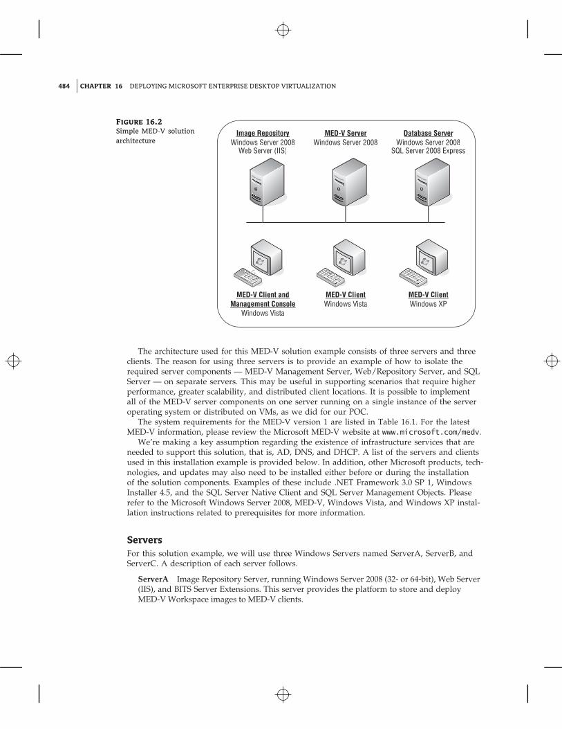
Figure 16.2
Simple MED-V solutionarchitecture
Image RepositoryWindows Server 2008
Web Server (IIS)
MED-V Client andManagement Console
Windows Vista
MED-V ClientWindows Vista
g p y MED-V ServerWindows Server 2008
Database ServerWindows Server 2008
SQL Server 2008 Express
gMED-V ClientWindows XP
The architecture used for this MED-V solution example consists of three servers and threeclients. The reason for using three servers is to provide an example of how to isolate therequired server components — MED-V Management Server, Web/Repository Server, and SQLServer — on separate servers. This may be useful in supporting scenarios that require higherperformance, greater scalability, and distributed client locations. It is possible to implementall of the MED-V server components on one server running on a single instance of the serveroperating system or distributed on VMs, as we did for our POC.
The system requirements for the MED-V version 1 are listed in Table 16.1. For the latestMED-V information, please review the Microsoft MED-V website at www.microsoft.com/medv.
We’re making a key assumption regarding the existence of infrastructure services that areneeded to support this solution, that is, AD, DNS, and DHCP. A list of the servers and clientsused in this installation example is provided below. In addition, other Microsoft products, tech-nologies, and updates may also need to be installed either before or during the installationof the solution components. Examples of these include .NET Framework 3.0 SP 1, WindowsInstaller 4.5, and the SQL Server Native Client and SQL Server Management Objects. Pleaserefer to the Microsoft Windows Server 2008, MED-V, Windows Vista, and Windows XP instal-lation instructions related to prerequisites for more information.
ServersFor this solution example, we will use three Windows Servers named ServerA, ServerB, andServerC. A description of each server follows.
ServerA Image Repository Server, running Windows Server 2008 (32- or 64-bit), Web Server(IIS), and BITS Server Extensions. This server provides the platform to store and deployMED-V Workspace images to MED-V clients.
INSTALLING THE MED-V SOLUTION 485
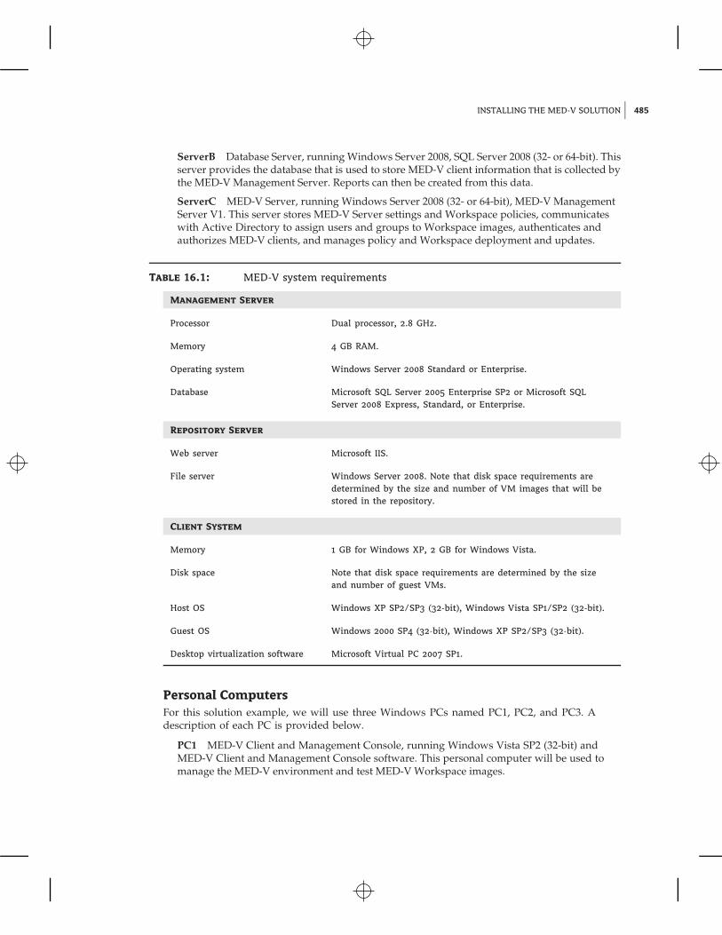
ServerB Database Server, running Windows Server 2008, SQL Server 2008 (32- or 64-bit). Thisserver provides the database that is used to store MED-V client information that is collected bythe MED-V Management Server. Reports can then be created from this data.
ServerC MED-V Server, running Windows Server 2008 (32- or 64-bit), MED-V ManagementServer V1. This server stores MED-V Server settings and Workspace policies, communicateswith Active Directory to assign users and groups to Workspace images, authenticates andauthorizes MED-V clients, and manages policy and Workspace deployment and updates.
Table 16.1: MED-V system requirements
Management Server
Processor Dual processor, 2.8 GHz.
Memory 4 GB RAM.
Operating system Windows Server 2008 Standard or Enterprise.
Database Microsoft SQL Server 2005 Enterprise SP2 or Microsoft SQLServer 2008 Express, Standard, or Enterprise.
Repository Server
Web server Microsoft IIS.
File server Windows Server 2008. Note that disk space requirements aredetermined by the size and number of VM images that will bestored in the repository.
Client System
Memory 1 GB for Windows XP, 2 GB for Windows Vista.
Disk space Note that disk space requirements are determined by the sizeand number of guest VMs.
Host OS Windows XP SP2/SP3 (32-bit), Windows Vista SP1/SP2 (32-bit).
Guest OS Windows 2000 SP4 (32-bit), Windows XP SP2/SP3 (32-bit).
Desktop virtualization software Microsoft Virtual PC 2007 SP1.
Personal ComputersFor this solution example, we will use three Windows PCs named PC1, PC2, and PC3. Adescription of each PC is provided below.
PC1 MED-V Client and Management Console, running Windows Vista SP2 (32-bit) andMED-V Client and Management Console software. This personal computer will be used tomanage the MED-V environment and test MED-V Workspace images.
486 CHAPTER 16 DEPLOYING MICROSOFT ENTERPRISE DESKTOP VIRTUALIZATION
PC2 MED-V Client running Windows Vista SP2 (32-bit) and MED-V Client software. Thispersonal computer will be used to download and run MED-V Workspaces.
PC3 MED-V Client running Windows XP SP3 (32-bit) and MED-V Client software. This per-sonal computer will be used to download and run MED-V Workspaces.
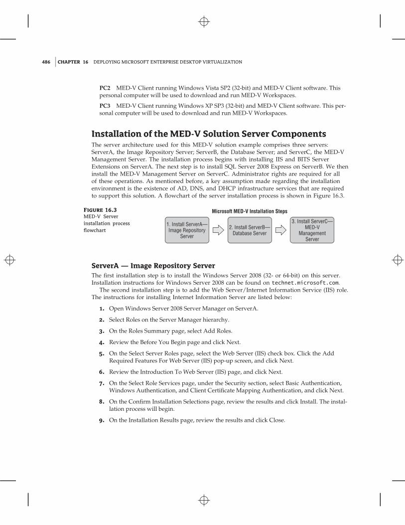
Installation of the MED-V Solution Server ComponentsThe server architecture used for this MED-V solution example comprises three servers:ServerA, the Image Repository Server; ServerB, the Database Server; and ServerC, the MED-VManagement Server. The installation process begins with installing IIS and BITS ServerExtensions on ServerA. The next step is to install SQL Server 2008 Express on ServerB. We theninstall the MED-V Management Server on ServerC. Administrator rights are required for allof these operations. As mentioned before, a key assumption made regarding the installationenvironment is the existence of AD, DNS, and DHCP infrastructure services that are requiredto support this solution. A flowchart of the server installation process is shown in Figure 16.3.
Figure 16.3
MED-V Serverinstallation processflowchart
1. Install ServerA—Image Repository
Server
2. Install ServerB—Database Server
3. Install ServerC—MED-V
ManagementServer
Microsoft MED-V Installation Steps
ServerA — Image Repository ServerThe first installation step is to install the Windows Server 2008 (32- or 64-bit) on this server.Installation instructions for Windows Server 2008 can be found on technet.microsoft.com.
The second installation step is to add the Web Server/Internet Information Service (IIS) role.The instructions for installing Internet Information Server are listed below:
1. Open Windows Server 2008 Server Manager on ServerA.
2. Select Roles on the Server Manager hierarchy.
3. On the Roles Summary page, select Add Roles.
4. Review the Before You Begin page and click Next.
5. On the Select Server Roles page, select the Web Server (IIS) check box. Click the AddRequired Features For Web Server (IIS) pop-up screen, and click Next.
6. Review the Introduction To Web Server (IIS) page, and click Next.
7. On the Select Role Services page, under the Security section, select Basic Authentication,Windows Authentication, and Client Certificate Mapping Authentication, and click Next.
8. On the Confirm Installation Selections page, review the results and click Install. The instal-lation process will begin.
9. On the Installation Results page, review the results and click Close.
INSTALLATION OF THE MED-V SOLUTION SERVER COMPONENTS 487
The third installation step adds the BITS Server Extensions feature to the server. The stepsfor installing this feature are as follows:
1. Open Windows Server 2008 Server Manager on ServerA.
2. Select Features on the Server Manager hierarchy.
3. On the Features Summary page, click Add Feature.
4. On the Select Features page, select the BITS Server Extensions check box. The Add RoleServices Required For Background Intelligent Transfer Service (BITS)? pop-up screen willappear. Click Add Required Role Services, and then click Next.
5. On the Introduction To Web Server (IIS) page, click Next.
6. On the Select Role Services page, click Next.
7. On the Confirm Installation Selections page, review the results and click Install. The instal-lation process will begin.
8. On the Installation Results page, review the results and click Close.
The installation steps for ServerA, the Image Repository Server are now complete. The con-figuration steps for this server are provided in the upcoming section called ‘‘Configuration ofthe MED-V Solution Server Components.’’
ServerB — Database ServerThe first step is to install the Windows Server 2008 (32- or 64-bit) on this server. Installationinformation for Windows Server 2008 can be found on technet.microsoft.com.
The second step is to install SQL Server. For this installation example we will use SQLServer 2008 Express. Note that SQL Server 2005 Enterprise and SQL Server 2008 Standard andEnterprise may also be used and are a better choice for production deployments. The steps forinstalling the SQL Server 2008 Express are listed below:
1. Install .NET Framework 3.0 SP 1. SQL Server 2008 Express Setup requires .NETFramework 3.0 SP1 to be installed. .NET Framework 3.0 SP1 can be downloaded atwww.microsoft.com/downloads.
2. Install Windows Installer 4.5. SQL Server 2008 Express Setup requires WindowsInstaller 4.5 to be installed. Windows Installer 4.5 can be downloaded atwww.microsoft.com/downloads.
3. The next step is to install SQL Server 2008 Express. SQL Server 2008 Express can be down-loaded from www.microsoft.com/downloads. Follow these installation steps:
a. Run SQL Server Express Setup.b. On the SQL Server Installation Center page, select Installation.c. Select New SQL Server Stand-alone Installation or Add Features To An Existing Instal-
lation. The Setup Support Rules process will run and identify any problems. If anyfailures are identified, correct the issues and rerun this process. If no problems are iden-tified, click OK.
d. On the Product Key page, click Next since SQL Server Express is a free product.
488 CHAPTER 16 DEPLOYING MICROSOFT ENTERPRISE DESKTOP VIRTUALIZATION
e. Review the License Terms, and if you accept them, select the I Accept The LicenseTerms check box.
f. On the Setup Support Files page, click Install.g. For the Setup Support Rules step, see if failures were identified. If failures were iden-
tified, correct the issues and rerun this process. If no problems were identified, clickNext.
h. For the Feature Selection step, select the Database Engine Services check box and clickNext.
i. For the Instance Configuration step, accept the default settings and click Next.j. For the Disk Space Requirements step, review the disk usage summary and click
Next.k. For the Server Configuration step, there are two tabs: Service Accounts and Colla-
tion. For Service Accounts, select NT Authority � System from the Account Namedrop-down list. Accept the default setting for SQL Server Browser. For the Collationsettings, accept the defaults. Click Next.
l. For the Database Engine Configuration, Account Provisioning, select Mixed Mode, andenter a password for the built-in SQL Server administrator account (SA). Specify SQLServer administrators by clicking Add Current User. Accept the default settings forData Directories, User Instances, and FILESTREAM, and click Next.
m. For the Error And Usage Reporting step, accept the default settings and click Next.n. For the Installation Rules step, see if failures were identified. If failures were identi-
fied, correct the issues and rerun this process. If no problems were identified, clickNext.
o. Review the Ready To Install information and click Install. The installation process willbegin.
p. When the installation has completed successfully, click Next.q. Review the information on the completed page, and click Close.
The installation steps for ServerB, the Database Server are now complete. The configurationsteps for this server are provided in the upcoming section called ‘‘Configuration of the MED-VSolution Server Components.’’
ServerC — MED-V Management ServerThe first step is to install Windows Server 2008 (32- or 64-bit) on this server. Installation instruc-tions for Windows Server 2008 can be found on technet.microsoft.com.
The next step is to install the MED-V Management Server. The steps for installing theMED-V Management Server V1 are listed below.
1. Run the appropriate MED-V Server Windows Installer package,MED-V_serverx_86_1.0.72.msi for x86 or MED-V_server_x64_1.0.72.msi for x64.
2. Review the MED-V Server Installation Wizard Welcome screen, and click Next.
3. Review the MED-V License Agreement. If you accept the licensing terms, click Next.
4. Review the Install Destination Folder setting, and click Next.
5. On the Ready To Install The Program screen, click Install.
6. On the MED-V Wizard Completed screen, deselect Launch MED-V Server ConfigurationManager, and click Finish.
INSTALLATION OF THE MED-V SOLUTION CLIENT COMPONENTS 489
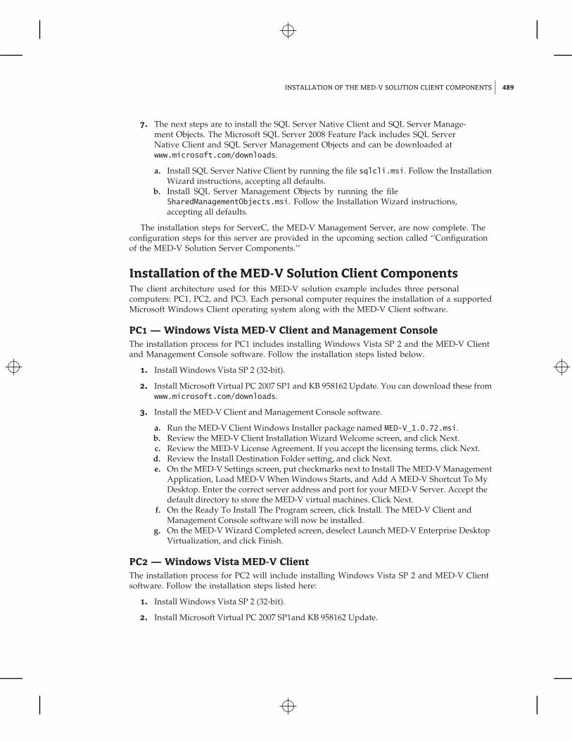
7. The next steps are to install the SQL Server Native Client and SQL Server Manage-ment Objects. The Microsoft SQL Server 2008 Feature Pack includes SQL ServerNative Client and SQL Server Management Objects and can be downloaded atwww.microsoft.com/downloads.
a. Install SQL Server Native Client by running the file sqlcli.msi. Follow the InstallationWizard instructions, accepting all defaults.
b. Install SQL Server Management Objects by running the fileSharedManagementObjects.msi. Follow the Installation Wizard instructions,accepting all defaults.
The installation steps for ServerC, the MED-V Management Server, are now complete. Theconfiguration steps for this server are provided in the upcoming section called ‘‘Configurationof the MED-V Solution Server Components.’’
Installation of the MED-V Solution Client ComponentsThe client architecture used for this MED-V solution example includes three personalcomputers: PC1, PC2, and PC3. Each personal computer requires the installation of a supportedMicrosoft Windows Client operating system along with the MED-V Client software.
PC1 — Windows Vista MED-V Client and Management ConsoleThe installation process for PC1 includes installing Windows Vista SP 2 and the MED-V Clientand Management Console software. Follow the installation steps listed below.
1. Install Windows Vista SP 2 (32-bit).
2. Install Microsoft Virtual PC 2007 SP1 and KB 958162 Update. You can download these fromwww.microsoft.com/downloads.
3. Install the MED-V Client and Management Console software.
a. Run the MED-V Client Windows Installer package named MED-V_1.0.72.msi.b. Review the MED-V Client Installation Wizard Welcome screen, and click Next.c. Review the MED-V License Agreement. If you accept the licensing terms, click Next.d. Review the Install Destination Folder setting, and click Next.e. On the MED-V Settings screen, put checkmarks next to Install The MED-V Management
Application, Load MED-V When Windows Starts, and Add A MED-V Shortcut To MyDesktop. Enter the correct server address and port for your MED-V Server. Accept thedefault directory to store the MED-V virtual machines. Click Next.
f. On the Ready To Install The Program screen, click Install. The MED-V Client andManagement Console software will now be installed.
g. On the MED-V Wizard Completed screen, deselect Launch MED-V Enterprise DesktopVirtualization, and click Finish.
PC2 — Windows Vista MED-V ClientThe installation process for PC2 will include installing Windows Vista SP 2 and MED-V Clientsoftware. Follow the installation steps listed here:
1. Install Windows Vista SP 2 (32-bit).
2. Install Microsoft Virtual PC 2007 SP1and KB 958162 Update.
490 CHAPTER 16 DEPLOYING MICROSOFT ENTERPRISE DESKTOP VIRTUALIZATION
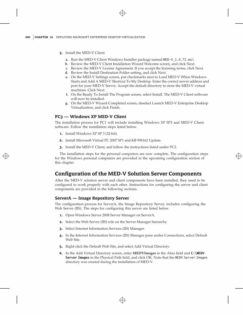
3. Install the MED-V Client.
a. Run the MED-V Client Windows Installer package named MED-V_1.0.72.msi.b. Review the MED-V Client Installation Wizard Welcome screen, and click Next.c. Review the MED-V License Agreement. If you accept the licensing terms, click Next.d. Review the Install Destination Folder setting, and click Next.e. On the MED-V Settings screen, put checkmarks next to Load MED-V When Windows
Starts and Add A MED-V Shortcut To My Desktop. Enter the correct server address andport for your MED-V Server. Accept the default directory to store the MED-V virtualmachines. Click Next.
f. On the Ready To Install The Program screen, select Install. The MED-V Client softwarewill now be installed.
g. On the MED-V Wizard Completed screen, deselect Launch MED-V Enterprise DesktopVirtualization, and click Finish.
PC3 — Windows XP MED-V ClientThe installation process for PC1 will include installing Windows XP SP3 and MED-V Clientsoftware. Follow the installation steps listed below.
1. Install Windows XP SP 3 (32-bit).
2. Install Microsoft Virtual PC 2007 SP1 and KB 958162 Update.
3. Install the MED-V Client, and follow the instructions listed under PC2.
The installation steps for the personal computers are now complete. The configuration stepsfor the Windows personal computers are provided in the upcoming configuration section ofthis chapter.
Configuration of the MED-V Solution Server ComponentsAfter the MED-V solution server and client components have been installed, they need to beconfigured to work properly with each other. Instructions for configuring the server and clientcomponents are provided in the following sections.
ServerA — Image Repository ServerThe configuration process for ServerA, the Image Repository Server, includes configuring theWeb Server (IIS). The steps for configuring this server are listed below.
1. Open Windows Server 2008 Server Manager on ServerA.
2. Select the Web Server (IIS) role on the Server Manager hierarchy.
3. Select Internet Information Services (IIS) Manager.
4. In the Internet Information Services (IIS) Manager pane under Connections, select DefaultWeb Site.
5. Right-click the Default Web Site, and select Add Virtual Directory.
6. In the Add Virtual Directory screen, enter MEDVImages in the Alias field and C:\MEDVServer Images in the Physical Path field, and click OK. Note that the MEDV Server Imagesdirectory was created during the installation of MED-V.
CONFIGURATION OF THE MED-V SOLUTION SERVER COMPONENTS 491
7. Under Default Web Site, select the MEDVImages folder. In the MEDV Images Home pane,scroll down to the IIS section and select MIME Types � Open Feature from the Actionspane. The following steps will add the MED-V required filename extensions and MIMEtypes:
a. Select Add from the Actions pane. On the Add MIME Type window, enter .ckm in theFile Name Extension field and application/octet-stream in the MIME Type field. ClickOK.
b. Select Add from the Actions pane. On the Add MIME Type window, enter .index inthe File Name Extension field and application/octet-stream in the MIME Type field.Click OK.
8. Under Default Web Site, select the MEDVImages folder. In the MEDV Images Homepane, scroll down to the Other section and select BITS Upload � Open Feature from theActions pane. Select the check box Allow Clients To Upload Files. Select Apply fromthe Actions pane.
9. Under Default Web Site, select the MEDVImages folder. In the Actions pane, select EditPermissions. On the MED-V Server Images Properties screen, choose the Security tab.Select Edit, add the appropriate groups, and select Allow Read Permissions. In thisinstance we will use the group Everyone.
ServerB — Database ServerThe configuration process for ServerB, the Database Server, was conducted during the time ofthe installation. Other database settings related to this server are located in the MED-V ServerConfiguration Manager.
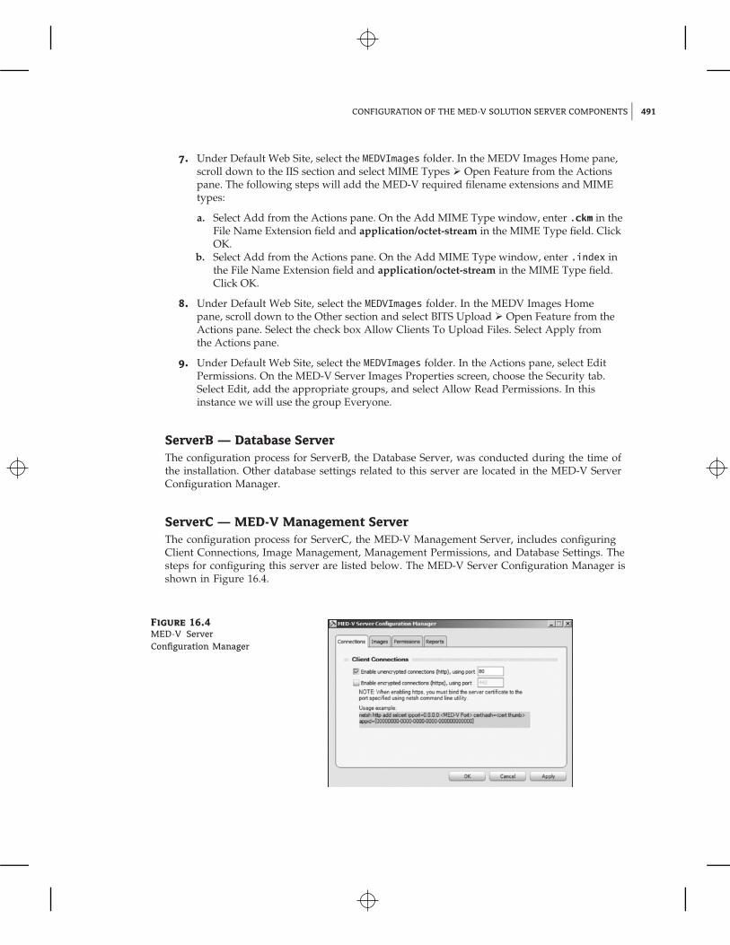
ServerC — MED-V Management ServerThe configuration process for ServerC, the MED-V Management Server, includes configuringClient Connections, Image Management, Management Permissions, and Database Settings. Thesteps for configuring this server are listed below. The MED-V Server Configuration Manager isshown in Figure 16.4.
Figure 16.4
MED-V ServerConfiguration Manager
492 CHAPTER 16 DEPLOYING MICROSOFT ENTERPRISE DESKTOP VIRTUALIZATION
1. Open MED-V Server Configuration Manager from the Start menu on ServerC.
2. The Connections Tab will be selected by default.
a. Select the type of connection. MED-V Server provides two types of connections options:unencrypted connections using port 80 and encrypted connections using port 443. Inthis instance we will use the default setting, Enable Unencrypted Connections (http),Using Port 80.
3. Select the Images tab.
a. Enter the VMs Directory location. In this instance we will use the default directory loca-tion, C:\MED-V Server Images\. Earlier we configured the Web Server (IIS) to use thesame directory.
b. Enter the VMs URL In this instance the URL is http://ServerC/medvimages.
4. Select the Permissions tab.
a. Add the preferred domain users or groups who will need permissions to manage theMED-V Management Server. If the group Everyone has been added by default, removeit by selecting the group and clicking Remove.
5. Select the Reports tab.
a. Select the Enable Reports check box.b. Enter the appropriate value in the Database Server Connection String field. In this
instance the connection string would be DataSource=ServerB\SQLEXPRESS;InitialCatalog=MEDV;UID=SA;PWD=P@ssword1. A complex password was used to meet theWindows Server password policy requirement.
c. Click the Create Database button. Click the Test Connection button.
6. Click the OK button. When prompted to restart the MED-V Management Server, click Yes.
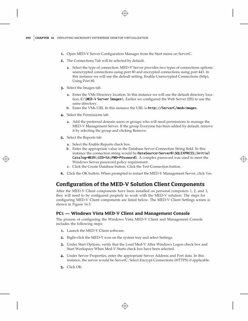
Configuration of the MED-V Solution Client ComponentsAfter the MED-V Client components have been installed on personal computers 1, 2, and 3,they will need to be configured properly to work with the MED-V solution. The steps forconfiguring MED-V Client components are listed below. The MED-V Client Settings screen isshown in Figure 16.5.
PC1 — Windows Vista MED-V Client and Management ConsoleThe process of configuring the Windows Vista MED-V Client and Management Consoleincludes the following steps:
1. Launch the MED-V Client software.
2. Right-click the MED-V icon on the system tray and select Settings.
3. Under Start Options, verify that the Load Med-V After Windows Logon check box andStart Workspace When Med-V Starts check box have been selected.
4. Under Server Properties, enter the appropriate Server Address and Port data. In thisinstance, the server would be ServerC. Select Encrypt Connections (HTTPS) if applicable.
5. Click OK.
PREPARING, DEPLOYING, AND UPDATING MED-V IMAGES AND WORKSPACES 493
Figure 16.5
MED-V Client settings
PC2 — Windows Vista MED-V ClientThe steps for configuring the Windows Vista MED-V Client are the same as those performedon PC1. Please refer to the MED-V Client configuration instructions for PC1.
PC3 — Windows XP MED-V ClientThe steps for configuring the Windows XP MED-V Client are the same as those performed onPC1. Please refer to the MED-V Client configuration instructions for PC1.
Preparing, Deploying, and Updating MED-V Images andWorkspacesNow that the MED-V solution components have been installed and configured on the requiredservers and clients, the environment is ready to create and prepare VPC images, create testMED-V Workspace images, and deploy MED-V workspace images. The following sections pro-vide an overview of this process.
Create and Prepare a VPC Image for MED-VA MED-V Workspace image consists of a Virtual PC (VPC) virtual machine that has been prop-erly prepared for the MED-V environment. The preparation consists of the following steps:
1. Create the virtual machine image with the Microsoft Virtual PC Console. As mentionedbefore, Microsoft Virtual PC 2007 SP1 with KB 958162 update is required. In thisinstance, we will use VM configuration settings of 512 MB memory and hard disk size of65 GB.
2. Start the new virtual machine and install Windows XP SP2/SP3 or Windows 2000 SP4 inthe VPC virtual machine. Note that the MED-V solution requires this Windows client oper-ating system to use a Volume License Key (VLK).
494 CHAPTER 16 DEPLOYING MICROSOFT ENTERPRISE DESKTOP VIRTUALIZATION
3. Install the VPC Virtual Machine Additions on the virtual machine.
a. On the Virtual PC VM Console menu, select Action � Install Or Update VirtualMachine Additions.
b. On the Would You Like To Install Or Update The Virtual Machine Additions Now?window, click Continue.
c. On the Welcome To Setup For Virtual Machine Additions window, click Next, and theinstallation process will begin.
d. On the Setup Completed window, click Finish and Yes to restart Windows.
4. Install Microsoft .NET Framework 2.0 SP1 on the virtual machine. Microsoft .NET Frame-work 2.0 SP 1 can be downloaded from www.microsoft.com/downloads.
5. Install any additional software, such as utilities and applications.
6. Install MED-V Workspace software, and run the VM Prerequisites tool on the virtualmachine.
a. Run the MED-V installation file MED-V_Workspace_1.0.72.msi in the virtual machine.b. On the Welcome To The InstallShield Wizard For MED-V screen, click Next.c. Review the License Agreement screen, and if you accept the terms, select I Accept The
Terms In The Agreement, and click Next.d. On the Ready To Install Program screen, click Install.e. On the InstallShield Wizard Completed screen, select the check box for launching the
VM Prerequisites tool and click Finish. Note that you can also run this tool from Start� All Programs � MED-V � MED-V VM Prerequisites Wizard.
f. Review the MED-V VM Prerequisite Wizard Welcome screen, and click Next.g. Review the Windows Settings screen, accept the default settings, and click Next.h. Review the Internet Explorer screen, accept the default settings, and click Next.i. Review the Windows Services screen, accept the default settings, and click Next.j. On the Windows Auto Logon screen, select the check box for Enable Windows Auto
Logon, enter a valid username and password, and click Apply.k. On the MED-V pop-up screen, when asked if you want to apply all the changes now,
click Yes.
7. Review the Summary screen, and click Finish.
8. Test the newly created VPC image to ensure that the virtual machine, Windows operatingsystem, and applications are running properly.
9. The next step is to run the System Preparation Utility (Sysprep) on the Windows operatingsystem. In this instance we will follow the steps below. For more information on how to useSysprep, please refer to technet.microsoft.com.
a. Create a directory called Sysprep on the root directory of the Windows XP VM.b. From the Windows XP media or www.microsoft.com/downloads, copy the Deploy
Cabinet file to the VM. This file is located on the Windows XP media in the\support\tools directory.
c. Extract the setupmgr, sysprep, and setupcl files from to the sysprep directory.d. Run the extracted setupmgr (Microsoft Setup Manager Wizard) file. Follow the Setup
Manager Wizard, and create a new answer file, choose Sysprep setup, choose the cor-rect product version, accept the terms of the licensing agreement (only if you agree to
PREPARING, DEPLOYING, AND UPDATING MED-V IMAGES AND WORKSPACES 495
them), enter the name and organization, accept the default display settings, enter thetime zone, enter the Volume Licensing Key (VLK) product key, select to auto generatethe computer name, enter an administrator password, select network components, enterthe workgroup or domain, enter Telephony settings, enter Regional settings, select alanguage, install printers, and enter additional commands and an identification string ifappropriate. Click Finish, and save the answer file by clicking OK. Once Setup Manageris complete, close the Completing Setup Manager window.
e. Run the extracted sysprep file. Follow the Sysprep wizard, clicking OK to run Sysprep,selecting to use Mini-Setup, and clicking the Reseal button. Click OK to regenerate SIDs.The Sysprep process will begin and when completed will shut down Windows and stopthe VM.
Creating a MED-V ImageAfter the VPC virtual machine has been created and prepared for the MED-V environment,you can upload it into the Image Repository. The process for creating a test image, packing thetested image, and uploading or extracting the image is described next.
The first step to adding our newly created VPC virtual machine into the MED-V environ-ment is to create a test image. The steps for creating a test image are as follows:
Creating a Test Image
1. From PC1 client launch the MED-V Management Console from Start � All Programs� MED-V � MED-V Management or from the MED-V Management desktop shortcut.
2. Select the Images icon.
3. Under Local Test Images, select New.
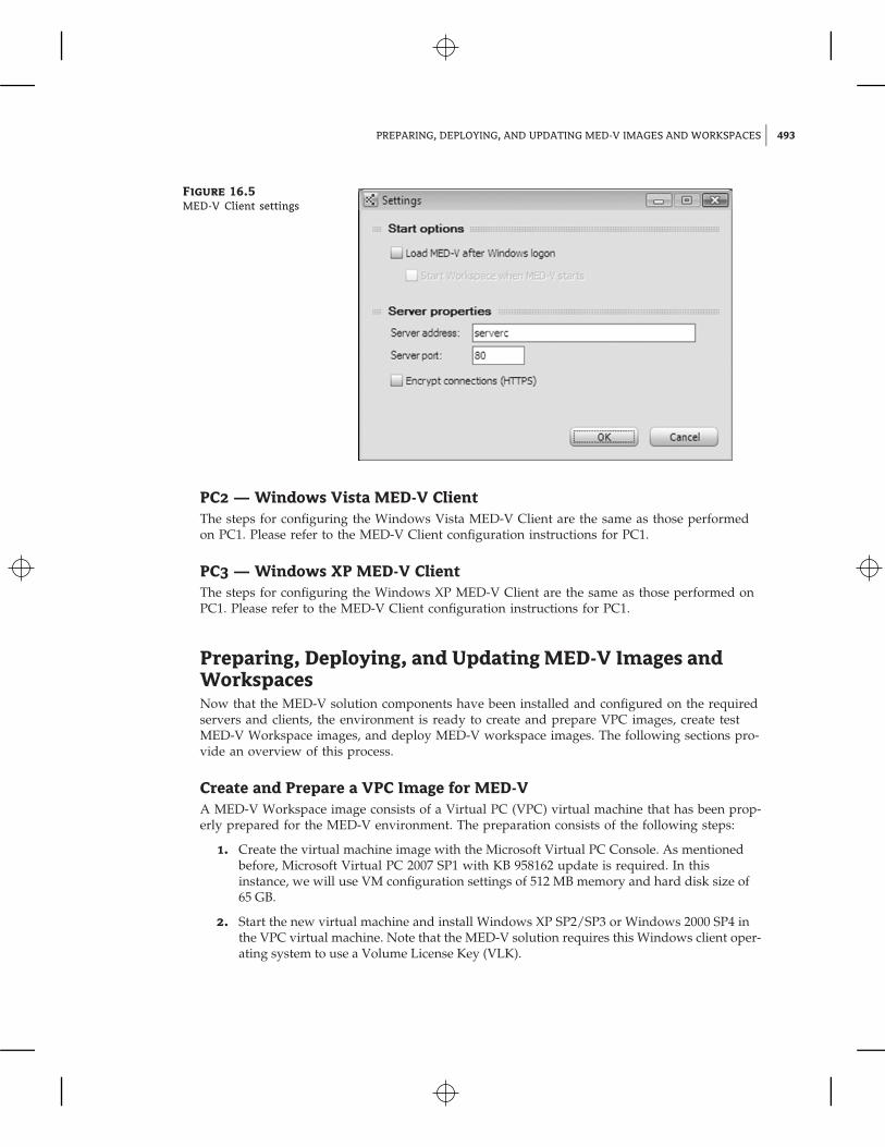
4. On the Test Image Creation dialog box, click Browse, select the Windows VM Settings filefor the Windows XP image we just created, and click Open. Enter an image name and clickOK. The Image Creation dialog box is shown in Figure 16.6. The process will create a newdirectory on the Management Console’s local hard disk at C:\MED-V_Images\imagename.The directory includes a GlobalImageData XML file and Test directory. The Test direc-tory includes an ImageState XML file and the image’s Virtual Machine Settings file.
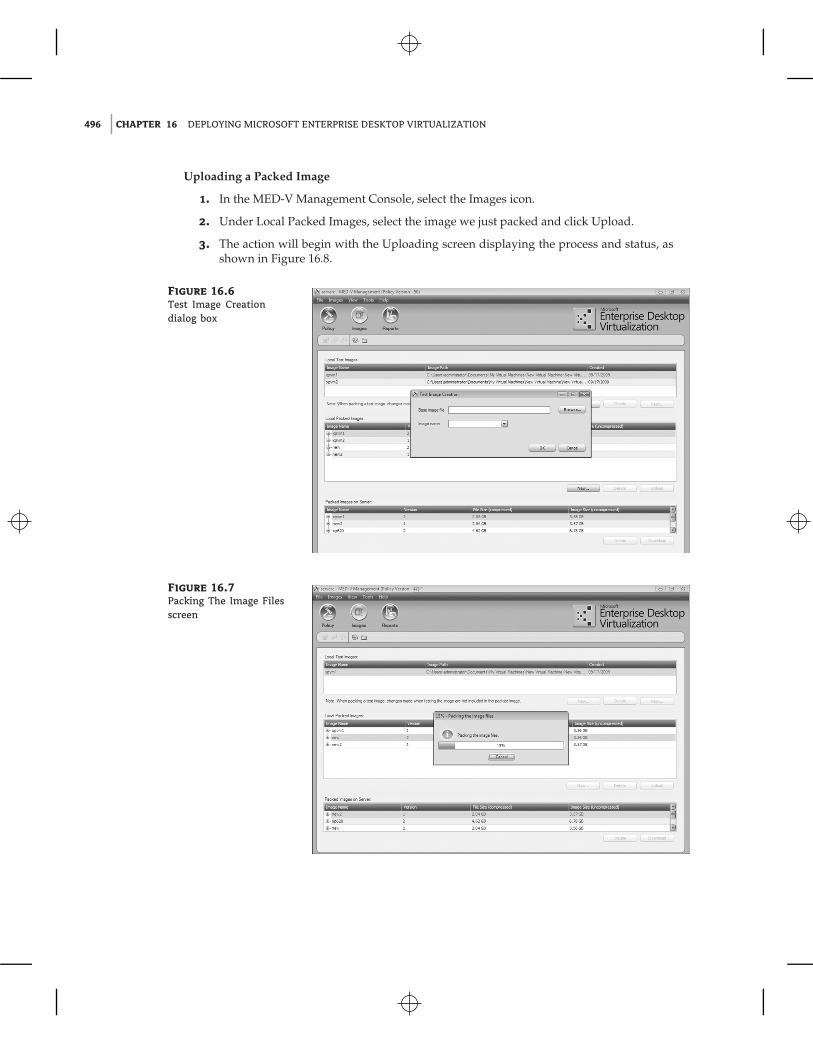
After a test image has been created and tested, you can further prepare the image by pack-ing it. The packing process compresses the image and stores it on the Management Console’slocal hard disk at C:\MED-V_Images\PackedImages. Two packed image files are created: theKidaro Compressed Machine (imagename.ckm) file and the Index file (imagename.ckm.index)file.
Packing an Image
1. In the MED-V Management Console, select the Images icon.
2. Under Local Test Images, select the test image we created earlier and click Pack.
The packing process will begin with the Packing The Image Files screen displayingthe process and status, as shown in Figure 16.7. This process may take several minutes tocomplete.
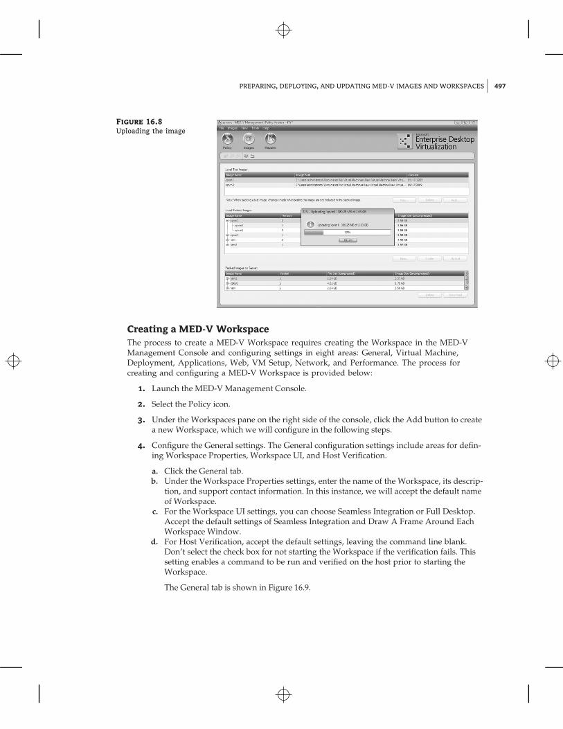
Once a MED-V image has been packed, it can be uploaded. The uploading process copiesthe packed image files to the Repository Server, where it is available for client deployments.
496 CHAPTER 16 DEPLOYING MICROSOFT ENTERPRISE DESKTOP VIRTUALIZATION
Uploading a Packed Image
1. In the MED-V Management Console, select the Images icon.
2. Under Local Packed Images, select the image we just packed and click Upload.
3. The action will begin with the Uploading screen displaying the process and status, asshown in Figure 16.8.
Figure 16.6
Test Image Creationdialog box
Figure 16.7
Packing The Image Filesscreen
PREPARING, DEPLOYING, AND UPDATING MED-V IMAGES AND WORKSPACES 497
Figure 16.8
Uploading the image
Creating a MED-V WorkspaceThe process to create a MED-V Workspace requires creating the Workspace in the MED-VManagement Console and configuring settings in eight areas: General, Virtual Machine,Deployment, Applications, Web, VM Setup, Network, and Performance. The process forcreating and configuring a MED-V Workspace is provided below:
1. Launch the MED-V Management Console.
2. Select the Policy icon.
3. Under the Workspaces pane on the right side of the console, click the Add button to createa new Workspace, which we will configure in the following steps.
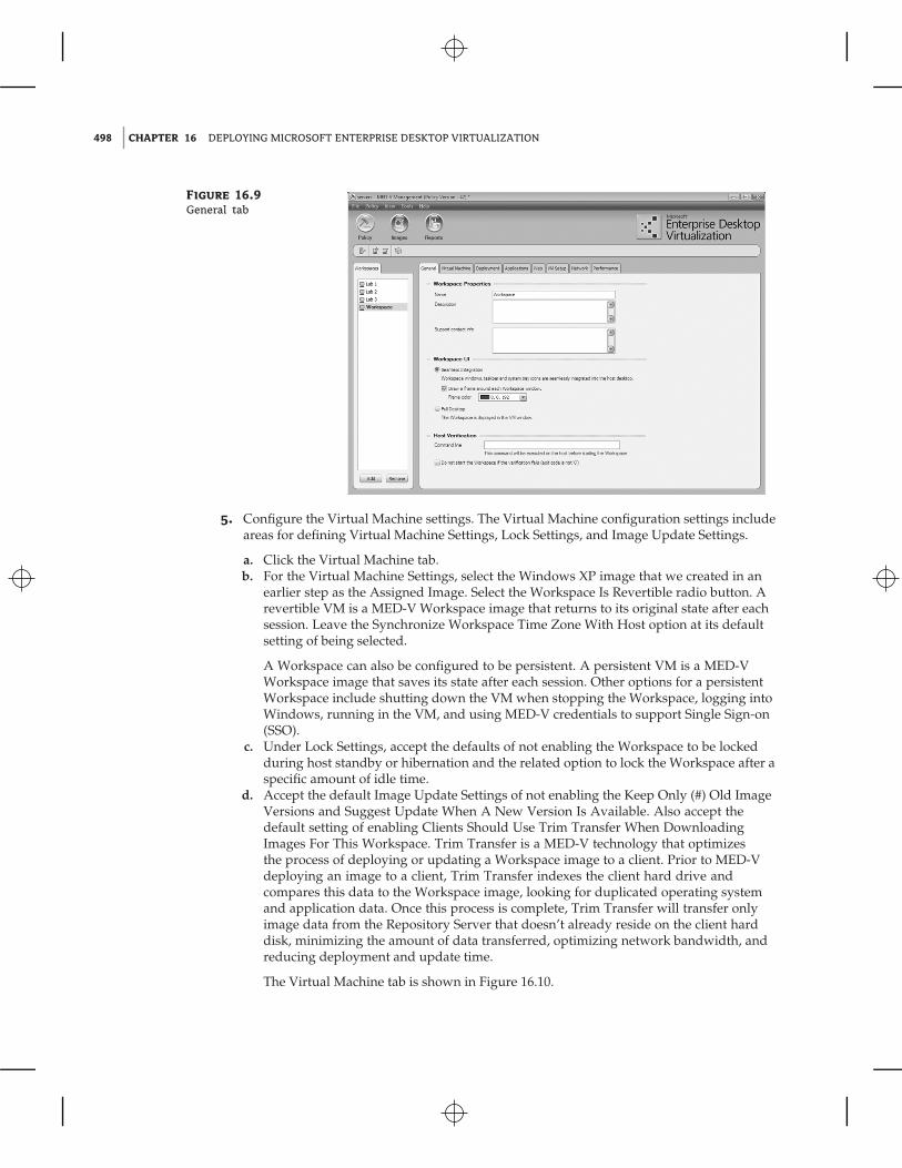
4. Configure the General settings. The General configuration settings include areas for defin-ing Workspace Properties, Workspace UI, and Host Verification.
a. Click the General tab.b. Under the Workspace Properties settings, enter the name of the Workspace, its descrip-
tion, and support contact information. In this instance, we will accept the default nameof Workspace.
c. For the Workspace UI settings, you can choose Seamless Integration or Full Desktop.Accept the default settings of Seamless Integration and Draw A Frame Around EachWorkspace Window.
d. For Host Verification, accept the default settings, leaving the command line blank.Don’t select the check box for not starting the Workspace if the verification fails. Thissetting enables a command to be run and verified on the host prior to starting theWorkspace.
The General tab is shown in Figure 16.9.
498 CHAPTER 16 DEPLOYING MICROSOFT ENTERPRISE DESKTOP VIRTUALIZATION
Figure 16.9
General tab
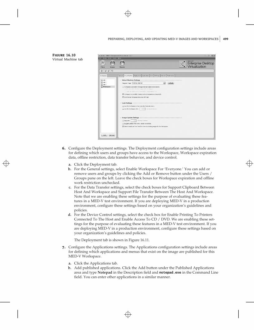
5. Configure the Virtual Machine settings. The Virtual Machine configuration settings includeareas for defining Virtual Machine Settings, Lock Settings, and Image Update Settings.
a. Click the Virtual Machine tab.b. For the Virtual Machine Settings, select the Windows XP image that we created in an
earlier step as the Assigned Image. Select the Workspace Is Revertible radio button. Arevertible VM is a MED-V Workspace image that returns to its original state after eachsession. Leave the Synchronize Workspace Time Zone With Host option at its defaultsetting of being selected.
A Workspace can also be configured to be persistent. A persistent VM is a MED-VWorkspace image that saves its state after each session. Other options for a persistentWorkspace include shutting down the VM when stopping the Workspace, logging intoWindows, running in the VM, and using MED-V credentials to support Single Sign-on(SSO).
c. Under Lock Settings, accept the defaults of not enabling the Workspace to be lockedduring host standby or hibernation and the related option to lock the Workspace after aspecific amount of idle time.
d. Accept the default Image Update Settings of not enabling the Keep Only (#) Old ImageVersions and Suggest Update When A New Version Is Available. Also accept thedefault setting of enabling Clients Should Use Trim Transfer When DownloadingImages For This Workspace. Trim Transfer is a MED-V technology that optimizesthe process of deploying or updating a Workspace image to a client. Prior to MED-Vdeploying an image to a client, Trim Transfer indexes the client hard drive andcompares this data to the Workspace image, looking for duplicated operating systemand application data. Once this process is complete, Trim Transfer will transfer onlyimage data from the Repository Server that doesn’t already reside on the client harddisk, minimizing the amount of data transferred, optimizing network bandwidth, andreducing deployment and update time.
The Virtual Machine tab is shown in Figure 16.10.
PREPARING, DEPLOYING, AND UPDATING MED-V IMAGES AND WORKSPACES 499
Figure 16.10
Virtual Machine tab
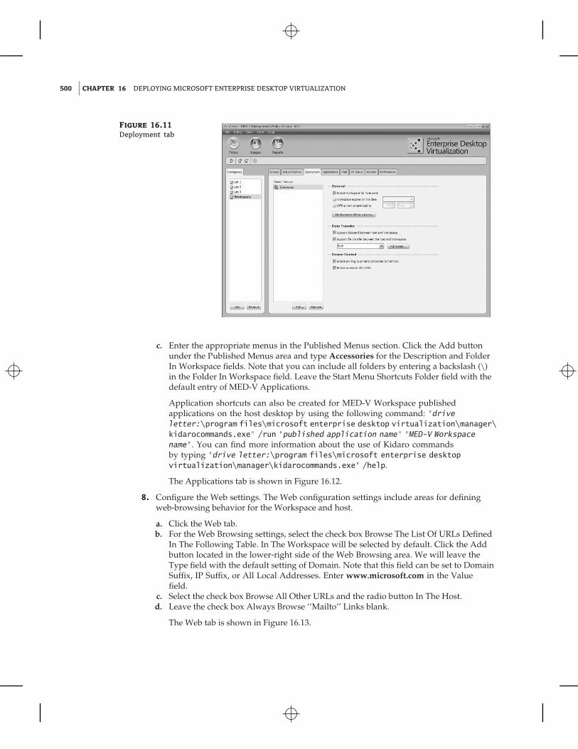
6. Configure the Deployment settings. The Deployment configuration settings include areasfor defining which users and groups have access to the Workspace, Workspace expirationdata, offline restriction, data transfer behavior, and device control.
a. Click the Deployment tab.b. For the General settings, select Enable Workspace For ‘Everyone.’ You can add or
remove users and groups by clicking the Add or Remove button under the Users /Groups pane on the left. Leave the check boxes for Workspace expiration and offlinework restriction unchecked.
c. For the Data Transfer settings, select the check boxes for Support Clipboard BetweenHost And Workspace and Support File Transfer Between The Host And Workspace.Note that we are enabling these settings for the purpose of evaluating these fea-tures in a MED-V test environment. If you are deploying MED-V in a productionenvironment, configure these settings based on your organization’s guidelines andpolicies.
d. For the Device Control settings, select the check box for Enable Printing To PrintersConnected To The Host and Enable Access To CD / DVD. We are enabling these set-tings for the purpose of evaluating these features in a MED-V test environment. If youare deploying MED-V in a production environment, configure these settings based onyour organization’s guidelines and policies.
The Deployment tab is shown in Figure 16.11.
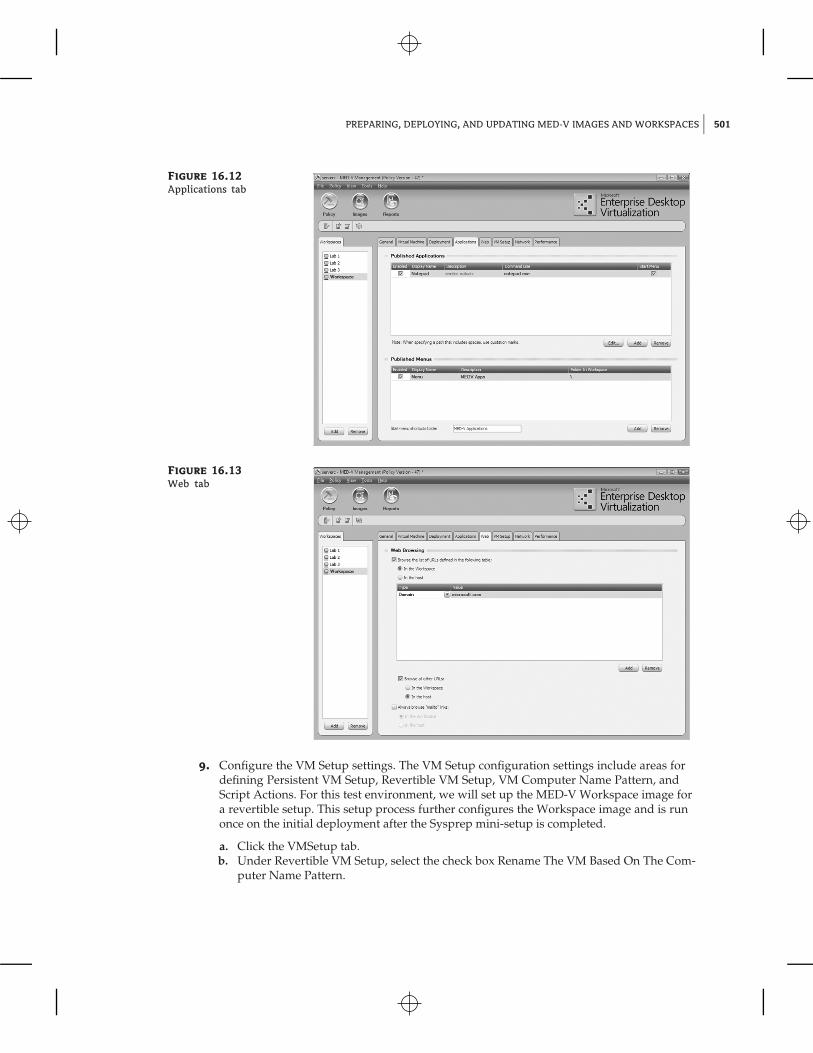
7. Configure the Applications settings. The Applications configuration settings include areasfor defining which applications and menus that exist on the image are published for thisMED-V Workspace.
a. Click the Applications tab.b. Add published applications. Click the Add button under the Published Applications
area and type Notepad in the Description field and notepad.exe in the Command Linefield. You can enter other applications in a similar manner.
500 CHAPTER 16 DEPLOYING MICROSOFT ENTERPRISE DESKTOP VIRTUALIZATION
Figure 16.11
Deployment tab
c. Enter the appropriate menus in the Published Menus section. Click the Add buttonunder the Published Menus area and type Accessories for the Description and FolderIn Workspace fields. Note that you can include all folders by entering a backslash (\)in the Folder In Workspace field. Leave the Start Menu Shortcuts Folder field with thedefault entry of MED-V Applications.
Application shortcuts can also be created for MED-V Workspace publishedapplications on the host desktop by using the following command: "driveletter:\program files\microsoft enterprise desktop virtualization\manager\kidarocommands.exe" /run "published application name" "MED-V Workspacename". You can find more information about the use of Kidaro commandsby typing "drive letter:\program files\microsoft enterprise desktopvirtualization\manager\kidarocommands.exe" /help.
The Applications tab is shown in Figure 16.12.
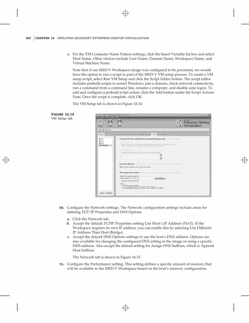
8. Configure the Web settings. The Web configuration settings include areas for definingweb-browsing behavior for the Workspace and host.
a. Click the Web tab.b. For the Web Browsing settings, select the check box Browse The List Of URLs Defined
In The Following Table. In The Workspace will be selected by default. Click the Addbutton located in the lower-right side of the Web Browsing area. We will leave theType field with the default setting of Domain. Note that this field can be set to DomainSuffix, IP Suffix, or All Local Addresses. Enter www.microsoft.com in the Valuefield.
c. Select the check box Browse All Other URLs and the radio button In The Host.d. Leave the check box Always Browse ‘‘Mailto’’ Links blank.
The Web tab is shown in Figure 16.13.
PREPARING, DEPLOYING, AND UPDATING MED-V IMAGES AND WORKSPACES 501
Figure 16.12
Applications tab
Figure 16.13
Web tab
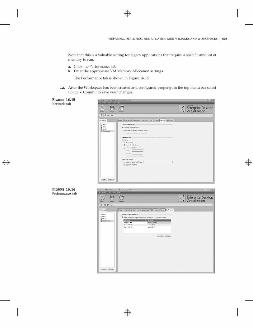
9. Configure the VM Setup settings. The VM Setup configuration settings include areas fordefining Persistent VM Setup, Revertible VM Setup, VM Computer Name Pattern, andScript Actions. For this test environment, we will set up the MED-V Workspace image fora revertible setup. This setup process further configures the Workspace image and is runonce on the initial deployment after the Sysprep mini-setup is completed.
a. Click the VMSetup tab.b. Under Revertible VM Setup, select the check box Rename The VM Based On The Com-
puter Name Pattern.
502 CHAPTER 16 DEPLOYING MICROSOFT ENTERPRISE DESKTOP VIRTUALIZATION
c. For the VM Computer Name Pattern settings, click the Insert Variable list box and selectHost Name. Other choices include User Name, Domain Name, Workspace Name, andVirtual Machine Name.
Note that if our MED-V Workspace image was configured to be persistent, we wouldhave the option to run a script as part of the MED-V VM setup process. To create a VMsetup script, select Run VM Setup and click the Script Editor button. The script editorincludes prebuilt scripts to restart Windows, join a domain, check network connectivity,run a command from a command line, rename a computer, and disable auto logon. Toadd and configure a prebuilt script action, click the Add button under the Script ActionsPane. Once the script is complete, click OK.
The VM Setup tab is shown in Figure 16.14.
Figure 16.14
VM Setup tab
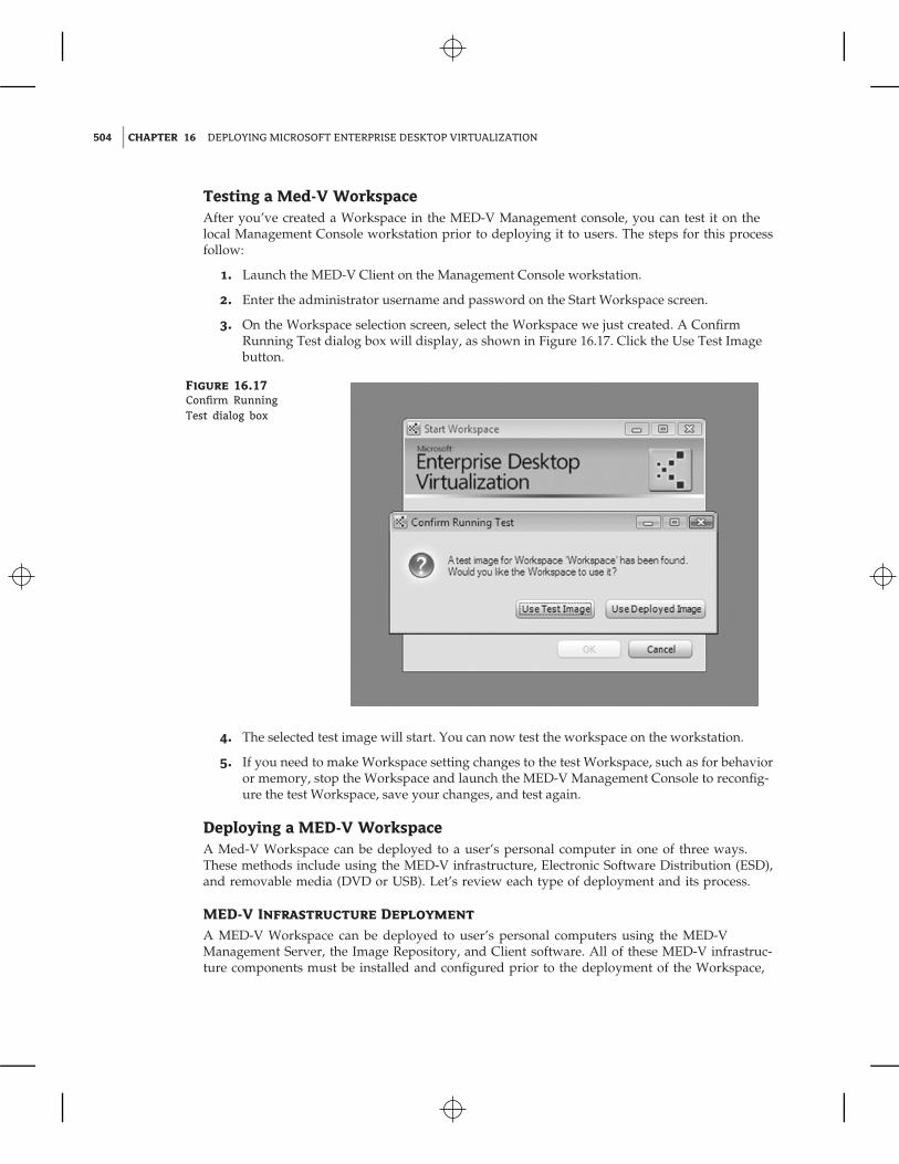
10. Configure the Network settings. The Network configuration settings include areas fordefining TCP/IP Properties and DNS Options.
a. Click the Network tab.b. Accept the default TCPIP Properties setting Use Host’s IP Address (NAT). If the
Workspace requires its own IP address, you can enable this by selecting Use DifferentIP Address Than Host (Bridge).
c. Accept the default DNS Options settings to use the host’s DNS address. Options arealso available for changing the configured DNS setting in the image or using a specificDNS address. Also accept the default setting for Assign DNS Suffixes, which is AppendHost Suffixes.
The Network tab is shown in Figure 16.15.
11. Configure the Performance setting. This setting defines a specific amount of memory thatwill be available to the MED-V Workspace based on the host’s memory configuration.
PREPARING, DEPLOYING, AND UPDATING MED-V IMAGES AND WORKSPACES 503
Note that this is a valuable setting for legacy applications that require a specific amount ofmemory to run.
a. Click the Performance tab.b. Enter the appropriate VM Memory Allocation settings.
The Performance tab is shown in Figure 16.16.
12. After the Workspace has been created and configured properly, in the top menu bar selectPolicy � Commit to save your changes.
Figure 16.15
Network tab
Figure 16.16
Performance tab
504 CHAPTER 16 DEPLOYING MICROSOFT ENTERPRISE DESKTOP VIRTUALIZATION
Testing a Med-V WorkspaceAfter you’ve created a Workspace in the MED-V Management console, you can test it on thelocal Management Console workstation prior to deploying it to users. The steps for this processfollow:
1. Launch the MED-V Client on the Management Console workstation.
2. Enter the administrator username and password on the Start Workspace screen.
3. On the Workspace selection screen, select the Workspace we just created. A ConfirmRunning Test dialog box will display, as shown in Figure 16.17. Click the Use Test Imagebutton.
Figure 16.17
Confirm RunningTest dialog box
4. The selected test image will start. You can now test the workspace on the workstation.
5. If you need to make Workspace setting changes to the test Workspace, such as for behavioror memory, stop the Workspace and launch the MED-V Management Console to reconfig-ure the test Workspace, save your changes, and test again.
Deploying a MED-V WorkspaceA Med-V Workspace can be deployed to a user’s personal computer in one of three ways.These methods include using the MED-V infrastructure, Electronic Software Distribution (ESD),and removable media (DVD or USB). Let’s review each type of deployment and its process.
MED-V Infrastructure Deployment
A MED-V Workspace can be deployed to user’s personal computers using the MED-VManagement Server, the Image Repository, and Client software. All of these MED-V infrastruc-ture components must be installed and configured prior to the deployment of the Workspace,
PREPARING, DEPLOYING, AND UPDATING MED-V IMAGES AND WORKSPACES 505
including the installation of the MED-V Client software and prerequisite software. The processfor deploying a MED-V Workspace using MED-V Infrastructure is provided in the followingsteps.
1. Create the MED-V Workspace and upload the packed image to the repository using theMED-V Management Console using the steps above.
2. Launch the MED-V Client software on the personal computer targeted for the Workspacedeployment.
3. Provide the appropriate username and password on the Start Workspace screen.
4. If the user has been assigned to more than one Workspace, select the desired Workspacefrom the list. The Workspace Download process screen will display and carry out the fol-lowing steps:
a. Index the local hard disk.b. Download the image.
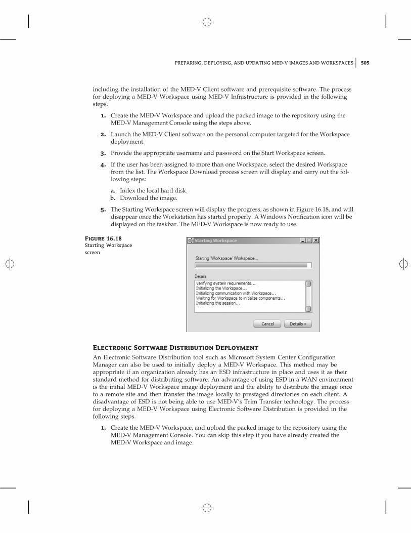
5. The Starting Workspace screen will display the progress, as shown in Figure 16.18, and willdisappear once the Workstation has started properly. A Windows Notification icon will bedisplayed on the taskbar. The MED-V Workspace is now ready to use.
Figure 16.18
Starting Workspacescreen
Electronic Software Distribution Deployment
An Electronic Software Distribution tool such as Microsoft System Center ConfigurationManager can also be used to initially deploy a MED-V Workspace. This method may beappropriate if an organization already has an ESD infrastructure in place and uses it as theirstandard method for distributing software. An advantage of using ESD in a WAN environmentis the initial MED-V Workspace image deployment and the ability to distribute the image onceto a remote site and then transfer the image locally to prestaged directories on each client. Adisadvantage of ESD is not being able to use MED-V’s Trim Transfer technology. The processfor deploying a MED-V Workspace using Electronic Software Distribution is provided in thefollowing steps.
1. Create the MED-V Workspace, and upload the packed image to the repository using theMED-V Management Console. You can skip this step if you have already created theMED-V Workspace and image.
506 CHAPTER 16 DEPLOYING MICROSOFT ENTERPRISE DESKTOP VIRTUALIZATION
2. Download the image to the desired Management Console workstation usingthe MED-V Management Console. The image files will be downloaded to theC:\MED-V_Images\PackedImages\imagename directory on the local hard disk of theManagement Console. You can skip this step if you have already downloaded the MED-VWorkspace and image.
3. Create an Electronic Software Distribution package that includes the two MED-V packedimage files (Compressed Machine file and Index file) that were downloaded.
4. Distribute the packed image files to the targeted user’s personal computer’s hard disk inthe prestaged images directory located at C:\Med-V Images\PrestagedImages.
5. Launch the MED-V Client software on the personal computer targeted for the Workspacedeployment.
6. Provide the appropriate username and password on the Start Workspace screen.
7. If the user has more than one Workspace assigned, choose the desired Workspace.
8. The Starting Workspace screen will display the progress and disappear once the Worksta-tion has started properly. A Windows Notification icon will be displayed on the taskbar.The MED-V Workspace is now ready to use.
Removable Media Deployment
Removable media such as a DVD or USB storage device can also be used to initially deploy aMED-V Workspace. The process for deploying a MED-V Workspace using removable media isprovided in the following steps:
1. Create the MED-V Workspace, and upload the packed image to the repository using theMED-V Management Console. You can skip this step if you have already created theMED-V Workspace and image.
2. Download the image to the desired Management Console workstation using the MED-VManagement Console. The image files will be downloaded to C:\MED-V_Images\PackedImages\imagename directory on the local hard disk of the Management Console.You can skip this step if you have already downloaded the MED-V Workspace andimage.
3. To prepare for the Packaging Wizard deployment package process, create a local ornetwork directory with separate subdirectories for the MED-V client, Virtual PC, and .NETFramework installation files, and copy the associated setup files into these directories.The Packaging Wizard will ask for the location of these installation files during thisprocess.
4. On the MED-V Management Console top menu bar, select Tools � Packaging Wizard.
5. On the Packaging Wizard Deployment Package screen, click Next.
6. On the Workspace Image screen, mark the check box to include the image in the package.Select the image we just downloaded and click Next.
7. On the MED-V Installation Settings screen, select the path where we located the MED-Vinstallation files, enter the MED-V server address and port, select Install MED-V UsingDefault Installation Settings if appropriate, and click Next.
MANAGING THE MED-V SOLUTION 507
8. On the Additional Installations screen, select the appropriate check boxes and installationpath for Virtual PC 2007 SP1, Virtual PC QFE, and .NET Framework 2.0, and click Next.
9. On the Finalize screen, enter the path for the package destination and package name, andclick Finish.
10. Copy the contents of the MED-V deployment package to the removable media (DVD orUSB storage device).
a. On the personal computer targeted for the Workspace deployment, insert the DVD orUSB storage device that has the deployment package files that we previously copied.
b. Open the removable media device, and launch the MedvAutorun.exe application. TheMED-V screen will appear, asking if you would like to install the MED-V package now.The Installer screen will be also be displayed and will provide progress informationfor the installation of Virtual PC 2007 SP1, Virtual PC 2007 SP1 Update, MED-V Client,and the importing of the Workspace image. At the end of the process, the MED-VInstaller window will display a message saying that MED-V was successfully installed.
c. The MED-V Workspace is now ready to use.
Managing the MED-V SolutionThe Microsoft MED-V solution can be managed using Microsoft management tools that areincluded in MED-V, Windows Server 2008, and System Center. The MED-V Management andServer Manager tools are discussed below, along with a mapping of the tools for each serverand client in the solution.
The MED-V solution or instance can be managed by using Server Manager/IIS Manager,MED-V Server Configuration Manager, and MED-V Management Console.
Server Manager, IIS ManagerServer Manager is used to manage the Web Server (IIS) role that supports the MED-V ImageRepository solution. The IIS Main Summary page offers a number of useful tools and informa-tion for managing your MED-V environment. The main page includes System Services, BestPractice Analyzer, Role Services, and Resources And Support. You can access this tool throughServer Manager, by selecting the IIS role or by using IIS Manager.
MED-V Server Configuration ManagerThe MED-V Server Configuration Manager runs on the MED-V Server and is used to initiallyconfigure the MED-V Server environment settings. These settings include client connections,location for storing images in the repository, management permissions, and database settings.If you need to change any of these configuration settings, you would use the MED-V ServerConfiguration Manager tool.
MED-V Management ConsoleThe MED-V Management Console is the primary management tool for the MED-V and sup-ports the life cycle of the Workspace images. It provides management of MED-V Workspaces,images, and reports. The Management tool supports the creation and configuration of MED-VWorkspaces, image creation, and deployment and generation of status, activity, and errorreports.
508 CHAPTER 16 DEPLOYING MICROSOFT ENTERPRISE DESKTOP VIRTUALIZATION
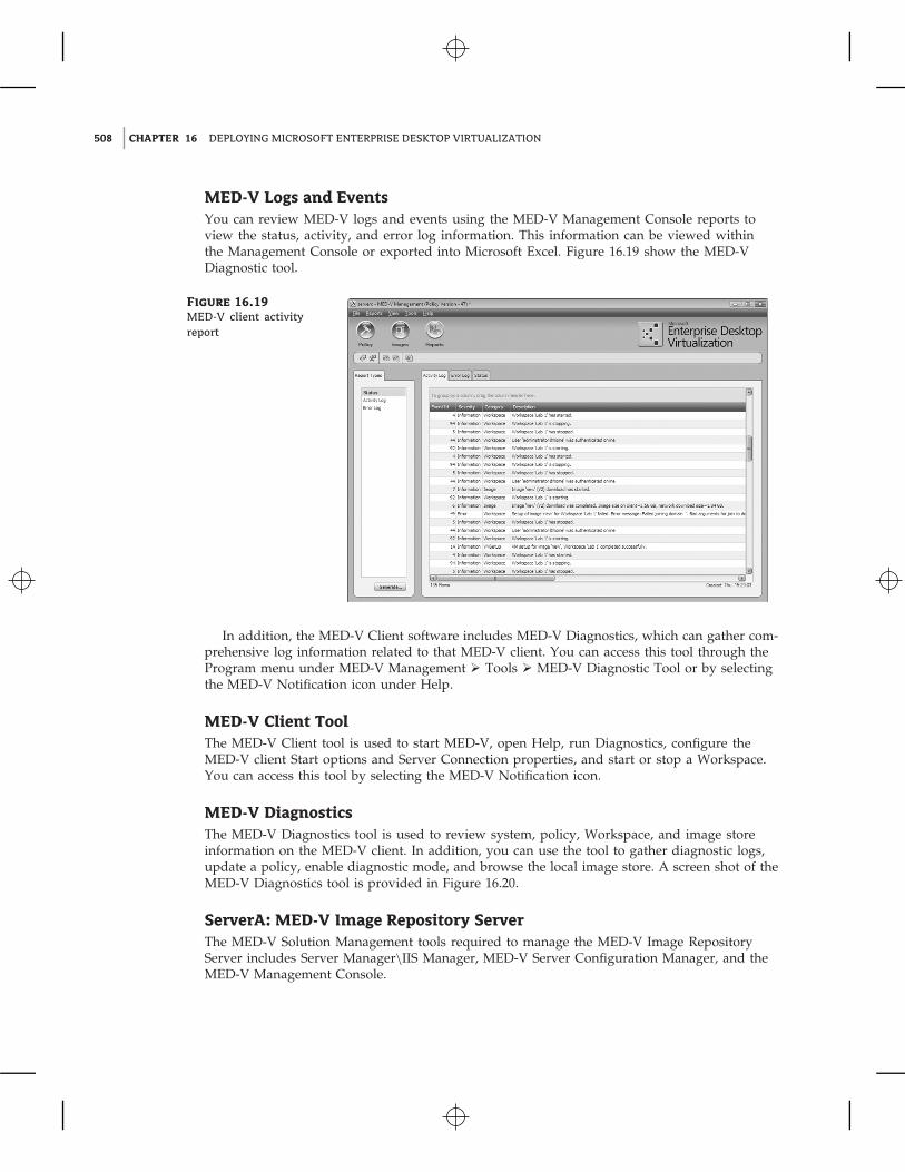
MED-V Logs and EventsYou can review MED-V logs and events using the MED-V Management Console reports toview the status, activity, and error log information. This information can be viewed withinthe Management Console or exported into Microsoft Excel. Figure 16.19 show the MED-VDiagnostic tool.
Figure 16.19
MED-V client activityreport
In addition, the MED-V Client software includes MED-V Diagnostics, which can gather com-prehensive log information related to that MED-V client. You can access this tool through theProgram menu under MED-V Management � Tools � MED-V Diagnostic Tool or by selectingthe MED-V Notification icon under Help.
MED-V Client ToolThe MED-V Client tool is used to start MED-V, open Help, run Diagnostics, configure theMED-V client Start options and Server Connection properties, and start or stop a Workspace.You can access this tool by selecting the MED-V Notification icon.
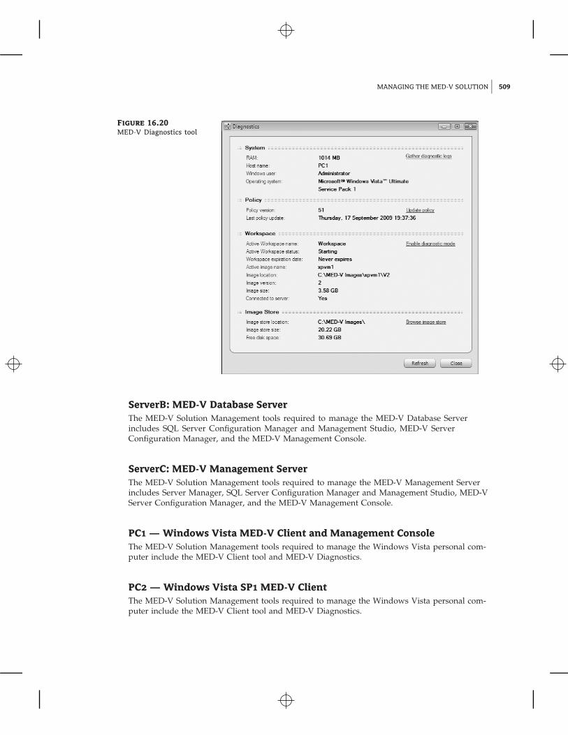
MED-V DiagnosticsThe MED-V Diagnostics tool is used to review system, policy, Workspace, and image storeinformation on the MED-V client. In addition, you can use the tool to gather diagnostic logs,update a policy, enable diagnostic mode, and browse the local image store. A screen shot of theMED-V Diagnostics tool is provided in Figure 16.20.
ServerA: MED-V Image Repository ServerThe MED-V Solution Management tools required to manage the MED-V Image RepositoryServer includes Server Manager\IIS Manager, MED-V Server Configuration Manager, and theMED-V Management Console.
MANAGING THE MED-V SOLUTION 509
Figure 16.20
MED-V Diagnostics tool
ServerB: MED-V Database ServerThe MED-V Solution Management tools required to manage the MED-V Database Serverincludes SQL Server Configuration Manager and Management Studio, MED-V ServerConfiguration Manager, and the MED-V Management Console.
ServerC: MED-V Management ServerThe MED-V Solution Management tools required to manage the MED-V Management Serverincludes Server Manager, SQL Server Configuration Manager and Management Studio, MED-VServer Configuration Manager, and the MED-V Management Console.
PC1 — Windows Vista MED-V Client and Management ConsoleThe MED-V Solution Management tools required to manage the Windows Vista personal com-puter include the MED-V Client tool and MED-V Diagnostics.
PC2 — Windows Vista SP1 MED-V ClientThe MED-V Solution Management tools required to manage the Windows Vista personal com-puter include the MED-V Client tool and MED-V Diagnostics.
510 CHAPTER 16 DEPLOYING MICROSOFT ENTERPRISE DESKTOP VIRTUALIZATION
PC3 — Windows XP SP3 MED-V ClientThe MED-V Solution Management tools required to manage the Windows XP SP3 personalcomputer include the MED-V Client tool and MED-V Diagnostics.
SummaryIn this chapter we reviewed considerations for planning a MED-V deployment, providedguidance for conducting a POC, identified and defined required server and client solutioncomponents, and provided step-by-step instructions for installing, configuring, and deployingMED-V in a test environment.
The Bottom Line
Install and configure the MED-V Management Server. A MED-V solution consists of aManagement Server, Repository Server, Management Console, and Client software.
Master It What Windows operating systems does MED-V support for the host and guests?
Create and prepare a MED-V test image. MED-V uses Microsoft Virtual PC 2007 SP1 to cre-ate its VM images.
Master It How do you prepare a Virtual PC virtual machine for MED-V?
Create and configure a MED-V Workspace image. A MED-V Workspace can be assignedonly one image, but an image can support more than one MED-V Workspace.
Master It Where do you configure the amount of memory that is available to a MED-VWorkspace?
Deploy a MED-V Workspace image. Trim Transfer is a MED-V data transfer technologythat minimizes the amount of data, bandwidth, and time it takes to deploy or update a MED-Vimage to a client.
Master It What are three methods to deploy a MED-V Workspace image to a client?
Generate MED-V reports. MED-V uses Microsoft SQL Server to store reporting data col-lected from MED-V clients.
Master It What tool is used to generate and view MED-V client reports? What types ofreports are available?