75

© 2012 Cisco and/or its affiliates. All rights reserved. BRKDCT-3060 Cisco Public
Deployment Considerations
with Interconnecting Data Centers Patrice Bellagamba
Distinguished SE
Cisco Europe
BRKDCT-3060
© 2012 Cisco and/or its affiliates. All rights reserved. BRKDCT-3060 Cisco Public
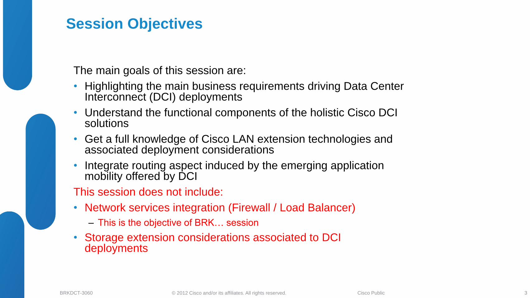
Session Objectives
The main goals of this session are:
• Highlighting the main business requirements driving Data Center Interconnect (DCI) deployments
• Understand the functional components of the holistic Cisco DCI solutions
• Get a full knowledge of Cisco LAN extension technologies and associated deployment considerations
• Integrate routing aspect induced by the emerging application mobility offered by DCI
This session does not include:
• Network services integration (Firewall / Load Balancer)
‒ This is the objective of BRK… session
• Storage extension considerations associated to DCI deployments
3
© 2012 Cisco and/or its affiliates. All rights reserved. BRKDCT-3060 Cisco Public
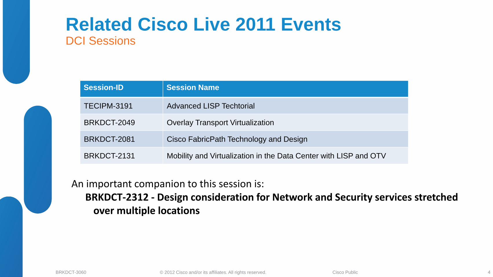
Session-ID Session Name
TECIPM-3191 Advanced LISP Techtorial
BRKDCT-2049 Overlay Transport Virtualization
BRKDCT-2081 Cisco FabricPath Technology and Design
BRKDCT-2131 Mobility and Virtualization in the Data Center with LISP and OTV
Related Cisco Live 2011 Events DCI Sessions
An important companion to this session is: BRKDCT-2312 - Design consideration for Network and Security services stretched
over multiple locations
4
© 2012 Cisco and/or its affiliates. All rights reserved. BRKDCT-3060 Cisco Public
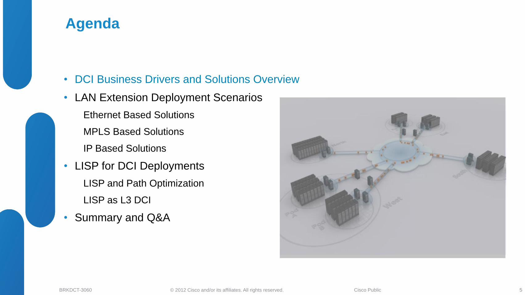
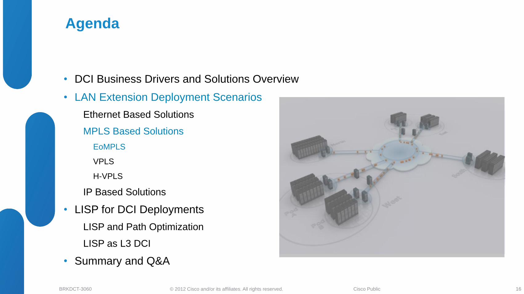
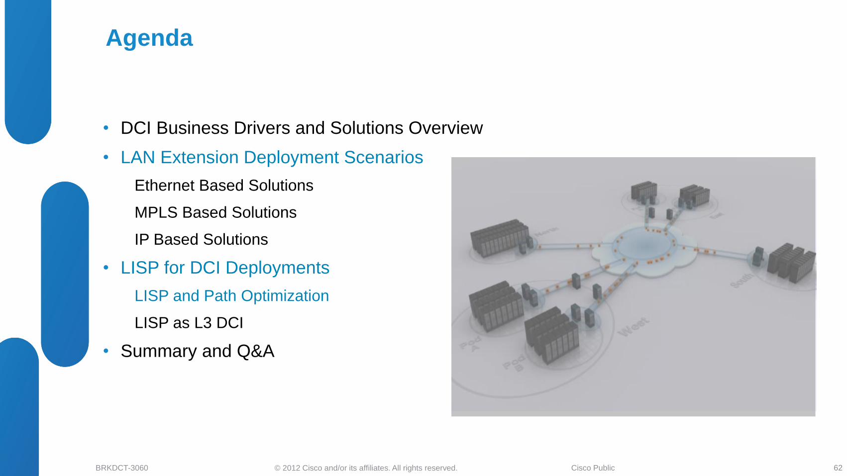
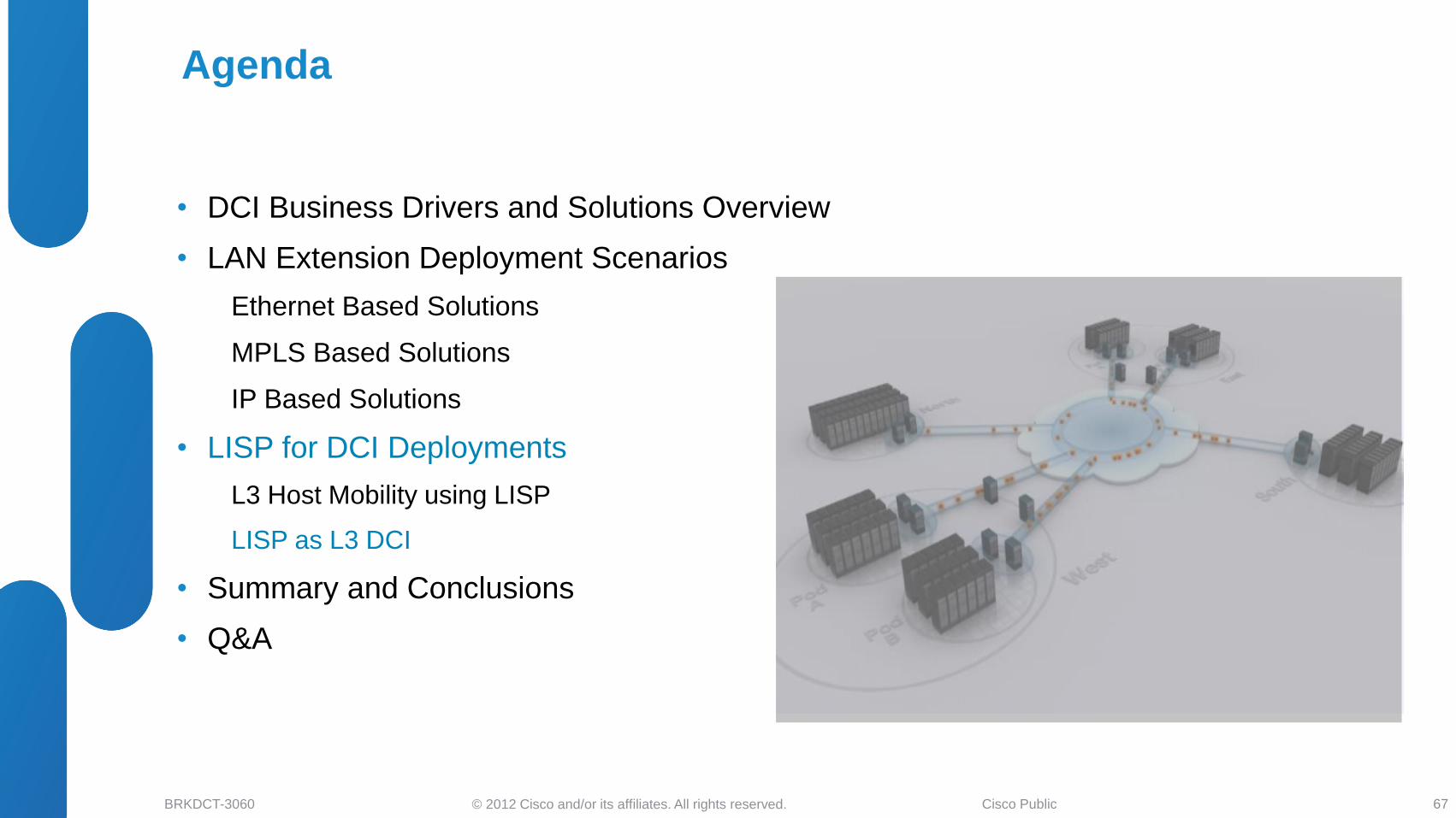
• DCI Business Drivers and Solutions Overview
• LAN Extension Deployment Scenarios
Ethernet Based Solutions
MPLS Based Solutions
IP Based Solutions
• LISP for DCI Deployments
LISP and Path Optimization
LISP as L3 DCI
• Summary and Q&A
Agenda
5
© 2012 Cisco and/or its affiliates. All rights reserved. BRKDCT-3060 Cisco Public
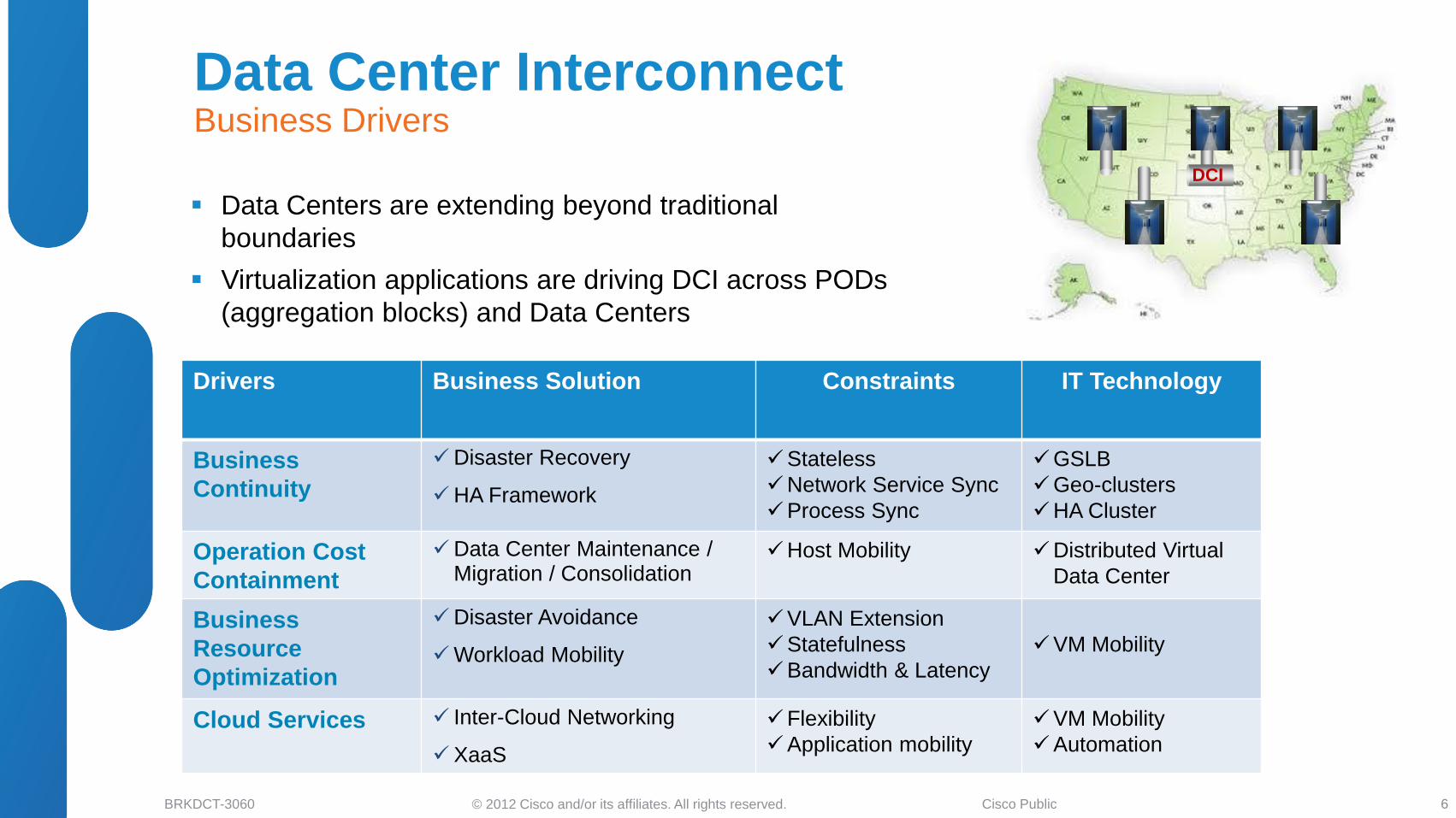
DCI
Drivers Business Solution Constraints IT Technology
Business
Continuity
Disaster Recovery
HA Framework
Stateless
Network Service Sync
Process Sync
GSLB
Geo-clusters
HA Cluster
Operation Cost
Containment
Data Center Maintenance / Migration / Consolidation
Host Mobility Distributed Virtual
Data Center
Business
Resource
Optimization
Disaster Avoidance
Workload Mobility
VLAN Extension
Statefulness
Bandwidth & Latency
VM Mobility
Cloud Services Inter-Cloud Networking
XaaS
Flexibility
Application mobility
VM Mobility
Automation
Data Centers are extending beyond traditional
boundaries
Virtualization applications are driving DCI across PODs
(aggregation blocks) and Data Centers
Data Center Interconnect Business Drivers
6
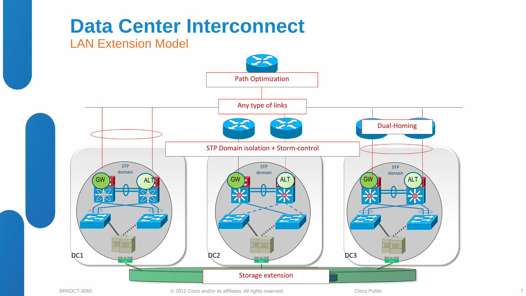
© 2012 Cisco and/or its affiliates. All rights reserved. BRKDCT-3060 Cisco Public 7
DC1 DC2 DC3
STP domain
STP domain
STP domain
SiSiSiSi SiSi SiSi
ALT GW ALT ALT GW GW
Path Optimization
Dual-Homing
Storage extension
Any type of links
STP Domain isolation + Storm-control
Data Center Interconnect LAN Extension Model
© 2012 Cisco and/or its affiliates. All rights reserved. BRKDCT-3060 Cisco Public
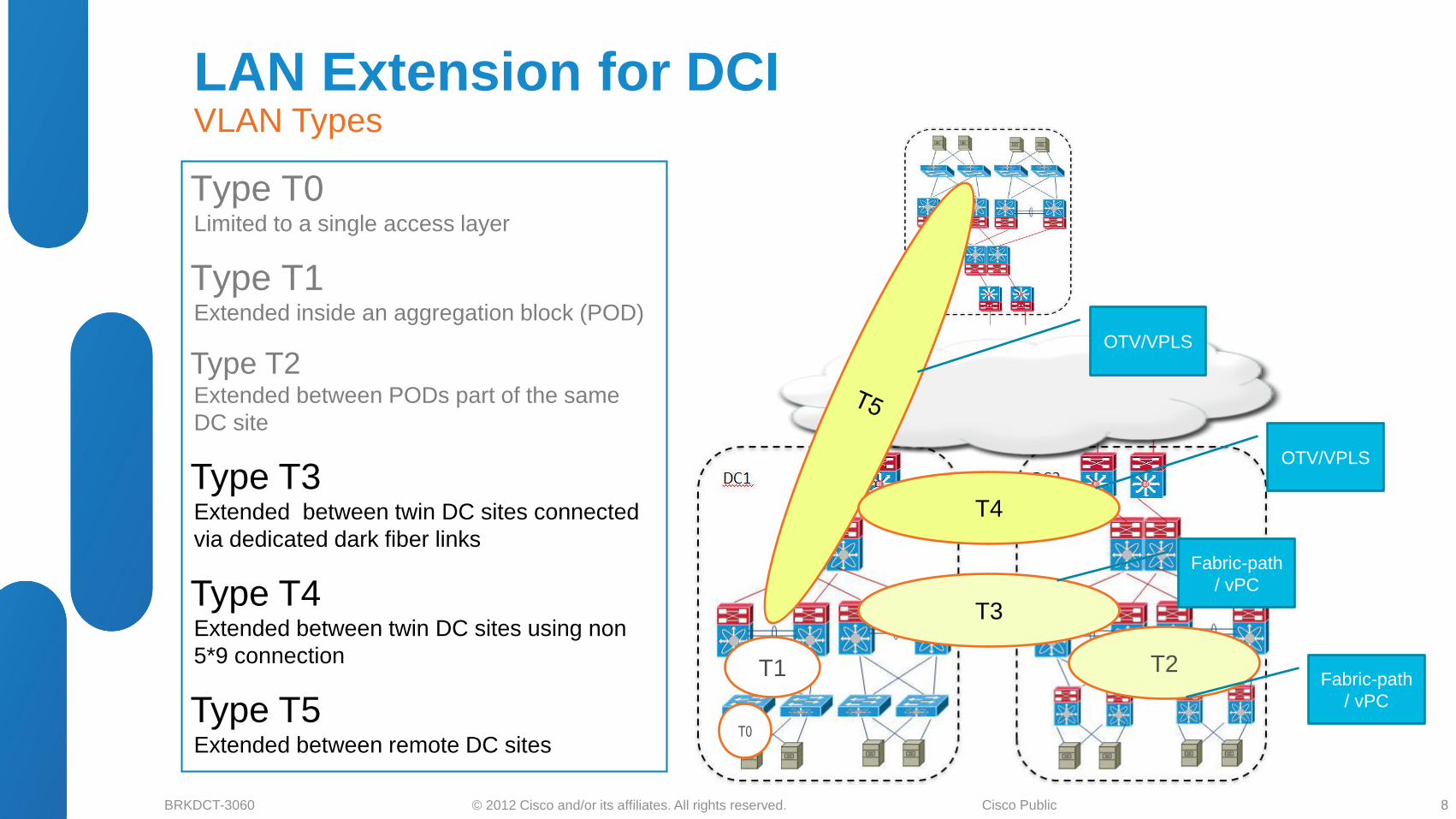
Type T0 Limited to a single access layer
Type T1 Extended inside an aggregation block (POD)
Type T2 Extended between PODs part of the same
DC site
Type T3 Extended between twin DC sites connected
via dedicated dark fiber links
Type T4 Extended between twin DC sites using non
5*9 connection
Type T5 Extended between remote DC sites
T1 T2
T0
T3
T4
Fabric-path
/ vPC
Fabric-path
/ vPC
OTV/VPLS
OTV/VPLS
LAN Extension for DCI VLAN Types
8
© 2012 Cisco and/or its affiliates. All rights reserved. BRKDCT-3060 Cisco Public
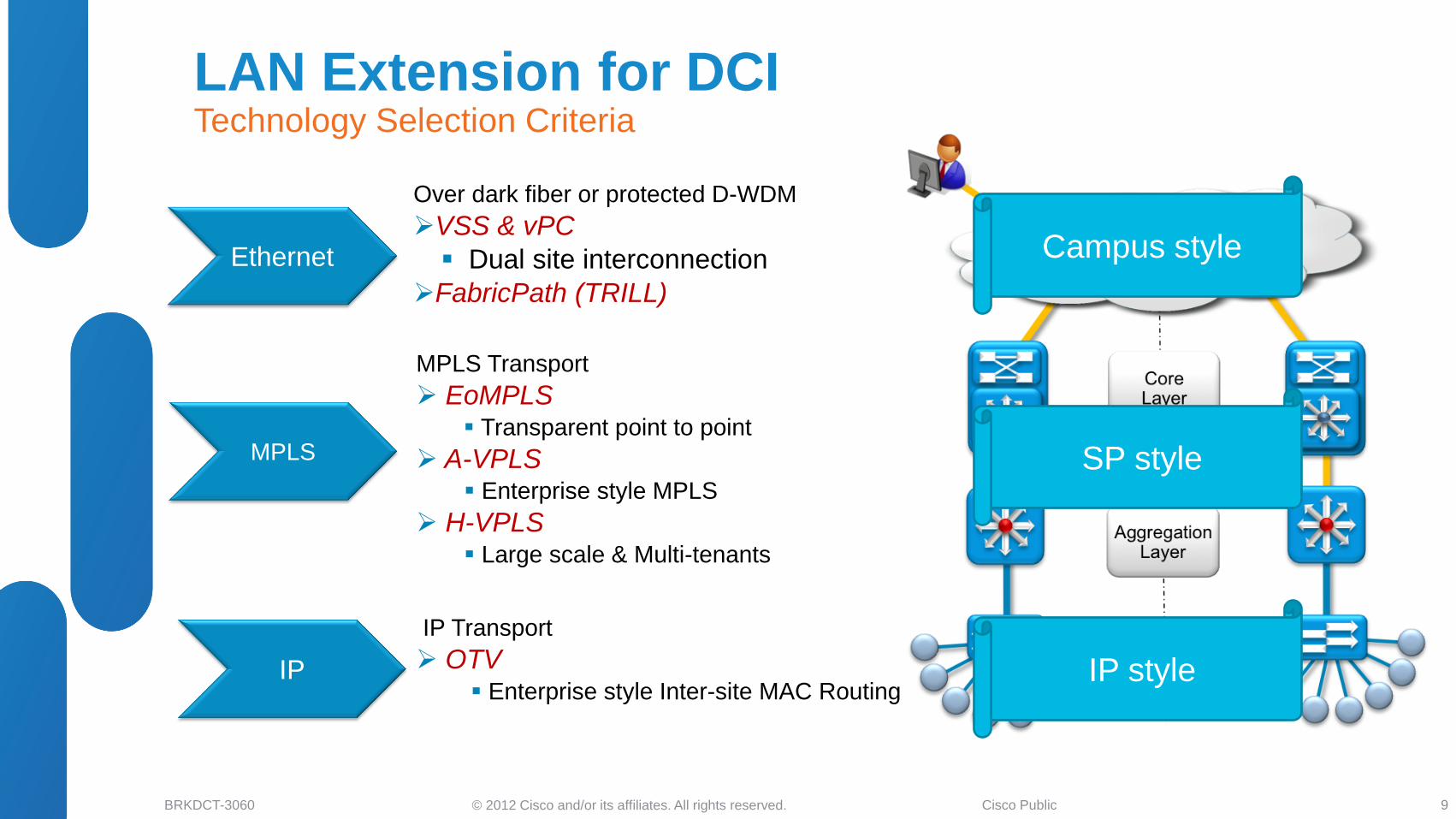
Ethernet
MPLS
IP
Over dark fiber or protected D-WDM
VSS & vPC
Dual site interconnection
FabricPath (TRILL)
MPLS Transport
EoMPLS Transparent point to point
A-VPLS Enterprise style MPLS
H-VPLS Large scale & Multi-tenants
IP Transport
OTV Enterprise style Inter-site MAC Routing
Campus style
SP style
IP style
LAN Extension for DCI Technology Selection Criteria
9
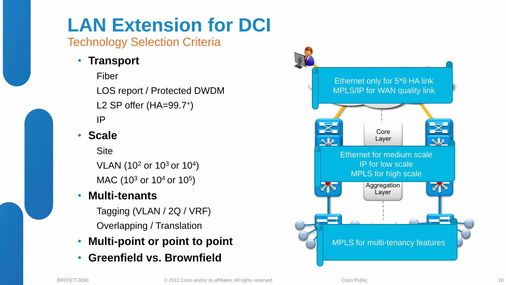
© 2012 Cisco and/or its affiliates. All rights reserved. BRKDCT-3060 Cisco Public
• Transport
Fiber
LOS report / Protected DWDM
L2 SP offer (HA=99.7+)
IP
• Scale
Site
VLAN (102 or 103 or 104)
MAC (103 or 104 or 105)
• Multi-tenants
Tagging (VLAN / 2Q / VRF)
Overlapping / Translation
• Multi-point or point to point
• Greenfield vs. Brownfield
Ethernet only for 5*9 HA link
MPLS/IP for WAN quality link
Ethernet for medium scale
IP for low scale
MPLS for high scale
MPLS for multi-tenancy features
LAN Extension for DCI Technology Selection Criteria
10
© 2012 Cisco and/or its affiliates. All rights reserved. BRKDCT-3060 Cisco Public
• DCI Business Drivers and Solutions Overview
• LAN Extension Deployment Scenarios
Ethernet Based Solutions
VSS, vPC and FabricPath
MPLS Based Solutions
IP Based Solutions
• LISP for DCI Deployments
LISP and Path Optimization
LISP as L3 DCI
• Summary and Q&A
Agenda
11
© 2012 Cisco and/or its affiliates. All rights reserved. BRKDCT-3060 Cisco Public
WAN
L
3
L
3
Server Cabinet Pair 1 Server Cabinet Pair N Server Cabinet Pair 1 Server Cabinet Pair N
L
2
L
2
SiSi SiSi
Primary Root Primary Root
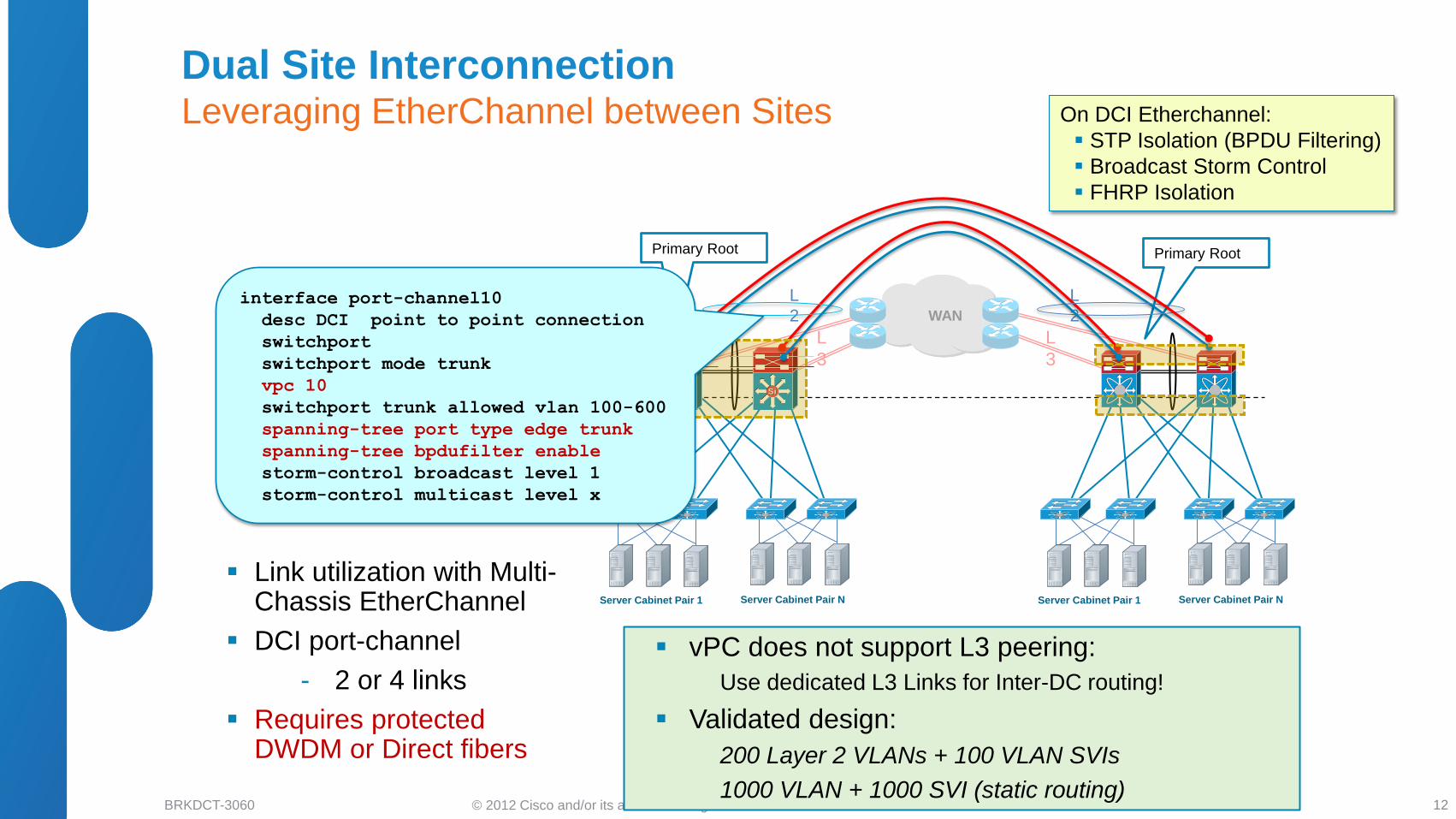
On DCI Etherchannel:
STP Isolation (BPDU Filtering)
Broadcast Storm Control
FHRP Isolation
Link utilization with Multi-Chassis EtherChannel
DCI port-channel
- 2 or 4 links
Requires protected DWDM or Direct fibers
vPC does not support L3 peering:
Use dedicated L3 Links for Inter-DC routing!
Validated design:
200 Layer 2 VLANs + 100 VLAN SVIs
1000 VLAN + 1000 SVI (static routing)
interface port-channel10
desc DCI point to point connection
switchport
switchport mode trunk
vpc 10
switchport trunk allowed vlan 100-600
spanning-tree port type edge trunk
spanning-tree bpdufilter enable
storm-control broadcast level 1
storm-control multicast level x
Dual Site Interconnection Leveraging EtherChannel between Sites
12
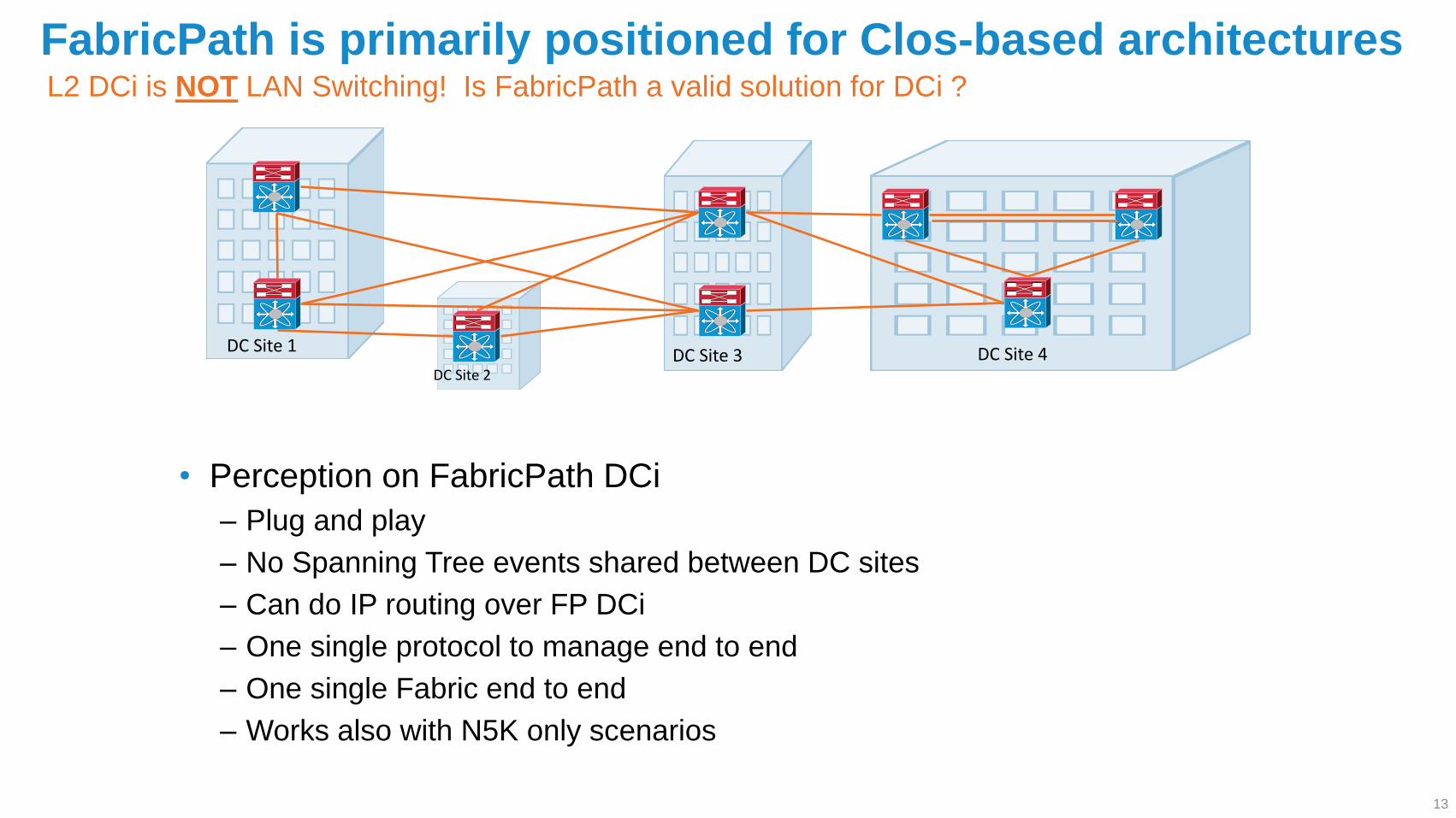
DC Site 2 DC Site 3 DC Site 4 DC Site 1
L2 DCi is NOT LAN Switching! Is FabricPath a valid solution for DCi ?
FabricPath is primarily positioned for Clos-based architectures
• Perception on FabricPath DCi
‒ Plug and play
‒ No Spanning Tree events shared between DC sites
‒ Can do IP routing over FP DCi
‒ One single protocol to manage end to end
‒ One single Fabric end to end
‒ Works also with N5K only scenarios
13
© 2012 Cisco and/or its affiliates. All rights reserved. BRKDCT-3060 Cisco Public
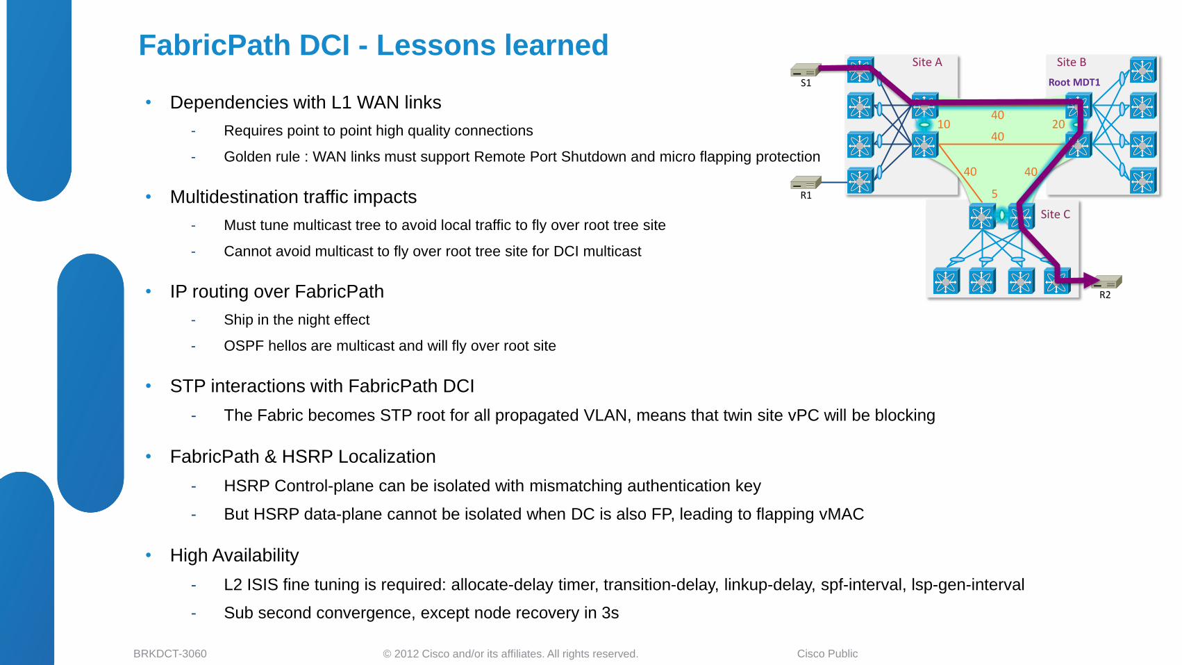
• Dependencies with L1 WAN links
- Requires point to point high quality connections
- Golden rule : WAN links must support Remote Port Shutdown and micro flapping protection
• Multidestination traffic impacts
- Must tune multicast tree to avoid local traffic to fly over root tree site
- Cannot avoid multicast to fly over root tree site for DCI multicast
• IP routing over FabricPath
- Ship in the night effect
- OSPF hellos are multicast and will fly over root site
• STP interactions with FabricPath DCI
- The Fabric becomes STP root for all propagated VLAN, means that twin site vPC will be blocking
• FabricPath & HSRP Localization
- HSRP Control-plane can be isolated with mismatching authentication key
- But HSRP data-plane cannot be isolated when DC is also FP, leading to flapping vMAC
• High Availability
- L2 ISIS fine tuning is required: allocate-delay timer, transition-delay, linkup-delay, spf-interval, lsp-gen-interval
- Sub second convergence, except node recovery in 3s
FabricPath DCI - Lessons learned
Root MDT1 S1
R2
10 20 40
40
5
40 40
Site C
Site B
R1
Site A
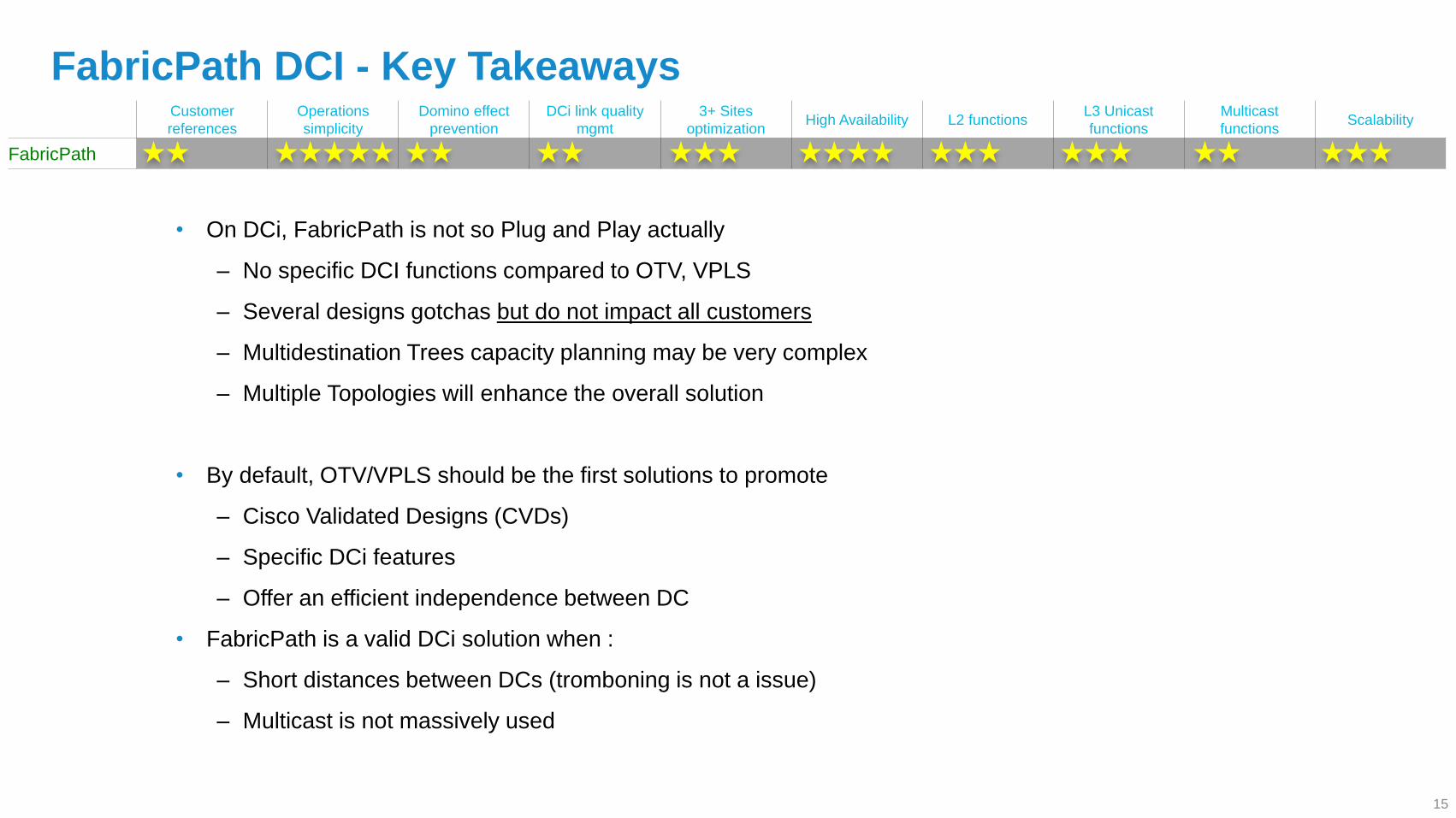
FabricPath DCI - Key Takeaways
• On DCi, FabricPath is not so Plug and Play actually
‒ No specific DCI functions compared to OTV, VPLS
‒ Several designs gotchas but do not impact all customers
‒ Multidestination Trees capacity planning may be very complex
‒ Multiple Topologies will enhance the overall solution
• By default, OTV/VPLS should be the first solutions to promote
‒ Cisco Validated Designs (CVDs)
‒ Specific DCi features
‒ Offer an efficient independence between DC
• FabricPath is a valid DCi solution when :
‒ Short distances between DCs (tromboning is not a issue)
‒ Multicast is not massively used
Customer
references
Operations
simplicity
Domino effect
prevention
DCi link quality
mgmt
3+ Sites
optimization High Availability L2 functions
L3 Unicast
functions
Multicast
functions Scalability
FabricPath
15
© 2012 Cisco and/or its affiliates. All rights reserved. BRKDCT-3060 Cisco Public
• DCI Business Drivers and Solutions Overview
• LAN Extension Deployment Scenarios
Ethernet Based Solutions
MPLS Based Solutions
EoMPLS
VPLS
H-VPLS
IP Based Solutions
• LISP for DCI Deployments
LISP and Path Optimization
LISP as L3 DCI
• Summary and Q&A
Agenda
16
© 2012 Cisco and/or its affiliates. All rights reserved. BRKDCT-3060 Cisco Public
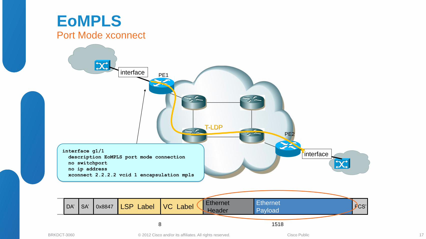
interface
interface
PE1
PE2
interface g1/1
description EoMPLS port mode connection
no switchport
no ip address
xconnect 2.2.2.2 vcid 1 encapsulation mpls
T-LDP
LSP Label VC Label Ethernet
Header
Ethernet
Payload 0x8847 DA’ SA’ FCS’
1518 8
EoMPLS Port Mode xconnect
17
© 2012 Cisco and/or its affiliates. All rights reserved. BRKDCT-3060 Cisco Public
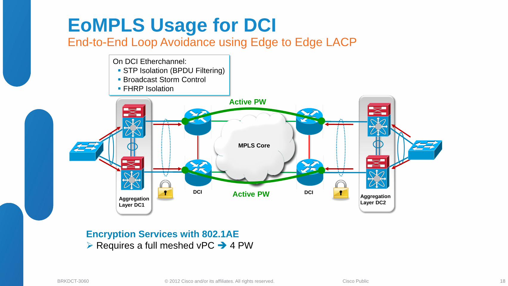
Aggregation
Layer DC1
DCI DCI Aggregation
Layer DC2
On DCI Etherchannel:
STP Isolation (BPDU Filtering)
Broadcast Storm Control
FHRP Isolation
MPLS Core
Active PW
Active PW
Encryption Services with 802.1AE
Requires a full meshed vPC 4 PW
EoMPLS Usage for DCI End-to-End Loop Avoidance using Edge to Edge LACP
18
© 2012 Cisco and/or its affiliates. All rights reserved. BRKDCT-3060 Cisco Public
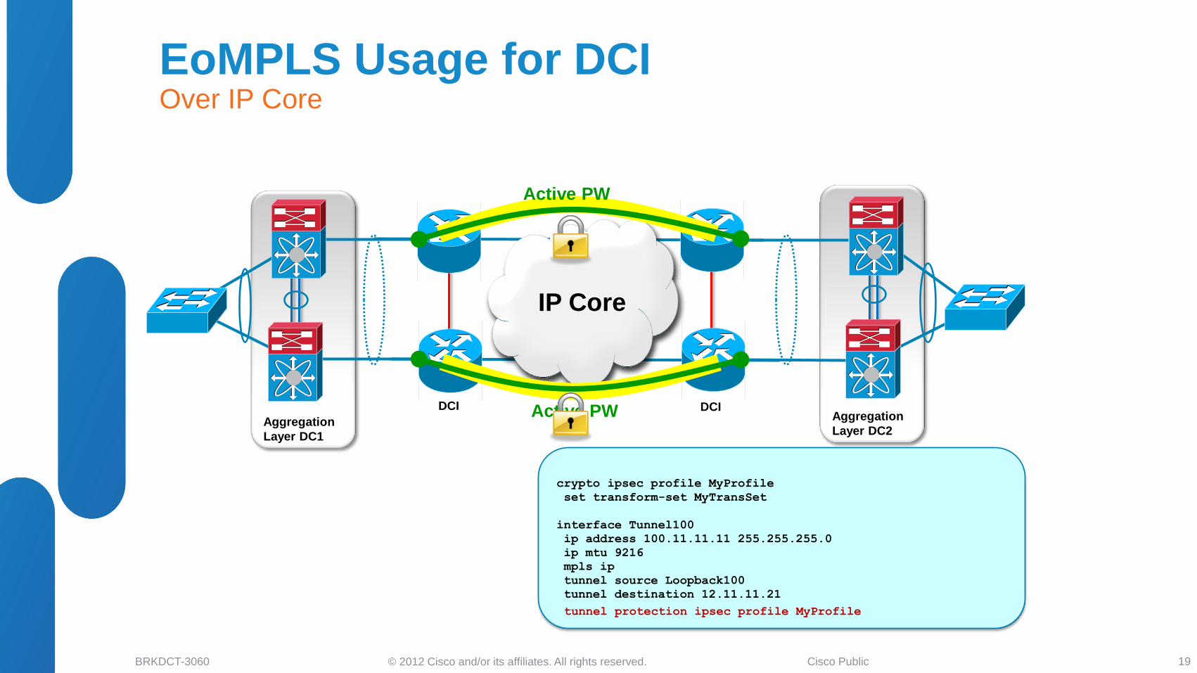
Aggregation
Layer DC1
DCI DCI Aggregation
Layer DC2
IP Core
Active PW
Active PW
crypto ipsec profile MyProfile
set transform-set MyTransSet
interface Tunnel100
ip address 100.11.11.11 255.255.255.0
ip mtu 9216
mpls ip
tunnel source Loopback100
tunnel destination 12.11.11.21
tunnel protection ipsec profile MyProfile
EoMPLS Usage for DCI Over IP Core
19
© 2012 Cisco and/or its affiliates. All rights reserved. BRKDCT-3060 Cisco Public
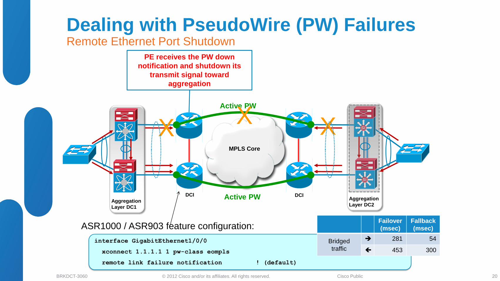
MPLS Core
Aggregation
Layer DC1
DCI DCI Aggregation
Layer DC2
PE receives the PW down
notification and shutdown its
transmit signal toward
aggregation
X X SiSi
SiSi
Active PW
Active PW
X
ASR1000 / ASR903 feature configuration:
interface GigabitEthernet1/0/0
xconnect 1.1.1.1 1 pw-class eompls
remote link failure notification ! (default)
Failover
(msec)
Fallback
(msec)
Bridged
traffic
281 54
453 300
Dealing with PseudoWire (PW) Failures Remote Ethernet Port Shutdown
20
© 2012 Cisco and/or its affiliates. All rights reserved. BRKDCT-3060 Cisco Public
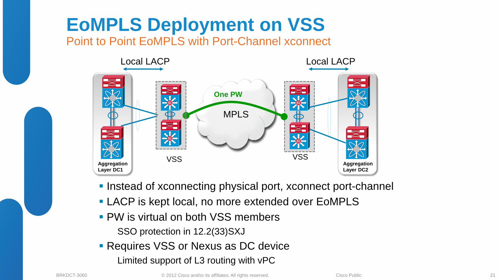
Instead of xconnecting physical port, xconnect port-channel
LACP is kept local, no more extended over EoMPLS
PW is virtual on both VSS members
SSO protection in 12.2(33)SXJ
Requires VSS or Nexus as DC device
Limited support of L3 routing with vPC
MPLS
Local LACP Local LACP
One PW
Aggregation
Layer DC1
SiSi
SiSi
VSS
SiSi
SiSi
VSS Aggregation
Layer DC2
EoMPLS Deployment on VSS Point to Point EoMPLS with Port-Channel xconnect
21

© 2012 Cisco and/or its affiliates. All rights reserved. BRKDCT-3060 Cisco Public
• DCI Business Drivers and Solutions Overview
• LAN Extension Deployment Scenarios
Ethernet Based Solutions
MPLS Based Solutions
EoMPLS
VPLS
H-VPLS
IP Based Solutions
• LISP for DCI Deployments
LISP and Path Optimization
LISP as L3 DCI
• Summary and Q&A
Agenda
22
© 2012 Cisco and/or its affiliates. All rights reserved. BRKDCT-3060 Cisco Public
MPLS
Core
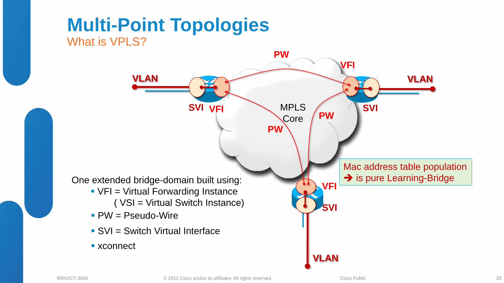
One extended bridge-domain built using:
VFI = Virtual Forwarding Instance
( VSI = Virtual Switch Instance)
VFI
VFI
VFI
PW
PW
PW
VLAN VLAN
VLAN
SVI
SVI SVI
Mac address table population
is pure Learning-Bridge
PW = Pseudo-Wire
SVI = Switch Virtual Interface
xconnect
Multi-Point Topologies What is VPLS?
23
© 2012 Cisco and/or its affiliates. All rights reserved. BRKDCT-3060 Cisco Public
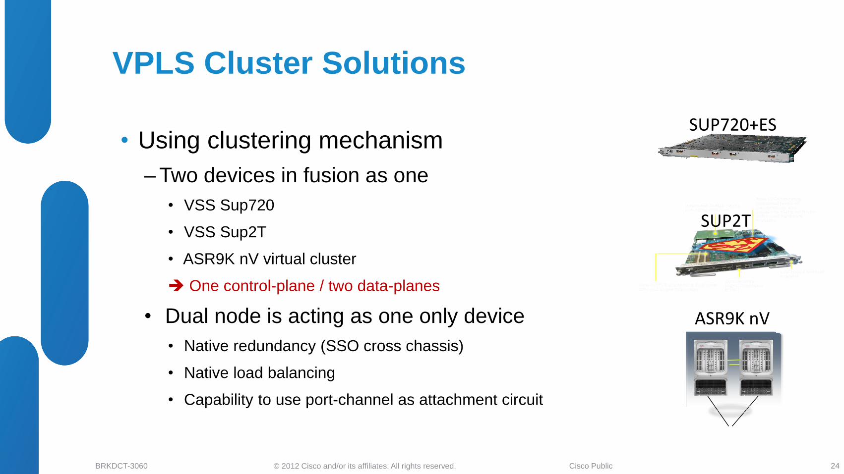
• Using clustering mechanism
‒ Two devices in fusion as one
• VSS Sup720
• VSS Sup2T
• ASR9K nV virtual cluster
One control-plane / two data-planes
• Dual node is acting as one only device
• Native redundancy (SSO cross chassis)
• Native load balancing
• Capability to use port-channel as attachment circuit
SUP720+ES
SUP2T
ASR9K nV
VPLS Cluster Solutions
24
© 2012 Cisco and/or its affiliates. All rights reserved. BRKDCT-3060 Cisco Public
SiSi
SiSi
SiSi
SiSi
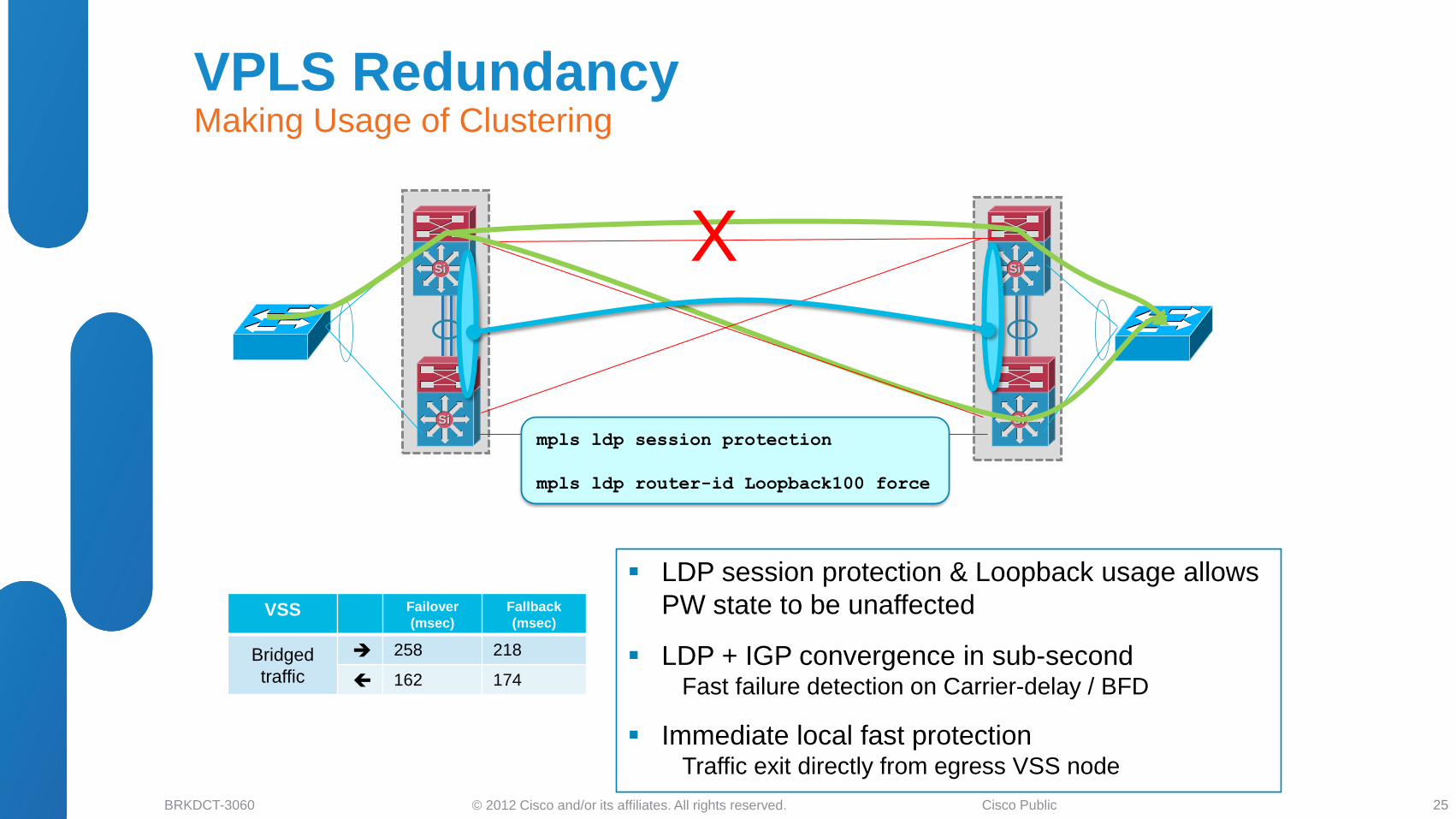
LDP session protection & Loopback usage allows
PW state to be unaffected
LDP + IGP convergence in sub-second Fast failure detection on Carrier-delay / BFD
Immediate local fast protection Traffic exit directly from egress VSS node
X
VSS Failover
(msec)
Fallback
(msec)
Bridged
traffic
258 218
162 174
mpls ldp session protection
mpls ldp router-id Loopback100 force
VPLS Redundancy Making Usage of Clustering
25
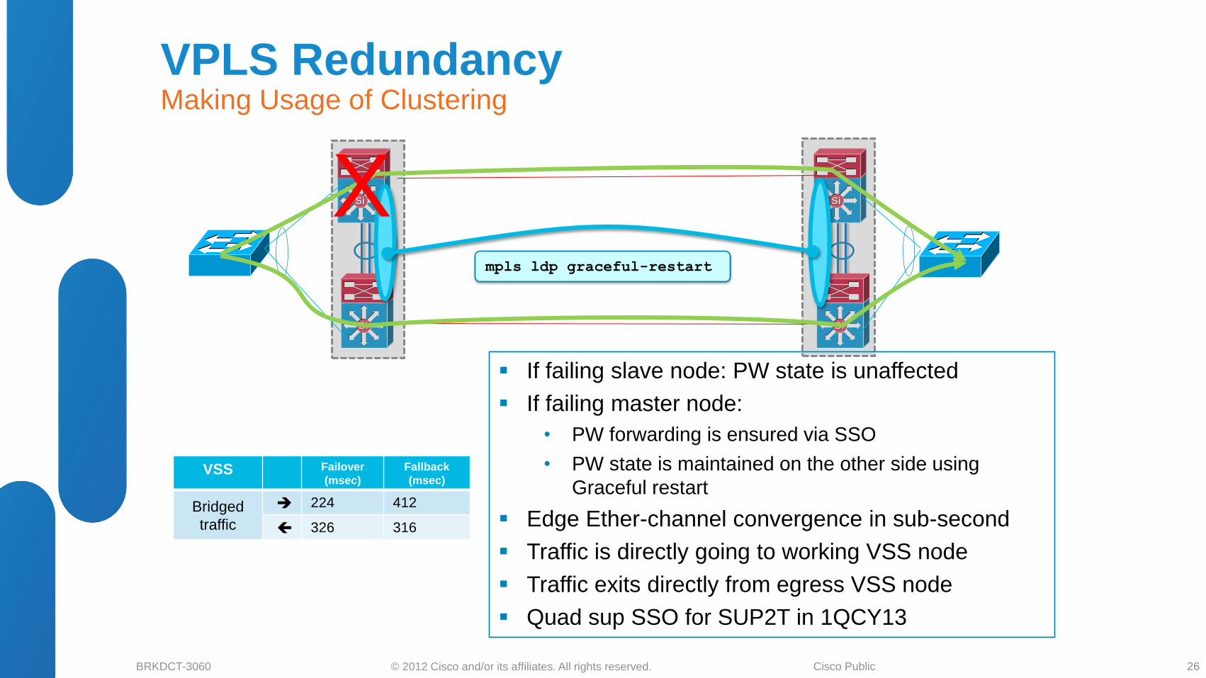
© 2012 Cisco and/or its affiliates. All rights reserved. BRKDCT-3060 Cisco Public
SiSi
SiSi
SiSi
SiSi
If failing slave node: PW state is unaffected
If failing master node:
• PW forwarding is ensured via SSO
• PW state is maintained on the other side using
Graceful restart
Edge Ether-channel convergence in sub-second
Traffic is directly going to working VSS node
Traffic exits directly from egress VSS node
Quad sup SSO for SUP2T in 1QCY13
VSS Failover
(msec)
Fallback
(msec)
Bridged
traffic
224 412
326 316
mpls ldp graceful-restart
X
VPLS Redundancy Making Usage of Clustering
26
© 2012 Cisco and/or its affiliates. All rights reserved. BRKDCT-3060 Cisco Public
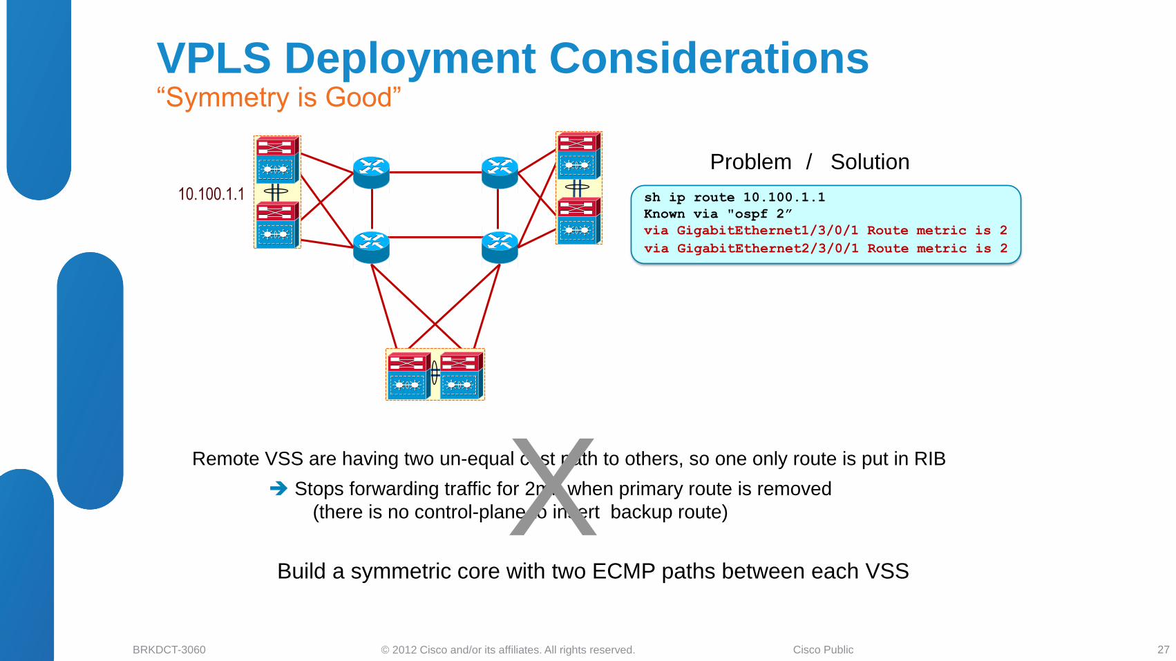
Problem
Remote VSS are having two un-equal cost path to others, so one only route is put in RIB
10.100.1.1
/ Solution
Stops forwarding traffic for 2mn when primary route is removed
(there is no control-plane to insert backup route)
Build a symmetric core with two ECMP paths between each VSS
X
sh ip route 10.100.1.1
Known via "ospf 2”
via GigabitEthernet1/3/0/1 Route metric is 2
via GigabitEthernet2/3/0/1 Route metric is 2
VPLS Deployment Considerations “Symmetry is Good”
27
© 2012 Cisco and/or its affiliates. All rights reserved. BRKDCT-3060 Cisco Public
Si
Si Si
Si
SiSi
SiSi
SiSi
SiSi Rem: One PW per VLAN per destination
Any card type facing edge
SUP720 + SIP-400 facing core (5Gbps) or
SUP720 + ES-40 (40Gbps) support with
12.2(33)SXJ
SUP2T
#sh mpls l2 vc
Local intf Local circuit Dest address VC ID Status
------------- ------------- ------------ ----- ------
VFI VFI_610_ VFI 10.100.2.2 610 UP
VFI VFI_610_ VFI 10.100.3.3 610 UP
VFI VFI_611_ VFI 10.100.2.2 611 UP
VFI VFI_611_ VFI 10.100.3.3 611 UP
interface Virtual-Ethernet1
transport vpls mesh
neighbor 10.100.2.2 pw-class Core
neighbor 10.100.3.3 pw-class Core
pseudowire-class Core
encapsulation mpls
switchport
switchport mode trunk
switchport trunk allowed vlan 610-619
VSS - A-VPLS CLI SUP2T in 15.1SY
28
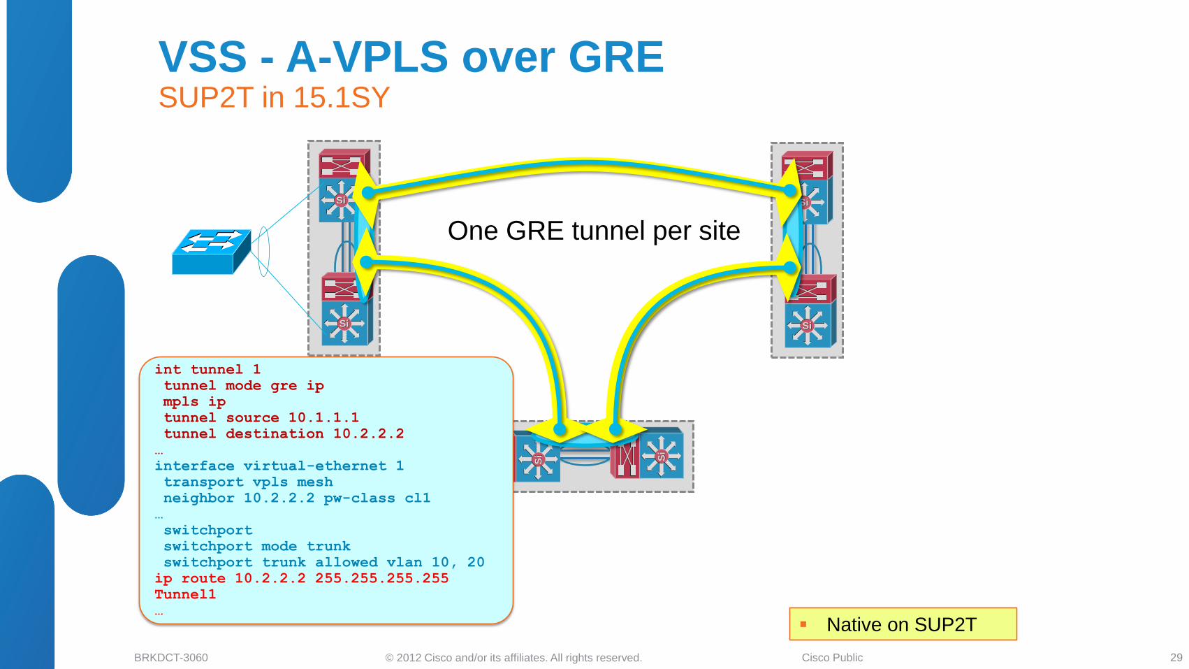
© 2012 Cisco and/or its affiliates. All rights reserved. BRKDCT-3060 Cisco Public
Si
Si Si
Si
SiSi
SiSi
SiSi
SiSi
One GRE tunnel per site
Native on SUP2T
int tunnel 1
tunnel mode gre ip
mpls ip
tunnel source 10.1.1.1
tunnel destination 10.2.2.2
…
interface virtual-ethernet 1
transport vpls mesh
neighbor 10.2.2.2 pw-class cl1
…
switchport
switchport mode trunk
switchport trunk allowed vlan 10, 20
ip route 10.2.2.2 255.255.255.255
Tunnel1
…
VSS - A-VPLS over GRE SUP2T in 15.1SY
29
© 2012 Cisco and/or its affiliates. All rights reserved. BRKDCT-3060 Cisco Public
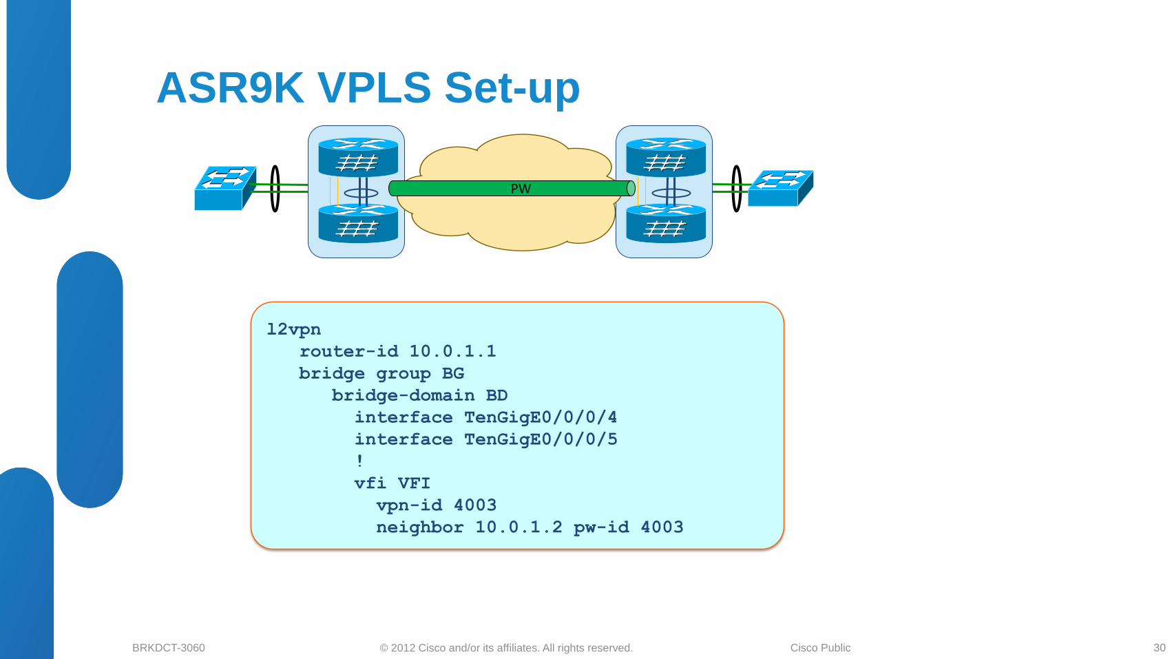
PW
ASR9K VPLS Set-up
l2vpn
router-id 10.0.1.1
bridge group BG
bridge-domain BD
interface TenGigE0/0/0/4
interface TenGigE0/0/0/5
!
vfi VFI
vpn-id 4003
neighbor 10.0.1.2 pw-id 4003
30
© 2012 Cisco and/or its affiliates. All rights reserved. BRKDCT-3060 Cisco Public
• DCI Business Drivers and Solutions Overview
• LAN Extension Deployment Scenarios
Ethernet Based Solutions
MPLS Based Solutions
EoMPLS
VPLS
H-VPLS
IP Based Solutions
• LISP for DCI Deployments
LISP and Path Optimization
LISP as L3 DCI
• Summary and Q&A
Agenda
31
© 2012 Cisco and/or its affiliates. All rights reserved. BRKDCT-3060 Cisco Public
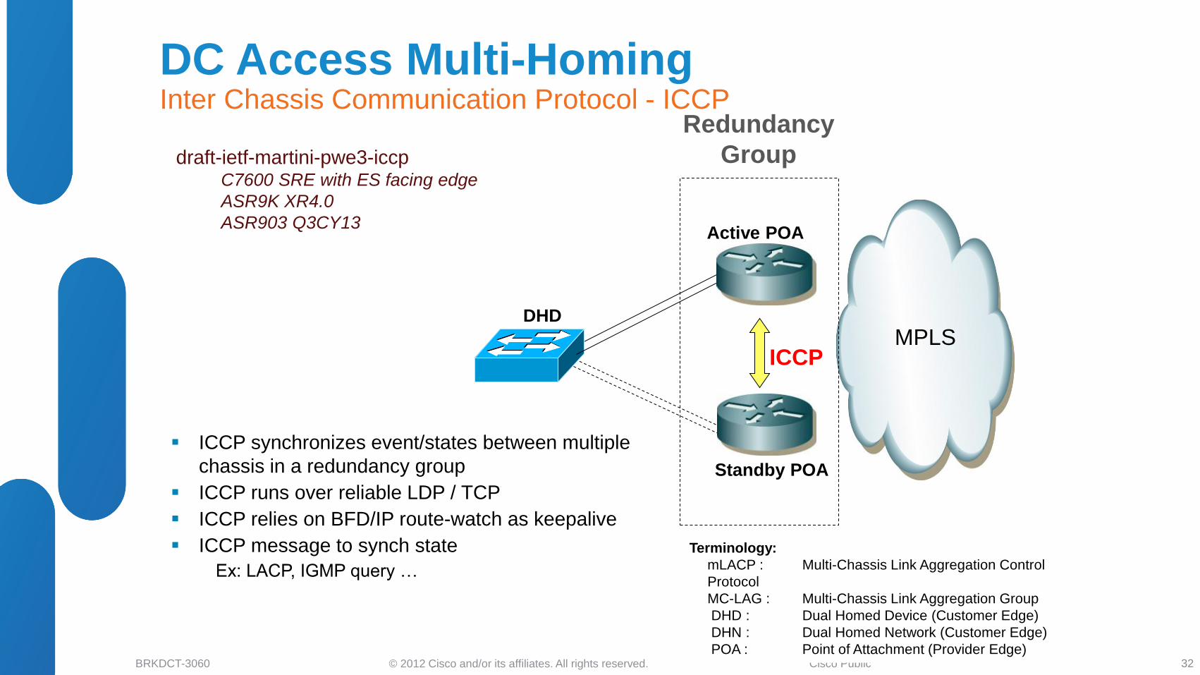
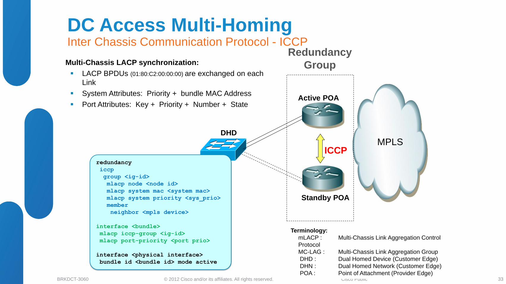
DHD
Active POA
Standby POA
Redundancy
Group
MPLS
Terminology:
mLACP : Multi-Chassis Link Aggregation Control
Protocol
MC-LAG : Multi-Chassis Link Aggregation Group
DHD : Dual Homed Device (Customer Edge)
DHN : Dual Homed Network (Customer Edge)
POA : Point of Attachment (Provider Edge)
ICCP
ICCP synchronizes event/states between multiple
chassis in a redundancy group
ICCP runs over reliable LDP / TCP
ICCP relies on BFD/IP route-watch as keepalive
ICCP message to synch state
Ex: LACP, IGMP query …
draft-ietf-martini-pwe3-iccp C7600 SRE with ES facing edge
ASR9K XR4.0
ASR903 Q3CY13
DC Access Multi-Homing Inter Chassis Communication Protocol - ICCP
32
© 2012 Cisco and/or its affiliates. All rights reserved. BRKDCT-3060 Cisco Public
DHD
Active POA
Standby POA
Redundancy
Group
MPLS
Terminology:
mLACP : Multi-Chassis Link Aggregation Control
Protocol
MC-LAG : Multi-Chassis Link Aggregation Group
DHD : Dual Homed Device (Customer Edge)
DHN : Dual Homed Network (Customer Edge)
POA : Point of Attachment (Provider Edge)
ICCP
Multi-Chassis LACP synchronization:
LACP BPDUs (01:80:C2:00:00:00) are exchanged on each
Link
System Attributes: Priority + bundle MAC Address
Port Attributes: Key + Priority + Number + State
redundancy
iccp
group <ig-id>
mlacp node <node id>
mlacp system mac <system mac>
mlacp system priority <sys_prio>
member
neighbor <mpls device>
interface <bundle>
mlacp iccp-group <ig-id>
mlacp port-priority <port prio>
interface <physical interface>
bundle id <bundle id> mode active
DC Access Multi-Homing Inter Chassis Communication Protocol - ICCP
33
© 2012 Cisco and/or its affiliates. All rights reserved. BRKDCT-3060 Cisco Public
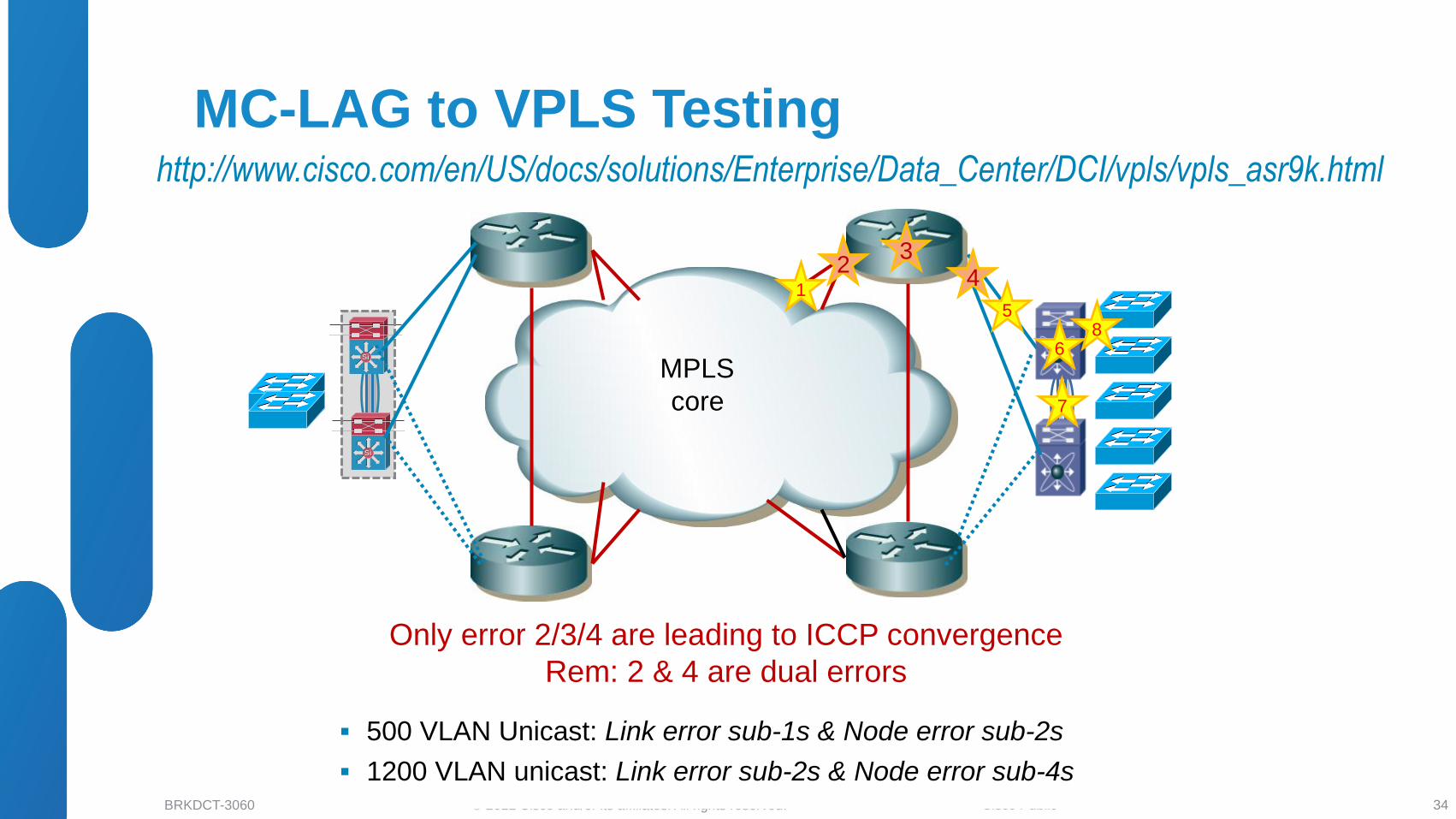
http://www.cisco.com/en/US/docs/solutions/Enterprise/Data_Center/DCI/vpls/vpls_asr9k.html
SiSi
SiSi
MPLS
core
1
2 3
4
5
6
7
8
Only error 2/3/4 are leading to ICCP convergence
Rem: 2 & 4 are dual errors
500 VLAN Unicast: Link error sub-1s & Node error sub-2s
1200 VLAN unicast: Link error sub-2s & Node error sub-4s
MC-LAG to VPLS Testing
34
© 2012 Cisco and/or its affiliates. All rights reserved. BRKDCT-3060 Cisco Public
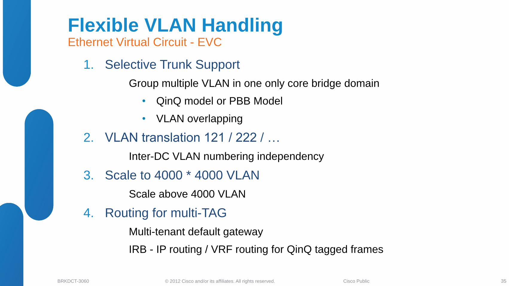
1. Selective Trunk Support
Group multiple VLAN in one only core bridge domain
• QinQ model or PBB Model
• VLAN overlapping
2. VLAN translation 121 / 222 / …
Inter-DC VLAN numbering independency
3. Scale to 4000 * 4000 VLAN
Scale above 4000 VLAN
4. Routing for multi-TAG
Multi-tenant default gateway
IRB - IP routing / VRF routing for QinQ tagged frames
Flexible VLAN Handling Ethernet Virtual Circuit - EVC
35
© 2012 Cisco and/or its affiliates. All rights reserved. BRKDCT-3060 Cisco Public
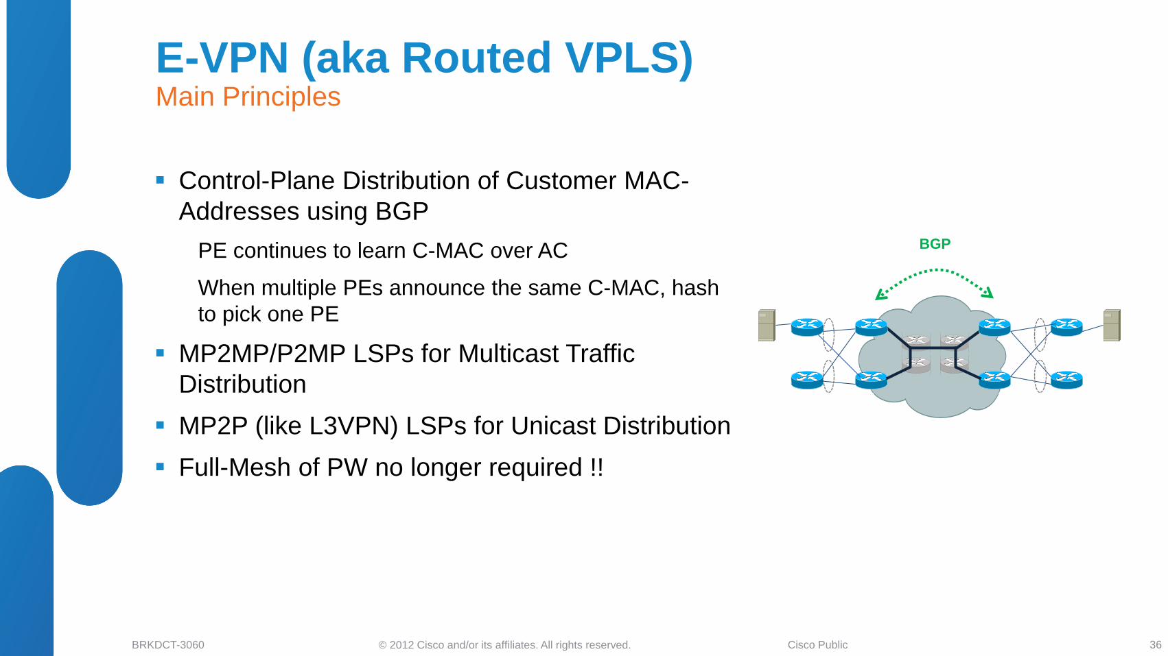
Control-Plane Distribution of Customer MAC-
Addresses using BGP
PE continues to learn C-MAC over AC
When multiple PEs announce the same C-MAC, hash
to pick one PE
MP2MP/P2MP LSPs for Multicast Traffic
Distribution
MP2P (like L3VPN) LSPs for Unicast Distribution
Full-Mesh of PW no longer required !!
BGP
PE PE
PE PE
E-VPN (aka Routed VPLS) Main Principles
36
© 2012 Cisco and/or its affiliates. All rights reserved. BRKDCT-3060 Cisco Public
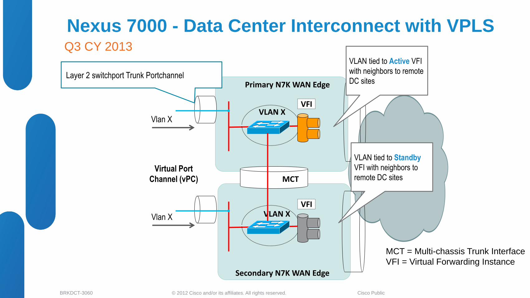
Nexus 7000 - Data Center Interconnect with VPLS Q3 CY 2013
VFI VLAN X
Primary N7K WAN Edge
MCT = Multi-chassis Trunk Interface
VFI = Virtual Forwarding Instance
Layer 2 switchport Trunk Portchannel
VFI VLAN X
MCT
Secondary N7K WAN Edge
Virtual Port
Channel (vPC)
Vlan X
Vlan X
VLAN tied to Active VFI
with neighbors to remote
DC sites
VLAN tied to Standby
VFI with neighbors to
remote DC sites
© 2012 Cisco and/or its affiliates. All rights reserved. BRKDCT-3060 Cisco Public
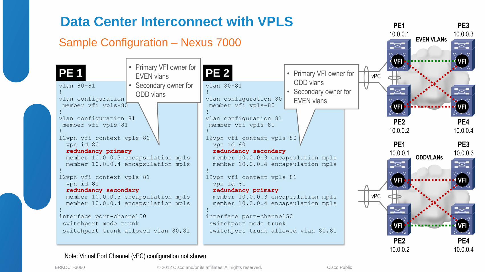
Data Center Interconnect with VPLS
Sample Configuration – Nexus 7000
vlan 80-81
!
vlan configuration 80
member vfi vpls-80
!
vlan configuration 81
member vfi vpls-81
!
l2vpn vfi context vpls-80
vpn id 80
redundancy primary
member 10.0.0.3 encapsulation mpls
member 10.0.0.4 encapsulation mpls
!
l2vpn vfi context vpls-81
vpn id 81
redundancy secondary
member 10.0.0.3 encapsulation mpls
member 10.0.0.4 encapsulation mpls
!
interface port-channel50
switchport mode trunk
switchport trunk allowed vlan 80,81
vlan 80-81
!
vlan configuration 80
member vfi vpls-80
!
vlan configuration 81
member vfi vpls-81
!
l2vpn vfi context vpls-80
vpn id 80
redundancy secondary
member 10.0.0.3 encapsulation mpls
member 10.0.0.4 encapsulation mpls
!
l2vpn vfi context vpls-81
vpn id 81
redundancy primary
member 10.0.0.3 encapsulation mpls
member 10.0.0.4 encapsulation mpls
!
interface port-channel50
switchport mode trunk
switchport trunk allowed vlan 80,81
VFI
VFI
VFI
VFI
PE1 10.0.0.1
PE2 10.0.0.2
PE3 10.0.0.3
PE4 10.0.0.4
VFI
VFI
VFI
VFI
PE1 10.0.0.1
PE2 10.0.0.2
PE3 10.0.0.3
PE4 10.0.0.4
PE 1 PE 2
EVEN VLANs
ODDVLANs
• Primary VFI owner for
ODD vlans
• Secondary owner for
EVEN vlans
• Primary VFI owner for
EVEN vlans
• Secondary owner for
ODD vlans
vPC
vPC
Note: Virtual Port Channel (vPC) configuration not shown
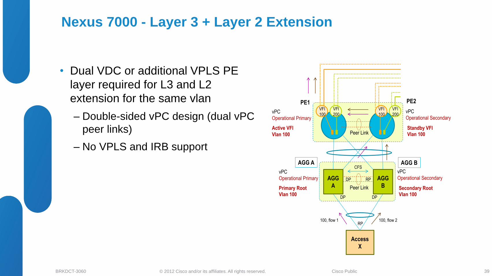
© 2012 Cisco and/or its affiliates. All rights reserved. BRKDCT-3060 Cisco Public
vPC
Operational Primary
Nexus 7000 - Layer 3 + Layer 2 Extension
• Dual VDC or additional VPLS PE
layer required for L3 and L2
extension for the same vlan
‒ Double-sided vPC design (dual vPC
peer links)
‒ No VPLS and IRB support
39
Access
X
Peer Link
vPC
Operational Primary
vPC
Operational Secondary DP RP
DP DP
RP
AGG
A
AGG
B
VFI
200
PE1 PE2
100, flow 1 100, flow 2
VFI
100
Primary Root Vlan 100
Secondary Root Vlan 100
Peer Link
vPC
Operational Secondary
Active VFI
Vlan 100
Standby VFI Vlan 100
CFS AGG A AGG B
VFI
100
VFI
200
© 2012 Cisco and/or its affiliates. All rights reserved. BRKDCT-3060 Cisco Public
• DCI Business Drivers and Solutions Overview
• LAN Extension Deployment Scenarios
Ethernet Based Solutions
MPLS Based Solutions
IP Based Solutions
OTV Technology Overview
OTV Deployment Considerations
• LISP for DCI Deployments
LISP and Path Optimization
LISP as L3 DCI
• Summary and Q&A
Agenda
40
© 2012 Cisco and/or its affiliates. All rights reserved. BRKDCT-3060 Cisco Public
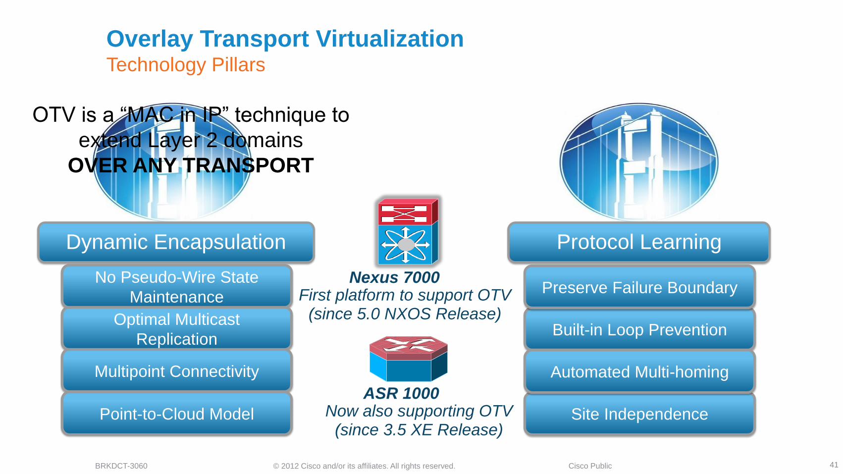
Overlay Transport Virtualization Technology Pillars
41
OTV is a “MAC in IP” technique to
extend Layer 2 domains
OVER ANY TRANSPORT
Protocol Learning
Built-in Loop Prevention
Preserve Failure Boundary
Site Independence
Automated Multi-homing
Dynamic Encapsulation
No Pseudo-Wire State
Maintenance
Optimal Multicast
Replication
Multipoint Connectivity
Point-to-Cloud Model
First platform to support OTV (since 5.0 NXOS Release)
Nexus 7000
Now also supporting OTV (since 3.5 XE Release)
ASR 1000
© 2012 Cisco and/or its affiliates. All rights reserved. BRKDCT-3060 Cisco Public
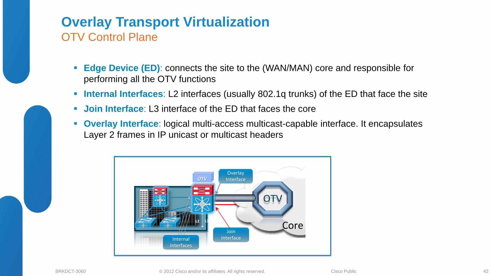
Overlay Transport Virtualization OTV Control Plane
Edge Device (ED): connects the site to the (WAN/MAN) core and responsible for
performing all the OTV functions
Internal Interfaces: L2 interfaces (usually 802.1q trunks) of the ED that face the site
Join Interface: L3 interface of the ED that faces the core
Overlay Interface: logical multi-access multicast-capable interface. It encapsulates
Layer 2 frames in IP unicast or multicast headers
OTV
Internal Interfaces
Core L2 L3
Join Interface
Overlay Interface
42
© 2012 Cisco and/or its affiliates. All rights reserved. BRKDCT-3060 Cisco Public
Transport Infrastructure
OTV OTV OTV OTV
MAC TABLE
VLAN MAC IF
100 MAC 1 Eth 2
100 MAC 2 Eth 1
100 MAC 3 IP B
100 MAC 4 IP B
MAC 1 MAC 3
MAC TABLE
VLAN MAC IF
100 MAC 1 IP A
100 MAC 2 IP A
100 MAC 3 Eth 3
100 MAC 4 Eth 4
Layer 2 Lookup
6 IP A IP B MAC 1 MAC 3 MAC 1 MAC 3
Encap 3
Decap 5
MAC 1 MAC 3 West
Site Server 1 Server 3
East
Site
4
7
IP A IP B
1
IP A IP B MAC 1 MAC 3
OTV Data Plane Inter-Site Packet Flow
43
© 2012 Cisco and/or its affiliates. All rights reserved. BRKDCT-3060 Cisco Public
IP A
West
East
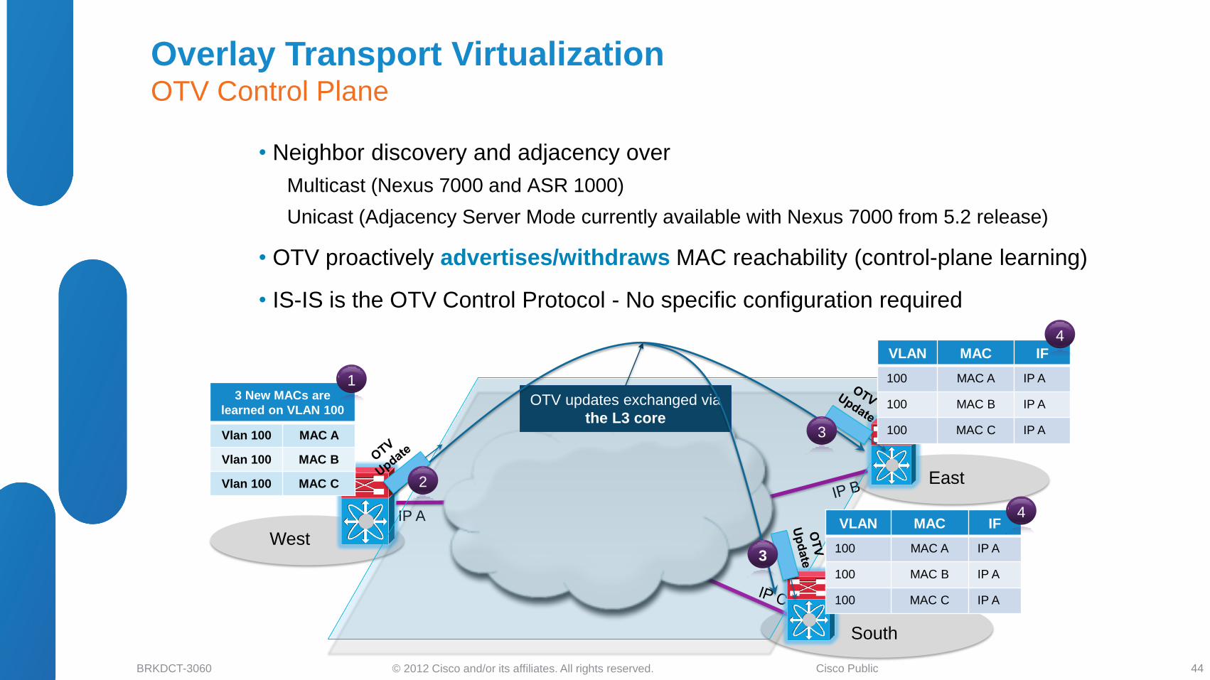
3 New MACs are
learned on VLAN 100
Vlan 100 MAC A
Vlan 100 MAC B
Vlan 100 MAC C
South
VLAN MAC IF
100 MAC A IP A
100 MAC B IP A
100 MAC C IP A
4
OTV updates exchanged via
the L3 core 3
3
2
VLAN MAC IF
100 MAC A IP A
100 MAC B IP A
100 MAC C IP A
4
3 New MACs are
learned on VLAN 100
1
Overlay Transport Virtualization OTV Control Plane
44
• Neighbor discovery and adjacency over
Multicast (Nexus 7000 and ASR 1000)
Unicast (Adjacency Server Mode currently available with Nexus 7000 from 5.2 release)
• OTV proactively advertises/withdraws MAC reachability (control-plane learning)
• IS-IS is the OTV Control Protocol - No specific configuration required
© 2012 Cisco and/or its affiliates. All rights reserved. BRKDCT-3060 Cisco Public
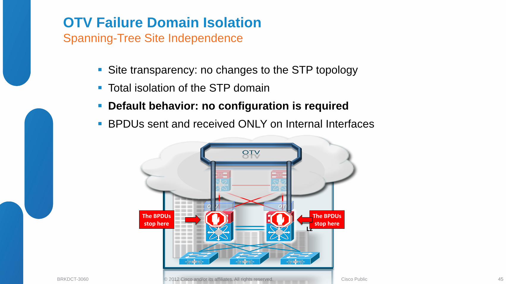
OTV Failure Domain Isolation Spanning-Tree Site Independence
45
Site transparency: no changes to the STP topology
Total isolation of the STP domain
Default behavior: no configuration is required
BPDUs sent and received ONLY on Internal Interfaces
L2
L3
OTV OTV
The BPDUs stop here
The BPDUs stop here
© 2012 Cisco and/or its affiliates. All rights reserved. BRKDCT-3060 Cisco Public
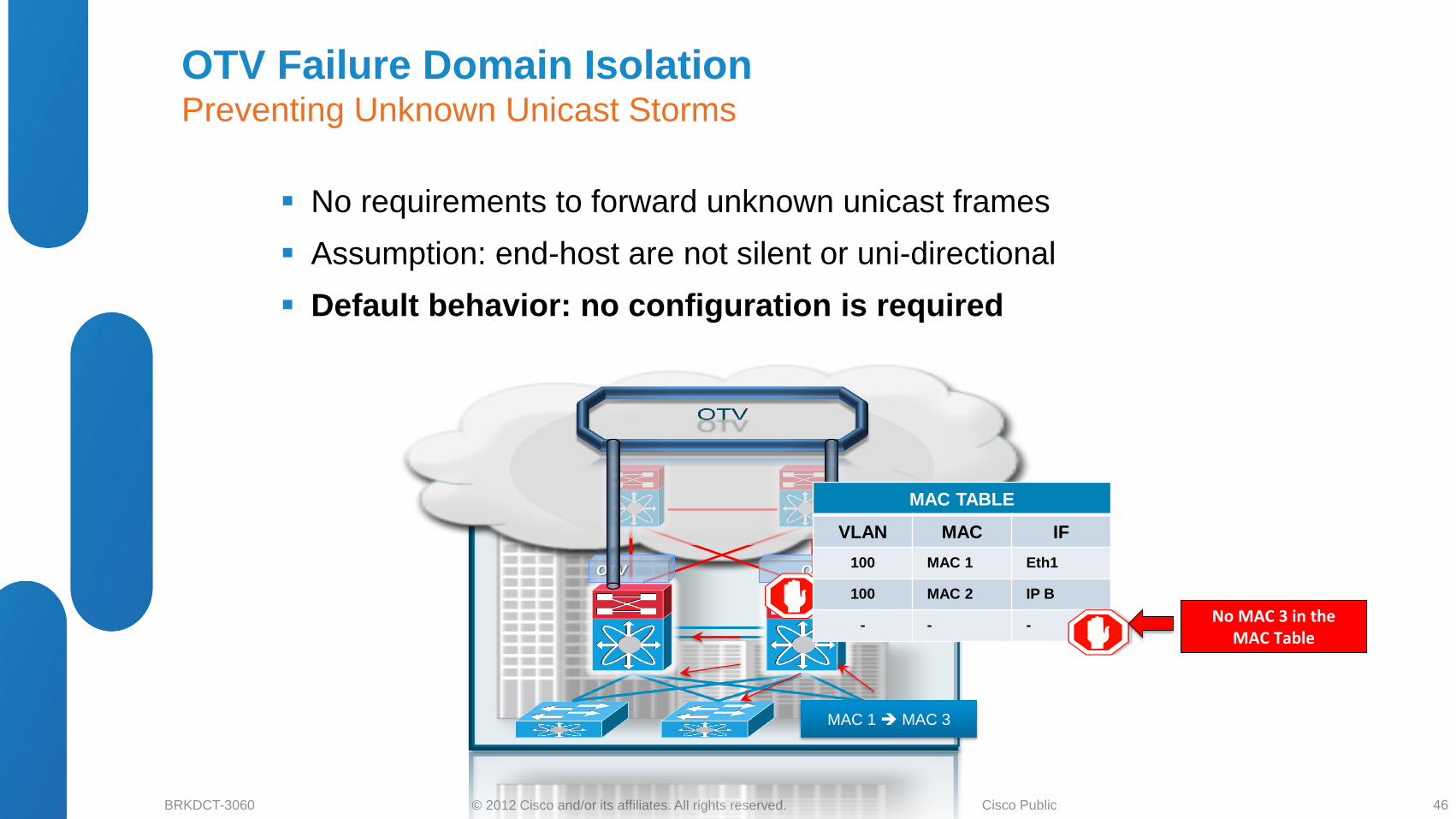
OTV Failure Domain Isolation Preventing Unknown Unicast Storms
46
No requirements to forward unknown unicast frames
Assumption: end-host are not silent or uni-directional
Default behavior: no configuration is required
L2
L3
OTV OTV
MAC TABLE
VLAN MAC IF
100 MAC 1 Eth1
100 MAC 2 IP B
- - -
MAC 1 MAC 3
No MAC 3 in the MAC Table
Remote OTV Device MAC
Table
VLAN MAC IF
100 MAC 1 IP A
101 MAC 2 IP B
47
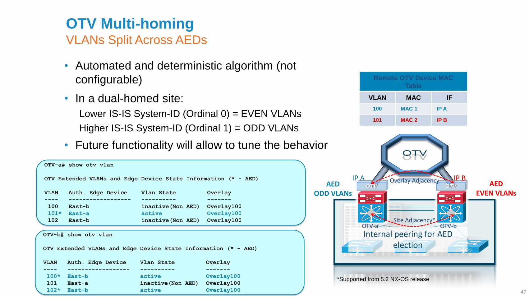
• Automated and deterministic algorithm (not
configurable)
• In a dual-homed site:
Lower IS-IS System-ID (Ordinal 0) = EVEN VLANs
Higher IS-IS System-ID (Ordinal 1) = ODD VLANs
• Future functionality will allow to tune the behavior
OTV OTV
Internal peering for AED election
AED ODD VLANs
AED EVEN VLANs
IP B IP A
Site Adjacency*
Overlay Adjacency
OTV-a# show otv vlan
OTV Extended VLANs and Edge Device State Information (* - AED)
VLAN Auth. Edge Device Vlan State Overlay
---- ------------------ ---------- -------
100 East-b inactive(Non AED) Overlay100
101* East-a active Overlay100
102 East-b inactive(Non AED) Overlay100
OTV-b# show otv vlan
OTV Extended VLANs and Edge Device State Information (* - AED)
VLAN Auth. Edge Device Vlan State Overlay
---- ------------------ ---------- -------
100* East-b active Overlay100
101 East-a inactive(Non AED) Overlay100
102* East-b active Overlay100
OTV-a OTV-b
OTV Multi-homing VLANs Split Across AEDs
*Supported from 5.2 NX-OS release
© 2012 Cisco and/or its affiliates. All rights reserved. BRKDCT-3060 Cisco Public
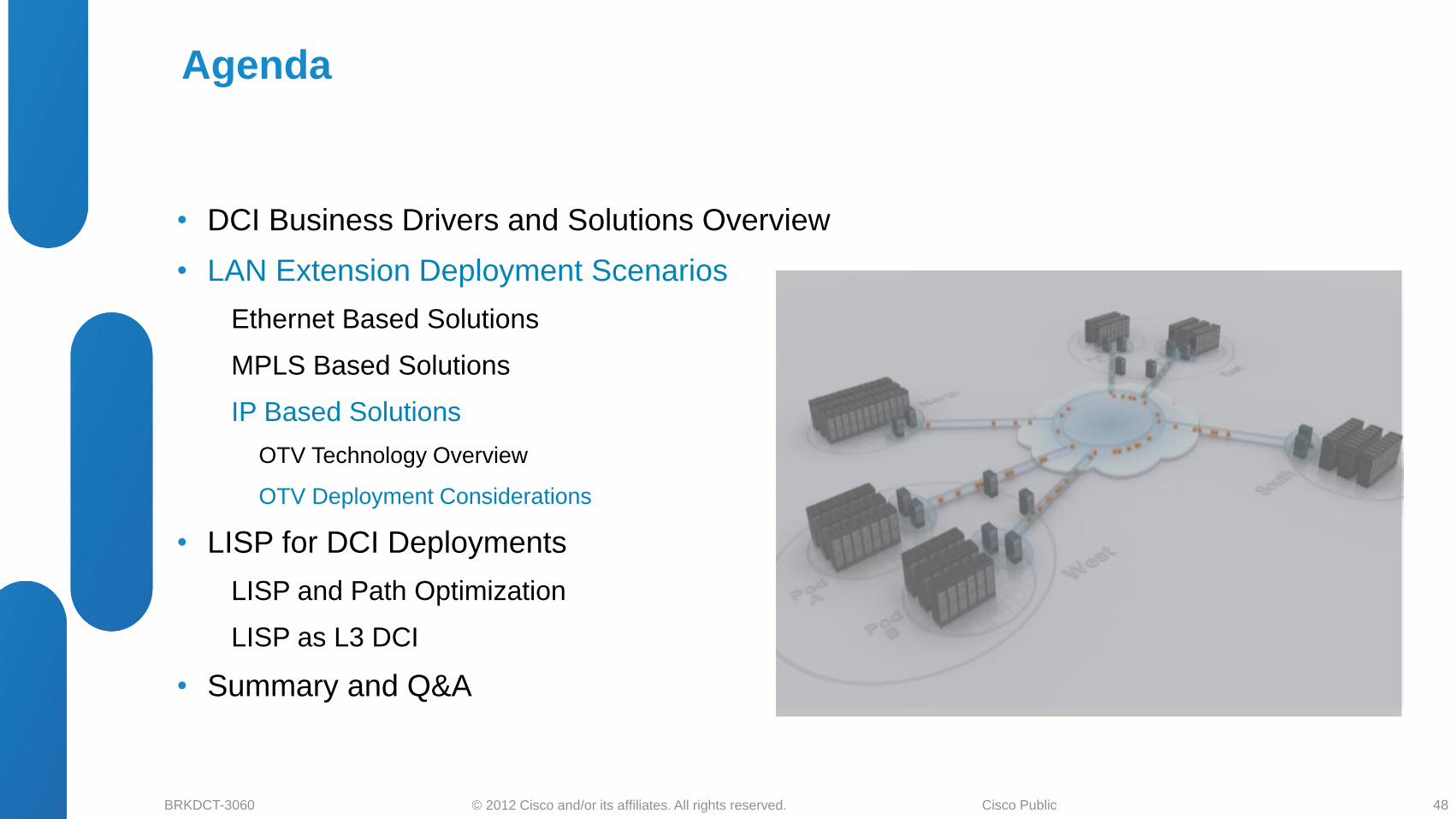
• DCI Business Drivers and Solutions Overview
• LAN Extension Deployment Scenarios
Ethernet Based Solutions
MPLS Based Solutions
IP Based Solutions
OTV Technology Overview
OTV Deployment Considerations
• LISP for DCI Deployments
LISP and Path Optimization
LISP as L3 DCI
• Summary and Q&A
Agenda
48
© 2012 Cisco and/or its affiliates. All rights reserved. BRKDCT-3060 Cisco Public
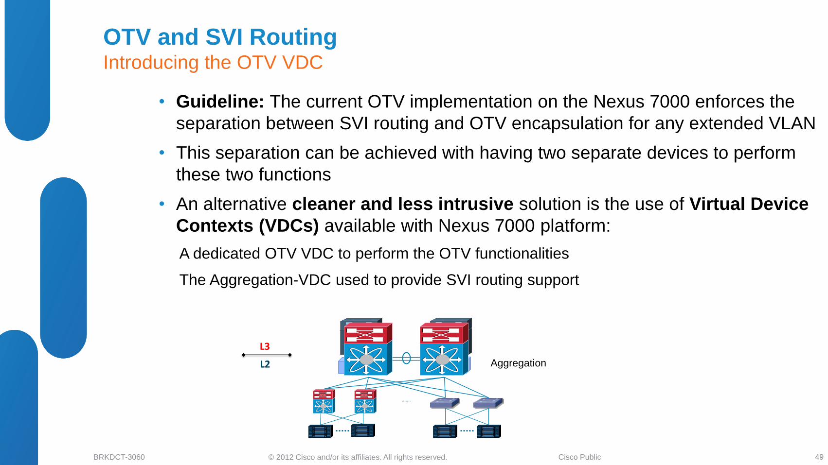
OTV and SVI Routing Introducing the OTV VDC
49
• Guideline: The current OTV implementation on the Nexus 7000 enforces the
separation between SVI routing and OTV encapsulation for any extended VLAN
• This separation can be achieved with having two separate devices to perform
these two functions
• An alternative cleaner and less intrusive solution is the use of Virtual Device
Contexts (VDCs) available with Nexus 7000 platform:
A dedicated OTV VDC to perform the OTV functionalities
The Aggregation-VDC used to provide SVI routing support
Aggregation OTV
VDC
OTV
VDC L2
L3
© 2012 Cisco and/or its affiliates. All rights reserved. BRKDCT-3060 Cisco Public
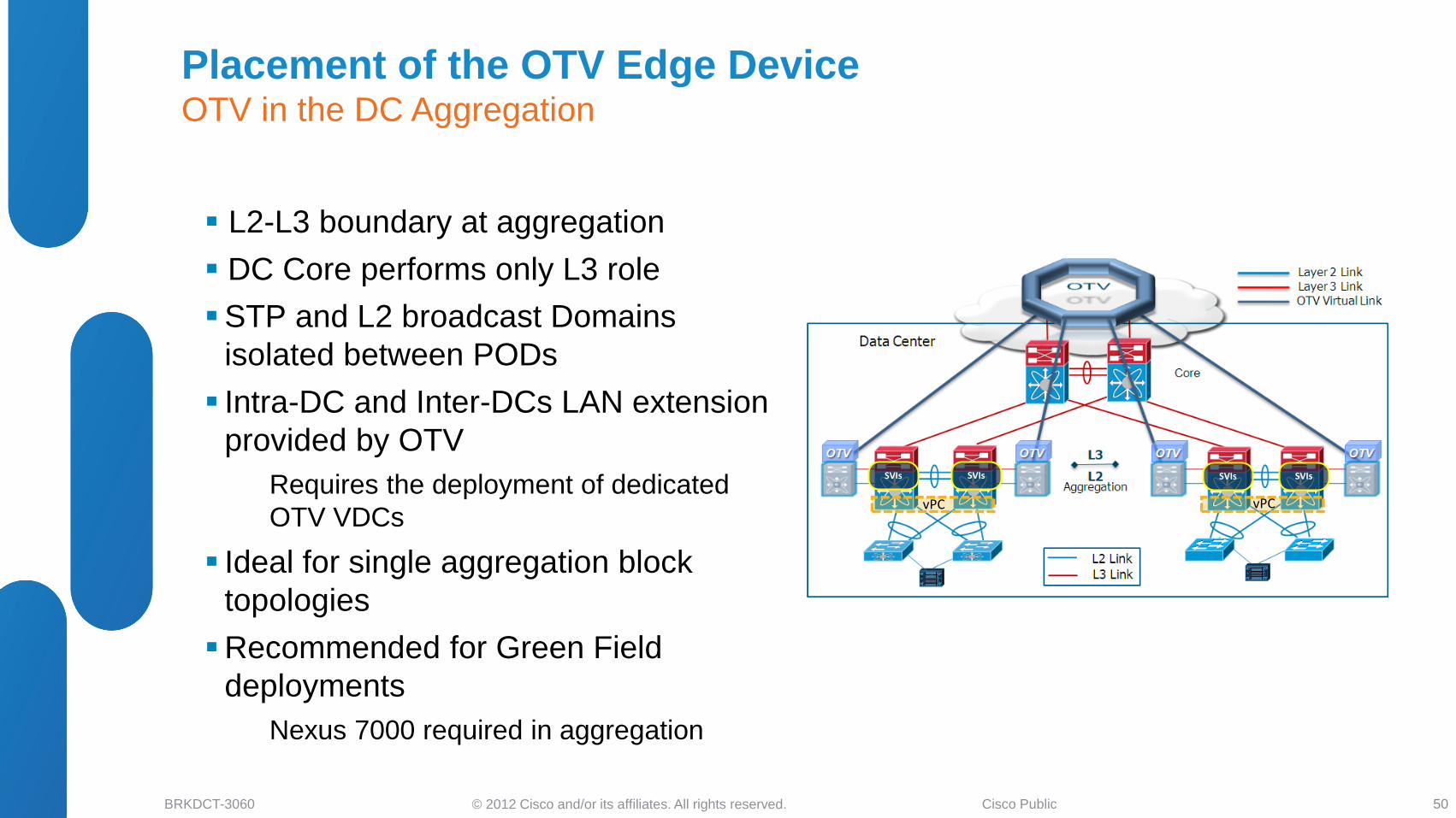
L2-L3 boundary at aggregation
DC Core performs only L3 role
STP and L2 broadcast Domains
isolated between PODs
Intra-DC and Inter-DCs LAN extension
provided by OTV
Requires the deployment of dedicated
OTV VDCs
Ideal for single aggregation block
topologies
Recommended for Green Field
deployments
Nexus 7000 required in aggregation
vPC vPC
SVIs SVIs SVIs SVIs
Placement of the OTV Edge Device OTV in the DC Aggregation
50
© 2012 Cisco and/or its affiliates. All rights reserved. BRKDCT-3060 Cisco Public
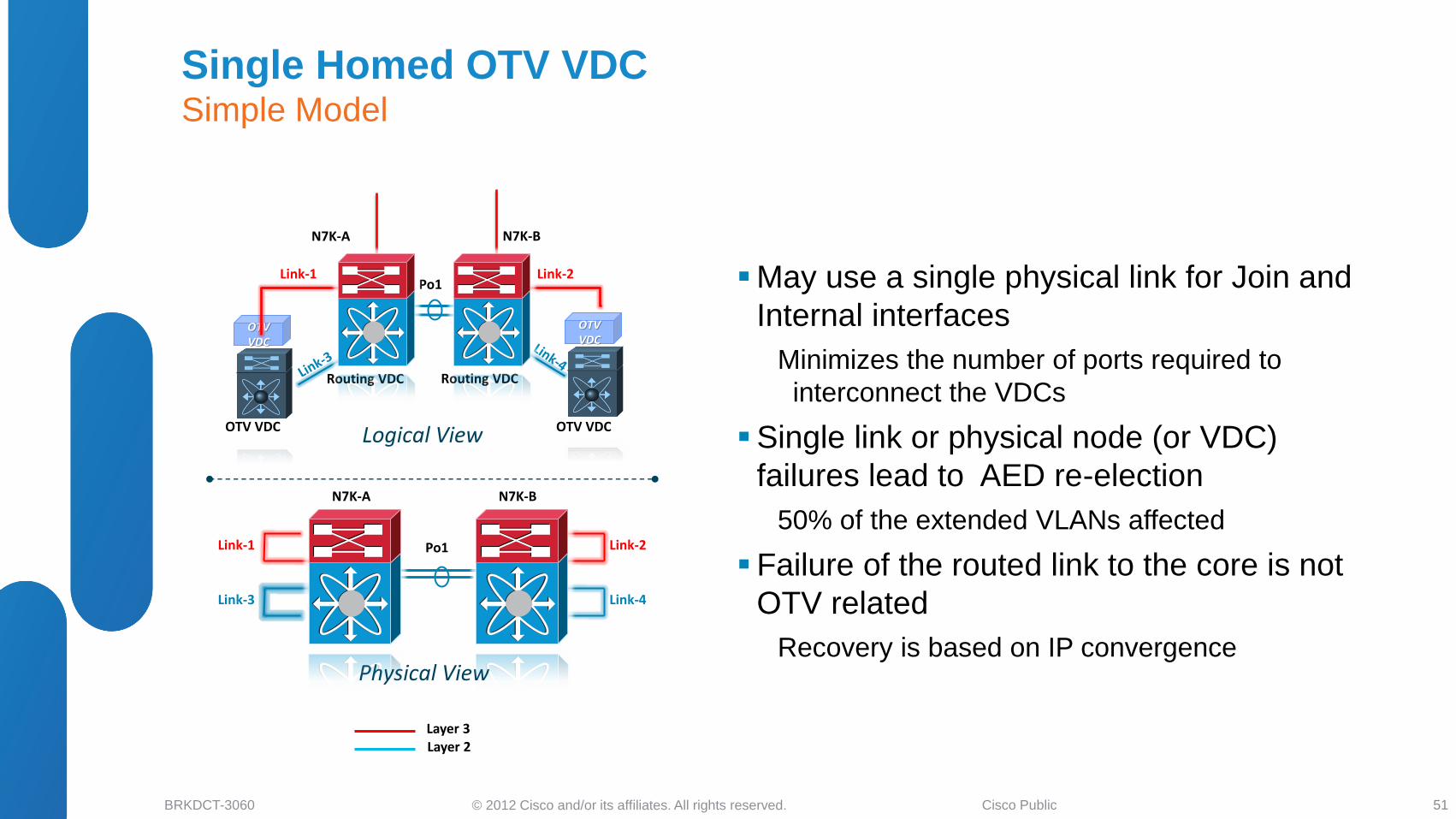
OTV VDC
OTV VDC
Link-1 Link-2 Po1
N7K-A
N7K-B
Link-1
Link-3 Link-4
Link-2 Po1
Physical View
Logical View OTV VDC OTV VDC
N7K-A
N7K-B
Routing VDC Routing VDC
Layer 3 Layer 2
May use a single physical link for Join and
Internal interfaces
Minimizes the number of ports required to
interconnect the VDCs
Single link or physical node (or VDC)
failures lead to AED re-election
50% of the extended VLANs affected
Failure of the routed link to the core is not
OTV related
Recovery is based on IP convergence
Single Homed OTV VDC Simple Model
51

© 2012 Cisco and/or its affiliates. All rights reserved. BRKDCT-3060 Cisco Public
Logical Port-channels used for the Join
and the Internal interfaces Increases the number of physical interfaces
required to interconnect the VDCs
Traffic recovery after single link failure
event based on port-channel re-hashing
No need for AED re-election
Physical node (or VDC) failure still
requires AED re-election
In the current implementation may cause few
seconds of outage (for 50% of the extended
VLANs)
OTV VDC
OTV VDC
Po1
N7K-A
N7K-B
Link 5 Link 7
Po1
Physical View
Logical View OTV VDC OTV VDC
N7K-A
N7K-B
Links 1-2
Layer 3 Layer 2
Links 3-4
Routing VDC Routing VDC
Links 1-2 Links 3-4
Link 8
Link 6
Dual Homed OTV VDC Improving the Design Resiliency
52
© 2012 Cisco and/or its affiliates. All rights reserved. BRKDCT-3060 Cisco Public
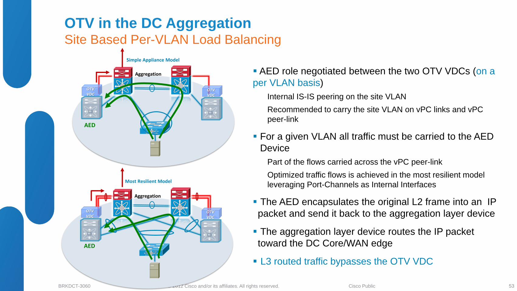
AED role negotiated between the two OTV VDCs (on a
per VLAN basis)
Internal IS-IS peering on the site VLAN
Recommended to carry the site VLAN on vPC links and vPC
peer-link
For a given VLAN all traffic must be carried to the AED
Device
Part of the flows carried across the vPC peer-link
Optimized traffic flows is achieved in the most resilient model
leveraging Port-Channels as Internal Interfaces
The AED encapsulates the original L2 frame into an IP
packet and send it back to the aggregation layer device
The aggregation layer device routes the IP packet
toward the DC Core/WAN edge
L3 routed traffic bypasses the OTV VDC
Most Resilient Model
Aggregation
Simple Appliance Model
OTV VDC
OTV VDC
AED
Aggregation
OTV VDC
OTV VDC
AED
OTV in the DC Aggregation Site Based Per-VLAN Load Balancing
53
© 2012 Cisco and/or its affiliates. All rights reserved. BRKDCT-3060 Cisco Public
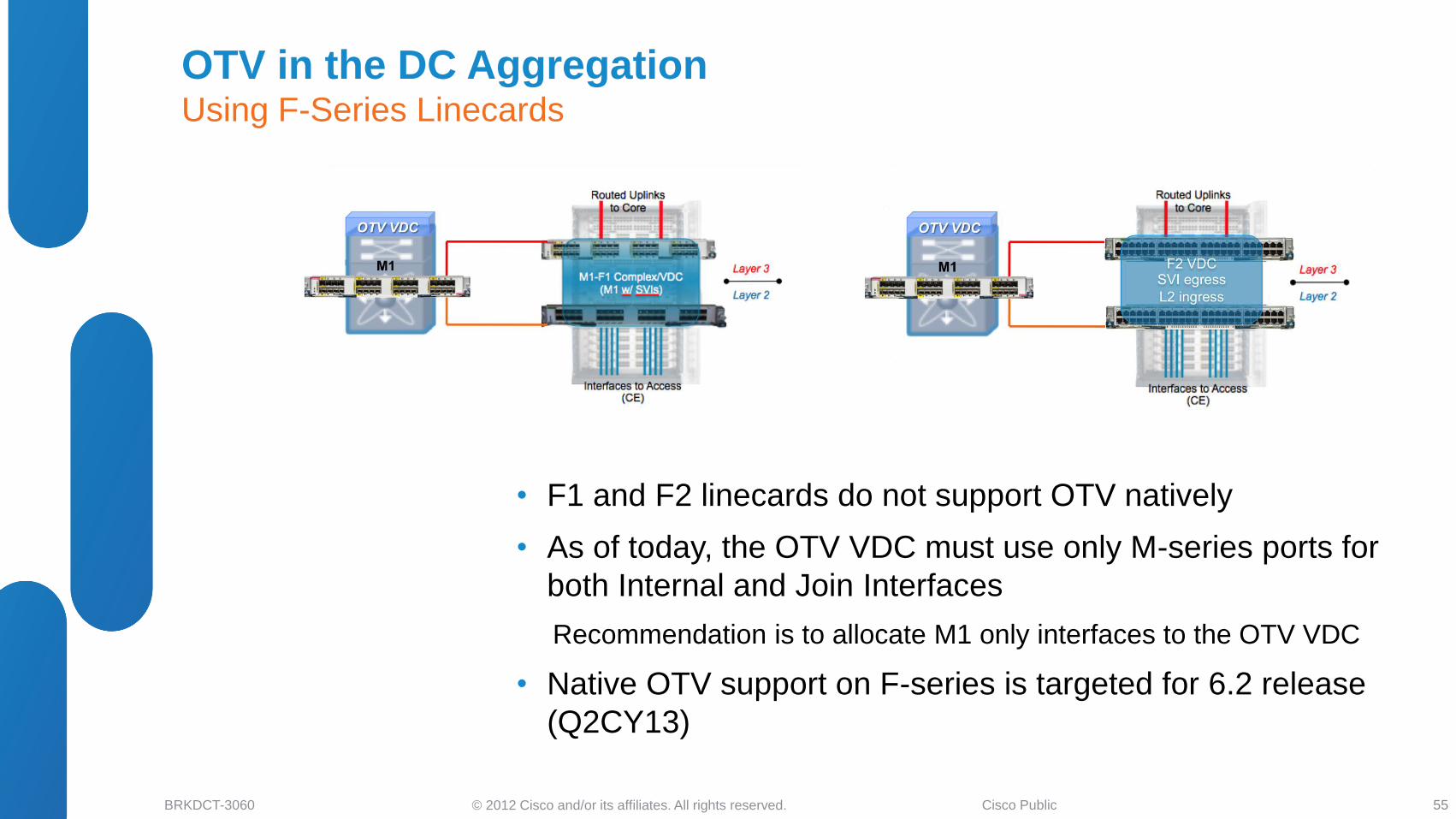
OTV in the DC Aggregation Using F-Series Linecards
55
• F1 and F2 linecards do not support OTV natively
• As of today, the OTV VDC must use only M-series ports for
both Internal and Join Interfaces
Recommendation is to allocate M1 only interfaces to the OTV VDC
• Native OTV support on F-series is targeted for 6.2 release
(Q2CY13)
© 2012 Cisco and/or its affiliates. All rights reserved. BRKDCT-3060 Cisco Public ** Could use static default route or ospf stub
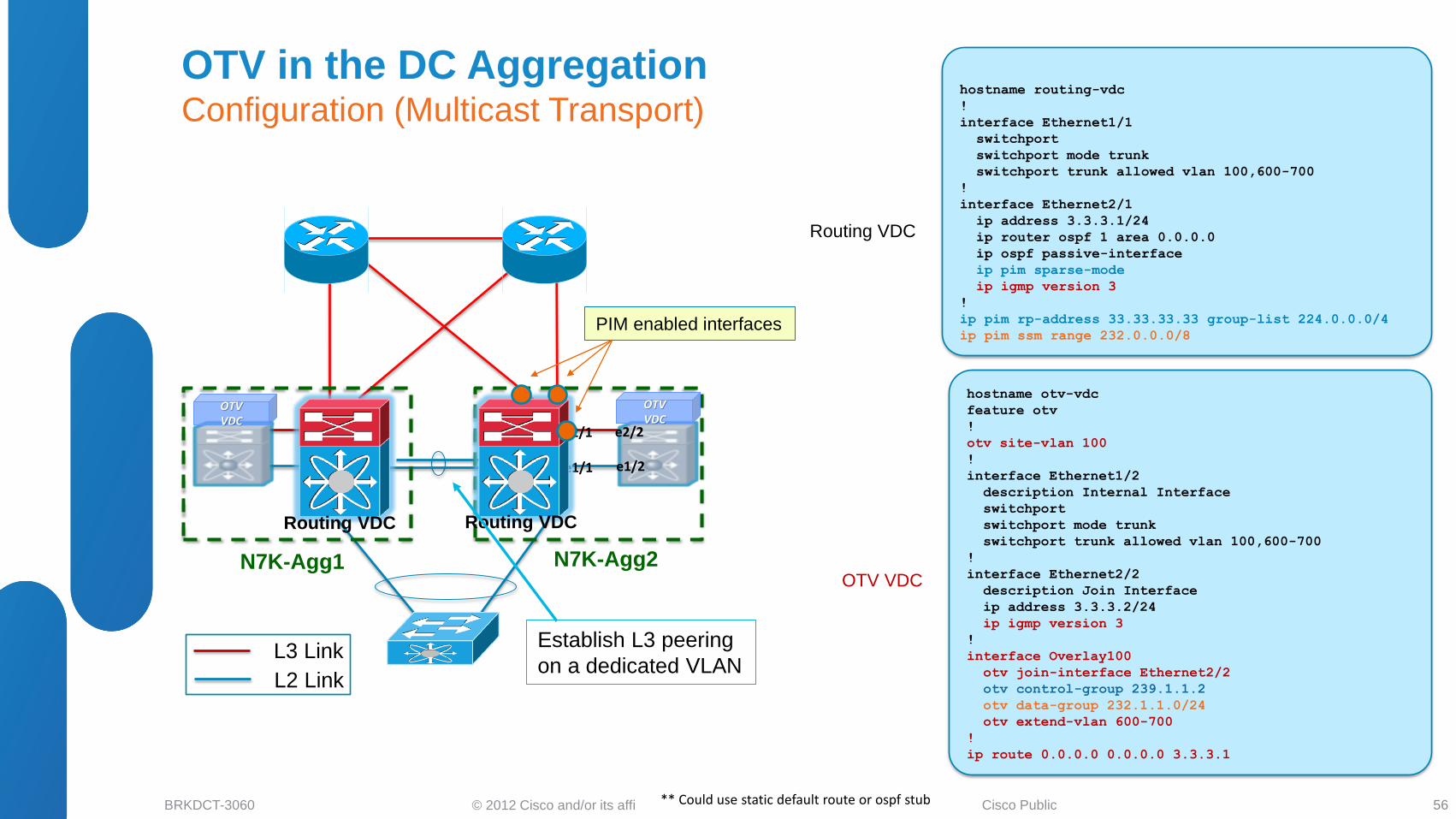
Routing VDC
OTV VDC
hostname routing-vdc
!
interface Ethernet1/1
switchport
switchport mode trunk
switchport trunk allowed vlan 100,600-700
!
interface Ethernet2/1
ip address 3.3.3.1/24
ip router ospf 1 area 0.0.0.0
ip ospf passive-interface
ip pim sparse-mode
ip igmp version 3
!
ip pim rp-address 33.33.33.33 group-list 224.0.0.0/4
ip pim ssm range 232.0.0.0/8
hostname otv-vdc
feature otv
!
otv site-vlan 100
!
interface Ethernet1/2
description Internal Interface
switchport
switchport mode trunk
switchport trunk allowed vlan 100,600-700
!
interface Ethernet2/2
description Join Interface
ip address 3.3.3.2/24
ip igmp version 3
!
interface Overlay100
otv join-interface Ethernet2/2
otv control-group 239.1.1.2
otv data-group 232.1.1.0/24
otv extend-vlan 600-700
!
ip route 0.0.0.0 0.0.0.0 3.3.3.1
N7K-Agg1 N7K-Agg2
e1/1 e1/2
e2/2 e2/1
L3 Link
L2 Link
Routing VDC Routing VDC
OTV VDC
OTV VDC
Establish L3 peering
on a dedicated VLAN
PIM enabled interfaces
OTV in the DC Aggregation Configuration (Multicast Transport)
56
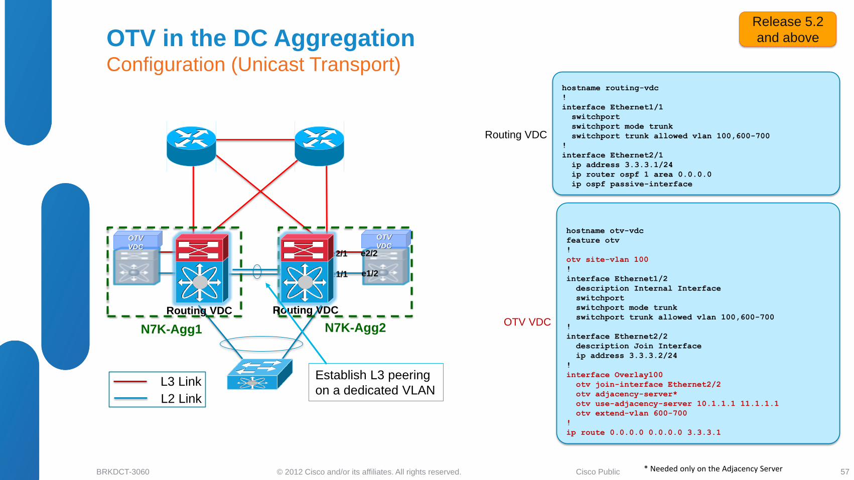
© 2012 Cisco and/or its affiliates. All rights reserved. BRKDCT-3060 Cisco Public
Routing VDC
OTV VDC
hostname routing-vdc
!
interface Ethernet1/1
switchport
switchport mode trunk
switchport trunk allowed vlan 100,600-700
!
interface Ethernet2/1
ip address 3.3.3.1/24
ip router ospf 1 area 0.0.0.0
ip ospf passive-interface
hostname otv-vdc
feature otv
!
otv site-vlan 100
!
interface Ethernet1/2
description Internal Interface
switchport
switchport mode trunk
switchport trunk allowed vlan 100,600-700
!
interface Ethernet2/2
description Join Interface
ip address 3.3.3.2/24
!
interface Overlay100
otv join-interface Ethernet2/2
otv adjacency-server*
otv use-adjacency-server 10.1.1.1 11.1.1.1
otv extend-vlan 600-700
!
ip route 0.0.0.0 0.0.0.0 3.3.3.1
N7K-Agg1 N7K-Agg2
e1/1 e1/2
e2/2 e2/1
L3 Link
L2 Link
Routing VDC Routing VDC
OTV
VDC
OTV
VDC
Establish L3 peering
on a dedicated VLAN
* Needed only on the Adjacency Server
Release 5.2
and above OTV in the DC Aggregation Configuration (Unicast Transport)
57
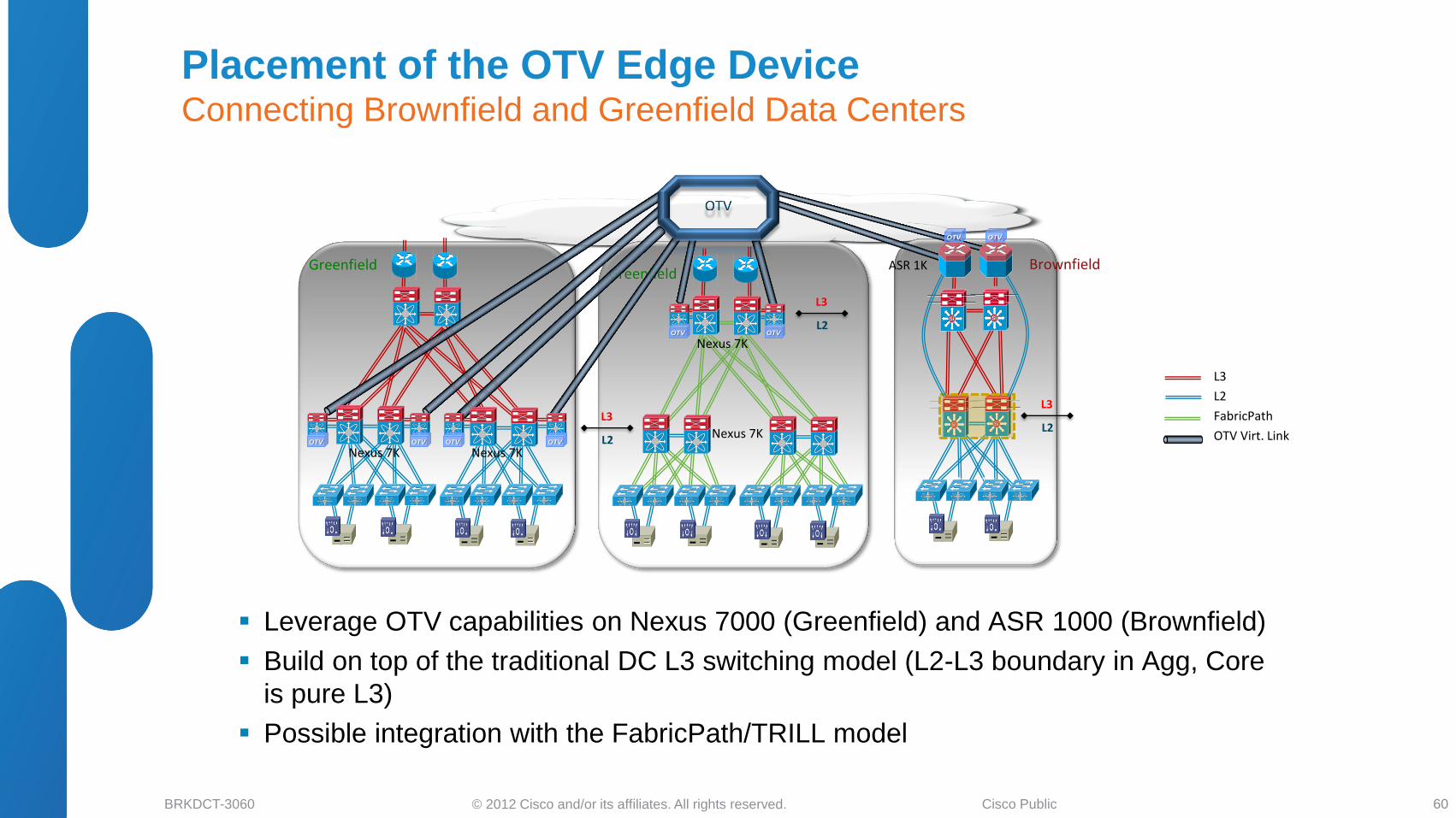
© 2012 Cisco and/or its affiliates. All rights reserved. BRKDCT-3060 Cisco Public
Brownfield
SiSi SiSi
SiSi
Leverage OTV capabilities on Nexus 7000 (Greenfield) and ASR 1000 (Brownfield)
Build on top of the traditional DC L3 switching model (L2-L3 boundary in Agg, Core
is pure L3)
Possible integration with the FabricPath/TRILL model
Greenfield
L3
L2
FabricPath
OTV Virt. Link
ASR 1K
Nexus 7K
SiSi
Greenfield
Nexus 7K
Nexus 7K L2
L3
L2
L3
L2
L3
Nexus 7K OTV OTV OTV OTV
OTV OTV
OTV OTV
Placement of the OTV Edge Device Connecting Brownfield and Greenfield Data Centers
60
© 2012 Cisco and/or its affiliates. All rights reserved. BRKDCT-3060 Cisco Public
6.2 (Q2CY13) OTV – New functionality
• Selective Unicast Flooding
(for unidirectional MACs & silent hosts)
• OTV VLAN translation
• Dedicated Data Broadcast Multicast Group
• Multiple Uplinks / Loopback ED IP
• Scalability to large deployment
• Fast convergence
‒ AED synchronization
‒ Fast remote convergence using Site-ID
‒ Fast local convergence using pre-population
‒ Fast ED failure detection using BFD & route tracking
• F1 and F2e as internal interfaces (proxy mode)
Key features for larger DCI usage
© 2012 Cisco and/or its affiliates. All rights reserved. BRKDCT-3060 Cisco Public
• DCI Business Drivers and Solutions Overview
• LAN Extension Deployment Scenarios
Ethernet Based Solutions
MPLS Based Solutions
IP Based Solutions
• LISP for DCI Deployments
LISP and Path Optimization
LISP as L3 DCI
• Summary and Q&A
Agenda
62
© 2012 Cisco and/or its affiliates. All rights reserved. BRKDCT-3060 Cisco Public
L2 Links (GE or 10GE)
L3 Links (GE or 10GE)
Layer 3 Core ISP A
ISP B
Access
Agg
Access
Agg
DC A DC B
VLAN A
Public Network
Data-Base Front-End
DB
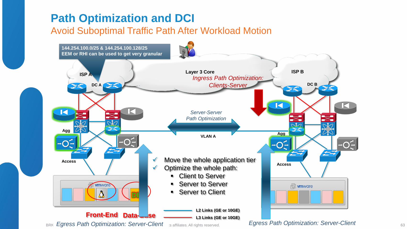
144.254.100.0/25 & 144.254.100.128/25
EEM or RHI can be used to get very granular
Move the whole application tier
Optimize the whole path:
Client to Server
Server to Server
Server to Client
Server-Server
Path Optimization
Egress Path Optimization: Server-Client Egress Path Optimization: Server-Client
Ingress Path Optimization:
Clients-Server
Path Optimization and DCI Avoid Suboptimal Traffic Path After Workload Motion
63
© 2012 Cisco and/or its affiliates. All rights reserved. BRKDCT-3060 Cisco Public
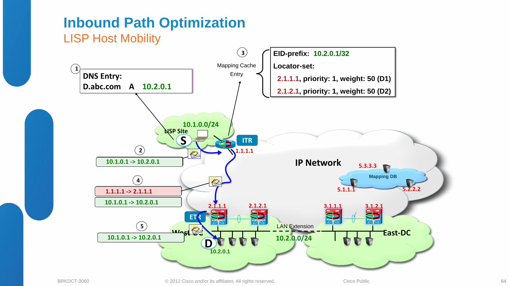
East-DC
LISP Site
IP Network
ETR
5.1.1.1
5.3.3.3
1.1.1.1
5.2.2.2
10.2.0.0/24 West-DC
10.1.0.0/24
ITR S
D
DNS Entry: D.abc.com A 10.2.0.1
1
10.1.0.1 -> 10.2.0.1
2
EID-prefix: 10.2.0.1/32
Locator-set:
2.1.1.1, priority: 1, weight: 50 (D1)
2.1.2.1, priority: 1, weight: 50 (D2)
Mapping Cache
Entry
3
10.1.0.1 -> 10.2.0.1
1.1.1.1 -> 2.1.1.1
4
10.1.0.1 -> 10.2.0.1
5
2.1.1.1 2.1.2.1 3.1.1.1 3.1.2.1
Mapping DB
Inbound Path Optimization LISP Host Mobility
64
LAN Extension
10.2.0.1
© 2012 Cisco and/or its affiliates. All rights reserved. BRKDCT-3060 Cisco Public
East-DC
LISP Site
IP Network
ETR
5.1.1.1
5.3.3.3
1.1.1.1
5.2.2.2
10.2.0.0/24 West-DC
10.1.0.0/24
ITR S
D
DNS Entry: D.abc.com A 10.2.0.1
EID-prefix: 10.2.0.1/32
Locator-set:
2.1.1.1, priority: 1, weight: 50 (D1)
2.1.2.1, priority: 1, weight: 50 (D2)
2.1.1.1 2.1.2.1 3.1.1.1 3.1.2.1
Mapping DB
Inbound Path Optimization LISP Host Mobility
65
LAN Extension
10.2.0.1
Workload Move
10.2.0.1
10.1.0.1 -> 10.2.0.1
1.1.1.1 -> 3.1.1.1
8
6
9
EID-prefix: 10.2.0.1/32
Locator-set:
3.1.1.1, priority: 1, weight: 50 (D1)
3.1.2.1, priority: 1, weight: 50 (D2)
Mapping Cache
Entry Update 7
© 2012 Cisco and/or its affiliates. All rights reserved. BRKDCT-3060 Cisco Public
• DCI Business Drivers and Solutions Overview
• LAN Extension Deployment Scenarios
Ethernet Based Solutions
MPLS Based Solutions
IP Based Solutions
• LISP for DCI Deployments
L3 Host Mobility using LISP
LISP as L3 DCI
• Summary and Conclusions
• Q&A
Agenda
67
© 2012 Cisco and/or its affiliates. All rights reserved. BRKDCT-3060 Cisco Public
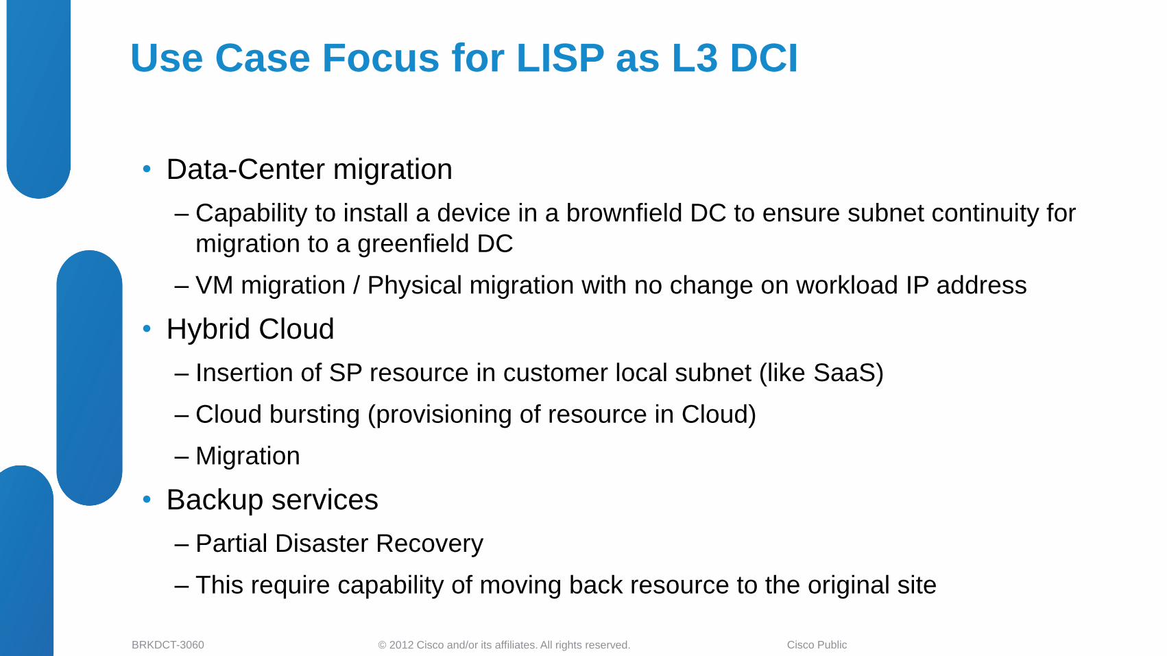
Use Case Focus for LISP as L3 DCI
• Data-Center migration
‒ Capability to install a device in a brownfield DC to ensure subnet continuity for
migration to a greenfield DC
‒ VM migration / Physical migration with no change on workload IP address
• Hybrid Cloud
‒ Insertion of SP resource in customer local subnet (like SaaS)
‒ Cloud bursting (provisioning of resource in Cloud)
‒ Migration
• Backup services
‒ Partial Disaster Recovery
‒ This require capability of moving back resource to the original site
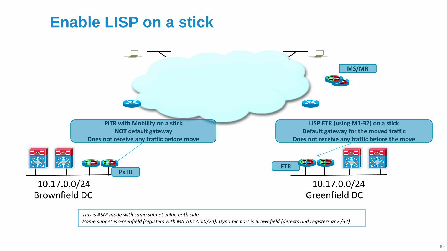
ETR
MS/MR
PiTR with Mobility on a stick NOT default gateway
Does not receive any traffic before move
Brownfield DC Greenfield DC 10.17.0.0/24 10.17.0.0/24
This is ASM mode with same subnet value both side Home subnet is Greenfield (registers with MS 10.17.0.0/24), Dynamic part is Brownfield (detects and registers any /32)
LISP ETR (using M1-32) on a stick Default gateway for the moved traffic
Does not receive any traffic before the move
PxTR
Enable LISP on a stick
69
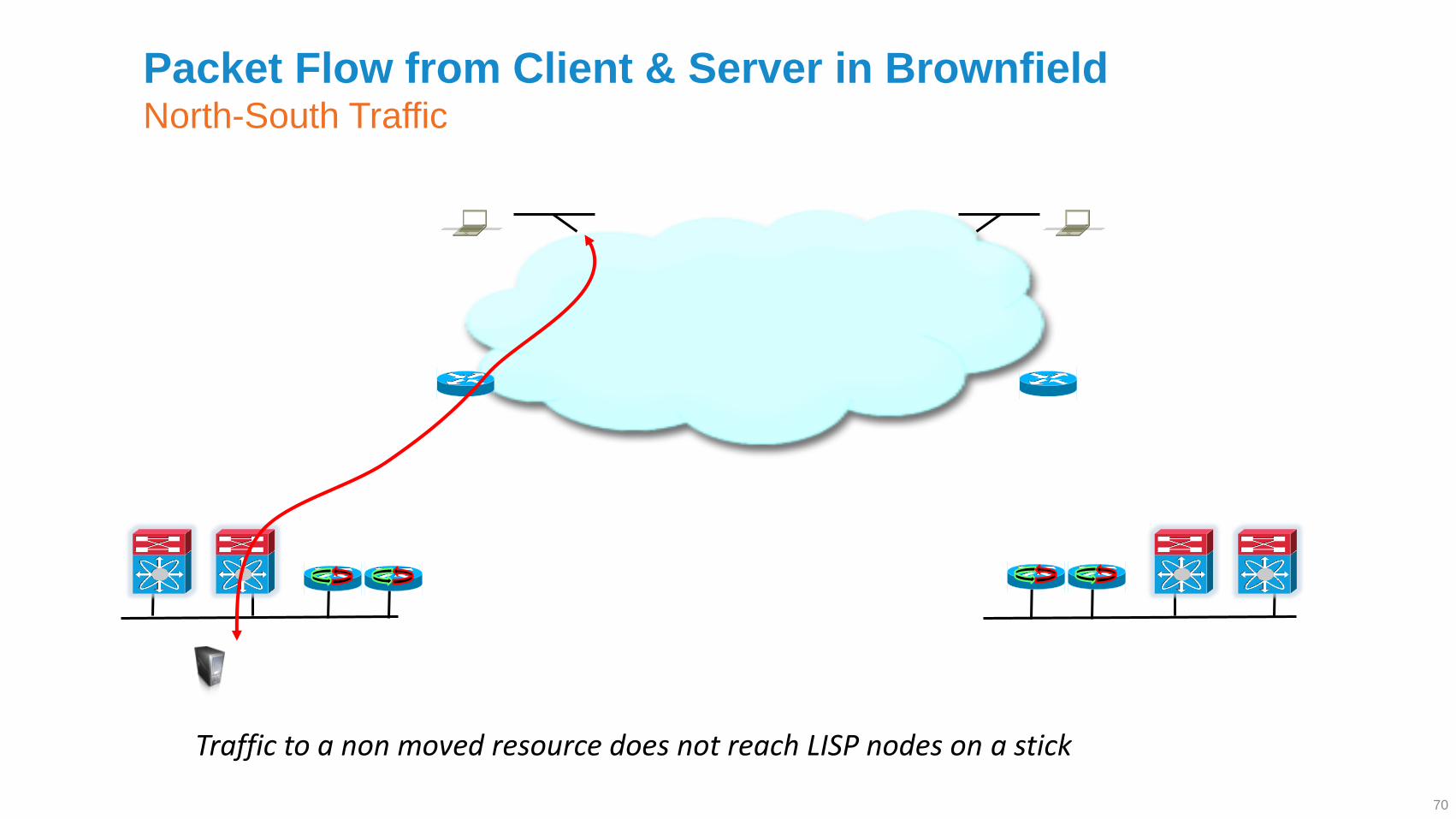
Packet Flow from Client & Server in Brownfield North-South Traffic
Traffic to a non moved resource does not reach LISP nodes on a stick
70
Symmetric Packet Flow from Client & Server in Greenfield North-South Traffic
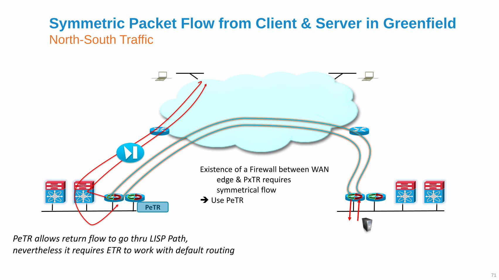
Existence of a Firewall between WAN edge & PxTR requires symmetrical flow
Use PeTR
PeTR allows return flow to go thru LISP Path, nevertheless it requires ETR to work with default routing
PeTR
71
© 2012 Cisco and/or its affiliates. All rights reserved. BRKDCT-3060 Cisco Public
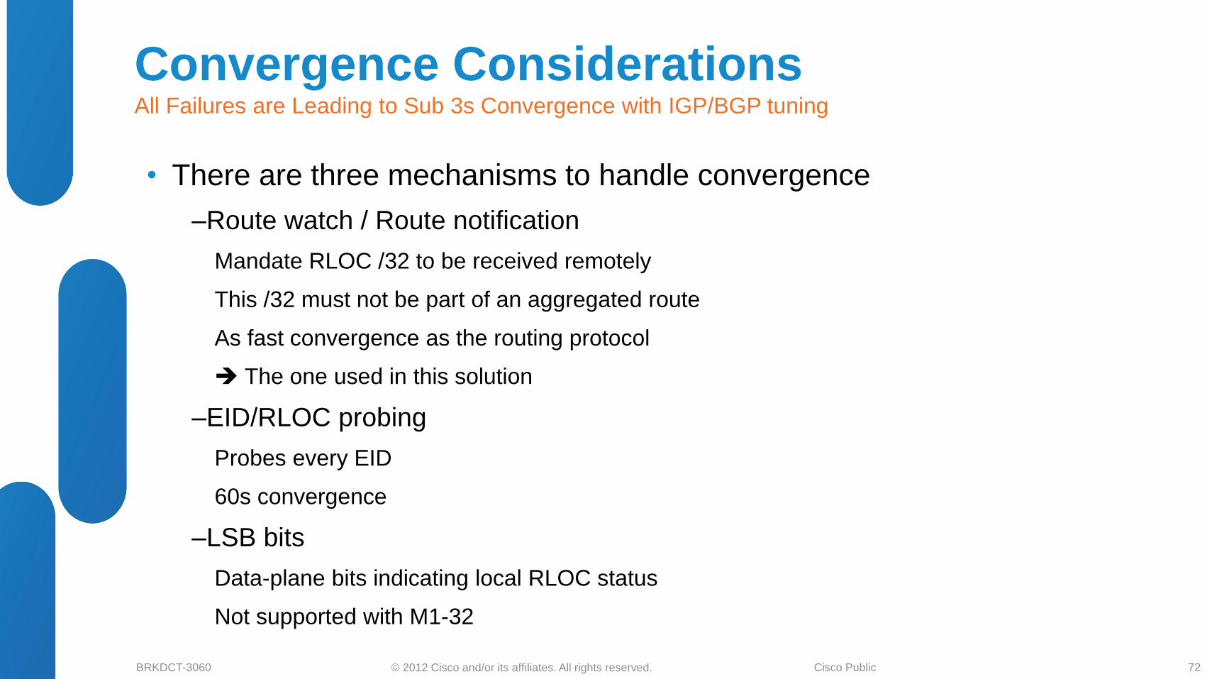
• There are three mechanisms to handle convergence
‒Route watch / Route notification
Mandate RLOC /32 to be received remotely
This /32 must not be part of an aggregated route
As fast convergence as the routing protocol
The one used in this solution
‒EID/RLOC probing
Probes every EID
60s convergence
‒LSB bits
Data-plane bits indicating local RLOC status
Not supported with M1-32
Convergence Considerations All Failures are Leading to Sub 3s Convergence with IGP/BGP tuning
72
© 2012 Cisco and/or its affiliates. All rights reserved. BRKDCT-3060 Cisco Public
• DCI Business Drivers and Solutions Overview
• LAN Extension Deployment Scenarios
Ethernet Based Solutions
MPLS Based Solutions
IP Based Solutions
• LISP for DCI Deployments
L3 Host Mobility using LISP
LISP as L3 DCI
• Summary and Q&A
Agenda
73
© 2012 Cisco and/or its affiliates. All rights reserved. BRKDCT-3060 Cisco Public
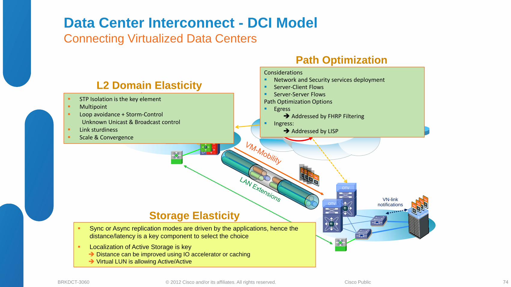
Data Center Interconnect - DCI Model Connecting Virtualized Data Centers
74
L2 Domain Elasticity - LAN Extension
VN-link notifications
Path Optimization - Optimal Routing - Route Portability
Storage Elasticity - SAN Extensions
OTV
OTV
OTV
OTV
Sync or Async replication modes are driven by the applications, hence the
distance/latency is a key component to select the choice
Localization of Active Storage is key Distance can be improved using IO accelerator or caching
Virtual LUN is allowing Active/Active
STP Isolation is the key element Multipoint Loop avoidance + Storm-Control
Unknown Unicast & Broadcast control Link sturdiness Scale & Convergence
Considerations Network and Security services deployment Server-Client Flows Server-Server Flows Path Optimization Options Egress
Addressed by FHRP Filtering Ingress:
Addressed by LISP
© 2012 Cisco and/or its affiliates. All rights reserved. BRKDCT-3060 Cisco Public
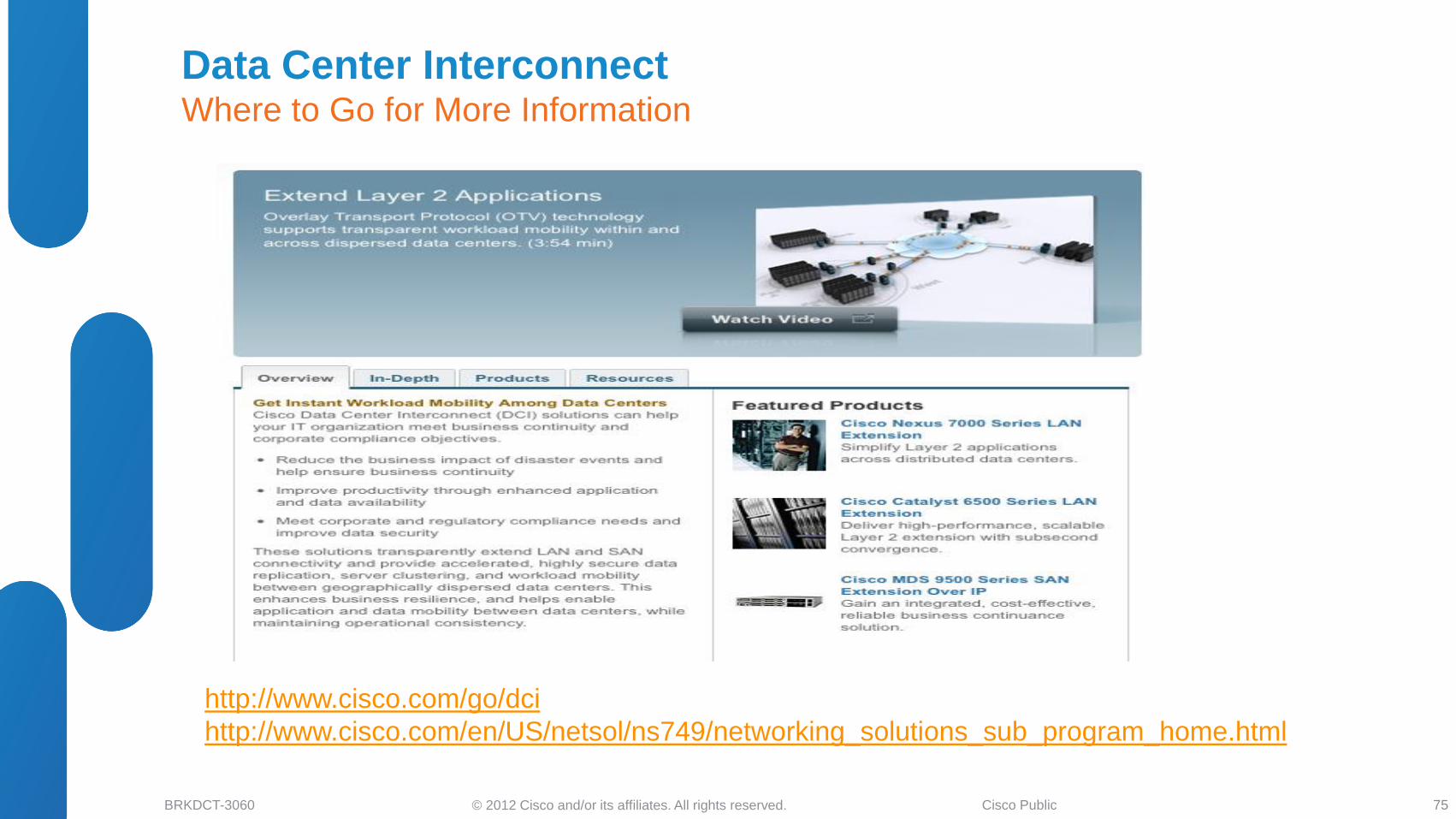
Data Center Interconnect Where to Go for More Information
75
http://www.cisco.com/go/dci
http://www.cisco.com/en/US/netsol/ns749/networking_solutions_sub_program_home.html
© 2012 Cisco and/or its affiliates. All rights reserved. BRKDCT-3060 Cisco Public
Recommended Reading for BRKDCT-3060
76 76 76
© 2012 Cisco and/or its affiliates. All rights reserved. BRKDCT-3060 Cisco Public
Call to Action
• Visit the Cisco Campus at the World of Solutions to experience Cisco innovations in action
• Get hands-on experience attending one of the Walk-in Labs
• Schedule face to face meeting with one of Cisco’s engineers
at the Meet the Engineer center
• Discuss your project’s challenges at the Technical Solutions Clinics
© 2012 Cisco and/or its affiliates. All rights reserved. BRKDCT-3060 Cisco Public