17
1 Dept Seminar: Jan 2007 Slide Turbulence Modelling for Aerospace January 2007 Alistair Revell
| Date post: | 20-Dec-2015 |
| Category: |
Documents |
| View: | 213 times |
| Download: | 0 times |

1Dept Seminar: Jan 2007 Slide
Turbulence Modelling for Aerospace
January 2007
Alistair Revell

2Dept Seminar: Jan 2007 Slide
Outline
• Review of EU Project work
• An Outline of recent research
• Derivation of a URANS model for stress-strain misalignment
• Application to industrial cases
• Future Work
• Further model development
• Application to aerospace
3Dept Seminar: Jan 2007 Slide
CFD in Aerospace: A comparison of methods
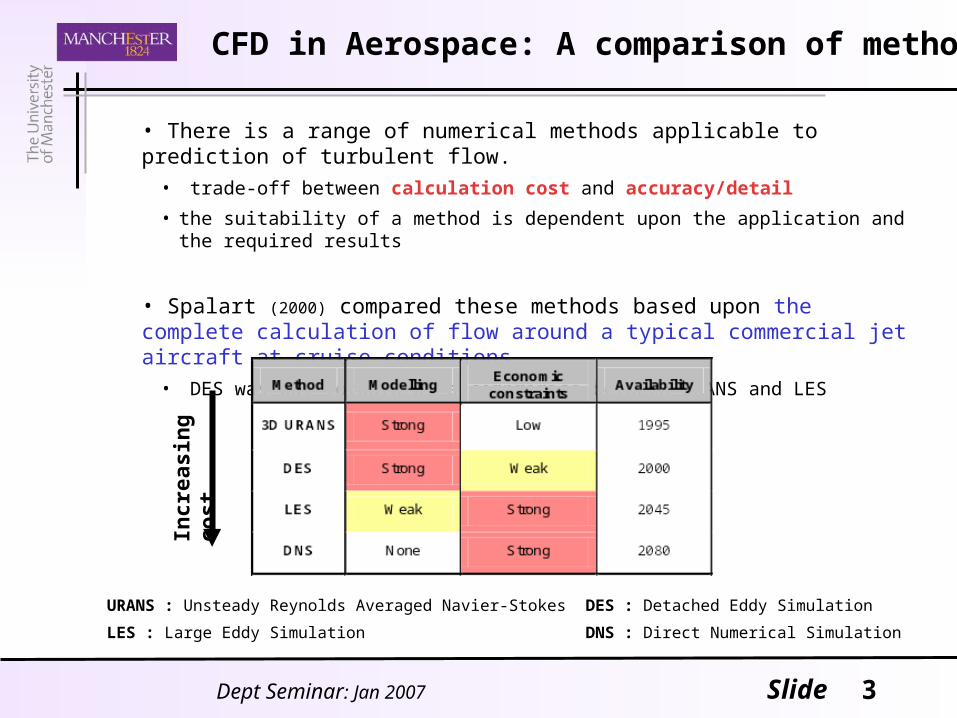
• There is a range of numerical methods applicable to prediction of turbulent flow.
• trade-off between calculation cost and accuracy/detail
• the suitability of a method is dependent upon the application and the required results
• Spalart (2000) compared these methods based upon the complete calculation of flow around a typical commercial jet aircraft at cruise conditions
• DES was put forward as a compromise between URANS and LES
URANS : Unsteady Reynolds Averaged Navier-Stokes DES : Detached Eddy Simulation
LES : Large Eddy Simulation DNS : Direct Numerical Simulation
Incr
easi
ng
co
st

4Dept Seminar: Jan 2007 Slide
Detached Eddy Simulation for Industrial Aerodynamics
• Previous EU project, FLOMANIA (2002-04), attempted to identify if any one turbulence modelling scheme was capable of tackling the range of challenges in an industrial case. (separation, reattachment, vortex shedding)
• DESider (2004-07), has looked at improved URANS and hybrid LES-RANS approaches. • Aims to overcome deficiencies in RANS whilst retaining realistic computational requirements.
• Objectives include:• Improved URANS modelling• Improved and standardised DES• Novel approaches (eg. SAS, Hybrid RANS-LES) • Embedded LES-RANS (inlet methods)
Involved in all activities
- the answer was NO
5Dept Seminar: Jan 2007 Slide
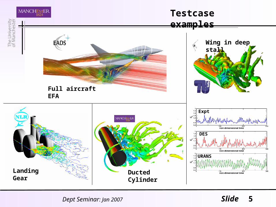
Testcase examples
Landing Gear
Full aircraft EFA
DES
Expt
URANS
Wing in deep stall
Ducted Cylinder

6Dept Seminar: Jan 2007 Slide
Derivation of new 3-equation model: SST-Cas
Increasing complexity
1 eqn.
Eg. Spalart Almaras
2 eqns.
Eg. k-
kSST
7 eqns.
RSM
uiuj -
3 eqns.
SST-Cas
• The parameter, Cas, provides a measure of the misalignment of the tensors of stress anisotropy, and strain, (Revell, Craft, Laurence 2006)
• New SST-Cas model reproduces some effects of the Reynolds Stress Model (RSM)
Objective: develop a turbulence model for industry that is able to accurately predict transient flow effects without compromising cost and stability
• Reynolds Averaged Navier Stokes equations are unclosed; require turbulence models
• Turbulent models predict evolution of one or more quantities in order to approximate the Reynolds Stresses (- ) or the turbulent viscosity ( )
7Dept Seminar: Jan 2007 Slide
Advantages of SST-Cas model
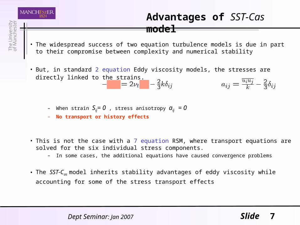
• The widespread success of two equation turbulence models is due in part to their compromise between complexity and numerical stability
• But, in standard 2 equation Eddy viscosity models, the stresses are directly linked to the strains.
– When strain Sij= 0 , stress anisotropy aij = 0 – No transport or history effects
• This is not the case with a 7 equation RSM, where transport equations are solved for the six individual stress components.
– In some cases, the additional equations have caused convergence problems
• The SST-Cas model inherits stability advantages of eddy viscosity while accounting for some of the
stress transport effects

8Dept Seminar: Jan 2007 Slide
• The misalignment parameter is defined as:
Which will be zero when aij and Sij are mutually perpendicular (for 2D)
• Where the implemented form of the transport equation is:
• Which fits easily into the SST implementation with a modification of viscosity as:
Implementation in Code_Saturne

9Dept Seminar: Jan 2007 Slide
Implementation of SST_Cas model
• Model implemented into Code_Saturne
- 3D unstructured finite volume code
• Validated for simple 1D and 2D unsteady flows:
- homogenous cyclic strain, oscillating channel
• extra equation found to add a 10-15% cost compared to a 2-equation model .
- RSM is around 80-100% more expensive than a 2-equation model
– Flowfield around NACA0012 at 20o, Re= 105
– Contour plots of long-time averaged Pressure with mean flow streamlines
(2-eqns) (3-eqns) (7-eqns)
• Reproduces similar results to RSM:

10Dept Seminar: Jan 2007 Slide
NACA0012 @ 20o
1 2 3
12 3
• Phase averaged velocity profiles <U>
• Good agreement of SST_Cas with RSM (SSG)
• Unsteady flow in wake of aerofoil:
misalignment of stress and strain is shown by eigenvectors, and elements are coloured by values of Cas

11Dept Seminar: Jan 2007 Slide
Cylinder in Square Duct
Experimental setup showing location of PIV data planes
• work done at IMFT
• Re = 1.4x10⁶
• 3D Calculations with ~2x10⁶ cells, where long-time averaged solutions obtained after:
e.g. 5.6 ~ 2 weeks calculation on 16 processors

12Dept Seminar: Jan 2007 Slide
Cylinder in Square Duct
SST
SST-Cas
SST-DES
Streamlines Iso-Q contours
• In Streamlines and <U>, top half is experimental data: bottom half is numerical results
• ‘Q’ criterion: a parameter used to visualise structures in the flow = (Sij2-ij
2)
<U>
13Dept Seminar: Jan 2007 Slide
Wingtip VortexCTR Summer Program 2006
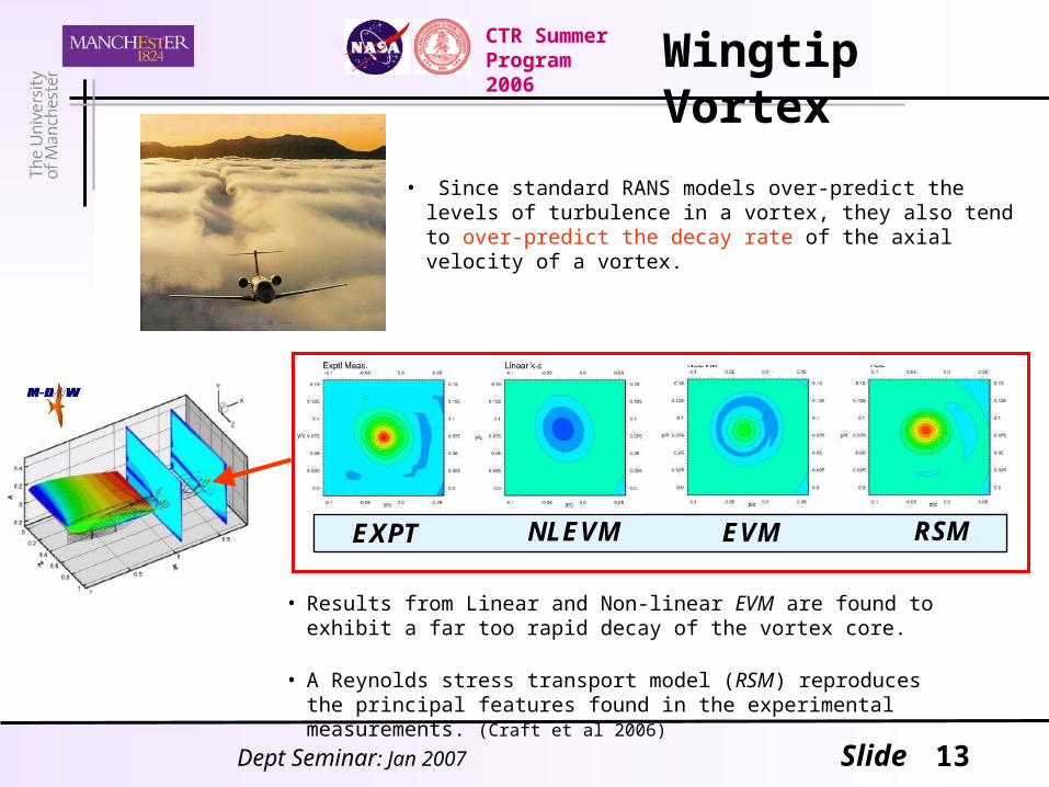
• Since standard RANS models over-predict the levels of turbulence in a vortex, they also tend to over-predict the decay rate of the axial velocity of a vortex.
EXPT NLEVM RSMEVMEXPT NLEVM RSMEVM
• Results from Linear and Non-linear EVM are found to exhibit a far too rapid decay of the vortex core.
• A Reynolds stress transport model (RSM) reproduces the principal features found in the experimental measurements. (Craft et al 2006)
14Dept Seminar: Jan 2007 Slide
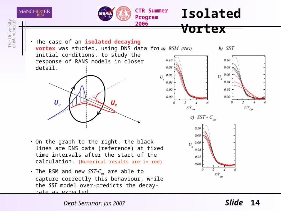
Isolated Vortex
• The case of an isolated decaying vortex was studied, using DNS data for initial conditions, to study the response of RANS models in closer detail.
CTR Summer Program 2006
U Ux
• On the graph to the right, the black lines are DNS data (reference) at fixed time intervals after the start of the calculation. (Numerical results are in red)
• The RSM and new SST-Cas are able to capture correctly this behaviour, while the SST model over-predicts the decay-rate as expected.
15Dept Seminar: Jan 2007 Slide
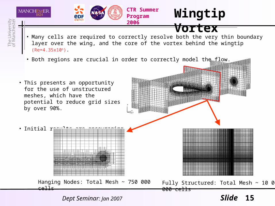
• This presents an opportunity for the use of unstructured meshes, which have the potential to reduce grid sizes by over 90%.
• Initial results are encouraging
Wingtip VortexCTR Summer Program 2006
Hanging Nodes: Total Mesh ~ 750 000 cells Fully Structured: Total Mesh ~ 10 000 000 cells
• Many cells are required to correctly resolve both the very thin boundary layer over the wing, and the core of the vortex behind the wingtip (Re=4.35x10⁶).
• Both regions are crucial in order to correctly model the flow.

17Dept Seminar: Jan 2007 Slide
Conclusions 1
• Equation derived to allow for stress-strain misalignment in URANS– Only solving 3 equations– Only small additional expense compared to EVM (additional ~15%)
• Remains ~40% cheaper than a full RSM
– Retains stability advantages of eddy viscosity over individual stress components.
• Fully implemented into Code_Saturne– Good practise is to start the SST-Cas calculation from a converged SST flow field.
• Further work– The possibility to use the SST-Cas model in a Detached Eddy Simulation (DES) framework
should be explored
– Development required for near-wall effects
– Investigate inclusion of Reynolds stresses in momentum eqn.• Secondary flow effects
18Dept Seminar: Jan 2007 Slide
Conclusions 2
• Code_Saturne is now an open source code– University of Manchester will aim to become the hub for development
• We will benefit from the implementation of further capabilities from 3rd parties
– New version has ‘Chimera’ moving-grid feature• allowing for calculation of Fluid-Structure Interactions
• Aerospace applications– Ongoing work on wingtip vortex (paper for TSFP5)
– Transient calculations can be used to study aeroacoustics • Investigate noise reduction e.g. jagged flap edges, casing around landing gear, cavities
– Develop cross-discipline topics in aerospace areas• Fluid-Structure interactions: eq. aeroelasticity• Combustion in complex cases: eg. Entire jet engine flow
– Drag reduction calculations can examine effect of bumps, grooves, dimples…• Unstructured code used to tackle complex geometries.


