IEEE TRANSACTIONS ON MAGNETICS, VOL. 38, NO. 2, MARCH 2002 1125
Derivation of a General Sensitivity Formula forShape Optimization of 2-D Magnetostatic
Systems by Continuum ApproachDong-Hun Kim, Se-Hee Lee, Il-Han Park, and Joon-Ho Lee
Abstract—This paper presents a generalized sensitivity formulathat is applicable to any objective function of the optimizationproblems in two-dimensional (2-D) linear magnetostatic systems.For the objective function defined on an interface boundary as wellas in a region, the shape design sensitivity expression is derivedin a closed form from the augmented Lagrangian method, thematerial derivative concept and the adjoint variable method. Theresultant sensitivity formula is expressed as a line integral alongthe interface boundary undergoing shape modification. Threeshape design problems, whose objective functions are defined onan interface boundary or in a region, are tested to validate thederived sensitivity formula.
I N CONJUNCTION with the numerical analysis methods,the shape design sensitivity analysis reported in [1]–[5]
has been successfully applied to some optimization problemsin magnetostatic systems for about last ten years. Two mainapproaches have emerged for the design sensitivity analysis: thediscrete approach and the continuum approach. In the discreteapproach [1]–[3], the sensitivity information is calculated fromdirect differentiation of discretized system equation by FEMor BEM. In the continuum approach [4], the design sensitivityis evaluated by using an analytical formula with numericalsolutions of the primary system and its corresponding adjointsystem. The two approaches lead to different implementationsfor numerical calculations.
In the viewpoint of numerical implementation, the continuumapproach has been proved easier and more efficient than the dis-crete one in the papers [4], [5]. It permits modular programmingfor an analysis part and a design one and its analytical sensitivityformula can be used regardless of numerical analysis methods.Thus, the continuum approach has been attractive to the areas ofthe CAD and CAE even though it is not easy to derive the analyt-ical sensitivity expression for a functional of the state variables.
However, until now, no steady research has been carried out onthecontinuumapproachandonlyafewarticlesdealtwith it for theoptimal design of two-dimensional (2-D) magnetostatic devices.Theanalyticalsensitivityformuladerivedinthepreviouswork[4]
Manuscript received July 5, 2001; revised October 25, 2001.The authors are with the School of Electrical and Computer Engi-
hasbeen limited to the objective functions thataredefined only inaregion.Therefore, this formulacannotcover theshapeoptimiza-tion problems related to the physical quantities on any interfaceboundary between different materials.
In this paper, the continuum sensitivity formula is generalizedto be applicable to any optimization problems in 2-D magneto-static systems. For the objective function defined on an inter-face boundary or in a region, the design sensitivity expressionis derived in a closed form from the governing variational equa-tion by using the augmented Lagrangian method, the materialderivative concept, and the adjoint variable method. The resul-tant sensitivity formula is expressed in a line integral form alongthe interface boundary undergoing shape modification. Usingthis sensitivity formula, we can deal with the shape optimiza-tion problems to directly control the physical quantities on theinterface such as magnetic field and force density.
II. COMPLETE SENSITIVITY FORMULA
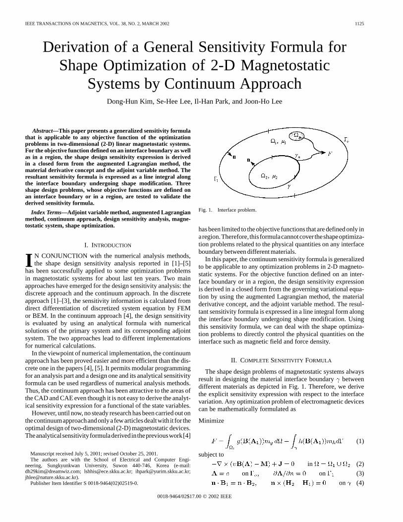
The shape design problems of magnetostatic systems alwaysresult in designing the material interface boundarybetweendifferent materials as depicted in Fig. 1. Therefore, we derivethe explicit sensitivity expression with respect to the interfacevariation. Any optimization problem of electromagnetic devicescan be mathematically formulated as
1126 IEEE TRANSACTIONS ON MAGNETICS, VOL. 38, NO. 2, MARCH 2002
where is the magnetic reluctivity, the permanent magneti-zation, the current density, and the subscripts, 1 and 2, meanthe corresponding regions and , respectively. To expandthe existing sensitivity formula of [4] to a general form, the ob-jective function is written as the sum of the area and the lineintegrals of (1) where and are arbitrary functions differen-tiable to , respectively. The characteristic functionsand in (1) denote the parts of the regionand the interface
on which the objective functions are defined. The state vari-able must satisfy the state equation (2) of the primary system,the boundary conditions (3) and the interface boundary condi-tions (4). Since the objective function is normally nonlinear andimplicit function to design variables, the augmented Lagrangianmethod is used as a nonlinear programming method. The vari-ational equation including the equality constraints (2) with (3)and (4) is multiplied by the Lagrange multiplier vectorand isadded to the objective function (1). Then, the augmented objec-tive function is established as
(5)
where the superscript and the subscriptdenote the transposeand the tangential component of a vector, respectively. The in-tegral path on the right-hand side of (5) is comprised of theinterface boundary and the outer boundaries and .
To obtain the variation of (5) with respect to design variables,we decompose the integrals overor into those over thecorresponding subdomain or segment and then take the materialderivative of continuum mechanics [4], [5] on both sides. Afterthese manipulations, (5) is rewritten as follows:
(6)
where , , is the ma-terial derivative of the state variable, the mean curvature,
and the normal component of the design velocity field.The integral terms related to in (6) vanish by substitutingfor the variable in the variational form of the primary systemthat is included in (5).
To obtain the explicit expression of (6) with respect to thedesign velocity field, an adjoint variable method is introduced.The variational equation of the adjoint system corresponding tothe primary system is defined as the integral terms related to the
in (6).
for all (7)
where means admissible space of the state variable and theLagrange multiplier is interpreted as the adjoint variable as-sociated with the state variable of the primary system. From (7),the adjoint variable equation and its boundary conditions can bededuced in the following point form:
in (8)
on on (9)
on (10)
where and represent the applied loads in theadjoint system related to the first and the second integral termsof the objective function (1), respectively. In contradistinctionto [4], the additional load comes from the function definedon the interface and results in discontinuity of the tangen-tial component of the adjoint field in the adjoint system.The Lagrange multiplier referred to as the adjoint variableis obtained by solving the adjoint system equation (8) with itsboundary conditions (9) and interface conditions (10).
For the analytical sensitivity expression for the objectivefunction, the area integrals in (6) are converted into boundaryintegrals and are coupled to the interface boundary conditions.After these manipulations, (6) is simplified as the integration ofthe state and adjoint variables only along the movable interfaceand we can finally obtain the complete sensitivity formula as
(11)
The last two terms in square brackets in (11) contribute tothe derivative of the objective function only when the objectivefunction, and the design variables are defined on the same partof the interface .
III. N UMERICAL EXAMPLES
To validate the derived sensitivity formula (11), three kindsof the optimal shape design problems to control the magneticforce density on the interface boundary are tested. In this paper,the magnetic force density is computed by the magnetic chargemethod presented in [6]. The steepest descent method of the op-timization techniques is employed for the search direction andthe step-size. The piece-wise linear parametrization is utilized
KIM et al.: DERIVATION OF A GENERAL SENSITIVITY FORMULA FOR SHAPE OPTIMIZATION 1127
Fig. 2. Design model of two parallel iron plates.
to avoid numerical errors by the possible sawtooth shape of in-terface boundary.
A. Objective Function Only on an Interface
Two parallel iron plates are located in a uniform field andtheir specifications are shown in Fig. 2. The design objective isto obtain a plate shape along the line A that provides a uniformdistribution of magnetic force density on lines A and B. Theobjective function is expressed as follows:
(12)
where is the normal component of the force density vectorat the th iteration and means the target value of 700 kN/mthat is taken to be smaller by 30% than the initial one. We canconsider two probable design problems of case I and case II thatare classified according as the objective function and the designvariables are defined on the same line or not.
1) Case I: Both of the objective function and the design vari-ables are defined on line A. In this case, the first and the lasttwo terms in square brackets of (11) contribute to the sensitivitycoefficients. After 35 iterations, the objective function (12) con-verges within 3% difference to the target value. It is assumed thata little slow convergence comes from the fact that the integralpath of the objective function successively changes in each iter-ative design process. Fig. 3 shows the final shapes and the forcedensity vectors after the optimization. We can see in Fig. 4 thatthe magnetic force densities along line A are compared with theinitial and the target values.
2) Case II: On the other hand, in case II, the objective func-tion is defined on the line B and the design variables are on theline A. In this case, only the first term in square brackets of (11)contributes to the derivative of the objective function and onlysix iterations are required to get an optimal shape of the plate.Figs. 5 and 6 show the final shapes, the force density vectorsand the comparison of the magnetic force densities along theline B. It is considered that the change of the integral path of theobjective function in case I brings about the quite different re-sults between two cases even though they have same integrandas (12).
Fig. 3. Final shapes and force density vectors after optimization.
Fig. 4. Comparison of force densities before and after optimization.
Fig. 5. Final shapes and force density vectors after optimization.
B. Objective Function on Both an Interface and a Region
Let us consider an electromagnet that consists of an iron yokeand a plate with an air gap of 5 mm and is driven with a directcurrent source. Its half model is depicted in Fig. 7. Here, we in-tend to deal with the multiobjective function expressed as thesum of the area and the line integrals like (1). The design ob-jective is to obtain a bottom shape of the yoke that provides a
1128 IEEE TRANSACTIONS ON MAGNETICS, VOL. 38, NO. 2, MARCH 2002
Fig. 6. Comparison of force densities before and after optimization.
Fig. 7. Design model of an electromagnet.
desired coil inductance as well as a uniform distribution of theforce density along the bold line on the plate as in Fig. 7. Theobjective function is expressed as follows:
(13)
where a weighing factor is taken to be 1000, is the coilinductance at theth iteration, and the target inductance of5.562 H that is smaller by 11% than the initial one. The coilinductance is calculated from the magnetic energy stored withinwhole space and the in (13) is set to 8512 N/mthat issmaller by 45% than the initial one.
After about seven iterations, the coil inductance and the forcedensity converge to the target values within 0.8% and 5% dif-ference, respectively. The yoke shapes and the magnetic forcedensity distributions before and after the optimization are com-pared in Figs. 8 and 9, respectively.
IV. CONCLUSION
The analytic sensitivity formula of (13), which can be appli-cable to any objective function, was successfully derived in the
Fig. 8. Yoke shapes before and after optimization.
Fig. 9. Comparison of force densities before and after optimization.
line integral form of the functions of the state and the adjointvariables. The numerical results of three test models showedvalidity of the proposed shape design sensitivity analysis. It isexpected that this continuum sensitivity formula can be widelyemployed for the shape design optimization problems in 2-Dmagnetostatic systems.
REFERENCES
[1] J. A. Ramirez and E. M. Freeman, “The direct calculation of global quan-tities from an FE formulation for the optimization of power frequencyelectromagnetic devices,”IEEE Trans. Magn., vol. 34, pp. 2881–2884,Sept. 1998.
[2] J. M. Biedinger and D. Leamoine, “Shape sensitivity analysis of mag-netic forces,”IEEE Trans. Magn., vol. 33, pp. 2309–2316, May 1997.
[3] C.-S. Koh, S.-Y. Hahn, K.-S. Lee, and K. Choi, “Design sensitivityanalysis for shape optimization of 3-D electromagnetic devices,”IEEETrans. Magn., vol. 29, pp. 1753–1756, Mar. 1993.
[4] I.-h. Park, J. L. Coulomb, and S.-y. Hahn, “Implementation of con-tinuum sensitivity analysis with existing finite element code,”IEEETrans. Magn., vol. 29, pp. 1787–1790, Mar. 1993.
[5] E. Hardeeet al., “A CAD-based design parameterization for shape opti-mization of elastic solids,”Adv. Eng. Softw., vol. 30, pp. 185–199, 1999.
[6] S.-H. Lee et al., “Comparison of mechanical deformations due todifferent force distributions of two equivalent magnetization models,”IEEE Trans. Magn., vol. 36, pp. 1368–1372, July 2000.