PT2272 V3.6 - 1 - Remote Control Decoder PT2272 DESCRIPTION PT2272 is a remote control decoder paired with PT2262 utilizing CMOS Technology. It has 12 bits of tri-state address pins providing a maximum of 531,441 (or 312) address codes; thereby, drastically reducing any code collision and unauthorized code scanning possibilities. PT2272 is available in several options to suit every application need: variable number of data output pins, latch or momentary output type. FEATURES • CMOS Technology • Low Power Consumption • Very High Noise Immunity • Up to 12 Tri-State Code Address Pins • Up to 6 Data Pins • Wide Range of Operating Voltage: VCC=4~15V • Single Resistor Oscillator • Latch or Momentary Output Type • Available in DIP and SOP APPLICATIONS • Car Security System • Garage Door Controller • Remote Control Fan • Home Security/Automation System • Remote Control Toys • Remote Control for Industrial Use WWW.AYXSJ.COM Tel: 86-372-5968708 Fax: 86-372-5968993 URL: http://www.ayxsj.com
Transcript
PT2272 V3.6 - 1 -
Remote Control Decoder PT2272
DESCRIPTION PT2272 is a remote control decoder paired with PT2262 utilizing CMOS Technology. It has 12 bits of tri-state address pins providing a maximum of 531,441 (or 312) address codes; thereby, drastically reducing any code collision and unauthorized code scanning possibilities. PT2272 is available in several options to suit every application need: variable number of data output pins, latch or momentary output type. FEATURES
• CMOS Technology • Low Power Consumption • Very High Noise Immunity • Up to 12 Tri-State Code Address Pins • Up to 6 Data Pins • Wide Range of Operating Voltage: VCC=4~15V • Single Resistor Oscillator • Latch or Momentary Output Type • Available in DIP and SOP
APPLICATIONS • Car Security System • Garage Door Controller • Remote Control Fan • Home Security/Automation System • Remote Control Toys • Remote Control for Industrial Use
WWW.AYXSJ.COM
Tel: 86-372-5968708 Fax: 86-372-5968993
URL: http://www.ayxsj.com
PT2272 V3.6 - 2 -
Remote Control Decoder PT2272
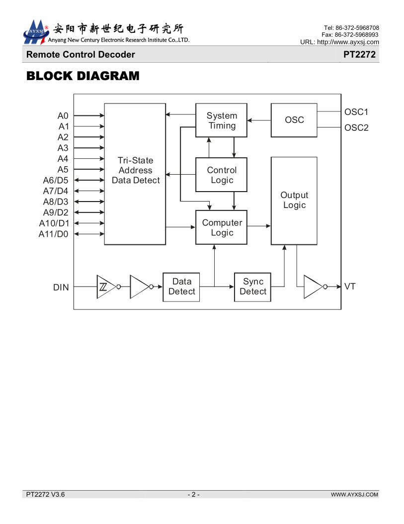
BLOCK DIAGRAM
Tri-StateAddress
Data Detect
A0A1A2A3A4A5
A6/D5A7/D4A8/D3A9/D2
A10/D1A11/D0
SystemTiming
Control Logic
ComputerLogic
OSC
OutputLogic
DataDetect
SyncDetect
OSC1
OSC2
VTDIN
WWW.AYXSJ.COM
Tel: 86-372-5968708 Fax: 86-372-5968993
URL: http://www.ayxsj.com
PT2272 V3.6 - 3 -
Remote Control Decoder PT2272
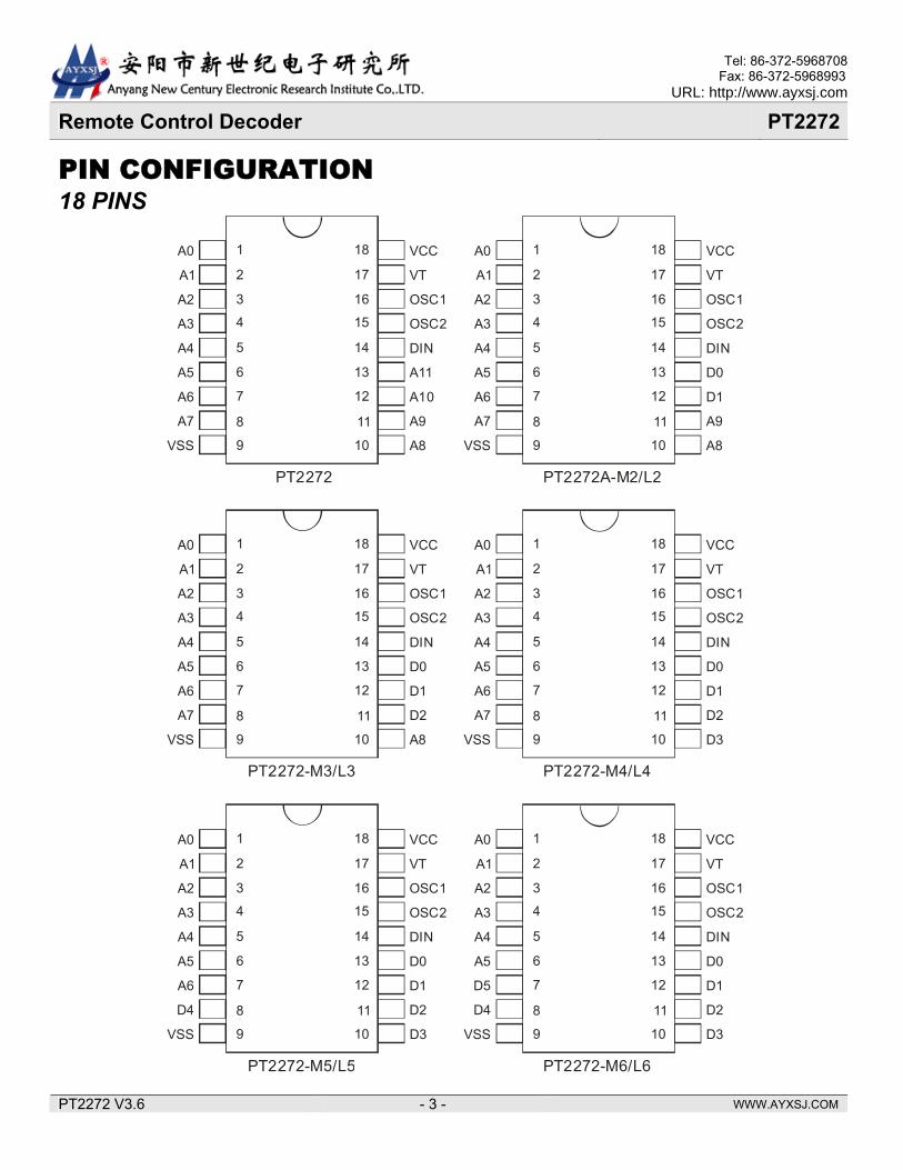
PIN CONFIGURATION 18 PINS
A0
A1
A2
A3
A4
A5
A6
A7
VCC
VT
OSC1
OSC2
DIN
A11
A10
A9
VSS A8
1
3
2
4
5
6
7
8
9
18
16
17
15
14
13
12
11
10
P 2272T
A0
A1
A2
A3
A4
A5
A6
A7
VCC
VT
OSC1
OSC2
DIN
D0
D1
A9
VSS A8
1
3
2
4
5
6
7
8
9
18
16
17
15
14
13
12
11
10
PT2272A-M2/L2
A0
A1
A2
A3
A4
A5
A6
A7
VCC
VT
OSC1
OSC2
DIN
D0
D1
D2
VSS A8
1
3
2
4
5
6
7
8
9
18
16
17
15
14
13
12
11
10
P 2272-M3/L3T
A0
A1
A2
A3
A4
A5
A6
A7
VCC
VT
OSC1
OSC2
DIN
D0
D1
D2
VSS D3
1
3
2
4
5
6
7
8
9
18
16
17
15
14
13
12
11
10
PT2272-M4/L4
A0
A1
A2
A3
A4
A5
A6
D4
VCC
VT
OSC1
OSC2
DIN
D0
D1
D2
VSS D3
1
3
2
4
5
6
7
8
9
18
16
17
15
14
13
12
11
10
P 2272-M5/L5T
A0
A1
A2
A3
A4
A5
D5
D4
VCC
VT
OSC1
OSC2
DIN
D0
D1
D2
VSS D3
1
3
2
4
5
6
7
8
9
18
16
17
15
14
13
12
11
10
PT2272-M6/L6
WWW.AYXSJ.COM
Tel: 86-372-5968708 Fax: 86-372-5968993
URL: http://www.ayxsj.com
PT2272 V3.6 - 4 -
Remote Control Decoder PT2272
20 PINS
A0
A1
A2
A3
A4
A5
A6
A7
VCC
VT
OSC1
OSC2
DIN
A11
A10
A9
VSS A8
1
3
2
4
5
6
7
8
9
20
18
19
17
16
15
14
13
12
P 2272T
NC NC10 11
A0
A1
A2
A3
A4
A5
A6
A7
VCC
VT
OSC1
OSC2
DIN
D0
D1
A9
VSS A8
1
3
2
4
5
6
7
8
9
20
18
19
17
16
15
14
13
12
P 2272A-M2/L2T
NC NC10 11
A0
A1
A2
A3
A4
A5
A6
A7
VCC
VT
OSC1
OSC2
DIN
D0
D1
D2
VSS A8
1
3
2
4
5
6
7
8
9
20
18
19
17
16
15
14
13
12
P 2272-M3/L3T
NC NC10 11
A0
A1
A2
A3
A4
A5
A6
A7
VCC
VT
OSC1
OSC2
DIN
D0
D1
D2
VSS D3
1
3
2
4
5
6
7
8
9
20
18
19
17
16
15
14
13
12
P 2272A-M4/L4T
NC NC10 11
A0
A1
A2
A3
A4
A5
A6
D4
VCC
VT
OSC1
OSC2
DIN
D0
D1
D2
VSS D3
1
3
2
4
5
6
7
8
9
20
18
19
17
16
15
14
13
12
P 2272-M5/L5T
NC NC10 11
A0
A1
A2
A3
A4
A5
D5
D4
VCC
VT
OSC1
OSC2
DIN
D0
D1
D2
VSS D3
1
3
2
4
5
6
7
8
9
20
18
19
17
16
15
14
13
12
P 2272A-M6/L6T
NC NC10 11
WWW.AYXSJ.COM
Tel: 86-372-5968708 Fax: 86-372-5968993
URL: http://www.ayxsj.com
PT2272 V3.6 - 5 -
Remote Control Decoder PT2272
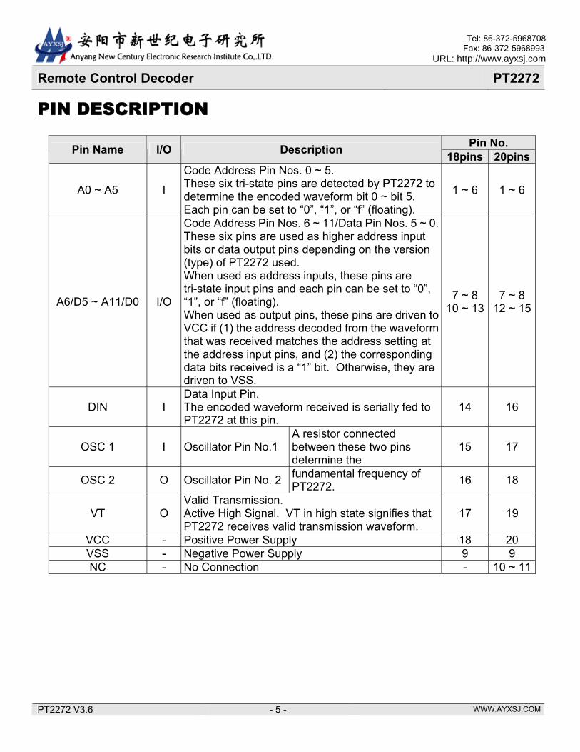
PIN DESCRIPTION
Pin No. Pin Name I/O Description 18pins 20pins
A0 ~ A5 I
Code Address Pin Nos. 0 ~ 5. These six tri-state pins are detected by PT2272 to determine the encoded waveform bit 0 ~ bit 5. Each pin can be set to “0”, “1”, or “f” (floating).
1 ~ 6 1 ~ 6
A6/D5 ~ A11/D0 I/O
Code Address Pin Nos. 6 ~ 11/Data Pin Nos. 5 ~ 0. These six pins are used as higher address input bits or data output pins depending on the version (type) of PT2272 used. When used as address inputs, these pins are tri-state input pins and each pin can be set to “0”, “1”, or “f” (floating). When used as output pins, these pins are driven to VCC if (1) the address decoded from the waveform that was received matches the address setting at the address input pins, and (2) the corresponding data bits received is a “1” bit. Otherwise, they are driven to VSS.
7 ~ 8 10 ~ 13
7 ~ 8 12 ~ 15
DIN I Data Input Pin. The encoded waveform received is serially fed to PT2272 at this pin.
14 16
OSC 1 I Oscillator Pin No.1 A resistor connected between these two pins determine the
15 17
OSC 2 O Oscillator Pin No. 2 fundamental frequency of PT2272. 16 18
VT O Valid Transmission. Active High Signal. VT in high state signifies that PT2272 receives valid transmission waveform.
17 19
VCC - Positive Power Supply 18 20 VSS - Negative Power Supply 9 9 NC - No Connection - 10 ~ 11
WWW.AYXSJ.COM
Tel: 86-372-5968708 Fax: 86-372-5968993
URL: http://www.ayxsj.com
PT2272 V3.6 - 6 -
Remote Control Decoder PT2272
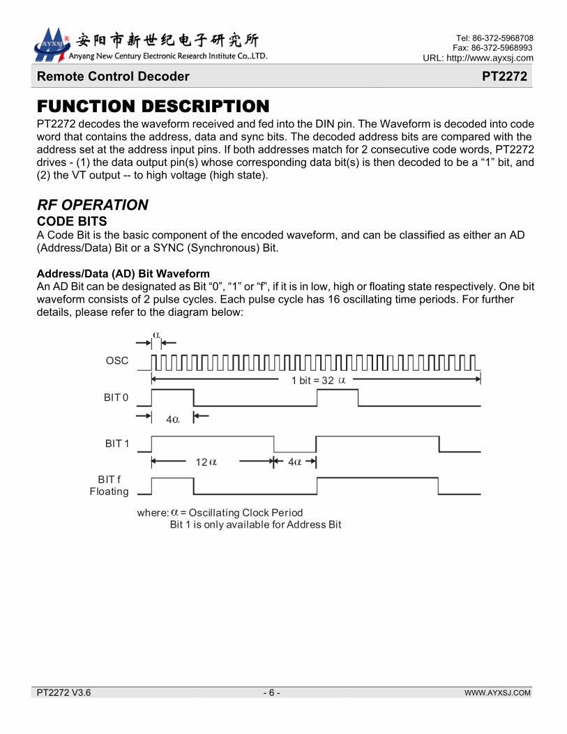
FUNCTION DESCRIPTION PT2272 decodes the waveform received and fed into the DIN pin. The Waveform is decoded into code word that contains the address, data and sync bits. The decoded address bits are compared with the address set at the address input pins. If both addresses match for 2 consecutive code words, PT2272 drives - (1) the data output pin(s) whose corresponding data bit(s) is then decoded to be a “1” bit, and (2) the VT output -- to high voltage (high state). RF OPERATION CODE BITS A Code Bit is the basic component of the encoded waveform, and can be classified as either an AD (Address/Data) Bit or a SYNC (Synchronous) Bit. Address/Data (AD) Bit Waveform An AD Bit can be designated as Bit “0”, “1” or “f”, if it is in low, high or floating state respectively. One bit waveform consists of 2 pulse cycles. Each pulse cycle has 16 oscillating time periods. For further details, please refer to the diagram below:
1 bit = 32
4
12 4
where: = Oscillating Clock Period Bit 1 is only available for Address Bit
OSC
BIT 0
BIT 1
BIT fFloating
WWW.AYXSJ.COM
Tel: 86-372-5968708 Fax: 86-372-5968993
URL: http://www.ayxsj.com
PT2272 V3.6 - 7 -
Remote Control Decoder PT2272
Synchronous (Sync.) Bit Waveform The Synchronous Bit Waveform is 4 bits long with 1/8 bit width pulse. Please refer to the diagram below:
1/8 bit width = 4
4 bit width = 128
Note: 1 bit = 32 CODE WORD A group of Code Bits is called a Code Word. A Code Word consists of 12 AD bits followed by one Sync Bit. The 12 AD bits are interpreted as either address or data bits depending on the PT2272 version used. Please refer to the diagrams below: PT2272: A0 A1 A2 A3 A4 A5 A6 A7 A8 A9 A10 A11 SYNC
SINGLE RESISTOR OSCILLATOR The built-in oscillator circuitry of PT2272 allows a precision oscillator to be constructed with only an external resistor. For the PT2272 to decode correctly the waveform that was received, the oscillator frequency of PT2272 must be 2.5~8 times that of the transmitting PT2262. It is a good practice to center the PT2272 oscillator frequency in this window to gain best window margin at both sides. The typical oscillator with various resistor values is shown below for both PT2262 and PT2272.
Encoder OSC Frequency Decoder OSC Frequency
100
10
1
KHz
3 6 9 12 15
V O L T A G E
R = 510 K
R = 1 MR = 2 M
R = 3.3 MR = 4.7 M
1000
100
10
3 6 9 12 15
V O L T A G E
R = 100 K
R = 240 K
R = 510 K
R = 1 M
R = 2 M
KHz
Suggested oscillator resistor values are shown below.
Note: * -- Operates when PT2272's VCC=5V to 15V ** -- Operates when PT2272's VCC= 4V to 15V This means that if the PT2272 supply voltage is lower than 5V, you have to use a lower oscillator resistor value for both PT2262 and PT2272.
WWW.AYXSJ.COM
Tel: 86-372-5968708 Fax: 86-372-5968993
URL: http://www.ayxsj.com
PT2272 V3.6 - 9 -
Remote Control Decoder PT2272
IR OPERATION In the IR Type of Operation, the functions are similar to the above descriptions, except that the output waveform carried by PT2262-IR has a frequency of 38KHz. Details are as follows. CODE BITS The Code Bits are further modulated with a 38KHz carrier frequency and can be “0”, “1” or “f” bit. Their waveforms are shown in the diagram below.
160
20
60
20 620
OSC
0
1
f
Sync
Note: = 2 clock lengths CODE WORD A Code Word is made up of code bits and the format is the same as that of the RF Code Frame. CODE FRAME Likewise, a Code Frame is made up of Code Words and the format is the same as that of RF Type of Operation. OSCILLATOR PT2262-IR is specially designed for infrared remote control applications and its output waveform carries 38KHz frequency. To get the 38KHz carrier frequency at the data output, the oscillator frequency must be 76KHz. A 440KΩ resistor connected between OSC1 and OSC2 pins of PT2262-IR is recommended. Moreover, for a matching decoder frequency, 1MΩ resistor connected between the OSC1 and OSC2 pins of PT2272 is also recommended.
WWW.AYXSJ.COM
Tel: 86-372-5968708 Fax: 86-372-5968993
URL: http://www.ayxsj.com
PT2272 V3.6 - 10 -
Remote Control Decoder PT2272
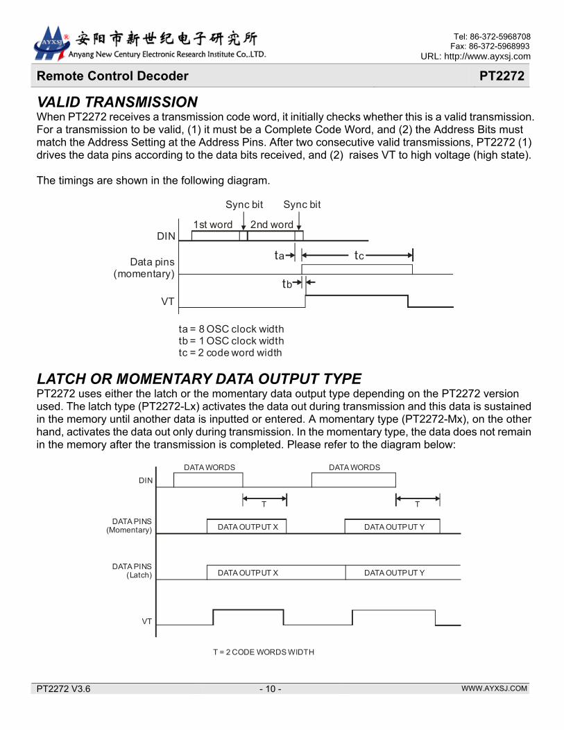
VALID TRANSMISSION When PT2272 receives a transmission code word, it initially checks whether this is a valid transmission. For a transmission to be valid, (1) it must be a Complete Code Word, and (2) the Address Bits must match the Address Setting at the Address Pins. After two consecutive valid transmissions, PT2272 (1) drives the data pins according to the data bits received, and (2) raises VT to high voltage (high state). The timings are shown in the following diagram.
Sync bit
1st word 2nd word
Sync bit
DIN
Data pins(momentary)
VT
ta tc
tb
ta = 8 OSC clock widthtb = 1 OSC clock widthtc = 2 code word width
LATCH OR MOMENTARY DATA OUTPUT TYPE PT2272 uses either the latch or the momentary data output type depending on the PT2272 version used. The latch type (PT2272-Lx) activates the data out during transmission and this data is sustained in the memory until another data is inputted or entered. A momentary type (PT2272-Mx), on the other hand, activates the data out only during transmission. In the momentary type, the data does not remain in the memory after the transmission is completed. Please refer to the diagram below:
T T
DATA WORDS DATA WORDS
DATA OUTPUT X DATA OUTPUT Y
DATA OUTPUT X DATA OUTPUT Y
DIN
DATA PINS(Momentary)
DATA PINS(Latch)
VT
T = 2 CODE WORDS WIDTH
WWW.AYXSJ.COM
Tel: 86-372-5968708 Fax: 86-372-5968993
URL: http://www.ayxsj.com
PT2272 V3.6 - 11 -
Remote Control Decoder PT2272
OPERATION FLOWCHART DECODER WITHOUT DATA OUTPUT PIN 1. When Power is turned on, PT2272 activates the Stand-By Mode. 2. It then searches for signals. If there is no signal received, it remains in the Stand-By Mode; otherwise, the address bits received are compared with the address configuration of the pins. 3. The VT goes high signifying the validation of transmission only when there are two (2) continuous frames that contain matched address bits; otherwise, VT will not be activated and the Stand-By Mode remains active. 4. Then, the Address Bits are again checked. Two continuous mismatches of the address bits would disable the VT and make the Stand-By Mode active; otherwise, the address bits are continuously checked.
Power ON
Stand-By Mode
Signal In?
Address Bits Match?
Activate VT
Address Bits Still Match?
Address Bits Still Match?
Yes
No
No
Yes
No
Yes
No
Yes
Yes No
Disable VT
Address Bits Match?
WWW.AYXSJ.COM
Tel: 86-372-5968708 Fax: 86-372-5968993
URL: http://www.ayxsj.com
PT2272 V3.6 - 12 -
Remote Control Decoder PT2272
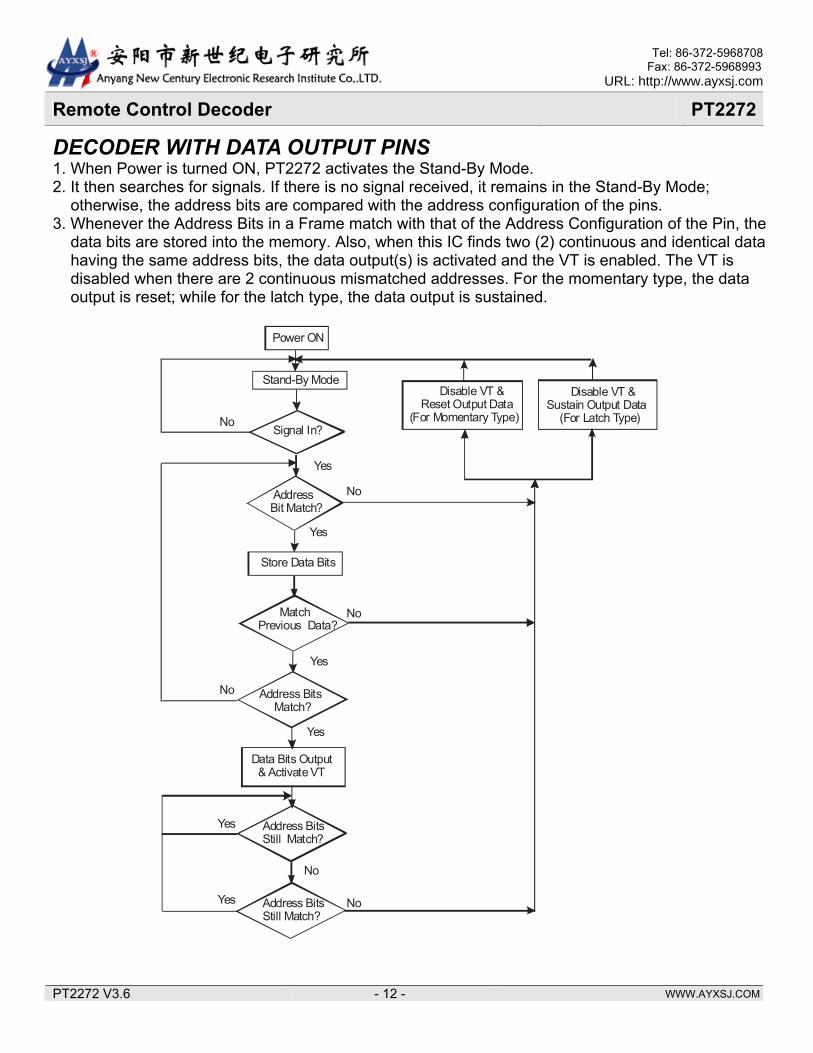
DECODER WITH DATA OUTPUT PINS 1. When Power is turned ON, PT2272 activates the Stand-By Mode. 2. It then searches for signals. If there is no signal received, it remains in the Stand-By Mode; otherwise, the address bits are compared with the address configuration of the pins. 3. Whenever the Address Bits in a Frame match with that of the Address Configuration of the Pin, the data bits are stored into the memory. Also, when this IC finds two (2) continuous and identical data having the same address bits, the data output(s) is activated and the VT is enabled. The VT is disabled when there are 2 continuous mismatched addresses. For the momentary type, the data output is reset; while for the latch type, the data output is sustained.
Power ON
Stand-By Mode
Signal In?
AddressBit Match?
Match Previous Data?
Store Data Bits
Address Bits Match?
Data Bits Output& Activate VT
Address Bits Still Match?
Address Bits Still Match?
Yes
No
No
Yes
No
No
Yes
Yes
No
Yes
Yes No
Disable VT & Reset Output Data
(For Momentary Type)
Disable VT & Sustain Output Data (For Latch Type)
WWW.AYXSJ.COM
Tel: 86-372-5968708 Fax: 86-372-5968993
URL: http://www.ayxsj.com
PT2272 V3.6 - 13 -
Remote Control Decoder PT2272
ABSLOUTE MAXIMUM RATINGS Parameter Symbol Rating Unit
Supply Voltage VCC -0.3 ~ 16.0 V Input Voltage VI -0.3 ~ VCC+0.3 V Output Voltage VO -0.3 ~ VCC+0.3 V Operating Temperature Topr -40 ~ +85 Storage Temperature Tstg -65 ~ 150
DC ELECTRICAL CHARACTERISTICS
Parameter Symbol Conditions Min. Typ. Max. UnitSupply Voltage VCC - 4 - 15 V
Stand-by Current ISB VCC = 12VDIN = 0V
OSC1 = 0V- 0.1 1 µA
VCC = 5V VOH = 3V -3 - - mA
VCC = 8V VOH = 4V -6 - - mA DOUT Output Driving Current IOH
VCC = 12V VOH = 6V -10 - - mA
VCC = 5V VOH = 3V 2 - - mA
VCC = 8V VOH = 4V 5 - - mA DOUT Output Sinking Current IOL
VCC = 12V VOH = 6V 9 - - mA
“H” Input Voltage VIH VCC 0.7VCC - VCC V “L” Input Voltage VIL VCC 0 - 0.3VCC V
WWW.AYXSJ.COM
Tel: 86-372-5968708 Fax: 86-372-5968993
URL: http://www.ayxsj.com
PT2272 V3.6 - 14 -
Remote Control Decoder PT2272
APPLICATION CIRCUIT PT2272 (NO DATA) RF APPLICATION
A0
A1
A2
A3
A4
A5
A6
A7
VCC
VT
OSC1
OSC2
DIN
A11
A10
A9
VSS A8
1
3
2
4
5
6
7
8
9
18
16
17
15
14
13
12
11
10
P 2272T
RF
5V
Rosc
PT2272 (4 DATA) RF APPLICATION CIRCUIT
A0
A1
A2
A3
A4
A5
A6
A7
VCC
VT
OSC1
OSC2
DIN
D0
D1
D2
VSS D3
1
3
2
4
5
6
7
8
9
18
16
17
15
14
13
12
11
10
PT2272-L4
RF
5V
Rosc
560
560
560
560
560
WWW.AYXSJ.COM
Tel: 86-372-5968708 Fax: 86-372-5968993
URL: http://www.ayxsj.com
PT2272 V3.6 - 15 -
Remote Control Decoder PT2272
PT2272 (4 DATA) IR APPLICATION CIRCUIT
A0
A1
A2
A3
A4
A5
A6
A7
VCC
VT
OSC1
OSC2
DIN
D0
D1
D2
VSS D3
1
3
2
4
5
6
7
8
9
18
16
17
15
14
13
12
11
10
PT2272-L4
5V
Rosc
560
560
560
560
560
Receiver
10KNPN
WWW.AYXSJ.COM
Tel: 86-372-5968708 Fax: 86-372-5968993
URL: http://www.ayxsj.com
PT2272 V3.6 - 16 -
Remote Control Decoder PT2272
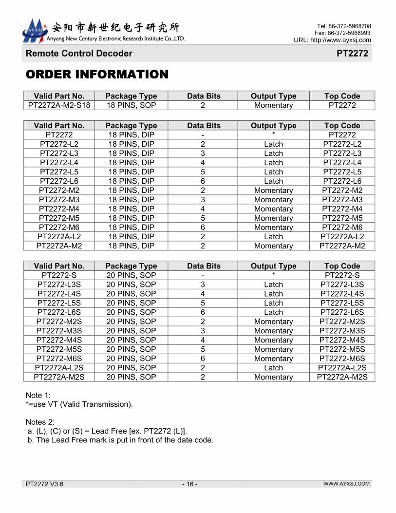
ORDER INFORMATION
Valid Part No. Package Type Data Bits Output Type Top Code PT2272A-M2-S18 18 PINS, SOP 2 Momentary PT2272
Valid Part No. Package Type Data Bits Output Type Top Code
Note 1: *=use VT (Valid Transmission). Notes 2: a. (L), (C) or (S) = Lead Free [ex. PT2272 (L)]. b. The Lead Free mark is put in front of the date code.
WWW.AYXSJ.COM
Tel: 86-372-5968708 Fax: 86-372-5968993
URL: http://www.ayxsj.com
PT2272 V3.6 - 17 -
Remote Control Decoder PT2272
PACKAGE INFORMATION 18 PINS, SOP, 300MIL
Symbol Min. Nom. Max. A 2.35 2.65
A1 0.10 0.30 B 0.33 0.51 C 0.23 0.32 D 11.35 11.75 E 7.40 7.60 e 1.27 BASIC H 10.00 10.65 h 0.25 0.75 L 0.40 1.27 ∞ 0° 8°
WWW.AYXSJ.COM
Tel: 86-372-5968708 Fax: 86-372-5968993
URL: http://www.ayxsj.com
PT2272 V3.6 - 18 -
Remote Control Decoder PT2272
Notes: 1. Dimensioning and tolerancing per ANSI Y14.5-1982. 2. Dimension “D” does not include mold flash, protrusions or gate burrs. Mold Flash. protrusion or
gate burrs shall not exceed 0.15mm (0.006 in) per side. 3. Dimension “E” does not include interlead flash or protrusions. Interlead flash or protrusions shall
not exceed 0.25mm (0.010 in) per side. 4. The chamfer on the body is optional. It is not present, a visual index feature must be located within the crosshatched area. 5. “L” is the length of the terminal for soldering to substrate. 6. “N” is the number of terminal positions. (N=18) 7. The lead width “B” as measured 0.36mm (0.014 in) or greater above the seating plane, shall not
exceed a maximum value of 0.61mm (0.24 in) 8. Controlling dimension: MILLIMETER. 9. Refer to JEDEC MS-013 Variation AB.
JEDEC is the trademark of JEDEC SOLID STATE TECHNOLOGY ASSOCIATION.
WWW.AYXSJ.COM
Tel: 86-372-5968708 Fax: 86-372-5968993
URL: http://www.ayxsj.com
PT2272 V3.6 - 19 -
Remote Control Decoder PT2272
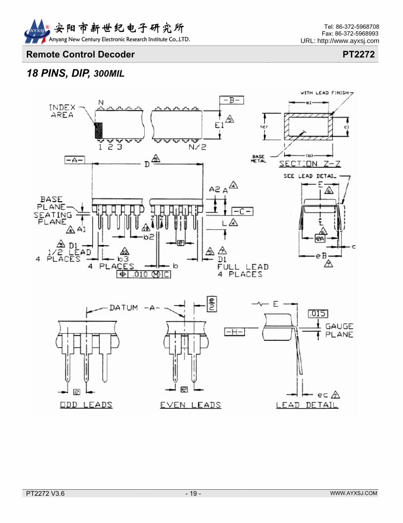
18 PINS, DIP, 300MIL
WWW.AYXSJ.COM
Tel: 86-372-5968708 Fax: 86-372-5968993
URL: http://www.ayxsj.com
PT2272 V3.6 - 20 -
Remote Control Decoder PT2272
Symbol Min. Nom. Max. A 0.21
A1 0.15 A2 0.115 0.13 0.195 b 0.014 0.018 0.022
b2 0.045 0.06 0.07 b3 0.03 0.039 0.045 c 0.008 0.01 0.014 D 0.88 0.90 0.92 D1 0.005 E 0.30 0.31 0.325
E1 0.24 0.25 0.28 e 0.1 BASIC
eA 0.3 BASIC eB 0.43 eC 0.00 0.60 L 0.115 0.13 0.15
Notes: 1. All dimensioning are in INCHES. 2. Dimensioning and tolerancing per ANSI Y14.5M-1982. 3. Dimension“A”,“A1”and “L” are measured with package seated in JEDEC Seating Plane Gauge GS-3. 4. “D”, “D1” and “E1” dimensions do not include mold flash or protrusions. Mold flash or protrusions shall not exceed 0.010 inch. 5. “E” and “eA” measured with the leads constrained to be perpendicular to datum-c- . 6. “eB” and “eC” are measured at the lead tips with the leads unconstrained. 7. “N” is the number of terminal position (N=18). 8. Pointed or rounded lead tips are preferred to ease insertion. 9. “b2” and “b3” maximum dimensions are not include dambar protrusions. Damber protrusions shall
not exceed 0.010 inch (0.25mm) 10. Distance between leads including Damber protrusions to be 0.005 inch minimum. 11. Datum plane -H- coincident with the bottom of lead, where lead exits body. 12. Refer to JEDEC MS-001, Variation AC
JEDEC is the trademark of JEDEC SOLID STATE TECHNOLOGY ASSOCIATION.
WWW.AYXSJ.COM
Tel: 86-372-5968708 Fax: 86-372-5968993
URL: http://www.ayxsj.com
PT2272 V3.6 - 21 -
Remote Control Decoder PT2272
20PINS, SOP, 300 MIL
Symbol Min. Nom. Max. A 2.35 2.65 A1 0.10 0.30 B 0.33 0.51 C 0.23 0.32 D 12.60 13.00 E 7.40 7.60 e 1.27 bsc. H 10.00 10.65 h 0.25 0.75 L 0.40 1.27 α 0° 8°
WWW.AYXSJ.COM
Tel: 86-372-5968708 Fax: 86-372-5968993
URL: http://www.ayxsj.com
PT2272 V3.6 - 22 -
Remote Control Decoder PT2272
Notes: 1. Dimensioning and tolerancing per ANSI Y14.5M-1982. 2. Dimension “D” does not include mold flash, protrusions or gate burrs. Mold Flash, protrusion or gate burrs shall not exceed 0.15 mm (0.006 in) per side. 3. Dimension “E” does not include interlead flash or protrusions. Interlead flash or protrusions shall not exceed 0.25 mm (0.010 in) per side. 4. The chamfer on the body is optional. It is not present, a visual index feature must be located within the crosshatched area. 5. “L” is the length of the terminal for soldering to a substrate. 6. N is the number of the terminal positions (N=20) 7. The lead width “B” as measured 0.36 mm (0.014 in) or greater above the seating plane, shall not exceed a maximum value of 0.61 mm (0.24 in). 8. Controlling dimension: MILLIMETER. 9. Refer to JEDEC MS-013, Variation AC. JEDEC is the trademark of JEDEC SOLID STATE TECHNOLOGY ASSOCIATION.