Design of a multi-agent, fibercomposite digital fabrication system
The MIT Faculty has made this article openly available. Please share how this access benefits you. Your story matters.
Citation Kayser, Markus et al. "Design of a multi-agent, fiber compositedigital fabrication system." Science Robotics 3, 22 (September2018): eaau5630 © 2018 The Authors
As Published http://dx.doi.org/10.1126/scirobotics.aau5630
Publisher American Association for the Advancement of Science (AAAS)
Version Original manuscript
Citable link https://hdl.handle.net/1721.1/123791
Terms of Use Creative Commons Attribution-Noncommercial-Share Alike
Detailed Terms http://creativecommons.org/licenses/by-nc-sa/4.0/
Science Robotics Manuscript Template Page 1 of
10
Design of a Multi-agent, Fiber Composite Fabrication System
Markus Kayser, Levi Cai, Sara Falcone, Christoph Bader, Nassia Inglessis, Barrak Darweesh, and Neri Oxman
Abstract Designing novel platforms that can use new materials and fabrication strategies in a fully autonomous, cooperative
fashion can help create architectures faster and more reliably in remote environments.
Fig. 1. (A) Each Fiberbot consists of a wind arm, a reversibly inflatable mandrel, and subsystems for navigation and
control. (B) By winding fiber and photocurable resin around themselves, robots create fiber-reinforced composite
tubes that they can climb and extend. (C) A possible application of the system to create a useful structure is proposed
using a design flocking framework, although the spacing between tubes is narrower than can be fabricated by our
current system. (D) An architectural scale print was built by 16 identical Fiberbots operating in parallel over two
days.
Some of nature’s most successful organisms are builders. Spiders can vary chemical compositions of their silk to
create complex webs that are lightweight yet highly durable to trap prey. Ants, bees, and termites rely on simple
communication strategies to coordinate and parallelize construction tasks. These species crawl on their own structures
to expand their work volume. Humans are similarly interested in more efficient construction materials and strategies
to automate, parallelize, and scale construction. Inspired by nature, we aimed to combine fibrous composite materials
Science Robotics Manuscript Template Page 2 of 10
with a multi-robot fabrication system to efficiently create on-site architectural structures that withstand variable
environments.
Previous studies identified autonomous mobility and simple communication as key components of scalable,
cooperative multi-robot construction, but mainly focused on assembly of pre-fabricated parts [1], [2]. Nature
ubiquitously relies on fibers and hierarchical fiber arrangements, such as those found in trees or bones, for strength
and flexibility [3], [4]. Recent work [5], [6] suggested synthetic fiber-reinforced composites (FRC), such as fiberglass
or carbon fiber, can mimic aspects of natural materials to achieve more complex and higher-performing properties in
architecture. However, the molds –or mandrels–required to create these architectures are geometrically constrained
and expensive to make and maintain. A process that allows fabrication of more complex geometries without
sophisticated infrastructure is important to automating FRC construction at scale and on-site.
To explore these possibilities, we present a novel autonomous fabrication system that combines FRC and
hierarchical design methodologies with a parallelized fabrication strategy. A team of Fiberbots, each an identical
robot consisting of a fiber winding system that uses fiberglass thread and UV-curing resin, builds self-supporting
composite tubes. Each robot is mobile, allowing it to create a single tube of pre-specified curvature, up to tens of
times longer than itself. Individual tubes are interwoven and constructed simultaneously by multiple robots working
in parallel, to create larger architectural structures.
Creating fiberglass tubes with controlled curvature and arbitrary length
Initially, an autonomous system is needed that can create large, specified fiberglass structures. Each robot constructs
an independent tube sequentially, one segment at a time from a single strand of fiberglass thread and photocurable
resin. Each segment, up to 90 mm in length and roughly 100 mm in diameter, is appended with overlap to the end of
an existing tube, and then cured and bonded to the growing structure. Controlled curvature is achieved in the tube by
tilting each segment relative to a previous segment.
Each robot embodies a mandrel with an inflatable silicone membrane that fixes the robot to the existing
structure and provides a cylindrical mold. A wind arm pulls fiber and resin from a ground-based storage system,
mixes the materials in the nozzle and deposits the composite mixture onto the surface of the mandrel. The wind arm
also controls segmental fiber patterning and thickness. Through mandrel inflation or deflation, various diameter tubes
are created. By sufficiently shrinking its radius, through deflation, the mandrel can detach from the cured structure,
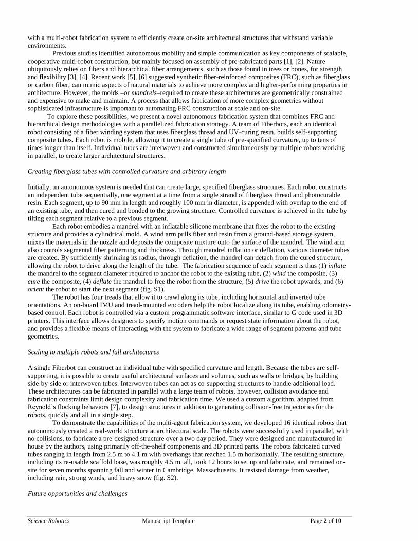
allowing the robot to drive along the length of the tube. The fabrication sequence of each segment is thus (1) inflate
the mandrel to the segment diameter required to anchor the robot to the existing tube, (2) wind the composite, (3)
cure the composite, (4) deflate the mandrel to free the robot from the structure, (5) drive the robot upwards, and (6)
orient the robot to start the next segment (fig. S1).
The robot has four treads that allow it to crawl along its tube, including horizontal and inverted tube
orientations. An on-board IMU and tread-mounted encoders help the robot localize along its tube, enabling odometry-
based control. Each robot is controlled via a custom programmatic software interface, similar to G code used in 3D
printers. This interface allows designers to specify motion commands or request state information about the robot,
and provides a flexible means of interacting with the system to fabricate a wide range of segment patterns and tube
geometries.
Scaling to multiple robots and full architectures
A single Fiberbot can construct an individual tube with specified curvature and length. Because the tubes are self-
supporting, it is possible to create useful architectural surfaces and volumes, such as walls or bridges, by building
side-by-side or interwoven tubes. Interwoven tubes can act as co-supporting structures to handle additional load.
These architectures can be fabricated in parallel with a large team of robots, however, collision avoidance and
fabrication constraints limit design complexity and fabrication time. We used a custom algorithm, adapted from
Reynold’s flocking behaviors [7], to design structures in addition to generating collision-free trajectories for the
robots, quickly and all in a single step.
To demonstrate the capabilities of the multi-agent fabrication system, we developed 16 identical robots that
autonomously created a real-world structure at architectural scale. The robots were successfully used in parallel, with
no collisions, to fabricate a pre-designed structure over a two day period. They were designed and manufactured in-
house by the authors, using primarily off-the-shelf components and 3D printed parts. The robots fabricated curved
tubes ranging in length from 2.5 m to 4.1 m with overhangs that reached 1.5 m horizontally. The resulting structure,
including its re-usable scaffold base, was roughly 4.5 m tall, took 12 hours to set up and fabricate, and remained on-
site for seven months spanning fall and winter in Cambridge, Massachusetts. It resisted damage from weather,
including rain, strong winds, and heavy snow (fig. S2).
Future opportunities and challenges
Science Robotics Manuscript Template Page 3 of 10
The Fiberbots system demonstrates the feasibility of autonomous, cooperative, continuous construction, and
exploring new building materials, such as FRCs. Though additional implementation of sensors for localization,
manipulation and controls is needed to fully realize the system, we have demonstrated a novel fabrication method,
introducing new ways to both digitally design and fabricate on-site. This approach to simultaneously designing end-
to-end fabrication platforms, material systems, and algorithms can increase manufacturing capacity, enable
previously in-fabricable forms, and may even allow for use in harsh environments or extra-terrestrial domains.
References and Notes
[1] K. Petersen, R. Nagpal, and J. Werfel, “TERMES: An Autonomous Robotic System for Three-Dimensional
Collective Construction,” in Robotics: Science and Systems (RSS), 2011.
[2] F. Augugliaro et al., “The Flight Assembled Architecture installation: Cooperative construction with flying
machines,” IEEE Control Syst., vol. 34, no. 4, pp. 46–64, Aug. 2014.
[3] P. Fratzl and R. Weinkamer, “Nature’s hierarchical materials,” Prog. Mater. Sci., vol. 52, no. 8, pp. 1263–1334,
Nov. 2007.
[4] S. Lapidot, S. Meirovitch, S. Sharon, A. Heyman, D. L. Kaplan, and O. Shoseyov, “Clues for biomimetics from
natural composite materials,” Nanomed., vol. 7, no. 9, pp. 1409–1423, Sep. 2012.
[5] M. Doerstelmann et al., “ICD/ITKE Research Pavilion 2014–15: Fibre Placement on a Pneumatic Body Based
on a Water Spider Web,” Archit. Des., vol. 85, no. 5, pp. 60–65, Sep. 2015.
[6] “ICD/ITKE Research Pavilion 2016-17 | achimmenges.net.” .
[7] C. W. Reynolds, “Flocks, Herds, and Schools: A Distributed Behavioral Model,” SIGGRAPH, Jul. 1987.
Acknowledgements: The authors would like to acknowledge Robert R. Garriga, Melinda Szabo, Jami Rose who
helped fabricate, design and build parts of this system. Thank you to Silas Hughes who performed the
photogrammetry of the structure and Dr. James Weaver for additional CT imaging and analysis.
Funding: GettyLab
Science Robotics Manuscript Template Page 4 of 10
Supplementary Materials
Movie S1. Fabrication sequence
Movie S2. Fiberbot operation
Movie S3. Multirobot fabrication demo
Movie S4. Fiberbot case study
Fig. S1. System overview
Fig. S2. The final structure
Fig. S3. Timelapse
Fig. S4. Render and fabrication comparison
Fig. S5. Changing curling bias
Fig. S6. Relation between robot geometry and overall fabrication constraints
Fig. S7. Various fiber patterns
Fig. S8. Concept rendering
Fig. S9. Collision avoidance concept rendering Fig. S10. Photo of a single Fiberbot.
Fig. S1. System overview. (1)-(4) shows the sequence for the construction of a single segment of the composite tube
with a single robot. (1) is the initial setup of the system, consisting of a spool of fiberglass thread, steel base, resin
reservoir, and a single robot. The robot is tethered to the base via the black cable, which provides resin, electrical
power, and communication with the resin pump. (2) shows an inflated robot, with UV LEDs turned on, as it winds a
single segment. (3) shows a deflated (and hence delaminated) robot, after completing a third segment, it has driven up
and tilted itself to curve the next segment of the composite tube. (4) Shows the robot inflated once more, with an
overlap over the previous segment, and is ready to wind another segment.
Science Robotics Manuscript Template Page 5 of 10
Fig. S2. The final structure remains undamaged after several months in various weather conditions.
Fig. S3. Timelapse of the architectural-scale print over the course of two days.
Science Robotics Manuscript Template Page 6 of 10
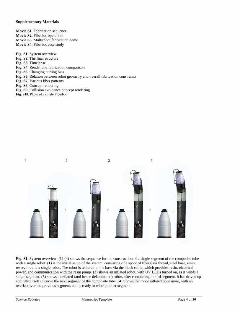
Fig. S4. (A)-(D) are all shown from the same perspective. (A) shows the actual completed structure, (B) is the initial
design of the structure, (C) is a photogrammetry scan of the structure using Pix4D, and (D) is (B) and (C) overlaid on
each other to illustrate the error and drift that occurs due to inaccuracies in the localization process.
Fig. S5. From left to right, shows how changing curling bias affects the overall structure
Science Robotics Manuscript Template Page 7 of 10
Fig. S6. Relation between robot geometry and overall fabrication constraints are shown here. In (A), the protruding
sections of the robot, in addition to the winding motions of the arm, create a collision cylinder CC, with radial CCR
and linear CCL components. This affects the minimum distance d that tubes can be fabricated together as shown in
(B). Three points on the robot body can self-collide with its own tube, which limits the maximum angle ϴ that the
robot can tilt, shown in (C). In turn, this limits the minimum curve radius R of its own tube, highlighted in (D).
Science Robotics Manuscript Template Page 8 of 10
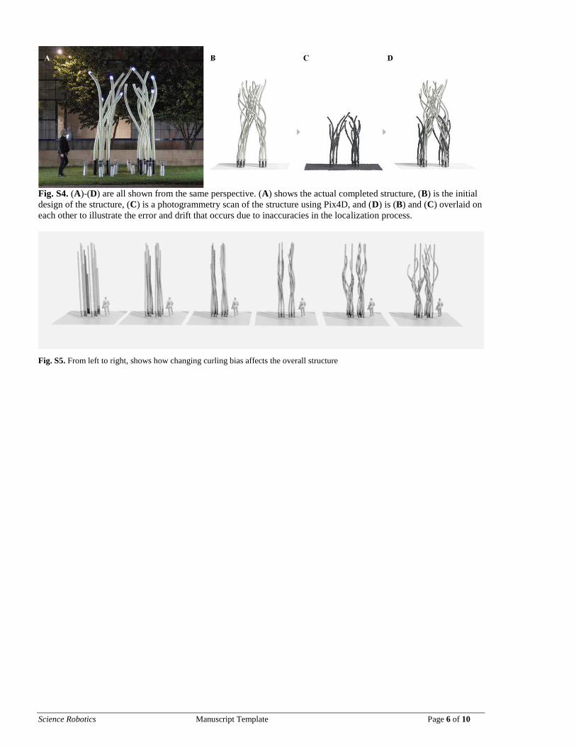
Fig. S7. Various fiber patterns wound using a single Fiberbot, achieved by varying speed ratios between the linear
and rotary motions of the wind arm.
Fig. S8. Concept rendering of the case study before construction.
Science Robotics Manuscript Template Page 9 of 10
Fig. S9. Concept rendering where Fiberbots can detect and avoid arbitrary obstacles, the flocking based design
method can still work at build-time.
Science Robotics Manuscript Template Page 10 of 10
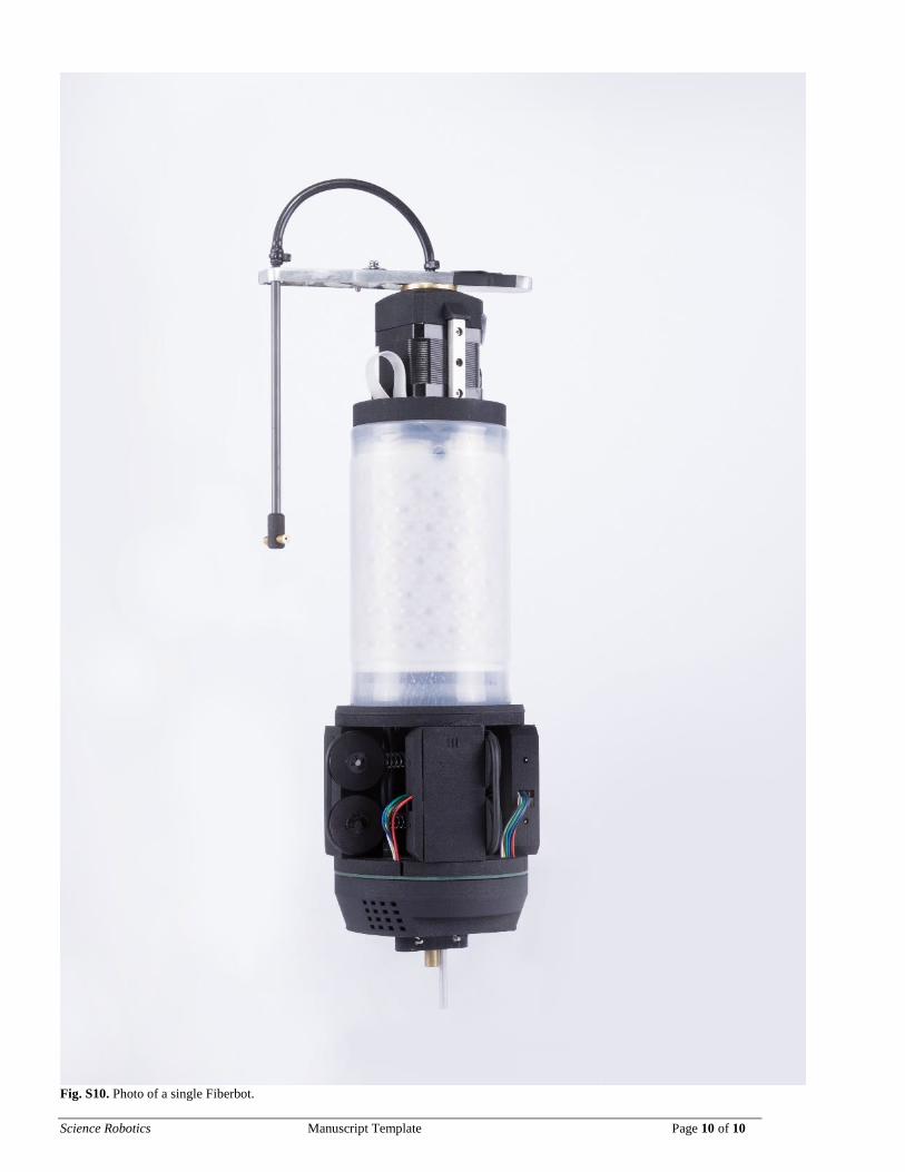
Fig. S10. Photo of a single Fiberbot.


![Chapter 1and Wakerly [Wakerly, 2006], respectively. Digital Signal Processing refers to the processing of signals using dig-ital electronics, for example to extract, suppress, or highlight](https://static.documents.pub/doc/80x56/5e80603c6d38a3479c596f86/chapter-1-and-wakerly-wakerly-2006-respectively-digital-signal-processing-refers.jpg)
