Page 1
DESIGN A FALLING FILM HEAT EXCHANGER
By
YASSER BAHAMDAN Comp. No. 0908715
MOHAMMED ALSHIEKH Comp. No. 0908762
MOHAMMED JAMBI Comp. No. 0909116
ABDULLAH ALSHARIEKH Comp. No. 0910777
AMJAD MELEBARI Comp. No. 0908724
Supervised by
Dr. HANI SAITand Prof. YACINE KHETIB
Advisory committee
Prof. YACINE KHETIB THERMAL ENG, FoE-KAU
Dr. NEDIM TURKMEN THERMAL ENG, FoE-KAU
Customer
DR.HANI SAIT THERMAL ENG, FoE-KAU
MECHANICAL ENGINEERING DEPARTMENT
THERMAL ENGINEERING AND DESALINATION TECNOLOGY PROGRAM
FACULTY OF ENGINEERING
KING ABDULAZIZ UNIVERSITY
JEDDAH - SAUDI ARABIA
SUMMER 1434-35 H – 2013-14 G
Page 2
DESIGN A FALLING FILM HEAT EXCHANGER
By
YASSER BAHAMDAN Comp. No. 0908715
MOHAMMED ALSHIEKH Comp. No. 0908762
MOHAMMED JAMBI Comp. No. 0909116
ABDULLAH ALSHARIEKH Comp. No. 0910777
AMJAD MELEBARI Comp. No. 0908724
A senior project report submitted in partial fulfillment
Of the requirements for the degree of
BACHELOR OF SCIENCE
In
MECHANICAL ENGINEERING (Thermal Engineering and Desalination
Technology) PROGRAM
Supervised by:
Dr. HANI SAIT ………………………………….
Prof. YACINE KHETIB ………………………………….
Approved by:
Dr. NEDIM TURKMEN ………………………………….
MECHANICAL ENGINEERING DEPARTMENT
THERMAL ENGINEERING AND DESALINATION TECNOLOGY PROGRAM
FACULTY OF ENGINEERING
KING ABDULAZIZ UNIVERSITY
JEDDAH - SAUDI ARABIA
SUMMER 1434-35 H – 2013-14 G
Page 3
iii
الــحــوـــد هلل رب
الــعـــالــوـيـــن
Page 4
iv
و الصالة و السالم على أشزف
األنبياء و الوزســلين سيدنا هحود و
على آله و صحبه أجوعين
قال هللا تعالى في كتابه الكزين
الهذين آهنوا هنكن والهذين أوتوا العلن } يزفع هللاه
[ 11 : الوجا لت ] { رجاثت
Page 5
v
Acknowledgement
Thanks to Allah, the most Gracious and most Merciful. Firstly, we pray to Allah for His
guidance and protection throughout our life. We glorify His name through this small
accomplishment. We ask Him, with hope only in Him, to accept our efforts. Secondly,
peace and blessing be upon His Prophet Mohammed. Thirdly, we thank our parents for
their patience and endless support. Thanks to Dr. Hani Sait and Dr. YacineKhetib our
advisors for guiding this work with his knowledge and experience, also we thank
Dr.Nadeem Turkmen to advise and support us in writing processes of this report.
Finally, we thank all whom who helped us, directly and indirectly, to accomplish this
work especially Mechanical Engineering Department, Chairman and faculty members.
Page 6
vi
EXECUTIVE SUMMARY
A small scale falling film heat exchanger is designed to beused in domestic and
industrial applications as a main objective of this project. Another objective is to
optimize the tube spacing and liquid flow rate influence on falling film formation with
heated water should not exceed 43oC, a maximum flow rate from a cooling path is 4
kg/min, and a minimum flow rate from the falling film at 1 kg/ min. This objective is to
increasethe heat transfer coefficient. A test box was built consisting of test section and
the test section consisted of feed tubes, test tubes and tank.All the tubes are made of
copper, which has a high thermal conductivity. The feed tube is setup above the test
section, its height is 300 mm the length is 400 mm and the width is 100mm, a line of
holes were drilled 2 mm apart from each other, providing26 holes.The feed tube has
inside and outside diameters of 12.7 mm and 10 mm. It receives liquid from a cooling
path. Three test tubes configured above each other with diameter of 12.7 mm are placed
at a pitch of 130 mm under the feed tubes. They were all held by the supporting box,
which was made of transparentplastic glasses. The cooling path gave the capability of
adjusting the temperature and to keep it constant.It was used to supply hot water inside
the test tubes. A constant temperature tap water provides pure water to the outside of the
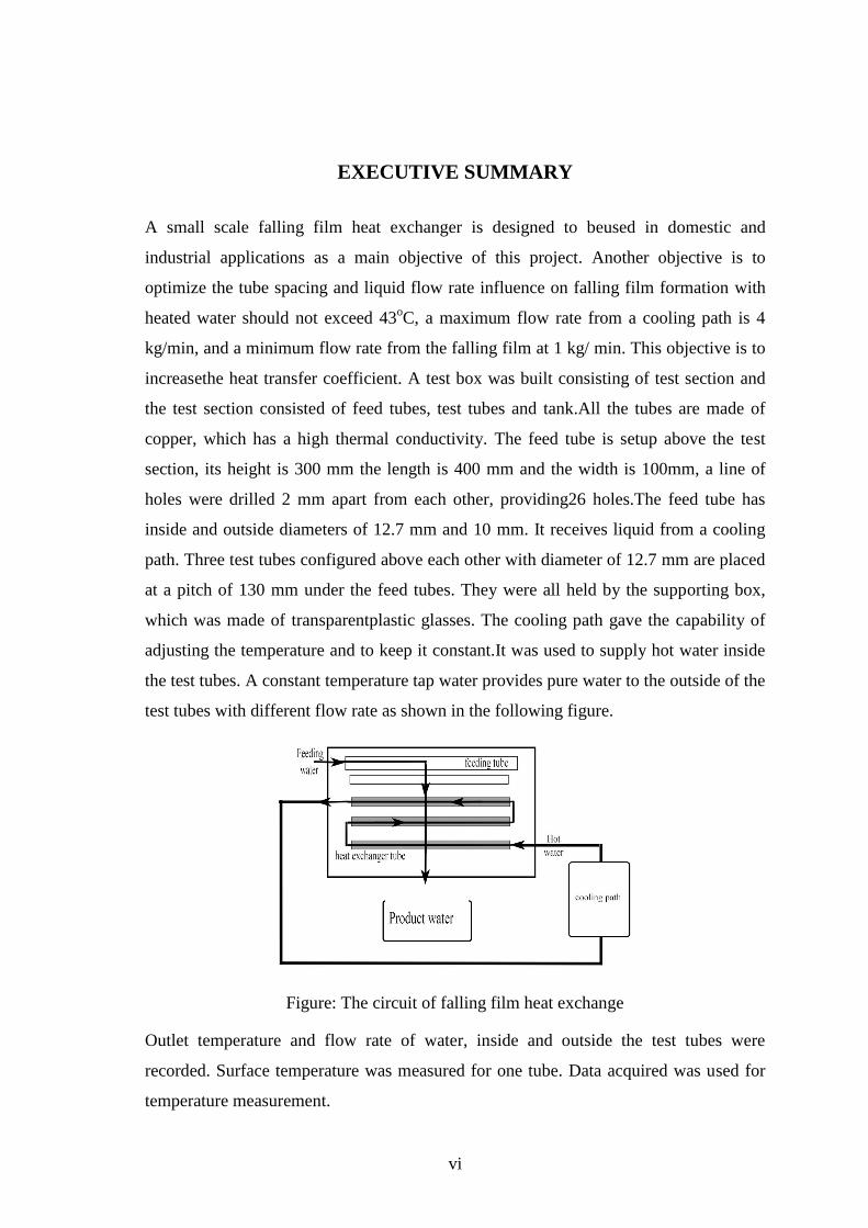
test tubes with different flow rate as shown in the following figure.
Figure: The circuit of falling film heat exchange
Outlet temperature and flow rate of water, inside and outside the test tubes were
recorded. Surface temperature was measured for one tube. Data acquired was used for
temperature measurement.
Page 7
vii
For good results we chose a copper tube for the internal horizontal tubes, which we
named it "test tube",for more accurate readings, the test tubes were setup to be movable,
transparent neon fiberglass as the box material and double groove for the internal tubes
surface. After studying the falling form, we decide to set the falling as a sheet jet.
This type of heat exchanger is Innocuous to the environment, with no side effects
because it consists of few and simple parts. Falling film heat exchanger helps to save
more power than the other types of heat exchanger and the reason for that are low
pumping power required, also because this technique mostly depends on the gravity, the
device has a high heat transfer coefficient and easy to maintenance with this advantages
the device also reduce power consumption and cost value.
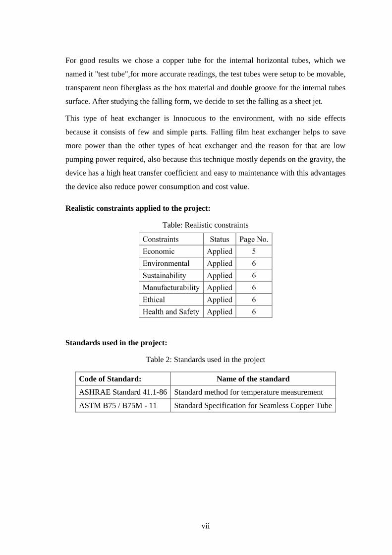
Realistic constraints applied to the project:
Table: Realistic constraints
Constraints Status Page No.
Economic Applied 5
Environmental Applied 6
Sustainability Applied 6
Manufacturability Applied 6
Ethical Applied 6
Health and Safety Applied 6
Standards used in the project:
Table 2: Standards used in the project
Code of Standard: Name of the standard
ASHRAE Standard 41.1-86 Standard method for temperature measurement
ASTM B75 / B75M - 11 Standard Specification for Seamless Copper Tube
Page 8
viii
TABLE OF CONTENTS
Acknowledgement ............................................................................................................ v
EXECUTIVE SUMMARY ............................................................................................. vi
LIST OF FIGURES ......................................................................................................... xi
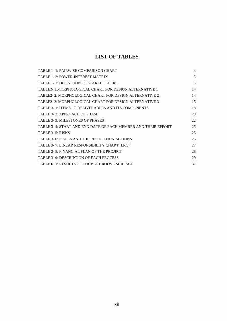
LIST OF TABLES .......................................................................................................... xii
Nomenclature ................................................................................................................. xiii
CHAPTER 1: PROBLEM DEFINITION ...................................................................... 1
1.1 Project idea or problem ....................................................................................................... 1
1.2 Situation Description ........................................................................................................... 1
1.3 Revise Client Problem Statement ........................................................................................ 2
1.4 Need and opportunity .......................................................................................................... 2
1.5 Project Scoping ................................................................................................................... 2
1.6 Project objectives ................................................................................................................ 3
1.7 Design attributes of the objectives ...................................................................................... 3
1.8 Objectives tree with metrics ................................................................................................ 3
1.9 Prioritized list of design attributes....................................................................................... 4
1.10 Project customers and stakeholders ..................................................................................... 4
1.11 Realistic constraints ............................................................................................................. 5
1.12 Project other constraints ...................................................................................................... 6
1.13 Literature review ................................................................................................................. 6
CHAPTER 2: CONCEPTUAL DESIGN ...................................................................... 9
2.1 Quality Function Deployment (QFD) ................................................................................. 9
2.2 Major Function .................................................................................................................. 10
2.3 Design Function ................................................................................................................ 10
2.4 Transparent Box ................................................................................................................ 10
2.5 Black Box .......................................................................................................................... 11
2.6 Function-Mean Tree .......................................................................................................... 12
2.7 Morphological Chart ......................................................................................................... 14
2.8 Pugh‟s Method .................................................................................................................. 16
CHAPTER 3: PROJECT MANAGEMENT ................................................................ 17
3.1 Structure ............................................................................................................................ 17
Page 9
ix
3.2 Project Deliverables .......................................................................................................... 17
3.3 Work Breakdown Structure (WBS) .................................................................................. 18
3.4 Project Plan ....................................................................................................................... 20
3.5 Project Considerations ....................................................................................................... 25
3.6 Responsibilities ................................................................................................................. 27
3.7 Financial Plan .................................................................................................................... 28
3.8 Quality Plan ....................................................................................................................... 29
CHAPTER 4: DESIGN METHODOLOGY................................................................ 30
4.1 Introduction ....................................................................................................................... 30
4.2 Scope and Limitations of the work .................................................................................... 30
4.3 Measuring Techniques ...................................................................................................... 30
4.4 Governing equations ......................................................................................................... 31
CHAPTER 5: THERMAL SIZING OF FALLING FILM HEAT EXCHANGER ..... 34
5.1 Introduction ....................................................................................................................... 34
5.2 Main technical and operation data ..................................................................................... 35
5.3 Heat transfer rate for falling film ...................................................................................... 35
5.4 Heat transfer rate for cooling path ..................................................................................... 35
5.5 Heat transfer rate ratio ....................................................................................................... 35
5.6 Overall heat transfer of falling film ................................................................................... 36
5.7 Nusselt number of falling film .......................................................................................... 36
5.8 Reynolds number of falling film ....................................................................................... 36
CHAPTER 6: DESIGN OPTIMAZITION .................................................................. 37
CHAPTER 7: EXPERAMNITAL SETUP .................................................................. 40
7.1 Introduction ....................................................................................................................... 40
7.2 Experimental methodology ............................................................................................... 40
7.3 Design setup ...................................................................................................................... 40
7.4 Design dimensions ............................................................................................................ 43
7.5 Measurement ..................................................................................................................... 43
CHAPTER 8: PROJECT EVALUATION .................................................................. 44
8.1 Global impact analysis ...................................................................................................... 44
8.2 Economic impact ............................................................................................................... 44
8.3 Environmental impact ....................................................................................................... 44
8.4 Social impact ..................................................................................................................... 44
CHAPTER 9: CONCOLUSION .................................................................................. 45
Page 10
x
REFERENCES ............................................................................................................... 47
Page 11
xi
LIST OF FIGURES
FIGURE 1- 1: FOULING IN A HEAT EXCHANGER 1
FIGURE 1- 2: FALLING FILM IN A HEAT EXCHANGER 2
FIGURE 1- 3: SHELL AND TUBE HEAT EXCHANGER 7
FIGURE 1- 4: PLATE HEAT EXCHANGER 8
FIGURE 1- 5: FALLINF FILM MODES 8
FIGURE 2- 1: HOUSE OF QUALITY 9
FIGURE 2- 2: TRANSPARENT BOX FOR FALLING FILM HEAT EXCHANGER 11
FIGURE 2- 3: BLACK BOX FOR FALLING FILM HEAT EXCHANGER 11
FIGURE 2- 4: FUNCTION-MEAN TRE 13
FIGURE 2- 5: PUGH‟S METHOD 16
FIGURE 3- 1: ROLES OF MEMBERS 17
FIGURE 3- 3: OVERALL PLANNING BY GANTT CHART 21
FIGURE 4- 1 THERMAL RESISTANCE FOR THE CYLINDER. 31
FIGURE 5- 1: THE CIRCUIT OF FALLING FILM HEAT EXCHANGE 34
FIGURE 6- 1: RELATION BETWEEN TFF.OUT AND M 38
FIGURE 6- 2:RELATION BETWEEN Q AND M 38
FIGURE 6- 3: RELATION BETWEEN NUE AND RE 39
FIGURE 6- 4: RELATION BETWEEN U AND R 39
FIGURE 7- 1: PART OF THE DESIGN 41
FIGURE 7- 2:DDOUBLE GROOVE TUBE 42
FIGURE 7- 3:PROTOTYPE OF HEAT EXCHANGE 43
Page 12
xii
LIST OF TABLES
TABLE 1- 1: PAIRWISE COMPARISON CHART 4
TABLE 1- 2: POWER-INTEREST MATRIX 5
TABLE 1- 3: DEFINITION OF STAKEHOLDERS. 5
TABLE2- 1:MORPHOLOGICAL CHART FOR DESIGN ALTERNATIVE 1 14
TABLE2- 2: MORPHOLOGICAL CHART FOR DESIGN ALTERNATIVE 2 14
TABLE2- 3: MORPHOLOGICAL CHART FOR DESIGN ALTERNATIVE 3 15
TABLE 3- 1: ITEMS OF DELIVERABLES AND ITS COMPONENTS 18
TABLE 3- 2: APPROACH OF PHASE 20
TABLE 3- 3: MILESTONES OF PHASES 22
TABLE 3- 4: START AND END DATE OF EACH MEMBER AND THEIR EFFORT 25
TABLE 3- 5: RISKS 25
TABLE 3- 6: ISSUES AND THE RESOLUTION ACTIONS 26
TABLE 3- 7: LINEAR RESPONSIBILITY CHART (LRC) 27
TABLE 3- 8: FINANCIAL PLAN OF THE PROJECT 28
TABLE 3- 9: DESCRIPTION OF EACH PROCESS 29
TABLE 6- 1: RESULTS OF DOUBLE GROOVE SURFACE 37
Page 13
xiii
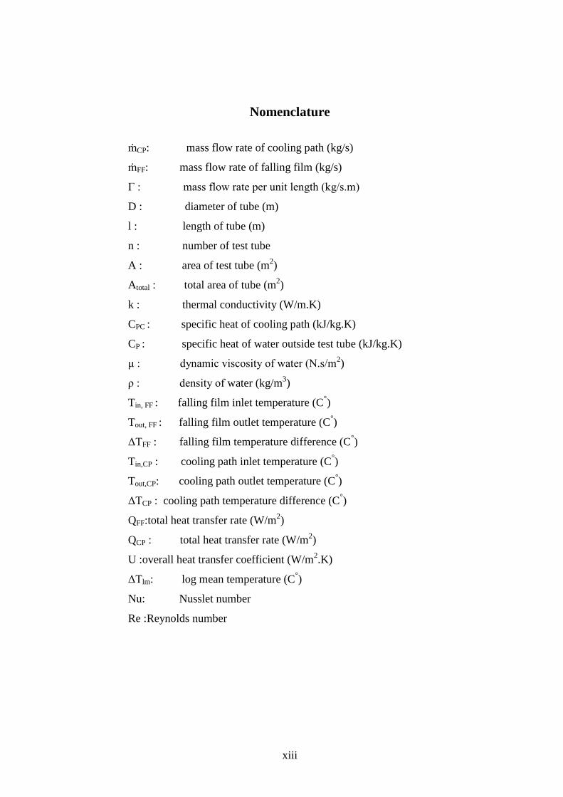
Nomenclature
ṁCP: mass flow rate of cooling path (kg/s)
ṁFF: mass flow rate of falling film (kg/s)
Γ : mass flow rate per unit length (kg/s.m)
D : diameter of tube (m)
l : length of tube (m)
n : number of test tube
A : area of test tube (m2)
Atotal : total area of tube (m2)
k : thermal conductivity (W/m.K)
CPC : specific heat of cooling path (kJ/kg.K)
CP : specific heat of water outside test tube (kJ/kg.K)
μ : dynamic viscosity of water (N.s/m2)
ρ : density of water (kg/m3)
Tin, FF : falling film inlet temperature (C°)
Tout, FF : falling film outlet temperature (C°)
ΔTFF : falling film temperature difference (C°)
Tin,CP : cooling path inlet temperature (C°)
Tout,CP: cooling path outlet temperature (C°)
ΔTCP : cooling path temperature difference (C°)
QFF:total heat transfer rate (W/m2)
QCP : total heat transfer rate (W/m2)
U :overall heat transfer coefficient (W/m2.K)
ΔTlm: log mean temperature (C°)
Nu: Nusslet number
Re :Reynolds number
Page 14
1
CHAPTER 1: PROBLEM DEFINITION
1.1 Project idea or problem
Maintenance is a major problem for most of heat exchangers. Heat exchanger that
requires the least maintenance is preferred in many applications. The idea of project is
to design a special type of heat exchanger, which requires less maintenance.
1.2 Situation Description
Heat exchanger problems are not always accompanied by obvious symptoms such as
leaks or channel intermixing. Some problems are minor but progressive, causing
higher energy consumption and performance variability. Dirt, deposits, scale and
other fouling rob your plate-type heat exchangers of their design efficiency, risking
damage to expensive equipment and unscheduled downtime for repairs. Heat
exchanger maintenance is critical for controllability and energy efficiency. Typical
problems include interior comfort complaints, off-grade product, escalating utility
bills and related troubles. Methodical diagnostics will save time and prevent wasted
effort. These should be outlined in your heat exchanger operations and maintenance
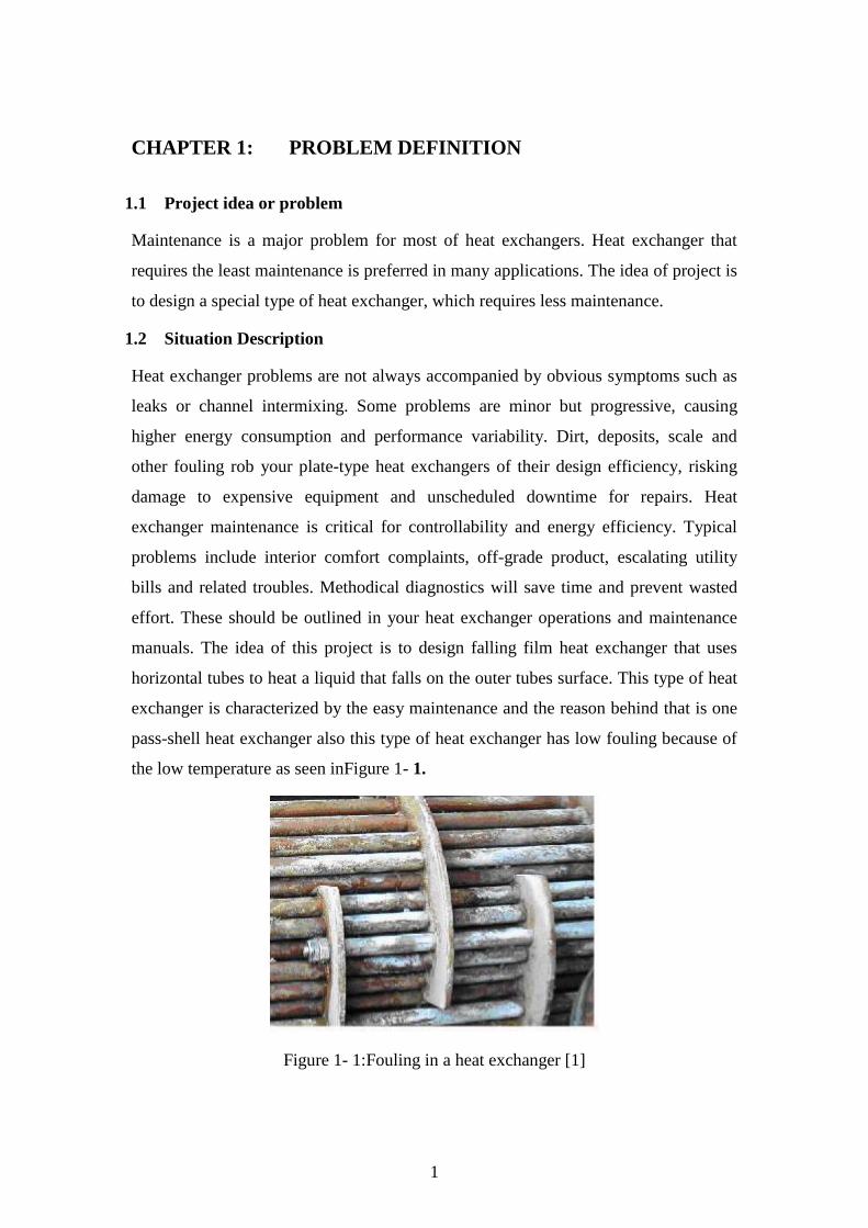
manuals. The idea of this project is to design falling film heat exchanger that uses
horizontal tubes to heat a liquid that falls on the outer tubes surface. This type of heat
exchanger is characterized by the easy maintenance and the reason behind that is one
pass-shell heat exchanger also this type of heat exchanger has low fouling because of
the low temperature as seen inFigure 1- 1.
Figure 1- 1:Fouling in a heat exchanger [1]
Page 15
2
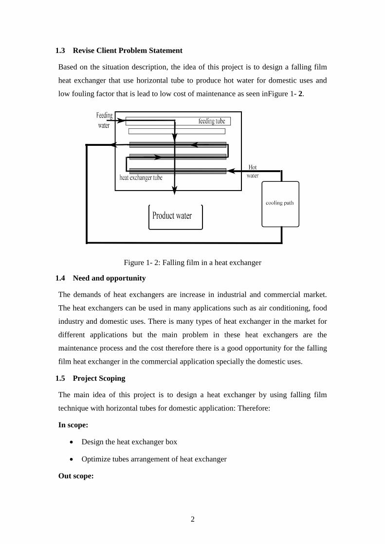
1.3 Revise Client Problem Statement
Based on the situation description, the idea of this project is to design a falling film
heat exchanger that use horizontal tube to produce hot water for domestic uses and
low fouling factor that is lead to low cost of maintenance as seen inFigure 1- 2.
Figure 1- 2: Falling film in a heat exchanger
1.4 Need and opportunity
The demands of heat exchangers are increase in industrial and commercial market.
The heat exchangers can be used in many applications such as air conditioning, food
industry and domestic uses. There is many types of heat exchanger in the market for
different applications but the main problem in these heat exchangers are the
maintenance process and the cost therefore there is a good opportunity for the falling
film heat exchanger in the commercial application specially the domestic uses.
1.5 Project Scoping
The main idea of this project is to design a heat exchanger by using falling film
technique with horizontal tubes for domestic application: Therefore:
In scope:
Design the heat exchanger box
Optimize tubes arrangement of heat exchanger
Out scope:
Page 16
3
Cold water supply,
Hot water supply.
1.6 Project objectives
The main objective of project is to design a small scale falling film heat exchanger to
heat a fluidused in domestic and industrial applications. Another objective is to
optimize the tube spacing and liquid flow rate influence on falling film formation.
This objective is to increasethe heat transfer coefficient.
1.7 Design attributes of the objectives
The meaning of the word “design attributes” is the criteria or characteristics that the
design should have. The designer should commit himself to good attributes. So if the
attributes were good enough automatically the product will be more marketable,
because the attributes are the base that the product will built on these are:
1) The artifact should be easy to maintenance.
2) The artifact shouldhave low maintenance cost
3) The artifactshould be marketable.
4) The artifactshould be reliable.
5) The design should be safe to use.
6) The design should be easy to use.
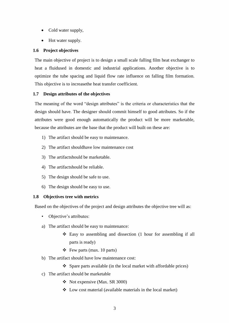
1.8 Objectives tree with metrics
Based on the objectives of the project and design attributes the objective tree will as:
• Objective‟s attributes:
a) The artifact should be easy to maintenance:
Easy to assembling and dissection (1 hour for assembling if all
parts is ready)
Few parts (max. 10 parts)
b) The artifact should have low maintenance cost:
Spare parts available (in the local market with affordable prices)
c) The artifact should be marketable
Not expensive (Max. SR 3000)
Low cost material (available materials in the local market)
Page 17
4
d) The artifactshould be reliable and safe
Safety standard and regulations applied (Occupational Safety and
Health Standards (OSHA))
Related ASTM Standard will be applied
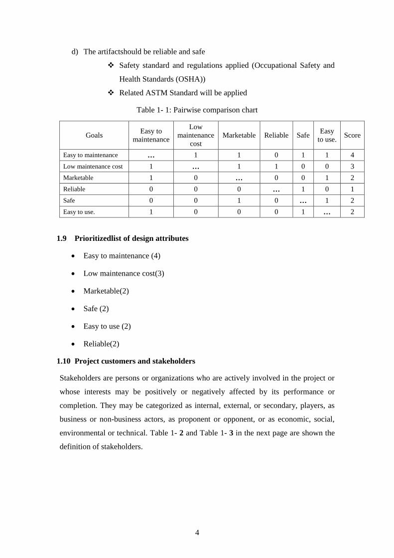
Table 1- 1: Pairwise comparison chart
Goals Easy to
maintenance
Low
maintenance
cost
Marketable Reliable Safe Easy
to use. Score
Easy to maintenance … 1 1 0 1 1 4
Low maintenance cost 1 … 1 1 0 0 3
Marketable 1 0 … 0 0 1 2
Reliable 0 0 0 … 1 0 1
Safe 0 0 1 0 … 1 2
Easy to use. 1 0 0 0 1 … 2
1.9 Prioritizedlist of design attributes
Easy to maintenance (4)
Low maintenance cost(3)
Marketable(2)
Safe (2)
Easy to use (2)
Reliable(2)
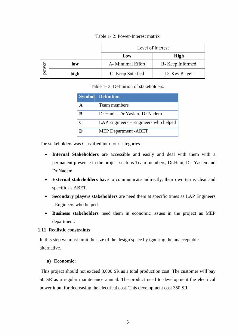
1.10 Project customers and stakeholders
Stakeholders are persons or organizations who are actively involved in the project or
whose interests may be positively or negatively affected by its performance or
completion. They may be categorized as internal, external, or secondary, players, as
business or non-business actors, as proponent or opponent, or as economic, social,
environmental or technical. Table 1- 2 and Table 1- 3 in the next page are shown the
definition of stakeholders.
Page 18
5
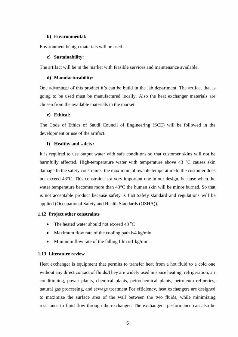
Table 1- 2: Power-Interest matrix
Table 1- 3: Definition of stakeholders.
Symbol Definition
A Team members
B Dr.Hani – Dr.Yasien- Dr.Nadem
C LAP Engineers – Engineers who helped
D MEP Department -ABET
The stakeholders was Classified into four categories
Internal Stakeholders are accessible and easily and deal with them with a
permanent presence in the project such us Team members, Dr.Hani, Dr. Yasien and
Dr.Nadem.
External stakeholders have to communicate indirectly, their own terms clear and
specific as ABET.
Secondary players stakeholders are need them at specific times as LAP Engineers
- Engineers who helped.
Business stakeholders need them in economic issues in the project as MEP
department.
1.11 Realistic constraints
In this step we must limit the size of the design space by ignoring the unacceptable
alternative.
a) Economic:
This project should not exceed 3,000 SR as a total production cost. The customer will bay
50 SR as a regular maintenance annual. The product need to development the electrical
power input for decreasing the electrical cost. This development cost 350 SR.
Page 19
6
b) Environmental:
Environment benign materials will be used.
c) Sustainability:
The artifact will be in the market with feasible services and maintenance available.
d) Manufacturability:
One advantage of this product it‟s can be build in the lab department. The artifact that is
going to be used must be manufactured locally. Also the heat exchanger materials are
chosen from the available materials in the market.
e) Ethical:
The Code of Ethics of Saudi Council of Engineering (SCE) will be followed in the
development or use of the artifact.
f) Healthy and safety:
It is required to use output water with safe conditions so that customer skins will not be
harmfully affected. High-temperature water with temperature above 43 °C causes skin
damage.In the safety constraints, the maximum allowable temperature to the customer does
not exceed 43°C. This constraint is a very important one in our design, because when the
water temperature becomes more than 43°C the human skin will be minor burned. So that
is not acceptable product because safety is first.Safety standard and regulations will be
applied (Occupational Safety and Health Standards (OSHA)).
1.12 Project other constraints
The heated water should not exceed 43 oC
Maximum flow rate of the cooling path is4 kg/min.
Minimum flow rate of the falling film is1 kg/min.
1.13 Literature review
Heat exchanger is equipment that permits to transfer heat from a hot fluid to a cold one
without any direct contact of fluids.They are widely used in space heating, refrigeration, air
conditioning, power plants, chemical plants, petrochemical plants, petroleum refineries,
natural gas processing, and sewage treatment.For efficiency, heat exchangers are designed
to maximize the surface area of the wall between the two fluids, while minimizing
resistance to fluid flow through the exchanger. The exchanger's performance can also be
Page 20
7
affected by the addition of fins or corrugations in one or both directions, which increase
surface area and may channel fluid, flow or induce turbulence. There are many deferent
types of heat exchangers compared to falling film heat exchanger such as:
Double pipe heat exchangers are the simplest exchangers used in industries. On
one hand, these heat exchangers are cheap for both design and maintenance,
making them a good choice for small industries. But on the other hand, low
efficiency of them beside high space occupied for such exchangers in large scales.
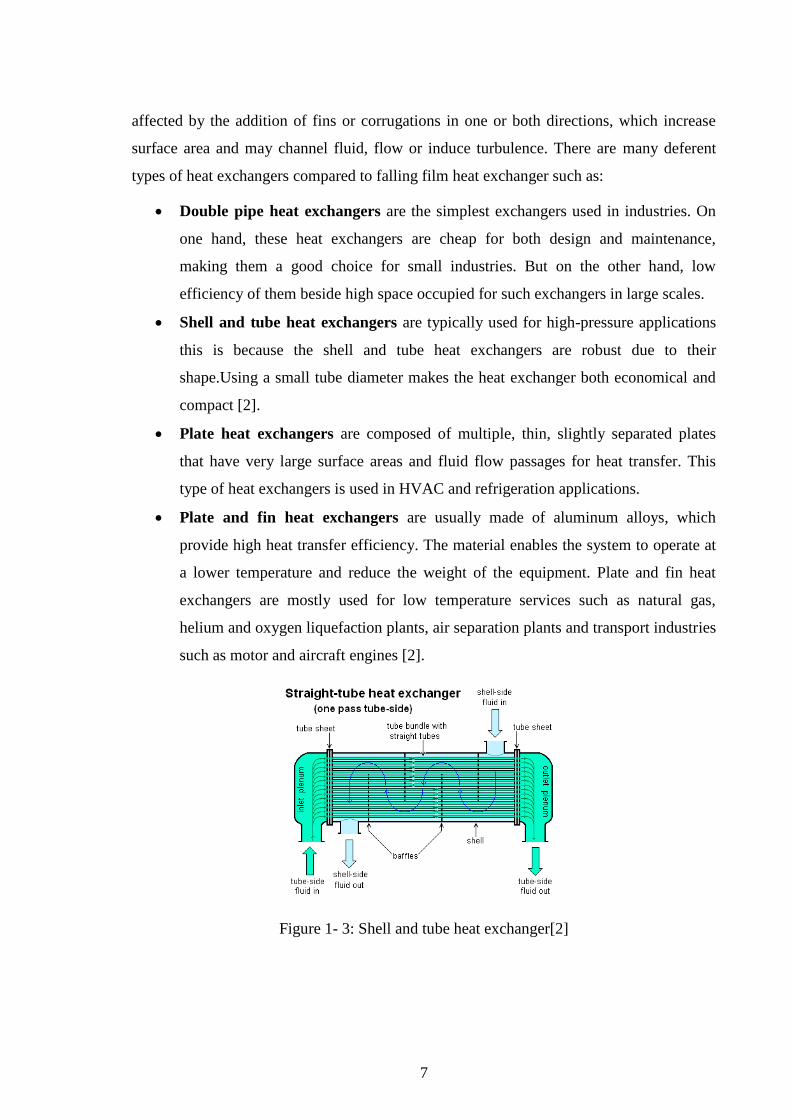
Shell and tube heat exchangers are typically used for high-pressure applications
this is because the shell and tube heat exchangers are robust due to their
shape.Using a small tube diameter makes the heat exchanger both economical and
compact [2].
Plate heat exchangers are composed of multiple, thin, slightly separated plates
that have very large surface areas and fluid flow passages for heat transfer. This
type of heat exchangers is used in HVAC and refrigeration applications.
Plate and fin heat exchangers are usually made of aluminum alloys, which
provide high heat transfer efficiency. The material enables the system to operate at
a lower temperature and reduce the weight of the equipment. Plate and fin heat
exchangers are mostly used for low temperature services such as natural gas,
helium and oxygen liquefaction plants, air separation plants and transport industries
such as motor and aircraft engines [2].
Figure 1- 3: Shell and tube heat exchanger[2]
Page 21
8
Figure 1- 4: Plate heat exchanger[2]
Falling film technique is used in much application, trying to find a manufacturers use this
technique in heat exchanger is difficult. Most of manufacturers use falling film technique
in evaporators and they are used many methods and ways to make this technique and
manufacture it under specific client requirement. For the falling film evaporators and
condensers used in the refrigeration industry, the flow pattern and its role in determining
how the liquid falls from upper to lower tubes is important in determining the so-called
inundation effect for applications in desalination and chemical processing, where sensible
heat transfer is more important, the nature of the falling film flow has a direct impact on
convective heat transfer.
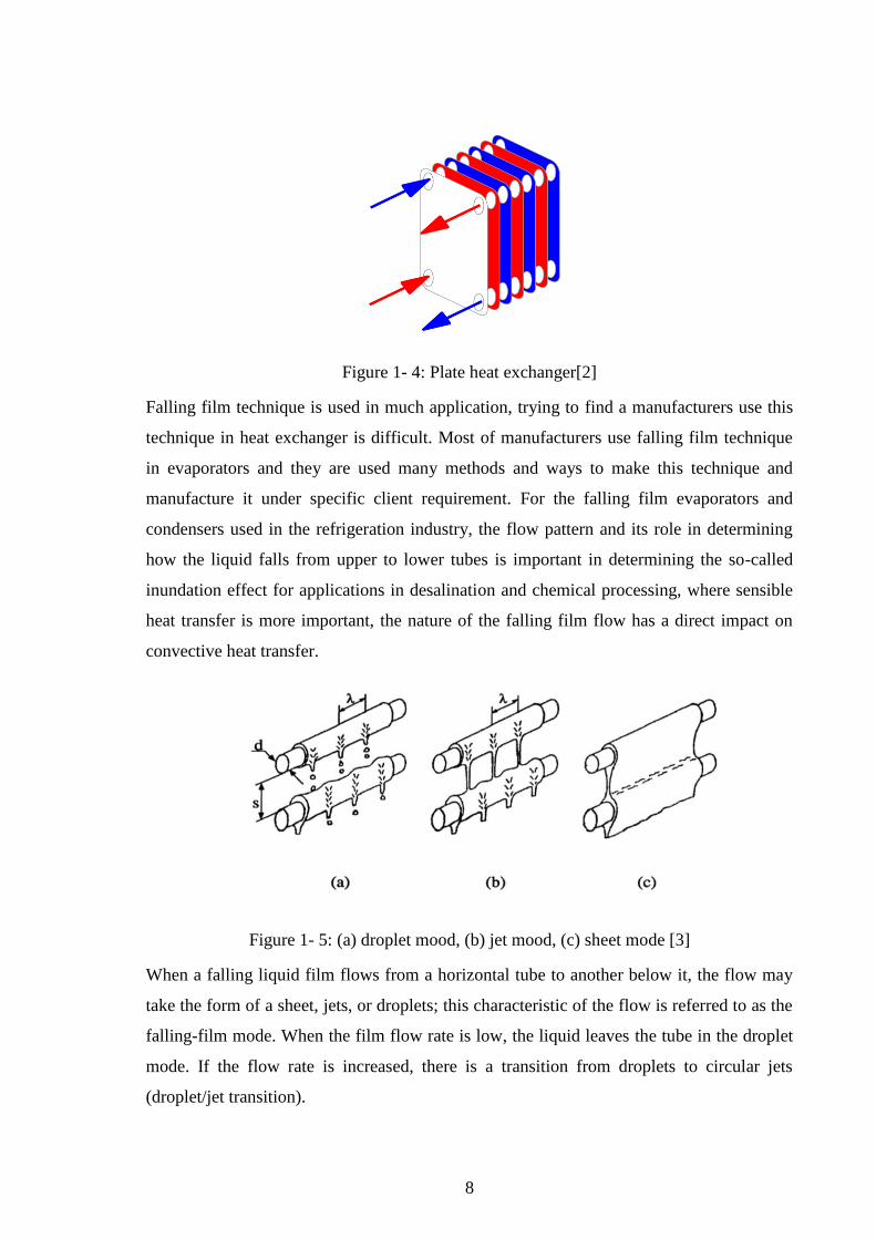
Figure 1- 5: (a) droplet mood, (b) jet mood, (c) sheet mode [3]
When a falling liquid film flows from a horizontal tube to another below it, the flow may
take the form of a sheet, jets, or droplets; this characteristic of the flow is referred to as the
falling-film mode. When the film flow rate is low, the liquid leaves the tube in the droplet
mode. If the flow rate is increased, there is a transition from droplets to circular jets
(droplet/jet transition).
Page 22
9
CHAPTER 2: CONCEPTUAL DESIGN
2.1 Quality Function Deployment (QFD)
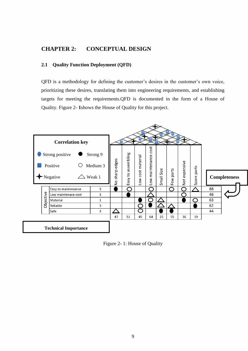
QFD is a methodology for defining the customer‟s desires in the customer‟s own voice,
prioritizing these desires, translating them into engineering requirements, and establishing
targets for meeting the requirements.QFD is documented in the form of a House of
Quality. Figure 2- 1shows the House of Quality for this project.
Figure 2- 1: House of Quality
Correlation key
Technical Importance
Completeness
Criteria
Strong positive Strong 9
Positive Medium 3
Negative Weak 1
Page 23
10
2.2 Major Function
Designing function is about choosing the best alternative. A black box is one of the
techniques that used in this assignment. Other technique used in this assignment is the
transparent box. To show how each function works a Function-Tree mean technique has
been used. Some other techniques used to get the best alternative.
2.3 Design Function
A falling film heat exchanger is about to design with vertical or horizontal tubes.
1) Horizontal
1.1 Tube marital
1.1.1 Titanium
1.1.2 Copper
1.1.3 Iron
1.2 Tube surface
1.2.1 Signal groove
1.2.2 Double groove
1.2.3 Smooth
1.3 Mode
1.3.1 Jet
1.3.2 Sheet jet
1.3.3 Droplet
1.4 Box material
1.4.1 Fiberglass
1.4.2 Iron
1.4.3 Reinforced plastic
2) Vertical
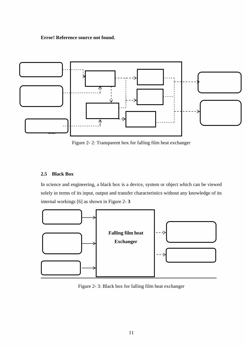
2.4 Transparent Box
Is a method of testing software that tests internal structures or workings of an application,
as opposed to its functionalityIn transparent testing an internal perspective of the system,
as well as programming skills, are required and used to design test cases [5]. The tester
chooses inputs to exercise paths through the code and determine the appropriate outputs.
As shown in Figure 2- 2
Page 24
11
Error! Reference source not found.
2.1.B
2.2.
Figure 2- 2: Transparent box for falling film heat exchanger
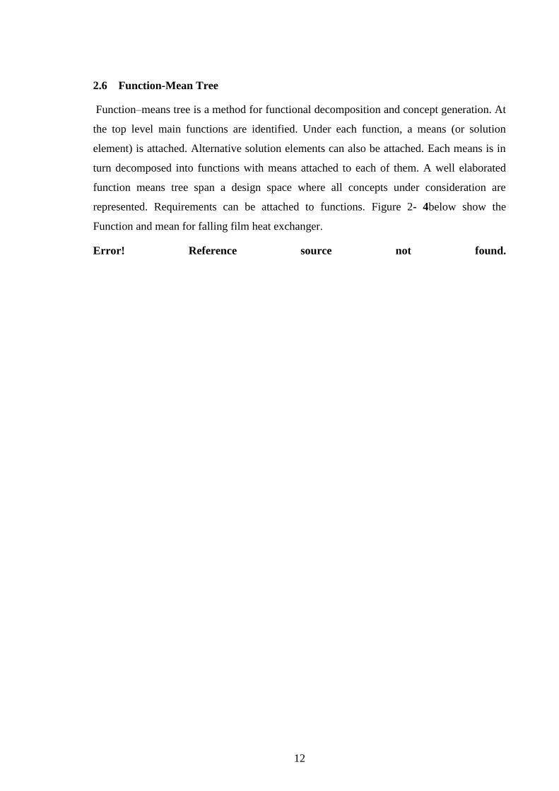
2.5 Black Box
In science and engineering, a black box is a device, system or object which can be viewed
solely in terms of its input, output and transfer characteristics without any knowledge of its
internal workings [6] as shown in Figure 2- 3
Figure 2- 3: Black box for falling film heat exchanger
Power
(Energy)
Control
(information) of
temperature
Hot fluid
Hot fluid
Converge
Power (Energy)
Control of
temperature
(Information)
Hot fluid
Cooling
path
Heat transfer
The second fluid
has been heated
High heat
transfer
coefficient
Marital of
tube
Surface
Of tube
Size of
tube
Falling film heat
Exchanger
Page 25
12
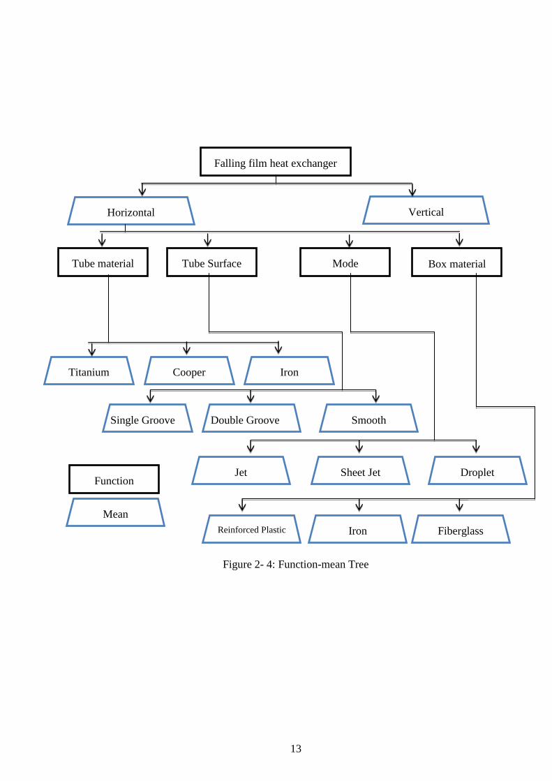
2.6 Function-Mean Tree
Function–means tree is a method for functional decomposition and concept generation. At
the top level main functions are identified. Under each function, a means (or solution
element) is attached. Alternative solution elements can also be attached. Each means is in
turn decomposed into functions with means attached to each of them. A well elaborated
function means tree span a design space where all concepts under consideration are
represented. Requirements can be attached to functions. Figure 2- 4below show the
Function and mean for falling film heat exchanger.
Error! Reference source not found.
Page 26
13
Figure 2- 4: Function-mean Tree
Horizontal Vertical
Box material Tube Surface Tube material Mode
Titanium Iron Cooper
Falling film heat exchanger
Single Groove Double Groove Smooth
Droplet Jet Sheet Jet
Fiberglass
Function
Mean
Reinforced Plastic Iron
Page 27
14
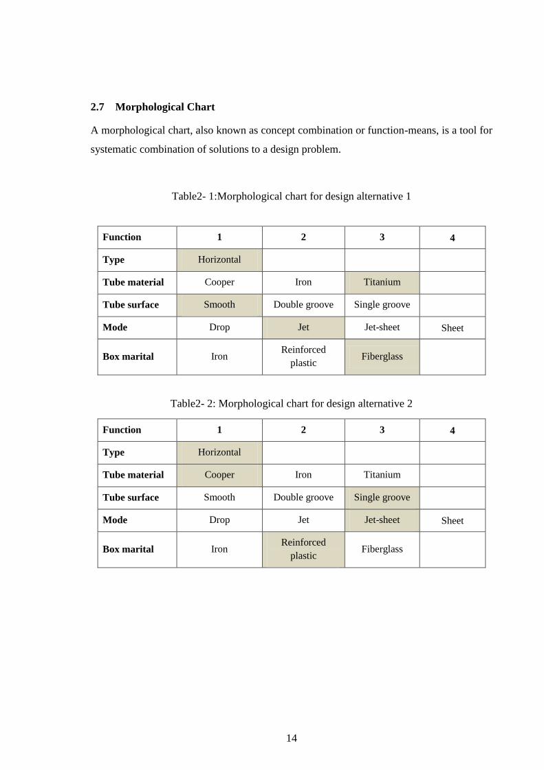
2.7 Morphological Chart
A morphological chart, also known as concept combination or function-means, is a tool for
systematic combination of solutions to a design problem.
Table2- 1:Morphological chart for design alternative 1
Function 1 2 3 4
Type Horizontal
Tube material Cooper Iron Titanium
Tube surface Smooth Double groove Single groove
Mode Drop Jet Jet-sheet Sheet
Box marital Iron Reinforced
plastic Fiberglass
Table2- 2: Morphological chart for design alternative 2
Function 1 2 3 4
Type Horizontal
Tube material Cooper Iron Titanium
Tube surface Smooth Double groove Single groove
Mode Drop Jet Jet-sheet Sheet
Box marital Iron Reinforced
plastic Fiberglass
Page 28
15
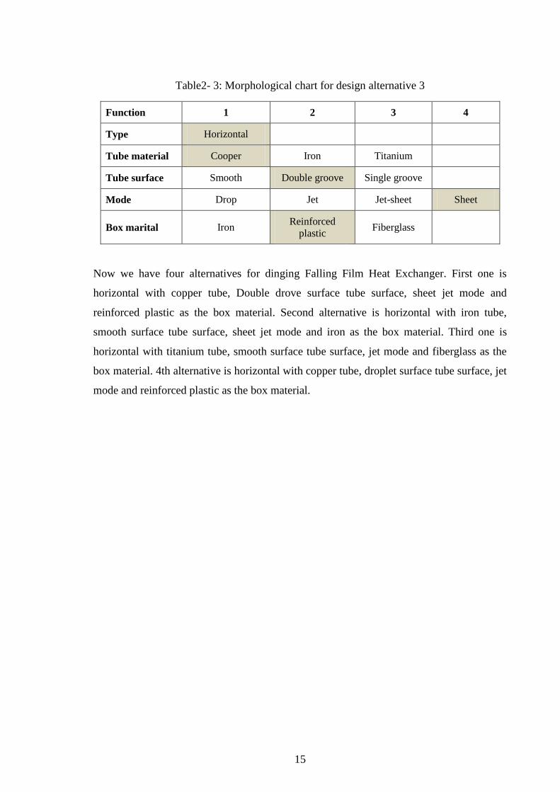
Table2- 3: Morphological chart for design alternative 3
Function 1 2 3 4
Type Horizontal
Tube material Cooper Iron Titanium
Tube surface Smooth Double groove Single groove
Mode Drop Jet Jet-sheet Sheet
Box marital Iron Reinforced
plastic Fiberglass
Now we have four alternatives for dinging Falling Film Heat Exchanger. First one is
horizontal with copper tube, Double drove surface tube surface, sheet jet mode and
reinforced plastic as the box material. Second alternative is horizontal with iron tube,
smooth surface tube surface, sheet jet mode and iron as the box material. Third one is
horizontal with titanium tube, smooth surface tube surface, jet mode and fiberglass as the
box material. 4th alternative is horizontal with copper tube, droplet surface tube surface, jet
mode and reinforced plastic as the box material.
Page 29
16
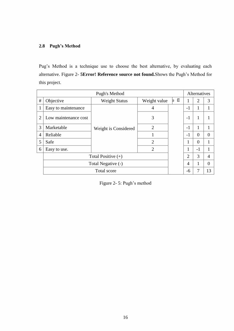
2.8 Pugh’s Method
Pug‟s Method is a technique use to choose the best alternative, by evaluating each
alternative. Figure 2- 5Error! Reference source not found.Shows the Pugh‟s Method for
this project.
Pugh's Method Alternatives
# Objective Weight Status Weight value D a t u m
1 2 3
1 Easy to maintenance
Weight is Considered
4
-1 1 1
2 Low maintenance cost 3 -1 1 1
3 Marketable 2 -1 1 1
4 Reliable 1 -1 0 0
5 Safe 2 1 0 1
6 Easy to use. 2 1 -1 1
Total Positive (+) 2 3 4
Total Negative (-) 4 1 0
Total score -6 7 13
Figure 2- 5: Pugh‟s method
Page 30
17
CHAPTER 3: PROJECT MANAGEMENT
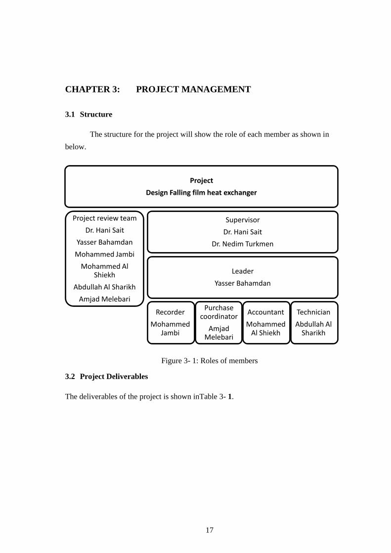
3.1 Structure
The structure for the project will show the role of each member as shown in
below.
Figure 3- 1: Roles of members
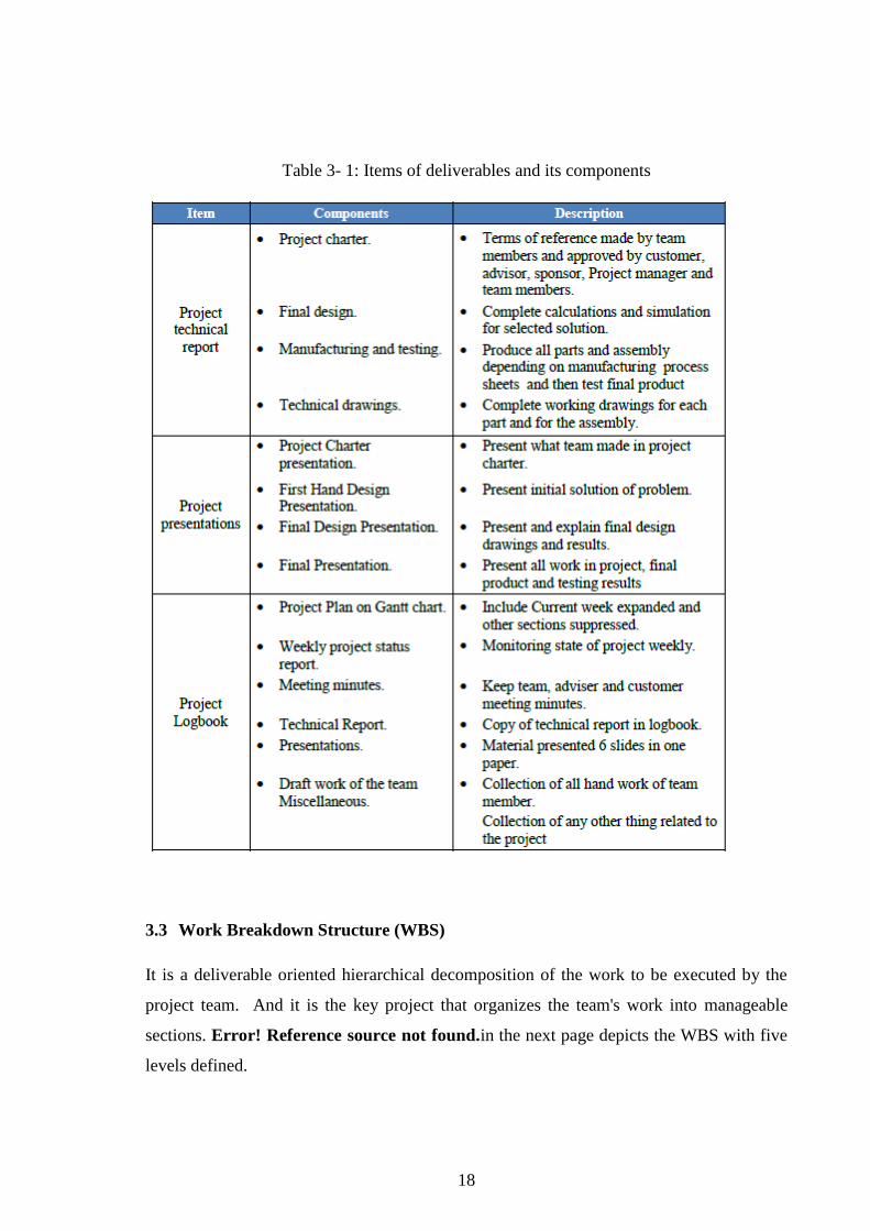
3.2 Project Deliverables
The deliverables of the project is shown inTable 3- 1.
Project
Design Falling film heat exchanger
Project review team
Dr. Hani Sait
Yasser Bahamdan
Mohammed Jambi
Mohammed Al Shiekh
Abdullah Al Sharikh
Amjad Melebari
Supervisor
Dr. Hani Sait
Dr. Nedim Turkmen
Leader
Yasser Bahamdan
Recorder
Mohammed Jambi
Purchase coordinator
Amjad Melebari
Accountant
Mohammed Al Shiekh
Technician
Abdullah Al Sharikh
Page 31
18
Table 3- 1: Items of deliverables and its components
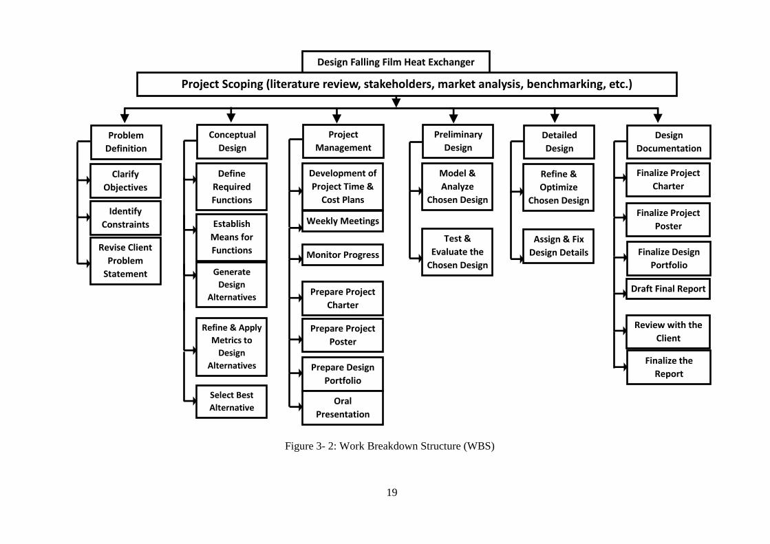
3.3 Work Breakdown Structure (WBS)
It is a deliverable oriented hierarchical decomposition of the work to be executed by the
project team. And it is the key project that organizes the team's work into manageable
sections. Error! Reference source not found.in the next page depicts the WBS with five
levels defined.
Page 32
19
Design Falling Film Heat Exchanger
Problem
Definition
Clarify
Objectives
Identify
Constraints
Revise Client
Problem
Statement
Conceptual
Design
Define
Required
Functions
Establish
Means for
Functions
Generate
Design
Alternatives
Refine & Apply
Metrics to
Design
Alternatives
Select Best
Alternative
Project
Management
Development of
Project Time &
Cost Plans
Weekly Meetings
Monitor Progress
Preliminary
Design
Model &
Analyze
Chosen Design
Test &
Evaluate the
Chosen Design
Detailed
Design
Refine &
Optimize
Chosen Design
Assign & Fix
Design Details
Design
Documentation
Finalize Project
Charter
Finalize Project
Poster
Finalize Design
Portfolio
Project Scoping (literature review, stakeholders, market analysis, benchmarking, etc.)
Draft Final Report
Review with the
Client
Prepare Project
Charter
Prepare Project
Poster
Prepare Design
Portfolio
Oral
Presentation
Finalize the
Report
Figure 3- 2: Work Breakdown Structure (WBS)
Page 33
20
3.4 Project Plan
In this section the approach of each subject regarding the project will be constructed, also
the overall plan using Gantt chart technique will show the deadlines, financial plan and
quality plan of the project will be organized.
3.4.1 Approach
Here we will describe the phases and approach for each element in the project as shown in
Table 3- 2.
Table 3- 2: Approach of phase
Phases Approach
Initiation The Goal Of This Phase Is To Build The Project. All Members Will Start To Do It By
Collecting Information And Requirements.
Planning Using MS Project Program For Project Plan And Actions.
Execution The Team Will Start Alternatives Solution And Selection Design According To
Requirements. Then, Start Analysis, Generating Alternatives, Manufacturing And
Testing.
Page 34
21
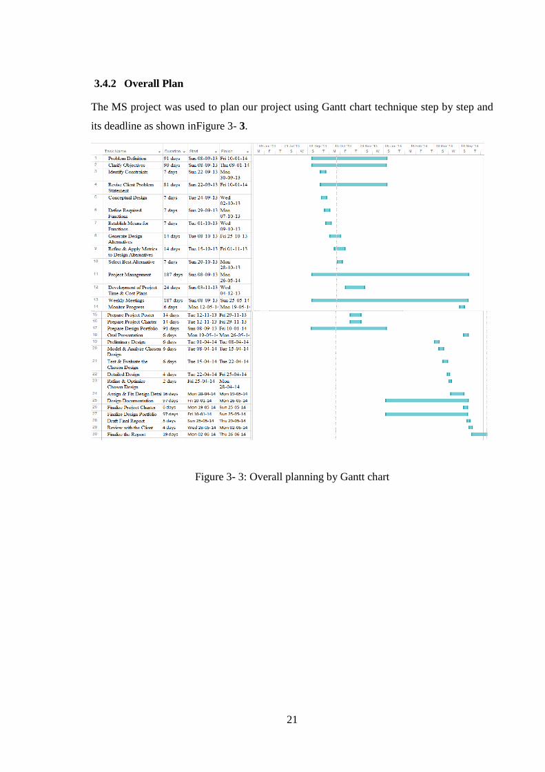
3.4.2 Overall Plan
The MS project was used to plan our project using Gantt chart technique step by step and
its deadline as shown inFigure 3- 3.
Figure 3- 3: Overall planning by Gantt chart
Page 35
22
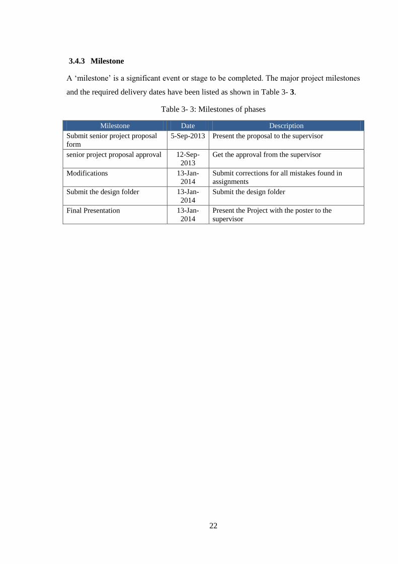
3.4.3 Milestone
A „milestone‟ is a significant event or stage to be completed. The major project milestones
and the required delivery dates have been listed as shown in Table 3- 3.
Table 3- 3: Milestones of phases
Milestone Date Description
Submit senior project proposal
form
5-Sep-2013 Present the proposal to the supervisor
senior project proposal approval 12-Sep-
2013
Get the approval from the supervisor
Modifications 13-Jan-
2014
Submit corrections for all mistakes found in
assignments
Submit the design folder 13-Jan-
2014
Submit the design folder
Final Presentation 13-Jan-
2014
Present the Project with the poster to the
supervisor
Page 36
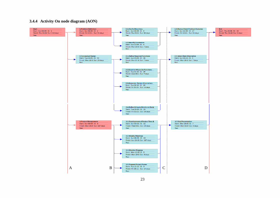
23
3.4.4 Activity On node diagram (AON)
A B C D
Page 37
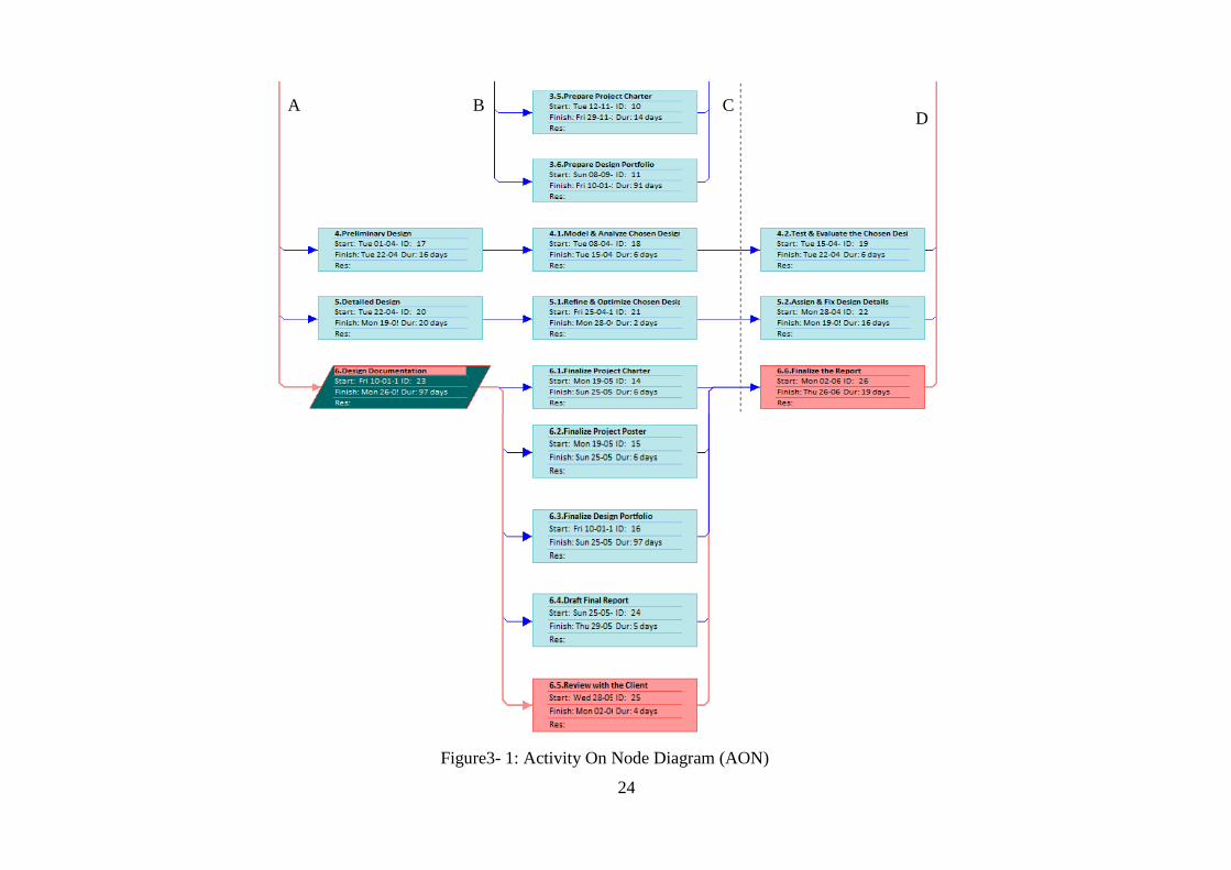
24
Figure3- 1: Activity On Node Diagram (AON)
A B C D
Page 38
25
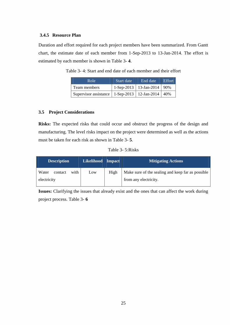
3.4.5 Resource Plan
Duration and effort required for each project members have been summarized. From Gantt
chart, the estimate date of each member from 1-Sep-2013 to 13-Jan-2014. The effort is
estimated by each member is shown in Table 3- 4.
Table 3- 4: Start and end date of each member and their effort
Role Start date End date Effort
Team members 1-Sep-2013 13-Jan-2014 90%
Supervisor assistance 1-Sep-2013 12-Jan-2014 40%
3.5 Project Considerations
Risks: The expected risks that could occur and obstruct the progress of the design and
manufacturing. The level risks impact on the project were determined as well as the actions
must be taken for each risk as shown in Table 3- 5.
Table 3- 5:Risks
Description Likelihood Impact Mitigating Actions
Water contact with
electricity
Low High Make sure of the sealing and keep far as possible
from any electricity.
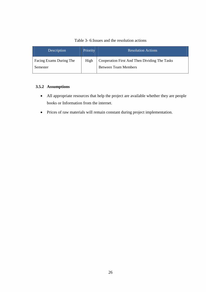
Issues: Clarifying the issues that already exist and the ones that can affect the work during
project process. Table 3- 6
Page 39
26
Table 3- 6:Issues and the resolution actions
Description Priority Resolution Actions
Facing Exams During The
Semester
High Cooperation First And Then Dividing The Tasks
Between Team Members
3.5.2 Assumptions
All appropriate resources that help the project are available whether they are people
books or Information from the internet.
Prices of raw materials will remain constant during project implementation.
Page 40
27
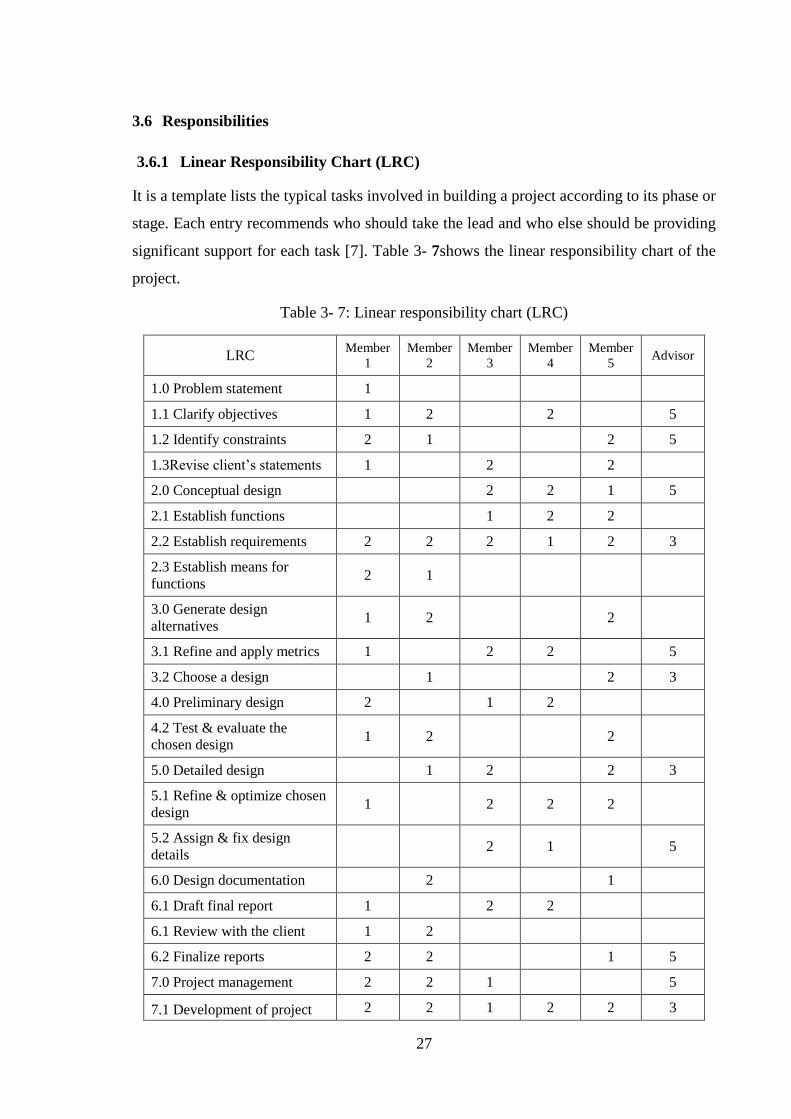
3.6 Responsibilities
3.6.1 Linear Responsibility Chart (LRC)
It is a template lists the typical tasks involved in building a project according to its phase or
stage. Each entry recommends who should take the lead and who else should be providing
significant support for each task [7]. Table 3- 7shows the linear responsibility chart of the
project.
Table 3- 7: Linear responsibility chart (LRC)
LRC Member
1
Member
2
Member
3
Member
4
Member
5 Advisor
1.0 Problem statement 1
1.1 Clarify objectives 1 2
2
5
1.2 Identify constraints 2 1
2 5
1.3Revise client‟s statements 1
2
2
2.0 Conceptual design
2 2 1 5
2.1 Establish functions
1 2 2
2.2 Establish requirements 2 2 2 1 2 3
2.3 Establish means for
functions 2 1
3.0 Generate design
alternatives 1 2
2
3.1 Refine and apply metrics 1
2 2
5
3.2 Choose a design
1
2 3
4.0 Preliminary design 2
1 2
4.2 Test & evaluate the
chosen design 1 2
2
5.0 Detailed design
1 2
2 3
5.1 Refine & optimize chosen
design 1
2 2 2
5.2 Assign & fix design
details 2 1
5
6.0 Design documentation
2
1
6.1 Draft final report 1
2 2
6.1 Review with the client 1 2
6.2 Finalize reports 2 2
1 5
7.0 Project management 2 2 1
5
7.1 Development of project 2 2 1 2 2 3
Page 41
28
LRC Member
1
Member
2
Member
3
Member
4
Member
5 Advisor
time & costs plans
7.2 Weekly meetings 2 1 2 2 5 5
7.3 Monitor progress 1 2 2 2 2 1
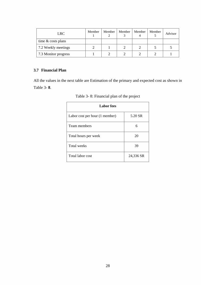
3.7 Financial Plan
All the values in the next table are Estimation of the primary and expected cost as shown in
Table 3- 8.
Table 3- 8: Financial plan of the project
Labor fees
Labor cost per hour (1 member) 5.20 SR
Team members 6
Total hours per week 20
Total weeks 39
Total labor cost 24,336 SR
Page 42
29
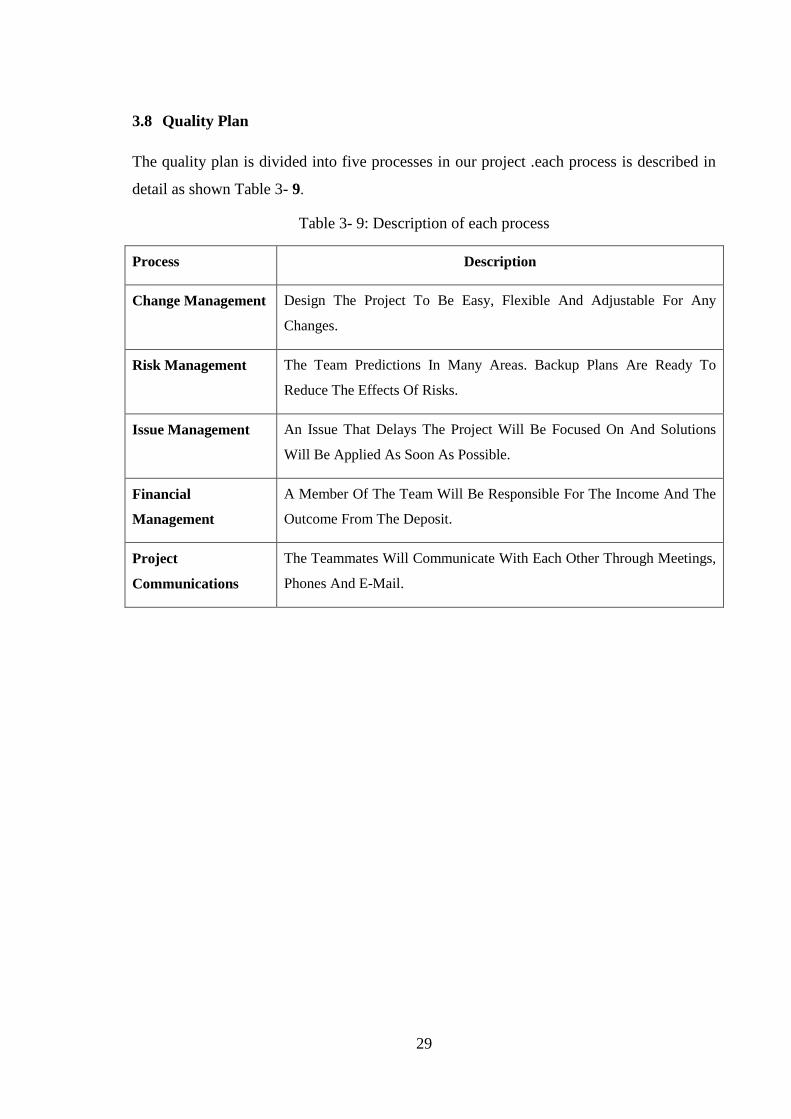
3.8 Quality Plan
The quality plan is divided into five processes in our project .each process is described in
detail as shown Table 3- 9.
Table 3- 9: Description of each process
Process Description
Change Management Design The Project To Be Easy, Flexible And Adjustable For Any
Changes.
Risk Management The Team Predictions In Many Areas. Backup Plans Are Ready To
Reduce The Effects Of Risks.
Issue Management An Issue That Delays The Project Will Be Focused On And Solutions
Will Be Applied As Soon As Possible.
Financial
Management
A Member Of The Team Will Be Responsible For The Income And The
Outcome From The Deposit.
Project
Communications
The Teammates Will Communicate With Each Other Through Meetings,
Phones And E-Mail.
Page 43
30
CHAPTER 4: DESIGN METHODOLOGY
4.1 Introduction
A test box has been built to investigate the problem, it consists of the test section, and
the test section consisted of feed tubes, test tubes and funnel. All the tubes are made of
copper, which has a high thermal conductivity. The feed tube is setup above the test
section, its height is 300 mm the length is 400 mm and the width is 100mm, diameter
holes were drilled 2 mm apart from each other, providing26 holes. The feed tube has
inside and outside diameters of 12.7 mm and 10 mm. It receives liquid from a cooling
path. Three test tubes configured above each other with diameter of 12.7 mm are placed
at a pitch of 130 mm under the feed tubes. They were all held by the supporting box,
which was made of neon transparent. The cooling path gave a capability of adjusting the
temperature to keep it constant. It was used to supply hot water inside the test tubes. A
constant temperature tap water provides pure water to the outside of the test tubes with
different flow rate. Outlet temperature and flow rate of water, inside and outside the test
tubes were recorded. Surface temperature was measured for one tube. Data acquired
was used for temperature measurement.
4.2 Scope and Limitations of the work
This work aims to analyze the heat transfer characteristics and temperature distribution
of specific type of a falling film heat exchanger with horizontal feed tube. The analysis
is limited by the manufacturing and fabricated structures of the test box. The tubes
spacing is changeable and the tubes are connected in series. The type of the used
feeding tube also limits the falling film flow. The low thickness of the tube, make it
difficult to embed the thermocouples in the surface.
4.3 Measuring Techniques
The temperatures of the heated fluid inside the tube and water falling film were
measured by using thermocouples type K. They are fixed in the tubes passageway. The
flow rate of the heated fluid and the water falling film was measured by using calibrated
flow meters.
Page 44
31
4.4 Governing equations
Considering hot fluid inside tube to heat another fluid outside the tube. The thermal
resistance consists of inside convective heat transfer and outside convective heat
transfer.
Consider a hollow grooved cylinder with inner and outer surfaces are being exposed to
fluids at different temperatures. The heat transfer rate in radial direction using Fourier's
law of heat conduction is[8]:
𝑄 =2 𝜋 𝑙 𝑘(𝑇𝑠,1− 𝑇𝑠,2)
ln(𝑟2𝑟1
) (1.1)
From this equation it is evident that for radial conduction in hollow cylinders, the
thermal resistance would be[9]:
𝑅𝑡 ,𝑐𝑜𝑛𝑑 = ln(
𝑟2𝑟1
)
2 𝜋 𝑙 𝑘 (1.2)
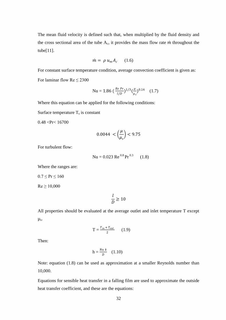
In this case the heat transfer is carried out as that composite cylinder. The heat transfer
may be expressed as shown in the following Figure 4- 1
Figure 4- 1 Thermal resistance for the cylinder.
𝑞𝑟 = 1
12 𝜋 𝑟1 𝑙+
ln(𝑟2𝑟1
)
2 𝜋 𝑘 𝑙+
1
22 𝜋 𝑟2 𝑙 (1.3)
The flow in a circular tube is either laminar or turbulent depending on the value of
Reynolds number. The Reynolds number for a flow in a circular tube is defined as [10]:
𝑅𝑒 = 𝜌 𝑢𝑚𝐷
𝜇 (1.4)
Where um is the mean fluid velocity over the cross section and D is the wetted
perimeter. In a fully developed flow, the critical Reynolds number corresponding to the
beginning of turbulence is:
ReD,c ≈ 2300 (1.5)
Page 45
32
The mean fluid velocity is defined such that, when multiplied by the fluid density and
the cross sectional area of the tube Ac, it provides the mass flow rate 𝑚 throughout the
tube[11].
𝑚 = 𝜌 𝑢𝑚𝐴𝑐 (1.6)
For constant surface temperature condition, average convection coefficient is given as:
For laminar flow Re ≤ 2300
Nu = 1.86 ( 𝑅𝑒 𝑃𝑟
𝑙/𝐷)1/3(
𝜇
𝜇𝑠)0.14 (1.7)
Where this equation can be applied for the following conditions:
Surface temperature Ts is constant
0.48 <Pr< 16700
0.0044 < 𝜇
𝜇𝑠 < 9.75
For turbulent flow:
Nu = 0.023 Re 0.8
Pr 0.3
(1.8)
Where the ranges are:
0.7 ≤ Pr ≤ 160
Re ≥ 10,000
𝑙
𝐷≥ 10
All properties should be evaluated at the average outlet and inlet temperature T except
µs.
T = 𝑇𝑖𝑛 + 𝑇𝑜𝑢𝑡
2 (1.9)
Then:
h = 𝑁𝑢 𝑘
𝐷 (1.10)
Note: equation (1.8) can be used as approximation at a smaller Reynolds number than
10,000.
Equations for sensible heat transfer in a falling film are used to approximate the outside
heat transfer coefficient, and these are the equations:
Page 46
33
For sheet mode[12]:
Nu = 2.194 Ref 0.28
Pr 0.14
Ar - 0.20
(s/d) 0.07
(1.11)
For jet mode[13]:
Nu = 1.378 Ref 0.42
Pr 0.26
Ar - 0.23
(s/d) 0.08
(1.12)
For droplet mode[14]:
Nu = 0.113 Ref 0.85
Pr 0.85
Ar – 0.27
(s/d) 0.04
(1.13)
The liquid properties were evaluated at film temperature Tf.
Where:
Nu: modified Nusselt number = (𝜈2
𝑔)1/3
𝑘 (1.14)
Ref: film Reynolds number = 2 Г/µ (1.15)
Pr: Prandtle number = 𝐶𝑝 𝜇
𝑘 (1.16)
Ar: Archimedes number based on tube diameter = 𝑑3𝑔
𝜈2 (1.17)
Page 47
34
CHAPTER 5: THERMAL SIZING OF FALLING FILM HEAT
EXCHANGER
5.1 Introduction
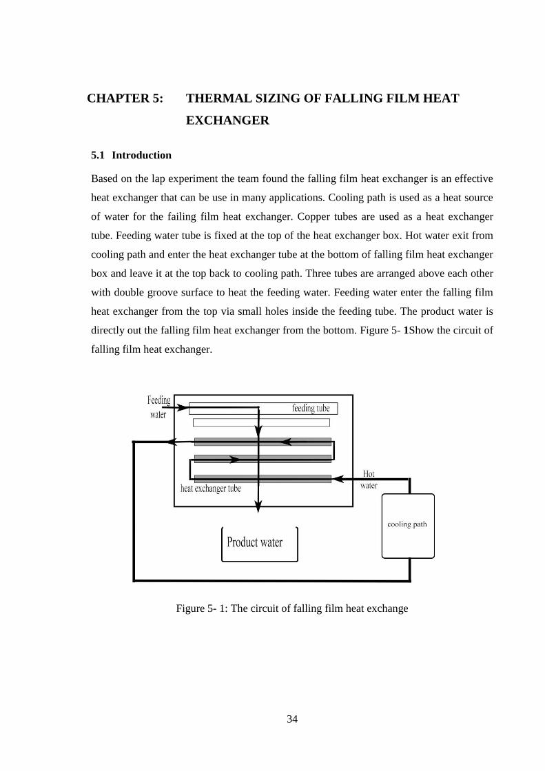
Based on the lap experiment the team found the falling film heat exchanger is an effective
heat exchanger that can be use in many applications. Cooling path is used as a heat source
of water for the failing film heat exchanger. Copper tubes are used as a heat exchanger
tube. Feeding water tube is fixed at the top of the heat exchanger box. Hot water exit from
cooling path and enter the heat exchanger tube at the bottom of falling film heat exchanger
box and leave it at the top back to cooling path. Three tubes are arranged above each other
with double groove surface to heat the feeding water. Feeding water enter the falling film
heat exchanger from the top via small holes inside the feeding tube. The product water is
directly out the falling film heat exchanger from the bottom. Figure 5- 1Show the circuit of
falling film heat exchanger.
Figure 5- 1: The circuit of falling film heat exchange
Page 48
35
5.2 Main technical and operation data
The average quantity of domestic water is 40 -30 lit/day in Saudi Arabia [4]
.The following
information includes the main technical specifications and operating data:
Feeding water tube diameter = 12.7 mm
Heat exchanger tube diameter = 12.7 mm
Heat exchanger tube length = 135 mm
Number of heat exchanger tube = 3
Total area of heat exchanger tube (Adg) = 0.041 m2
Inlet temperature of hot water (Tcp,i) = 80 C
Feed water mas flow rate (mff ) = 0.043 kg/s
Hot water mass flow rate (mcp) = 0.054 kg/s
5.3 Heat transfer rate for falling film
The sensible heat, Qff, of falling film is given by [15]:
Qff = mffCp (Tff,o – Tff,i)
Where mff = 0.0087 kg/s is the mass flow rate of feeding water, Cp = 4182 j/kg.k, Tff,o =
49.8 °C is the falling film temperature at the outlet and Tff,I = 22.7 °C is the falling film
temperature at the inlet. The Qff =985.99 w for the drop mode in double groove surface.
5.4 Heat transfer rate for cooling path
The sensible heat, Qcp, of cooling path is given by:
Qcp = mcpCp (Tcp,i – Tcp,o)
Where mcp = 0.054 kg/s is the mass flow rate of feeding water, Cp = 4195 j/kg.k, Tcp,o = 77
°C is the cooling path temperature at the outlet and Tcp,i = 80 °C is the cooling path
temperature at the inlet. The Qcp = 679.59 w for the drop mode in double groove surface.
5.5 Heat transfer rate ratio
The heat transfer rate ratio is given by:
Qff / Qcp
Page 49
36
Where Qff = 985.99 w is the heat transfer rate of falling film and Qcp =679.59 w is the heat
transfer rate of cooling path. The heat transfer ratio Qff / Qcp = 1.46
5.6 Overall heat transfer of falling film
The overall heat transfer of falling film is given by[16]:
U = 𝑄𝑓𝑓
𝐴𝑑𝑔 ∗∆𝑇𝑙𝑚
Where
ΔTlm = Tcp ,o−Tff ,i −(Tcp ,i−Tff ,o)
𝑙𝑛 Tcp ,o−Tff ,i
(Tcp ,i−Tff ,o )
ΔTlm= 41.1°C, Qff = 985.99 w is the heat transfer rate of falling film and Adg=0.0177 m2 is
total area of double groove surface. U= 1351.07 W/m2. K is the overall heat transfer of
falling film for drop mode.
5.7 Nusselt number of falling film
Nusselt number of falling film given by [17]:
Nu = U x D
𝑘
Where U = 1351.07 W/m2. K is the overall heat transfer, D= 0.0127m is the tube diameter
and k = 0.64W/m.K is the thermal conductivity of falling film. Nu= 26.81 for the falling
film.
5.8 Reynolds number of falling film
Reynolds number of falling film is given by [18]:
Re = 2 x Γ
𝜇
Where Γ= 0.0644 kg/s.m is the mass flow rate per unit length and μ= 0.000577 N.s/m2 is
the dynamic viscosity of falling film. Re = 223.377 for the falling film at drop mode.
Page 50
37
CHAPTER 6: DESIGN OPTIMAZITION
6.1 Introduction
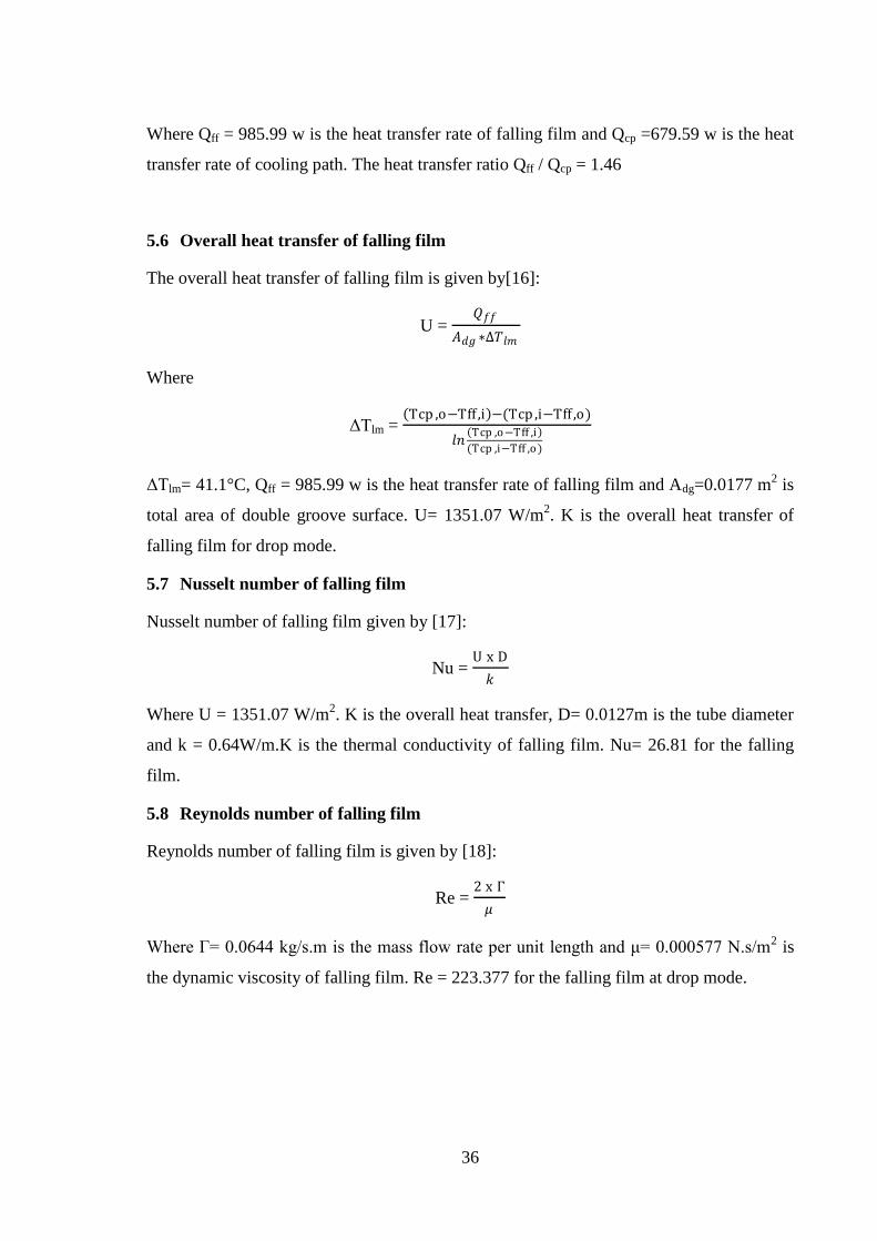
This chapter presents the design optimization of falling film heat exchanger. Based on the
experiment the mode of falling film is determent. Falling film heat exchanger has five
different mode drop, drop-jet, jet, jet-sheet and sheet each mode give a different outlet
temperature. Based on project constraint the outlet temperature dose not exceeds 43 C for
domestic uses.
6.2 Selecting falling film mode
Based on tow main things the falling film mode well be determined the outlet temperature
and the water flow rate. Three modes are achieved the project constraint jet, jet-sheet and
sheet as shown in Table 6- 1
Table 6- 1: Results of double groove surface
Page 51
38
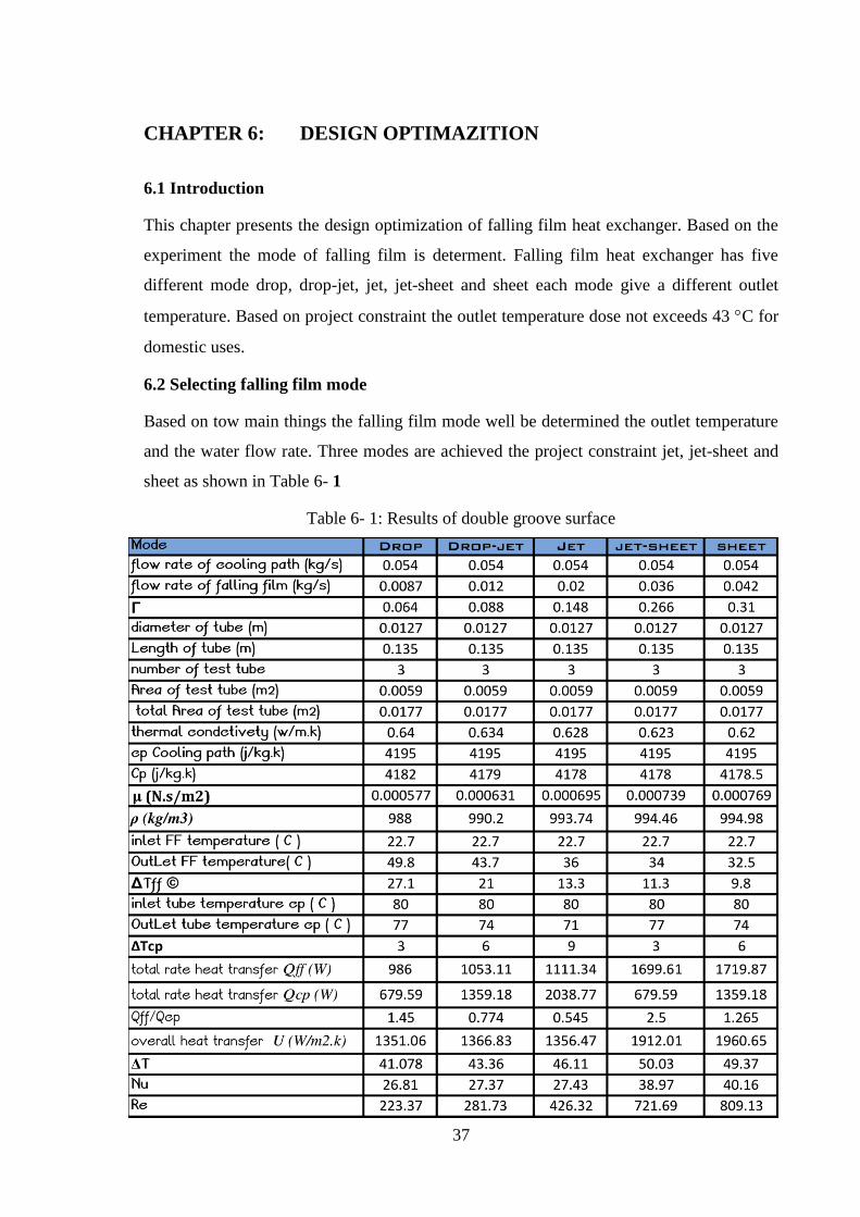
Figure 6- 1: Relation between Tff.out and flow rate
Figure 6- 2: Relation between Q and water flow rate
drop mode
drop-jet mode jet mode
jet-sheet mode
sheet mode
0
10
20
30
40
50
60
0 0.008 0.016 0.024 0.032 0.04 0.048
Tff,out
(c)
m (kg/s)
drop mode
drop-jet mode
jet mode
jet-sheet mode
sheet mode
0
200
400
600
800
1000
1200
1400
1600
1800
2000
0 0.008 0.016 0.024 0.032 0.04 0.048
Q (w)
m (kg/s)
Page 52
39
drop mode
drop-jet mode
jet mode
jet-sheet mode
sheet mode
0
5
10
15
20
25
30
35
40
45
0 100 200 300 400 500 600 700 800 900
Nue
Re
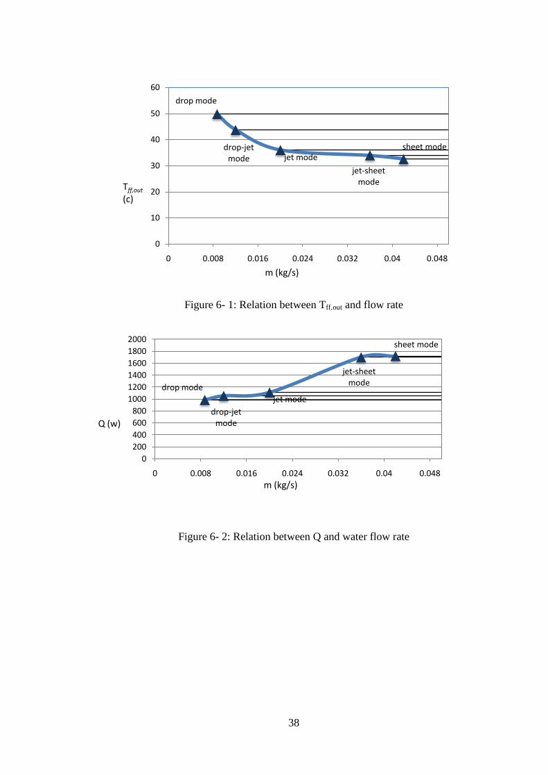
Figure 6- 3: Relation between Nue and Re
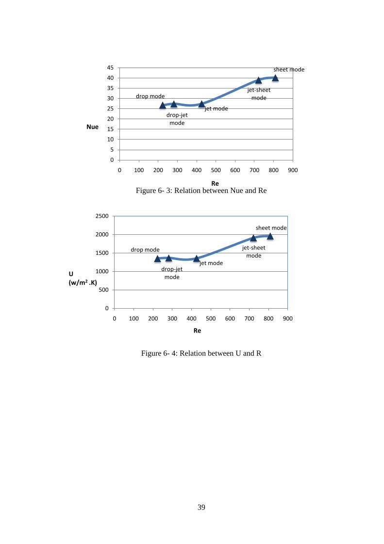
Figure 6- 4: Relation between U and R
drop mode
drop-jet mode
jet mode
jet-sheet mode
sheet mode
0
500
1000
1500
2000
2500
0 100 200 300 400 500 600 700 800 900
U(w/m2 .K)
Re
Page 53
40
CHAPTER 7: EXPERAMNITAL SETUP
7.1 Introduction
In this project a falling film heat exchange is about to design, with a specific condition
of falling. This project divided into series chapters, this chapter supposes to explain how
to manufacture this prototype of heat exchange. In order to reach the best design,
several techniques have been used. Such as brine storming, Linear Responsibility Chart
and other technique are applied. Then to selecting the best alternative we use
Morphological Chart and Pugh‟s method.
7.2 Experimental methodology
The test box is designed and fabricated to increase the water temperature. A cooling
path is used to produces high temperature fluid. In the beginning the water will comes
from tap water with constant temperature. Then it will collect in the feed tube to start
forming the sheet jet. In the meantime the cooling path will heat up the internal tubes,
by pumping a high temperature fluid inside those tubes. Then a falling film will form to
transfer heat between the tubes surface and water. Finally the water will collect in the
tank.
7.3 Design setup
7.3.1 Design properties
For good results we chose a copper tube for the internal horizontal tubes, which we
name it a test tube, fiberglass as the box material and double groove for the internal
tubes surface. After studying the falling form, we decide to set the falling as a sheet jet.
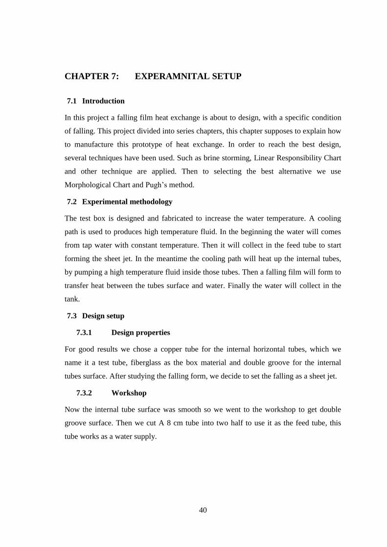
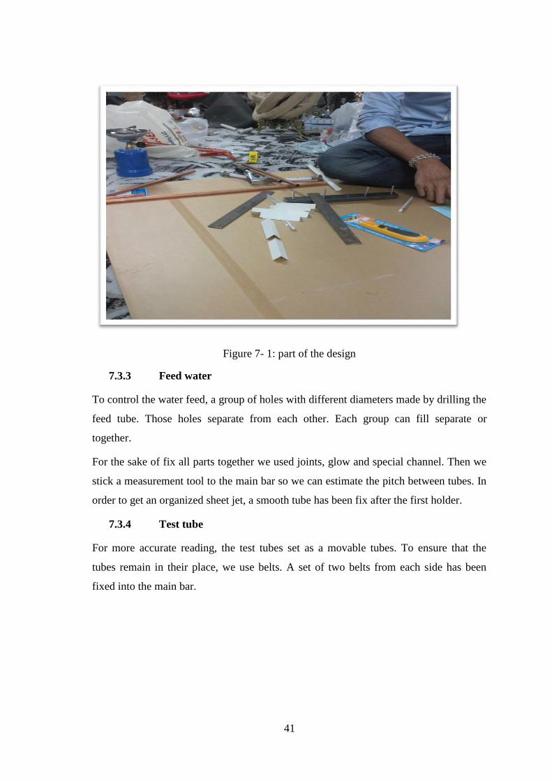
7.3.2 Workshop
Now the internal tube surface was smooth so we went to the workshop to get double
groove surface. Then we cut A 8 cm tube into two half to use it as the feed tube, this
tube works as a water supply.
Page 54
41
Figure 7- 1: part of the design
7.3.3 Feed water
To control the water feed, a group of holes with different diameters made by drilling the
feed tube. Those holes separate from each other. Each group can fill separate or
together.
For the sake of fix all parts together we used joints, glow and special channel. Then we
stick a measurement tool to the main bar so we can estimate the pitch between tubes. In
order to get an organized sheet jet, a smooth tube has been fix after the first holder.
7.3.4 Test tube
For more accurate reading, the test tubes set as a movable tubes. To ensure that the
tubes remain in their place, we use belts. A set of two belts from each side has been
fixed into the main bar.
Page 55
42
Figure 7- 2:Ddouble groove tube
7.3.5 Heating loop
A fixable hose has been used to complete the cycle. Those hose will not deal with high
temperature or pressure, so we used a normal hose. Those hose work to deliver the
water to each test tube inside the box.
7.3.6 Water outlet
In the end of the box a funnel has been blasted. This funnel function is colleting the
heated water and delivered to the tank.
Page 56
43
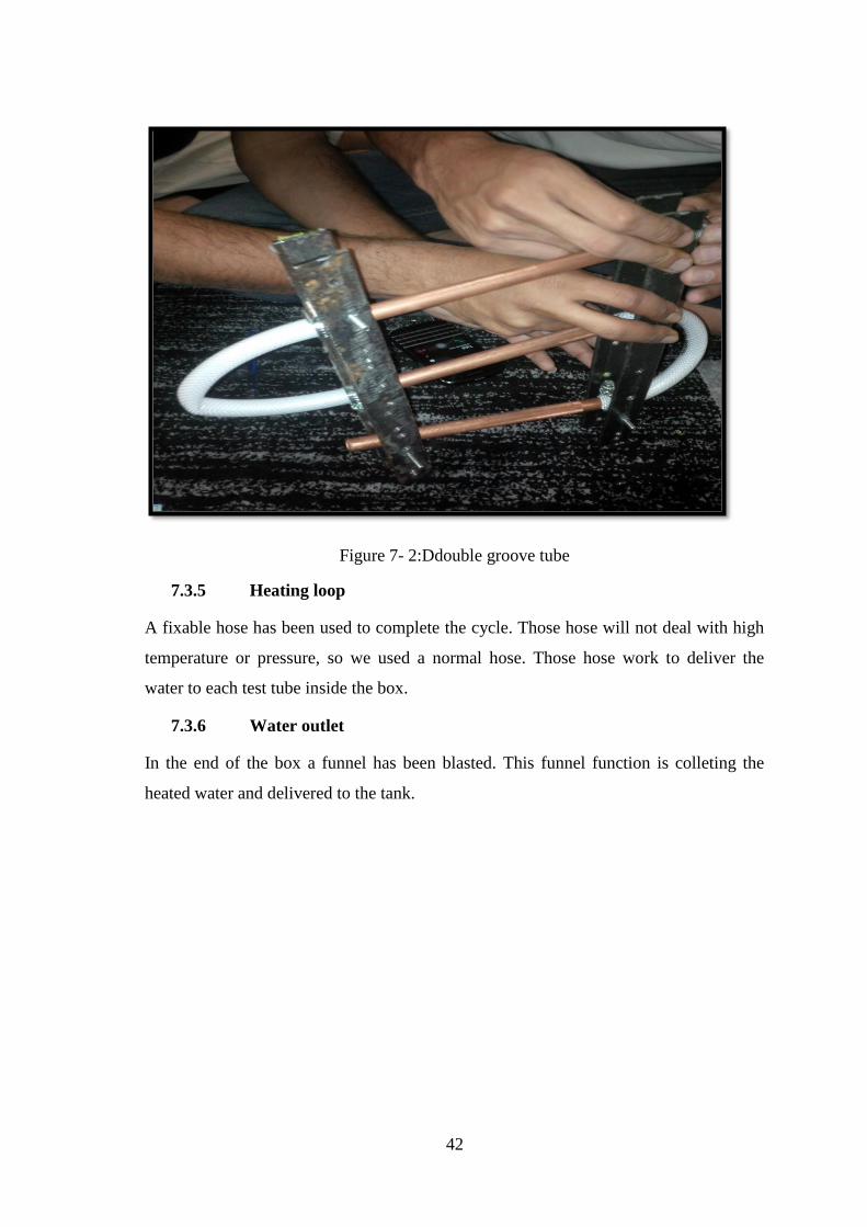
Figure 7- 3:prototype of heat exchange
7.4 Design dimensions
This test box made of fiberglass, which is a transparent sheet (for falling film and heat
transfer) of 10 cm thickness, Test box inside dimensions 40x30x10 cm. The feed tube
has a 12.7 mm diameter and 13.5 cm long. For this experimental we use a cupper tube
as the test tube with 12.7 mm diameter and 13.5 cm long. To ensure continuous heat
transfer we chose cooling path. In order to fix the test tube two bars are blasted.
7.5 Measurement
After assembly and arrangement the prototype parts together, we have to check the
accurate of our project. In order to prove that the heat exchange it woke well a set of
thermo couples and flow meter are fix to the prototype. We have measure the feed water
and compared it with the outlet water.
Page 57
44
CHAPTER 8: PROJECT EVALUATION
On this chapter, the impacts of the falling film heat exchanger will be discussed. These
impacts include impact analysis, economic, potential, environmental and social.
8.1 Global impact
These type heat exchangers can be used as replacement of the some other type of heat
exchangers. In this case it may have share in global market.
8.2 Economic impact
Economically the falling film heat exchanger can add a new production line in industry of
heat exchanger in local and global economy that contributes to increase the need of
employees, whichincrease in gross domestic product and also can decrease the
unemployment rate in the country. On the other hand using falling film heat exchangers
can reduce the operational and maintenance cost that reduce the need of employees.
Politicallyall the industrial projects in Saudi Arabia supported by the government.
8.3 Environmental impact
Falling film heat exchangers are innocuous to the environment; there are no harmful
emissions which reduce the influence ofglobal warming also the falling film heat
exchanger not need to pumps power because the device depend on gravity that mean no
energy loss can effect on the surrounding environment.
8.4 Social impact
With adding a new production line in industry field can provides job opportunities, which
can reduce unemployment rate in the country. Falling film heat exchanger can save money
because there is no need to pumps power and low cost of operational and maintenance
process which can reduce the electricity bills for the citizens.
Page 58
45
CHAPTER 9: CONCOLUSION
A heat exchanger with falling film technique has been designed. This artifact designed
based on several studies. There were special constrains to take about it in this design. Such
as the heated water should not exceed 43 oC, maximum flow rate of the cooling path is 4
kg/min and minimum flow rate of the falling film is 1 kg/ min.A test box has been
designed, it consists of the test section, and the test section consisted of feed tubes, test
tubes and funnel. All the tubes are made of copper, which has a high thermal conductivity.
The feed tube is setup above the test section, its height is 300 mm the length is 400 mm
and the width is 100 mm, diameter holes were drilled 2 mm apart from each other,
providing 26 holes. The feed tube has inside and outside diameters of 12.7 mm and 10 mm.
It receives liquid from a cooling path. Three test tubes configured above each other with
diameter of 12.7 mm are placed at a pitch of 130 mm under the feed tubes. They were all
held by the supporting box, which was made of neon transparent. The cooling path gave a
capability of adjusting the temperature to keep it constant. It was used to supply hot water
inside the test tubes. A constant temperature tap water provides pure water to the outside of
the test tubes with different flow rate. Outlet temperature and flow rate of water, inside and
outside the test tubes were recorded. Surface temperature was measured for one tube. Data
acquired was used for temperature measurement.The average quantity of domestic water is
40 -30 lit/day in Saudi Arabia [11]
. The following information includes the main technical
specifications and operating data:Feeding water tube diameter = 12.7 mm, heat exchanger
tube diameter = 12.7 mm, heat exchanger tube length = 135 mm, number of heat
exchanger tube = 3 tubes, total area of heat exchanger tube (Adg) = 0.041 m2, inlet
temperature of hot water (Tcp,i) = 80 C, feed water mas flow rate (mff ) = 0.043 kg/s, hot
water mass flow rate (mcp) = 0.054 kg/s.
We had been through many steps until we were able to finish this project. We started with
the project charter and the agreement with the customer, then we moved on to overall
planning like constrains for the project, and using many techniques to decide how the
project is going to be.
In the experimental design the team faced variable problems. In order to solve those
problems, the team forced to change the prototype several time, into a new and better one
Page 59
46
with more improvement in each time. The last design was apple to reach to customer
requirements. The last step was getting the product reading, so we run the prototype three
times, now we can calculate the average to reach the best reading.
After finishing this project, the team learns so many things. For example, now each
member understands the member responsibility to his team members. Also the ability of
dealing with engineering problem has been improved.
Page 60
47
REFERENCES
[1]: http://www.hcheattransfer.com/fouling1.html
[2]:http://en.wikipedia.org/wiki/Heat_exchanger
[3]: Hani. H.W. Sait “Experimental investigation on freezing of falling film” pp11, 1999
[4]:http://www.alhayat-j.com/newsite/details.php?opt=3&id=140680&cid=2257
[5]: http://en.wikipedia.org/wiki/White-box_testing.
[6]:http://en.wikipedia.org/wiki/Black_box
[7]: http://www.maxwideman.com/papers/lrc/intro.htm
[8]: Hani. H.W. Sait “Experimental investigation on freezing of falling film” pp13, 1999
[9]: Hani. H.W. Sait “Experimental investigation on freezing of falling film” pp13, 1999
[10]: Hani. H.W. Sait “Experimental investigation on freezing of falling film” pp16, 1999
[11]: Hani. H.W. Sait “Experimental investigation on freezing of falling film” pp16, 1999
[12]: Hani. H.W. Sait “Experimental investigation on freezing of falling film” pp18, 1999
[13]: Hani. H.W. Sait “Experimental investigation on freezing of falling film” pp18, 1999
[14]: Hani. H.W. Sait “Experimental investigation on freezing of falling film” pp18, 1999
[15]: Hani. H.W. Sait “Heat Transfer Characteristics and Temperature Distribution of
Falling Film over Horizontal Hot Tube Arrays “ pp 27, 2012
[16]: Hani. H.W. Sait “Heat Transfer Characteristics and Temperature Distribution of
Falling Film over Horizontal Hot Tube Arrays “ pp 27, 2012
[17]: Hani. H.W. Sait “Heat Transfer Characteristics and Temperature Distribution of
Falling Film over Horizontal Hot Tube Arrays “ pp 28, 2012
[18]: Hani. H.W. Sait “Heat Transfer Characteristics and Temperature Distribution of
Falling Film over Horizontal Hot Tube Arrays “ pp 28, 2012