7 Abstract—underwater acoustic communications presents unique challenges that are being overcome with advances in signal processing algorithms and related hardware technologies. The accurate simulation and performance comparison of various algorithms is essential for building an optimized and robust communications system. This paper describes part of a project designed , based on the results obtained from practical measurements in The Persian Gulf, to examine an underwater acoustic communication system in The Persian Gulf. Transmitted data are acoustic signals to which for more safety in transmission and low frequency bandwidth, a cryptography algorithm and speech coding are applied. In transmitter, quadrature phase shift keying (QPSK) signaling is employed to make efficient use of the available channel bandwidth. In this case, data are transmitted at a rate of 2.4kbps with a carrier frequency of 27 kHz for a maximum range of 2km. In the channel modeling, a comprehensive model for short-range shallow water acoustic channel has been used whose the mathematical modeling of the multipath effects is based on the ray tracing method. In the receiver, decision feedback equalizer (DFE) is applied. Index Terms —Underwater Acoustic Communication, Persian Gulf, Linear Prediction Coder-10, Decision Feedback Equalizer, Rivest Cipher, QPSK Modulation . I.I NTRODUCTIONThe need for underwater wireless communications exists in applications such as collection of scientific data recorded at ocean-bottom stations and by unmanned underwater vehicles, speech transmission between divers, etc. UWC can be established by transmission of acoustic waves. Radio waves are of little use because they are severely attenuated, while optical waves suffer from scattering and need high precision in pointing the laser beams. Seawater acts as an acoustic waveguide in which sound waves travel. T he sound channel, as Manuscript received April 4, 2011. A. Doosti Aref was with Malek-Ashtar University of Technology, Tehran, Iran. E-mail: doosti.aref@ ieee.org. M. J. Jannati was with the University of Science and Technology, Tehran, Iran. E-mail: [email protected]. V. Tabataba Vakili is with the Electrical Engineering Department, University of Science and Technology, Tehran, Iran. E-mail: [email protected]. a sound waveguide, is a channel with random parameters; however, this does not mean that its behaviour is unpredictable. The most important characteristic of the seawater is its inhomogeneous nature, which on the whole, can be classified into regular and random varieties. Regularvariations of sound speed in different layers of water lead to the formation of sound channels and this phenomenon facilitates long distance sound propagation. Random inhomogeneities cause the scattering of sound waves and result in sound field fluctuations. This paper is organized as follows. In the second section, transmitter is designed. Because of the strong frequency attenuation, channel bandwidth is limited, therefore in transmitter, we have used LPC-10 (LinearPrediction Coder-10) algorithm to compress speech signal. After that, for more safety in transmission, RC5 (Rivest Cipher) cryptography algorithm has been used to encrypt data. Then, for reduction of bit error rate (BER), channel coding is used. In the last section of transmission, data is modulated. In the third section, a new model for the Persian Gulf channel has been used that we have deeply described it in [1]. In the fourth section, the block diagram of the receiver and its performance are discussed. Finally, the simulation results related to the transmitter, the devised channel and the receiver in the Persian Gulf are presented. II.TRANSMITTEROn the basis of extensive laboratory and field experiments and the results obtained from deferent simulations, to improve the bandwidth efficiency, using the coherent modulation methods such as Quadrature Amplitude Modulation (QAM) and phase shift keying (PSK) is the best approach in underwater operations [2]. Depending on the method forcarrier synchronization, phase-coherent systems fall into two categories; differentially coherent and purely phase coherent. The advantage of using differentially coherent detection is the simple carrier recovery which it allows. Its disadvantage is performance loss as compared to coherent detection. While bandwidth-efficient methods have successfully been tested on a variety of channels, the real-time systems have mainly been implemented for applications in vertical and very short range channels, where little multipath is observed and the Design and Analysis of Low Frequency Transmitter and Receiver for an Insecure Shallow W ater Acoustic Channel of the Persian GulfA. Doosti Aref, M. J. Jannati, V. Tabata ba Vakili Cyber Journals: Multidisciplinary Journals in Science and Technology, Journal of Selected Areas in Telecommunications (JSAT), April Edition, 2011
Transcript
8/6/2019 Design and Analysis of Low Frequency Transmitter and Receiver for an Insecure Shallow Water Acoustic Channel of …
Abstract — underwater acoustic communications presentsunique challenges that are being overcome with advances insignal processing algorithms and related hardware technologies.The accurate simulation and performance comparison of variousalgorithms is essential for building an optimized and robustcommunications system. This paper describes part of a projectdesigned , based on the results obtained from practicalmeasurements in The Persian Gulf, to examine an underwateracoustic communication system in The Persian Gulf. Transmitteddata are acoustic signals to which for more safety in transmissionand low frequency bandwidth, a cryptography algorithm andspeech coding are applied. In transmitter, quadrature phase shiftkeying (QPSK) signaling is employed to make efficient use of theavailable channel bandwidth. In this case, data are transmitted ata rate of 2.4kbps with a carrier frequency of 27 kHz for amaximum range of 2km. In the channel modeling, acomprehensive model for short-range shallow water acousticchannel has been used whose the mathematical modeling of themultipath effects is based on the ray tracing method. In thereceiver, decision feedback equalizer (DFE) is applied.
Index Terms — Underwater Acoustic Communication, PersianGulf, Linear Prediction Coder-10, Decision Feedback Equalizer,Rivest Cipher, QPSK Modulation.
I. I NTRODUCTION
The need for underwater wireless communications exists inapplications such as collection of scientific data recorded atocean-bottom stations and by unmanned underwater vehicles,speech transmission between divers, etc. UWC can beestablished by transmission of acoustic waves. Radio wavesare of little use because they are severely attenuated, whileoptical waves suffer from scattering and need high precision in
pointing the laser beams. Seawater acts as an acousticwaveguide in which sound waves travel. The sound channel, as
Manuscript received April 4, 2011.A. Doosti Aref was with Malek-Ashtar University of Technology, Tehran,
Iran. E-mail: doosti.aref@ ieee.org.M. J. Jannati was with the University of Science and Technology, Tehran,
Iran. E-mail: [email protected]. Tabataba Vakili is with the Electrical Engineering Department,
University of Science and Technology, Tehran, Iran. E-mail:[email protected].
a sound waveguide, is a channel with random parameters;however, this does not mean that its behaviour isunpredictable. The most important characteristic of theseawater is its inhomogeneous nature, which on the whole, can
be classified into regular and random varieties. Regular variations of sound speed in different layers of water lead tothe formation of sound channels and this phenomenonfacilitates long distance sound propagation. Randominhomogeneities cause the scattering of sound waves and resultin sound field fluctuations. This paper is organized asfollows. In the second section, transmitter is designed. Becauseof the strong frequency attenuation, channel bandwidth islimited, therefore in transmitter, we have used LPC-10 (Linear Prediction Coder-10) algorithm to compress speech signal.After that, for more safety in transmission, RC5 (RivestCipher) cryptography algorithm has been used to encrypt data.Then, for reduction of bit error rate (BER), channel coding isused. In the last section of transmission, data is modulated. In
the third section, a new model for the Persian Gulf channel has been used that we have deeply described it in [1]. In the fourthsection, the block diagram of the receiver and its performanceare discussed. Finally, the simulation results related to thetransmitter, the devised channel and the receiver in the PersianGulf are presented.
II. TRANSMITTER
On the basis of extensive laboratory and field experimentsand the results obtained from deferent simulations, to improvethe bandwidth efficiency, using the coherent modulationmethods such as Quadrature Amplitude Modulation (QAM)
and phase shift keying (PSK) is the best approach inunderwater operations [2]. Depending on the method for carrier synchronization, phase-coherent systems fall into twocategories; differentially coherent and purely phase coherent.The advantage of using differentially coherent detection is thesimple carrier recovery which it allows. Its disadvantage is
performance loss as compared to coherent detection.While bandwidth-efficient methods have successfully beentested on a variety of channels, the real-time systems havemainly been implemented for applications in vertical and veryshort range channels, where little multipath is observed and the
Design and Analysis of Low FrequencyTransmitter and Receiver for an InsecureShallow Water Acoustic Channel of the
Persian Gulf A. Doosti Aref, M. J. Jannati, V. Tabataba Vakili
Cyber Journals: Multidisciplinary Journals in Science and Technology, Journal of Selected Areas in Telecommunications (JSAT), April Edition, 2011
8/6/2019 Design and Analysis of Low Frequency Transmitter and Receiver for an Insecure Shallow Water Acoustic Channel of …
phase stability is good [2]. In this paper, for the purpose of compensating for the multipath effects and inter-symbolinterference (ISI), since the considered channel is shallow andhorizontal and the QPSK modulation method in comparisonwith other methods has proper bit error rate, despite low
bandwidth, we have used the QPSK modulation method,which is purely coherent.
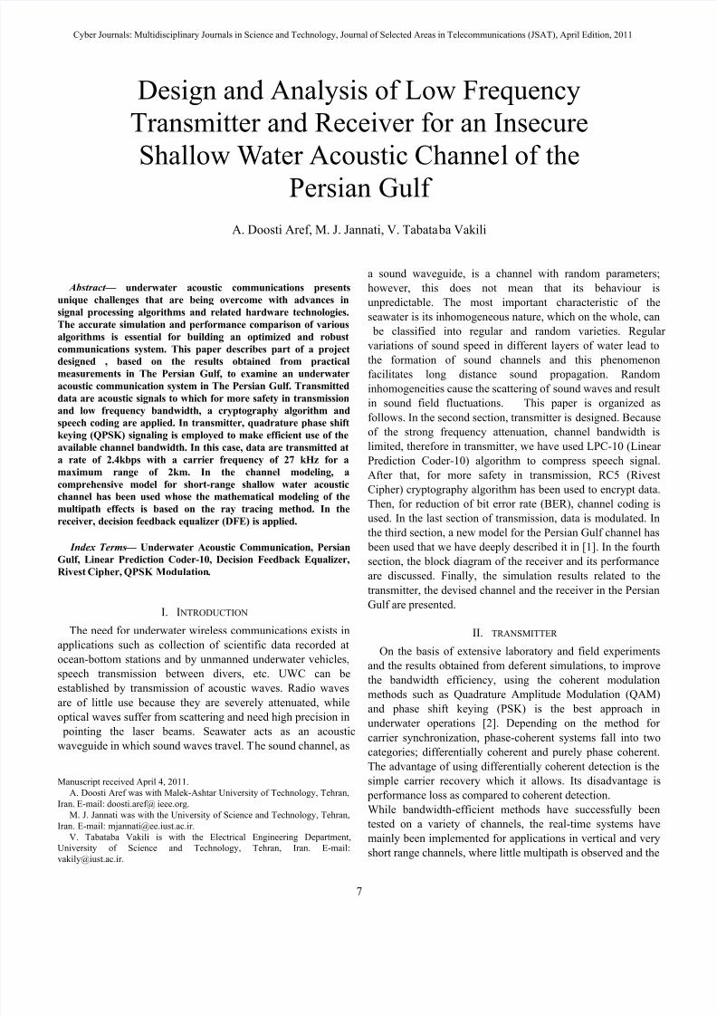
The block diagram of the transmitter is shown in Fig.1. This
transmitter includes blocks for producing the QPSK symbols.The resulting QPSK symbols are then passed through a pulseshaping filter. The rectangular pulses are not practical to sendand require a large bandwidth. Hence, we replace them withshaped pulses that convey the same information but usesmaller bandwidth and have other good properties such asinter symbol interference rejection. In continuation, wecompletely explain each of the blocks.
Fig. 1. Block diagram and structure of the transmitter. phase stability is good [2]. In this paper, for the purpose of compensating for the multipath effects and inter-symbolinterference (ISI), since the considered channel is shallow andhorizontal and the QPSK modulation method in comparisonwith other methods has proper bit error rate, despite low
bandwidth, we have used the QPSK modulation method,which is purely coherent.
The block diagram of the transmitter is shown in Fig.1. Thistransmitter includes blocks for producing the QPSK symbols.The resulting QPSK symbols are then passed through a pulseshaping filter. The rectangular pulses are not practical to send
and require a large bandwidth. Hence, we replace them withshaped pulses that convey the same information but usesmaller bandwidth and have other good properties such asinter symbol interference rejection. In continuation, wecompletely explain each of the blocks.
A. Acoustic Signal Processing In the first block of transmitter, acoustic signal is
compressed with LPC-10 algorithm. Sampling frequency is 8KHz and for any sample, 8 bit is appropriated. Thereforesampling bit rate is 64 kbps. LPC-10 algorithm reduce bit rateto 2.4 kbps, consequently small bandwidth is needed andfrequency attenuation is reduced [3],[ 4].
B. CryptographyIn the second block, data is encrypted with RC5 algorithm.
RC5 is a symmetric block cipher designed to be suitable for both software and hardware implementation.It is a parameterized algorithm, with a variable block size, avariable number of rounds and a variable-length key. This
provides the opportunity for great flexibility in both performance characteristics and the level of security [5]. Inthis paper, block size has been selected 32, number of roundsare 16 and key length is 10.
C. Channel Coding This block is needed for error correction in channel. BCH
(Bose, ray-Chaudhuri, Hocquenghem) coding has beenselected for channel coding. The inputs of applied BCH codeare 12 bits that convert to 32 bits and are transmitted inchannel. This code can correct 5 or fewer random errors inreceiver [6]. In each data transmission, a training sequence towhich allocates 10% of the first transmitted sequences itself ismultiplexed with the data sequences before the QPSK modulation. The main purpose of the training sequence is to
provide the receiver with a known sequence which can be usedfor phase estimation and synchronization in decision feedback equalizer.
D. ModulationThe encoder accepts the sequence of the input binary data. It
has two outputs; in-phase (I), and quadrature (Q). For eachdistinct pair of input binary data a unique combination of I ={±1} and Q ={±1} is assigned. we consider each QPSK symbol as a complex number (I+jQ), whose real and imaginarycomponents are the outputs of the in-phase and quadraturechannels, respectively, to describe those four points separatedin the complex plane by
4
π , 3
4
π , 5
4
π , and 7
4
π . The encoded
data stream of I and Q is then used to modulate a sequence of impulses in which are Transmitted every signaling period; T .To limit their bandwidth such modulated sequences are thenfiltered by LPFs. The same low pass filters are applied at thereceiver. The in-phase and quadrature signals at the output of low pass filter are:
( ) ( ) I i H i
S t I h t iT = −∑ (1)
LPC-10Encoder
IDEA & RC5Encryption
BCHEncoder Encoder
( )i
t iT δ −∑
LPF(Modified Raised-cosine Filter)
LPF(Modified Raised-cosine Filter)
( )ii
I t iT δ −∑
( )ii
Q t iT δ −∑
×
cos2 c f t π cos 2 c f t π
S
U
M
AcousticSignal
cos2 c f t π
( ) x t
I
Q
I
Q
sin2 c f t π cos2 c t π
8/6/2019 Design and Analysis of Low Frequency Transmitter and Receiver for an Insecure Shallow Water Acoustic Channel of …
That ( ) H h t is the impulse response of the low pass filter. The
filtered signals are then multiplied by a carrier frequency,added and transmitted through the Persian Gulf underwater acoustic channel.
To avoid the disadvantages of the side lobes and to reduce
the ISI we transmit data with shaped pulses instead of rectangular pulses. Therefore, the obtained QPSK symbols are passed through a modified raised-cosine filters (LPFs) with aroll-off factor 1 β = and impulse response; ( ) H h t . The
transfer function of the baseband channel has the form:
( ) cos( );2 fT
H f T π =
1 f
T <
(3) ThatT =1/1200s. The transfer function of both the transmitter filter
and receiver filter is then ( ) X f , and the impulse response of the assumed non-fading part of the baseband channel is:
2( ) ( ) j ft x t X f e df π +∞
−∞
=
∫ (4)Thus the impulse response of each filter is obtained throughthe inverse Fourier transform of (2), which is:
1 sin sin( )T h t
T
φ ϕ φ ϕ
= + (5)
Where4
( )2t T
T φ π
+=
4( )
2t T
T ϕ π
−=
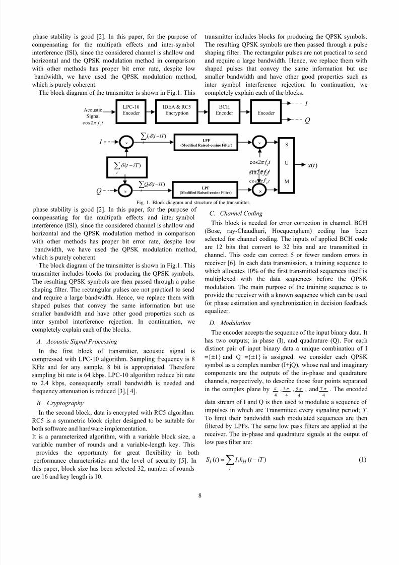
Fig. 2 shows the impulse response of the raised cosine filter.To reduce side lobe levels, the impulse response of the filter ismodified by multiplying it with a Hamming window given as:
( ) 0.76 0.39cos( ) H t w t T π = +
(6)
Fig. 2. Impulse response of the pulse shaping filter The period of Hamming window is 2 T that T is the period of each symbol. This window has 99.96% of its energy in themain lobe, with side lobes of over 20 dB down from the peak [7],[8]. Thus Impulse response of filters is corrected:
( ) ( ). ( ) H T H h t h t w t =
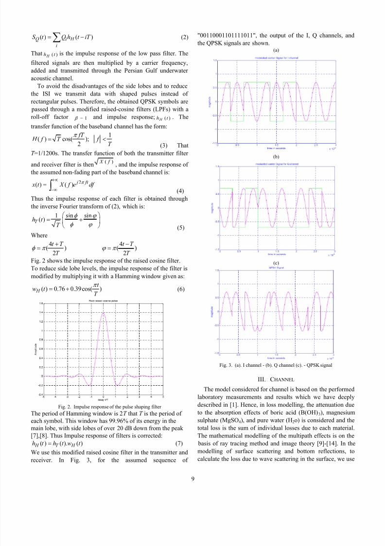
(7)We use this modified raised cosine filter in the transmitter andreceiver. In Fig. 3, for the assumed sequence of
"00110001101111011", the output of the I, Q channels, andthe QPSK signals are shown.
(a)
(b)
(c)
Fig. 3. (a). I channel - (b). Q channel (c). - QPSK signal
III. CHANNEL
The model considered for channel is based on the performedlaboratory measurements and results which we have deeplydescribed in [1]. Hence, in loss modelling, the attenuation dueto the absorption effects of boric acid (B(OH) 3), magnesiumsulphate (MgSO 4), and pure water (H 2o) is considered and thetotal loss is the sum of individual losses due to each material.The mathematical modelling of the multipath effects is on the
basis of ray tracing method and image theory [9]-[14]. In themodelling of surface scattering and bottom reflections, tocalculate the loss due to wave scattering in the surface, we use
8/6/2019 Design and Analysis of Low Frequency Transmitter and Receiver for an Insecure Shallow Water Acoustic Channel of …
the probability density function of the Gaussian Normaldistribution for the surface displacement variable, andlikewise, for the calculation of bottom reflection coefficient,we use the Jackson pattern to select the bottom water typewhich was simulated based on the Strait of Hormuz conditionsand the Hamilton-Bachman model [15]. The model consideredfor noise is the combination of ambient noises such as, thermalnoise, shipping noise, sea state noise, turbulences and the non-Gaussian impulsive noise, due napping shrimps, which is verydominant [16]-[22].
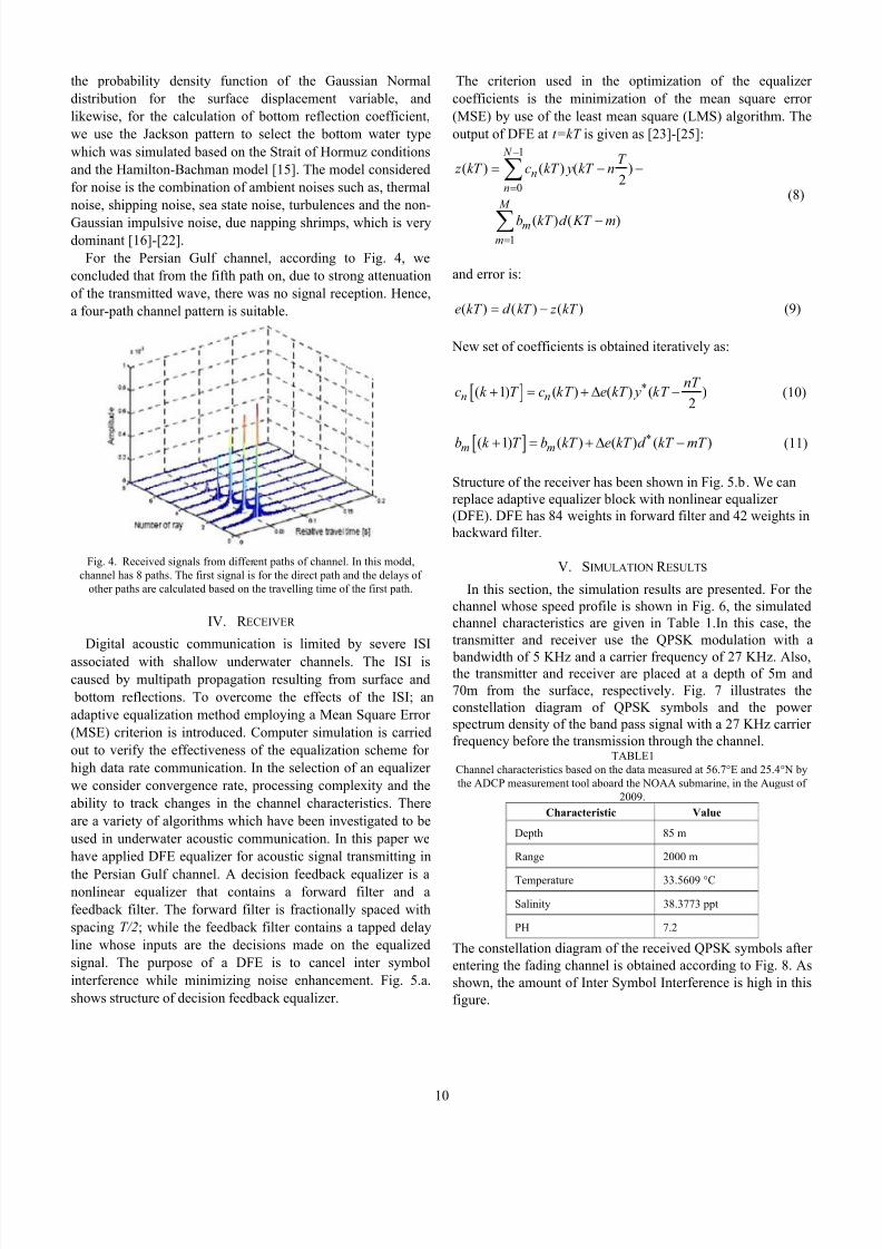
For the Persian Gulf channel, according to Fig. 4, weconcluded that from the fifth path on, due to strong attenuationof the transmitted wave, there was no signal reception. Hence,a four-path channel pattern is suitable.
Fig. 4. Received signals from different paths of channel. In this model,channel has 8 paths. The first signal is for the direct path and the delays of
other paths are calculated based on the travelling time of the first path.
IV. R ECEIVER
Digital acoustic communication is limited by severe ISIassociated with shallow underwater channels. The ISI iscaused by multipath propagation resulting from surface and
bottom reflections. To overcome the effects of the ISI; anadaptive equalization method employing a Mean Square Error (MSE) criterion is introduced. Computer simulation is carriedout to verify the effectiveness of the equalization scheme for high data rate communication. In the selection of an equalizer we consider convergence rate, processing complexity and theability to track changes in the channel characteristics. Thereare a variety of algorithms which have been investigated to beused in underwater acoustic communication. In this paper wehave applied DFE equalizer for acoustic signal transmitting in
the Persian Gulf channel. A decision feedback equalizer is anonlinear equalizer that contains a forward filter and afeedback filter. The forward filter is fractionally spaced withspacing T/2; while the feedback filter contains a tapped delayline whose inputs are the decisions made on the equalizedsignal. The purpose of a DFE is to cancel inter symbolinterference while minimizing noise enhancement. Fig. 5.a.shows structure of decision feedback equalizer.
The criterion used in the optimization of the equalizer coefficients is the minimization of the mean square error (MSE) by use of the least mean square (LMS) algorithm. Theoutput of DFE at t=kT is given as [23]-[25]:
1
0
1
( ) ( ) ( )2
( ) ( )
N
nn
M
mm
T z kT c kT y kT n
b kT d KT m
−
=
=
= − −
−
∑
∑
(8)
and error is:
( ) ( ) ( )e kT d kT z kT = − (9)
New set of coefficients is obtained iteratively as:
[ ]( 1) ( ) ( ) ( )2n n
nT c k T c kT e kT y kT ∗+ = + ∆ −
(10)
[ ]( 1) ( ) ( ) ( )m mb k T b kT e kT d kT mT ∗+ = + ∆ − (11)
Structure of the receiver has been shown in Fig. 5.b. We canreplace adaptive equalizer block with nonlinear equalizer (DFE). DFE has 84 weights in forward filter and 42 weights in
backward filter.
V. SIMULATION R ESULTS
In this section, the simulation results are presented. For thechannel whose speed profile is shown in Fig. 6, the simulatedchannel characteristics are given in Table 1.In this case, thetransmitter and receiver use the QPSK modulation with a
bandwidth of 5 KHz and a carrier frequency of 27 KHz. Also,the transmitter and receiver are placed at a depth of 5m and70m from the surface, respectively. Fig. 7 illustrates theconstellation diagram of QPSK symbols and the power spectrum density of the band pass signal with a 27 KHz carrier frequency before the transmission through the channel.
TABLE1Channel characteristics based on the data measured at 56.7°E and 25.4°N bythe ADCP measurement tool aboard the NOAA submarine, in the August of
2009.Characteristic Value
Depth 85 m
Range 2000 m
Temperature 33.5609 °C
Salinity 38.3773 ppt
PH 7.2
The constellation diagram of the received QPSK symbols after entering the fading channel is obtained according to Fig. 8. Asshown, the amount of Inter Symbol Interference is high in thisfigure.
8/6/2019 Design and Analysis of Low Frequency Transmitter and Receiver for an Insecure Shallow Water Acoustic Channel of …
Fig. 5. (a): Decision Feedback Equalizer. (b): Block diagram and structure of the receiver
Fig. 6. a profile of sound speed variation with depth for the Strait of Hormuz, in 56.7°E (Lon) and 25.4°N (Lat). The water depth was 85m, and the ADCPmeasurement tool, belonging to the NOAA submarine, was placed at a depth of 10 m.
Also, Fig. 9 illustrates the power spectrum density of thetransmitted signal in the channel for each of the special paths.As expected, in the RSRBR path (Fig.9.d), the largestattenuation takes place, and the power level in this pathexperiences a 23dB loss, in comparison with the direct path. Inaddition, the signals received at the channel exit from each of
the 8 paths are shown in Fig. 4. It can be seen that for the fifth path and the remaining paths after it, the signal is stronglyattenuated.
Fig. 10 shows the bit error rates of the received signals atdifferent signal to noise ratio (SNR). In the simulation, thenumber of transmitted bits in each repeat is 5000, and the
T/2
× S
U
M
S
U
M
TrainingSe uence
DecisionDevice
T/2
T/2T
T
T
×
×
×
+
+
×
×
×
C
C
C
C -
1
2
m
t = kT
e (kT)
z (kT)
y (kT)
d (kT)
-
-
CodedData
×
×
LPF
LPF
AdaptiveEqualizer
DecisionDevice
Decoder BCHDecoder
IDEA & RC5Decryption
LPC-10Decoder
( )r t
cos2 c f t π
sin 2 c f t π
( ) I t
( )Q t
( )2 I
kT y
( )2Q
kT y
( ) I kT
( )Q kT
ˆ( ) I kT
ˆ ( )Q kT
DetectedData Coded
Data Acoustic
Signalcos2 c t π
8/6/2019 Design and Analysis of Low Frequency Transmitter and Receiver for an Insecure Shallow Water Acoustic Channel of …
Fig. 7. (a): Constellation diagram of QPSK symbols. (b): power spectrumdensity of band pass signal before entering the channel
Fig. 8. Impulse response of the pulse shaping filter repeat number of training sequence for obtaining the BER in a
specified SNR is 100. Also 2500 symbol is applied for equalizer training. For convergence, the equalizer requiresover 120 iterations.
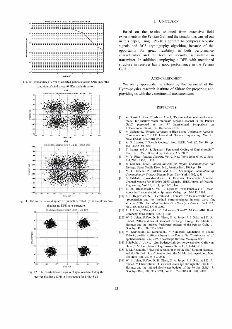
Fig. 11 shows The constellation diagrams of symbolsdetected by the simple receiver which had been used in [1], inthis case we concluded that in applications in which the SNR was more than 6dB, (Fig. 11.a), the implementation of atransmitter and receiver using the QPSK modulation for thementioned channel was appropriate and for lower SNR, e.g.3dB or less, (Fig. 11.b), the use of an equalizer to compensatethe ISI is necessary. On the other hand, Fig. 12 shows theconstellation diagram of symbols detected by the receiver thathas been described in this paper which has a DFE in itsstructure. As a result, the SNR is improved, as well as the
constellation diagram is clearer than Fig. 11.b.(a)
(b)
(c)
(d)
Fig. 9. Power spectrum density of the four special paths used in the
Fig. 10. Probability of error of detected symbols versus SNR under the
condition of wind speed=0.5Kn, and soft bottom (a)
(b)
Fig. 11. The constellation diagram of symbols detected by the simple receiver
that has no DFE in its structure
Fig. 12. The constellation diagram of symbols detected by the
receiver that has a DFE in its structure for SNR=3 dB
I. CONCLUSION
Based on the results obtained from extensive fieldexperiments in the Persian Gulf and the simulations carried outin this paper, using LPC-10 algorithm to compress acousticsignals and RC5 cryptography algorithm, because of theopportunity for great flexibility in both performancecharacteristics and the level of security, is suitable intransmitter. In addition, employing a DFE with mentionedstructure in receiver has a good performance in the PersianGulf.
ACKNOWLEDGMENT
We really appreciate the efforts by the personnel of theHydro-physics research institute of Shiraz for preparing and
providing us with the experimental measurements.
R EFERENCES
[1] A . Doosti Aref and B. Abbasi Arand, “Design and simulation of a newmodel for shallow water multipath acoustic channel in the PersianGulf,” presented at the 5 th International Symposium onTelecommunications, Iran, December 2010.
[2] M. Stojanovic, “Recent Advances in High-Speed Underwater AcousticCommunications,” IEEE Journal of Oceanic Engineering, Vol.121,
No.2, pp.125-136, April 1996.[3] A. S. Spanias, “ Speech Coding,” Proc. IEEE , Vol. 82, No. 10, pp.
1541-1582 Oct. 2001.[4] T. Painter and A. S. Spanias, “Perceptual Coding of Digital Audio,”
Proc. IEEE , Vol. 88, No. 4. pp. 451-515, Apr. 2002.[5] M. Y. Rhee, Internet Security , Vol. 2, New York: John Wiley & Sons
Ltd, 2003, 1950, p. 123.[6] B. Stephen, Error Control Systems for Digital Communication and
Storage , Upper Saddle River, N.J., Prentice Hall, 1995, p. 110.[7] M. C. Jericho, P. Balaban and K. S. Shanmugan, Simulation of
Communication Systems , Plenum Press, New York, 1992, p. 38.[8] A. Falahati, B. Woodward and S. C. Bateman, “Underwater Acoustic
Channel Models For 4800 b/s QPSK Signals,” IEEE Journal of OceanicEngineering , Vol. 16, No. 1, pp. 12-20, Jan.
[9] L. M. Brekhovskikh, Yu. P. Lysanov, “Fundamentals of OceanAcoustics’’, second edition. Springer- Verlag. pp. 130-155, 1999.
[10] K. C. Hegewisch, N. R. Cerruti and S. Tomsovic, “Ocean acoustic wave propagation and ray method correspondence: internal wave finestructure,” The Journal of the Acoustical Society of America , Vol. 117,
No.3, pp. 1582-1594, Oct. 2009.[11] R. J. Urick, ‘’Principles of Underwater Sound’’. McGraw-Hill Book
Company, third edition, 1983, p. 130.[12] W. E. Johns, F.Yao, D. B. Olson, S. A. Josey, J. P Grist, and D. A.
Smeed, “Observations of seasonal exchange through the Straits of Hormuz and the inferred freshwater budgets of the Persian Gulf,” J.Geophys. Res.108 (C12), 2007.
[13] M. Sadrinasab, K. Kenarkoohi, “ Numerical Modelling of soundVelocity profile in different layers in the Persian Gulf ”, Asian journal of applied sciences, 232- 239 , Knowledgia Review, Malaysia 2009.
[14] E.Seibold, J. Ulrich, “ Zur Bodengestalt des nordwestlichen Gulfs vonOman,” .Meteor. Forsch. Ergebnisses, Reihe C, 3, 1–14, 1970.
[15] R. M. Reynolds, “ Physical oceanography of the Gulf, Strait of Hormuz,and the Gulf of Oman” Results from the Mt Mitchell expedition, Mar.Pollution Bull., 27, 35–59, 2006.
[16] W. E. Johns, F.Yao, D. B. Olson, S. A. Josey, J. P Grist, and D. A.Smeed, “ Observations of seasonal exchange through the Straits of Hormuz and the inferred freshwater budgets of the Persian Gulf,” J.Geophys. Res.,108(C12), 3391, doi:10.1029/2003JC001881, 2007.
8/6/2019 Design and Analysis of Low Frequency Transmitter and Receiver for an Insecure Shallow Water Acoustic Channel of …
[17] S. A. Swift, A. S. Bower, “ Formation and circulation of dense water inthe Persian/Arabian Gulf ” J. Geophys. 2003.
[18] M. Sadrinasab, K. ampf, “ Three-dimensional flushing times in thePersian Gulf,” Letters, 31, L201, doi:10.19/204GL025, 2004.
[19] A. Doosti. Aref, “ Survey underwater acoustic communication withdesign and simulation of an Underwater acoustic communication systemin the Persian Gulf,” MSc thesis, Malek-e Ashtar Industrial University,Tehran, Iran, 2010.
[20] H. Medwin, C.S. Clay, “ Fundamentals of Acoustical Oceanography’’,Academic Press, San Diego, pp. 220-228, 1998.
[21]
R.J. Urick, “Ambient Noise in the sea’’, eninsula publishing, P.O.Box867, California. 94023, third edition, pp. 155-205, 1984.[22] K. C. Hegewisch, N. R. Cerruti and S. Tomsovic, “Ocean acoustic wave
propagation and ray method correspondence: internal wave finestructure,” The Journal of the Acoustical Society of America, Vol. 114,Issue 4, p.2428, Oct.2003.
[23] J. P. Gomes and V. Barroso, “SDR Underwater Acoustic Modem,” Ph.DThesis, Instituto de Sistemas e Robotica, Lisboa, Portugal, Apr. 2005.
[24] J. G. Proakis, M. Stojanovic and J. Catipovic, “Phase coherent digitalcommunications for underwater acoustic communications,” IEEEJournal of Oceanic Engineering. Vol. 19, pp. 100-111, Jan. 1994.
[25] A. Masoomzadeh-Fard and S. Pasupathy, “Nonlinear equalization of multipath fading channels with noncoherent demodulation,” IEEE J.Sel. Areas Commun. , vol. 14, no. 3, pp. 512–520, Apr. 1996.
Abdollah Doosti Aref, was born in Tehran, Iran
on 7 Mar, 1983. He received B.Sc. degree inElectrical and Electronic Engineering from theShahed University, Tehran, Iran in 2007 and M.Sc.degree in Communication Systems from the Malek-Ashtar University of Technology, Tehran, Iran in2009. His research interests include digitalcommunications theory and its applications tomobile radio, satellite, radar and especiallyunderwater acoustic communication.Mohammad Javad Jannati, was born in Tehran,Iran on 21 May, 1983. He received B.Sc. degree inElectrical and Electronic Engineering from theShahed University, Tehran, Iran in 2007 and M.Sc.degree in Communication Systems from theUniversity of Science and Technology, Tehran, Iranin 2010. His research interests include Speech
processing, underwater acoustic communication,cooperative communication and MIMO-OFDM systems.Professor Vahid Tabataba Vakili, was born inTehran, Iran. He received B.Sc. degree in Electricaland Electronic Engineering from the sharif university of Tehran , Tehran, Iran . He receivedM.Sc. and PHD degrees in CommunicationSystems from the university Bradford , Bradford,England .Prof. Vakili is a faculty member of Iran university
of science and technology. His research interests include digitalcommunications theory, satellite communication, Signal processing, mobileand cooperative communication and MIMO-OFDM systems.