Page 1
Wright State University Wright State University
CORE Scholar CORE Scholar
Browse all Theses and Dissertations Theses and Dissertations
2016
Design and Application of Facile Routes to N-Heterocycle Design and Application of Facile Routes to N-Heterocycle
Functionalized Poly(arylene ether)s Functionalized Poly(arylene ether)s
Abraham K. Kemboi Wright State University
Follow this and additional works at: https://corescholar.libraries.wright.edu/etd_all
Part of the Chemistry Commons
Repository Citation Repository Citation Kemboi, Abraham K., "Design and Application of Facile Routes to N-Heterocycle Functionalized Poly(arylene ether)s" (2016). Browse all Theses and Dissertations. 2042. https://corescholar.libraries.wright.edu/etd_all/2042
This Thesis is brought to you for free and open access by the Theses and Dissertations at CORE Scholar. It has been accepted for inclusion in Browse all Theses and Dissertations by an authorized administrator of CORE Scholar. For more information, please contact [email protected] .
Page 2
DESIGN AND APPLICATION OF FACILE ROUTES TO N-HETEROCYCLE
FUNCTIONALIZED POLY(ARYLENE ETHER)S
A thesis submitted in partial fulfillment
of the requirements for the degree of
Master of Science
By:
ABRAHAM K. KEMBOI
BEDS, Moi University, 2008
2015
Wright State University
Page 3
WRIGHT STATE UNIVERSITY
GRADUATE SCHOOL
July 30, 2015
I HEREBY RECOMMEND THAT THE THESIS PREPARED UNDER MY SUPERVISION BY
Abraham K. Kemboi ENTITLED Design and Application of Facile Routes to N-Heterocycle
Functionalized Poly(arylene ether)s BE ACCEPTED IN PARTIAL FULFILLMENT OF THE
REQUIREMENTS FOR THE DEGREE OF Master of Science.
_______________________________
Eric Fossum, Ph.D.
Thesis Advisor
_______________________________
David Grossie, Ph.D.
Chair, Department of Chemistry
Committee on
Final Examination
_______________________________
Eric Fossum, Ph.D.
_______________________________
Daniel M. Ketcha, Ph.D.
_______________________________
William A. Feld, Ph.D.
_______________________________
Robert E. W. Fyffe, Ph.D.
Vice President for Research and
Dean of the Graduate School
Page 4
iii
ABSTRACT
Abraham Kemboi M.S., Department of Chemistry, Wright State University, 2015. Design and
Application of Facile Routes to N-Heterocycle Functionalized Poly(arylene ether)s
A series of 3,5-difluorinated systems, which are activated towards nucleophilic aromatic
substitution (NAS) by the strongly electron withdrawing benzoxazole or benzothiazole groups,
located meta to the fluorines were prepared and fully characterized. The monomers also carry
various N-heterocyclic species on the non-fluorinated ring. The corresponding poly(arylene
ether)s, some of which were copolymers with triphenylphosphine oxide-based monomers, were
prepared via standard NAS polycondensation reactions. Incorporation of the monomers containing
N-heterocycle units was determined by NMR spectroscopy. Characterization of the thermal
properties was done using thermogravimetric analysis (TGA) and differential scanning (DSC).
Most of the polymers displayed good film forming properties when cast from NMP solutions. The
thermal properties of the polymers were very impressive with glass transition temperatures above
200 ⁰C and 5 % weight loss temperatures of over 470 ⁰C under a nitrogen atmosphere.
Page 5
iv
TABLE OF CONTENTS
1. INTRODUCTION
1.1 Organic light emitting diode…………………………………………………....…….……….1
1.2 Device structure and fabrication……………………………………………...……………….2
1.3 Fluorescent organic materials for OLED………………………………….…….……….…....4
1.3.1 Small Molecules……………………………………...……………...…….……….4
1.3.2 Conjugated polymers…………………………………………………….…………5
1.4 Band Gap Energy and Color………………………………..…………….……..……….6
1.5 Solvent Effects on UV and Fluorescence Spectra…….……………..……….………….8
1.6 Poly (arylene ether)s, PAEs……………………………………………..…….…………9
1.6.1 Poly(arylene ether phosphine oxide), PAEPO……………………..……..………..9
1.6.2 Polymerization via Nucleophilic Aromatic Substation (NAS)……..……....…….10
1.6.3 Pre and Post modification of polymers…………………………..……………….11
1.6.4 Poly(arylene ether-benzoxazole), PAEBO and poly(arylene ether-benzothiazole)
(PAEBT)…………………………………….……………………………..…….12
1.6.5 Poly(arylene ether)s with pendent benzoxazole or benzothiazole…...……..…….14
1.7 Current project………………………..……….……………..…….…….……………..16
Page 6
v
2. EXPERIMENTAL
2.1. Instrumentation ………………………………………..…………………………………17
2.2 Materials………………………………………………………….……………………….17
2.3 Synthesis of BOX-Br ………...……………………………………………….….…….…18
2.4 Synthesis of BOX-CBZ……………………………………..…………….………………19
2.5 Synthesis of BOX-IND……………………………………..…………….………………20
2.6 Iodination BTZ ……………………………………………………………..…………….21
2.7 Synthesis of BTZ-CBZ monomer……………………………………………………..….22
2.8 Representative synthesis of BOX-CBZ copolymers (10a-10d)…………………………..23
2.9 Synthesis of BTZ-CBZ copolymer………………………………………….……….…....23
2.10 Synthesis of BOX-IND copolymer…………………..……………………….………....24
2.11 Characterization
2.11.1 Nuclear Magnetic Resonance (NMR) Analysis…………………………………..25
2.11.2 Thermogravimetric Analysis (TGA) ……………………………..………………25
2.11.3 Differential Scanning Calorimetry (DSC)………………………………………..25
2.11.4 Absorption and Emission Spectra …......................................................................26
Page 7
vi
3. RESULTS AND DISCUSSION
3.1 Synthesis of BOX-BR.………………………………………...…………..……………..27
3.2 Synthesis of BOX-CBZ …..……………………………………………………………..30
3.3 Synthesis of BOX-IND …...……………………………………………………….…….33
3.4 Iodination of BTZ……………………………………………………………………......35
3.5 Synthesis of BTZ-CBZ ....………………………………………..…….…………….….37
3.6 UV and Fluorescence of monomers BOX-CBZ, BOX-IND, BTZ-CBZ…………...…....40
3.7 Synthesis of copolymers 10a-10d, 11 and 12……………...…………………….………42
4 Thermal Analysis………………………………………………………………………….47
5 Absorption and Emission ………………………………..……………………………..... 50
4. CONCLUSION………………………………………………………………………………54
5. FUTURE WORK. …………………………………………………………………………...56
6. REFERENCES………………………………………………………….………….…..…….57
Page 8
vii
LIST OF FIGURES
Figure 1. Typical OLED Device Structures……………………………………………...………3
Figure 2. Structures of small fluorescent molecules…………………………………………......4
Figure 3. Examples of conjugated fluorescent polymers………………………………..……….5
Figure 4. Illustration of HOMO-LUMO energy gap and color…………………………………..6
Figure 5. Fluorescent molecules containing Donor-Acceptor groups…………….……………...7
Figure 6. Monomers synthesized in the current work………………………………...…………16
Figure 7. 300 MHz 1H (CDCl3) NMR spectrum of BOX-BR …. ………………………………28
Figure 8. 75.5 MHZ 13C NMR (CDCl3) spectrum of BOX-BR. ……………………………......29
Figure 9. 300 MHZ 1H NMR (CDCl3) spectrum BOX-CBZ ……………………..…….………31
Figure 10. 75.5 MHZ 13C NMR (CDCl3) spectrum BOX-CBZ ….………...………..………….32
Figure 11. 300 MHZ 1H NMR (CDCl3) spectrum of BOX-IND monomer. ….. ……….………34
Figure 12. 75.5 MHZ 13C NMR (CDCl3) spectrum of BOX-IND monomer …. ………….……35
Figure 13. 300 MHZ 1H NMR (CDCl3) spectrum of BTZ-I … ……………………….………..37
Figure 14. 300 MHz 1H NMR (CDCl3) spectrum BTZ-CBZ………………….……………… 38
Figure 15. 75.5 MHz 13C NMR (CDCl3) spectrum of BTZ-CBZ ……………………..……….39
Figure 16. (a) Absorption and (b) Fluorescence spectra of BTZ-CBZ, BOX-CBZ and BOX-IND
in THF, excited at 310 nm………………………………………………………………………40
Figure 17. An overlay of BTZ-CBZ fluorescence spectra in THF and NMP, excited at 300nm.41
Page 9
viii
Figure 18. 13C NMR spectrum 10a and 10c ………………………….…………………………43
Figure 19. 13C NMR spectrum 12 ……………………………………………………………....45
Figure 20. 13C NMR spectrum of 11 …………………………………………………………....46
Figure 21. Overlay of TGA traces of the polymers 10a-10d, 11, and 12…………………….....47
Figure 22. DSC traces of the polymers 10a-10d, 11 and 12 under nitrogen………………….. 49
Figure 23. (a) Absorption and (b) Emission spectrums of BOX-CBZ copolymers excited at
310nm…………………………………………………………………………..……………….50
Figure 24. (a) Fluorescence of 10a -10d, 11 and 12 in NMP. (b) Fluorescence of monomer 9 and
polymer 11 excited at 310 nm……………..…………………………………………………….51
Figure 25. Fluorescence of polymer films containing 15% chromophores, excited at 310
nm………………………………..………………………………………………………………52
Figure 26. Fluorescence of BTZ-CBZ copolymer under UV lamp..…………...………………53
Page 10
ix
LIST OF SCHEMES
Scheme 1. Synthesis of poly(arylene ether phosphine oxide)…………………..……………….10
Scheme 2. Mechanism of Nucleophilic Aromatic Substitution reaction (NAS)…………..……11
Scheme 3. Routes for the introduction of functional groups to polymers…………………….…12
Scheme 4a. Poly(arylene ether-benzoxazole)s (PAEBO)……………………………....……….13
Scheme 4b Synthesis of poly(arylene ether benzothiazole)s (PAEBT)…………………..….….13
Scheme 5. Synthesis of poly(arylene ether)s with pendent benzoxazole or benzothiazole from
from 2,6-difluorinated system ……………..…………….……………………….……….……..14
Scheme 6. Synthesis of poly(arylene ether)s with pendent benzoxazole or benzothiazole from
3,5-difluorinated system ……………...…………………….…………………………………...15
Scheme 7. Synthesis of BOX-Br. ….……………………………………………………………27
Scheme 8. Synthesis of BOX-CBZ monomer ………………………………………………......30
Scheme 9. Synthesis of BOX-IND monomer. ………....………………………………………..33
Scheme 10. Synthesis of BTZ-I ….……………………………………………………………...36
Scheme 11. Synthesis of BTZ-CBZ monomer ….………………………………………………38
Scheme 12. Synthesis of polymers 10a-10d, 11, and 12…………...……………………………42
Page 11
x
LIST OF TABLES
Table 1. Glass transition (Tg) and 5% degradation temperatures for polymers 10a-10d, 11, and
12. ………………………………………………………..……………………………………..48
Page 12
xi
ACKNOWLEDGEMENTS
I would like to express my sincere gratitude to my research advisor, Dr. Eric Fossum for
his guidance, patience, and inspiration throughout the program. I have exceedingly benefited
from his vast knowledge, encouragement, and exceptional personality. Thank you to my
committee members, Dr. William Feld and Dr. Daniel Ketcha. I would also like to thank Dr.
Fossum’s research group, as well as the faculty and staff members of the Wright State University
Department of Chemistry.
I would also like to acknowledge Dr. David Dolson and Dr. Pavel’s research groups for
their advice and guidance in UV and Fluorescence measurements. Thanks to Dr. Ioana Pavel for
allowing us to use their analytical instruments for measurements.
My loving wife, Lenah, deserve a lot of recognition for encouragement and
understanding throughout the program. Words cannot express my gratitude for your
determination and hard work in bringing up our son, Ethan.
This work was supported by a grant from the National Science Foundation, CHE-
1307117.
Page 13
xii
DEDICATION
Dedicated to my loving wife, Lenah and my son, Ethan
for
their love, support, and encouragement
Page 14
1
1. INTRODUCTION
1.1 Organic light emitting diode
Over the past few years, the lighting and display industry has seen rapid growth and
development in technology due to the discovery of new and advanced materials that are highly
efficient and easy to fabricate into lighting devices. Among the leading devices currently in the
market are the light emitting diodes (LED). LED is a semiconductor device that emits
visible light when an electric current passes through it. There are two types of LEDs, the Inorganic
Light Emitting Diode (ILED), which utilize some metals to emit light, and the Organic Light
Emitting Diodes (OLED) which utilize organic materials to emit light. ILED was first developed
in the early 1960s, and have achieved a great success in performance and fluorescence lifetime.
The cost of ILED is still high due to processing difficulties and high cost of rare elements used as
emitters. Despite the challenges, ILEDs have been used extensively in lighting and displays and
have shown better efficiencies compared to incandescent bulbs and fluorescent tubes.
The OLED technology has attracted much attention among scientists due to ease of
fabrication of OLED devices, and the possibility of design and synthesis of molecules with
different optoelectronic properties. This, together with the high demand for advanced materials
for lighting and display devices, has led to numerous research in OLED and rapid growth in the
industry. Due to their superior performance, organic emitting materials are currently considered as
the next-generation lighting and display technology for many applications and a good alternative
to the more expensive ILED. The OLED technology now plays a significant role in flat-panel
displays, solid-state lighting, and organic solar cells.
Page 15
2
Early OLED devices utilized high voltage, mainly AC current, which was applied to thin
films of the organic material.1 In the 1960’s, Pope and his team developed a DC driven OLED
device with a single crystal of anthracene as the emitter. 1, 2 The device required a voltage too high
for ease of operation (›300v) and was not reliable enough to further exploit for commercial
purposes. 1, 2 Scientists were unable to lower the device driving voltage until the 1980s when the
voltage was noticeably reduced, but the efficiency was still too low to exploit for commercial
purposes. 1, 2
The Kodak Company made a big contribution to OLED development by introducing a
device structure, consisting of indium tin oxide (ITO)/diamine/AlQ3/MgAg, which is almost the
same as the ones used today. 1 The layers in the device served different purposes, the ITO, which
is a transparent conductor, served as the anode layer, the diamine was utilized as the hole
transporting layer, AlQ3 an emitter and electron transporting material, and MgAg as the cathode.
2 In 1990, a team of British scientists developed an electroluminescent device, using poly (p-
phenylene vinylene). 1, 2 This material simultaneously worked as an electric charge bipolar carrier
and emitter. The use of PPV in OLED was the beginnings of polymer light emitting diodes (PLED).
1, 2
1.2 Device structure and fabrication
Early studies on device structure and fabrication focused on devices based on single crystal
emitters. Numerous reports on device efficiency and lifetime have been published which shows
that OLEDs based on single crystals are not useful for practical applications, the high voltages,
small light-emitting areas, and difficulty of single crystal processing limits their application. 2 an
Page 16
3
alternative to the single crystal devices is thin film devices, they are easy to fabricate and are more
efficient for practical and commercial application.
Multilayer device structures consist of layers of organic material, which help to improve
device efficiency and lifetime. Many structures consist of a transparent indium tin oxide (ITO)
anode, an organic hole transporting layer (HTL), organic electron transporting layer (ETL) and a
metal cathode usually aluminum or Al:Mg alloy. Bilayer devices can be fabricated as follow;
ITO/HTL/ETL (EML)/METAL or ITO/HTL(EML)/ETL/METAL. The HTL helps with injection
of holes from the anode (ITO) into the organic material. ETL injects electrons from the metal
cathode. A thin EML can also be sandwiched between the HTL and ETL to form a three-layered
structure. 2
Modern devices make use of buffer layers to improve efficiency by lowering the drive
voltage and preventing chemical interactions between the layers, which lower the performance
and lifetime of the diode. 2 The figure below shows the three typical OLED device structures.
From left to right; Double layered structure with an ETL emitter, double layered with an HTL
emitter, and a triple layered device structure.
Figure 1. Typical OLED Device Structures.
Page 17
4
1.3 Fluorescent organic materials for OLED
1.3.1 Small Molecules
Small molecule OLED technology was pioneered by the Eastman Kodak Company. The
technology utilized low molecular weight fluorescent molecules for light emission. Fabrication of
a thin layer device is usually done by vacuum or wet deposition which lead to high costs of
production and hence limit its use to small-area devices. 2,3 The advantage of the vacuum
deposition process is that it enables the formation of uniform films and easy development of very
complex structures, which are often more efficient.2,3 The structures of some small conjugated
molecules for OLED applications are shown in Figure 2.
N
O
AL
3
AlQ3 -Green
N N
2,7-Bis(carbazol-9-yl)-9,9-spirobifluorene -Sky blue
Figure 2. Structures of small fluorescent molecules.
Figure 2 shows two examples of small molecules used for OLED. Tris(8-
hydroxyquinolinato)aluminum (AlQ3) is a complex in which aluminum is bonded to three 8-
hydroxyquinoline ligands. It is one of the earliest and widely investigated fluorescent molecule
with good electron transporting properties and green emission. AlQ3 can be tuned to emit the full
light spectrum (RGB) by attaching different electron donating or withdrawing groups to the five
Page 18
5
position of the quinolate ligand. 1 2,7-bis(carbazoyl-9-yl)-9,9-spirobifluorene is a blue emitting
small molecule.
1.3.2 Conjugated polymers
Conjugated polymers are high molecular weight organic compounds that contain a long
chain of alternating single and double bonds. The sp2-hybridized carbon atoms are bonded to three
other atoms, via sigma bonds, leading to one unpaired electron per carbon atom in a pz orbital.
The carbon atoms along the polymer chain possess the same hybridization which results in a
delocalized pi system, this allows charge transfer along the polymer chain. The conjugation allows
the polymer to exhibit semiconducting properties. 1, 4, 5 The structures of some conducting
polymers are shown in Figure 3.
Figure 3. Examples of conjugated fluorescent polymers.
Poly(p-phenylene vinylene), PPV, is the first polymer electroluminescent material to be
used for OLED applications. It emits with bright yellow-green color and can be tuned to emit
different colors by attaching different organic groups to the polymer backbone. However, due to
its poor resistance to light and oxygen degradation, PPV is not widely used for OLED applications.
Page 19
6
1 2 Polyfluorene (PF) has attracted considerable attention in the OLED technology due to its high
photoluminescence efficiency, high stability, and ability to emit at different wavelengths with
some structural modification.
1.4 Band Gap Energy and Color
Fluorescent organic molecules contain orbitals that allow movement of electrons from the
ground state to the excited state and vice versa. The energy gap (Eg) between the highest occupied
molecular orbital (HOMO) and the lowest unoccupied molecular orbital (LUMO) determines the
wavelength and fluorescence of organic molecules. Figure 4 illustrates the relationship between
Eg and fluorescence color.
Figure 4. Illustration of HOMO-LUMO energy gap and color
Large Eg values lead to shorter absorption and emission wavelengths, a ‘blue shift’ and a
higher excitation energy, while small Eg lead to longer absorption and emission wavelengths and
a ‘red shift’. The energy gap in organic molecules can be tuned to obtain different optoelectronic
Page 20
7
properties.6,7,8 For example, the energy gap in PPV can be increased, by reducing the planarization
and conjugation between the phenyl and vinyl groups, leading to a blue-shift.1, 7
Molecules containing an electron-donating group (D) linked to an electron accepting group (A) by
-bonds, D--A, can be tuned to emit different colors by the appropriate choice of donor or
acceptor group. A red shift in emission wavelength of D--A fluorescent molecules is attributed
to the greater charge transfer character caused by higher electron-donating strength or greater
electron withdrawing ability and vice versa. 9 The choice of donor and acceptor groups could help
to reduce the band gap energy for red emission or increase the band gap energy for blue emission.1,
3, 10 Figure 5 shows an example of a fluorescent molecule containing D-π-A. The 2,7-divinyl-9,9-
bis(tert-butyl)fluorene (π) forms a π-bridge that connect the electron donor, diphenylamine (D) to
an electron acceptor, diphenyloxadiazole (A), to form a D-π-A system. The molecule has strong
fluorescence at ~ 460 nm and exhibits good charge transfer properties. 11
Figure 5. Fluorescent molecule containing Donor-Acceptor groups.
Page 21
8
1.5. Solvent Effects on UV and Fluorescence Spectra
The florescence wavelength, intensity, and shape of absorption and emission spectra of
organic molecules are usually susceptible to the environment surrounding the fluorescing
molecules. 12 Fluorescent molecules in different solvents show spectral shifts which are attributed
to interactions between solute and solvent molecules. These interactions can be in the form of
hydrogen bonding, acid-base chemistry or bulk solvent effects. 12 The magnitude of the spectral
shifts in different solvents depends on the strength of the intermolecular hydrogen bonds between
the substituent groups of the chromophore molecule and – OH or – NH groups of the surrounding
solvent molecules. 12 Molecules with intramolecular hydrogen system are less affected by solvent
polarity due to stronger intermolecular attraction, while systems without intramolecular hydrogen
bond are highly affected.
Molecules with π-π* transitions are shifted to longer wavelength when solvent polarity
increases. 12 The excited state of a molecule has an increased dipole moment compared to the
ground state hence the fluorescence band maxima of excited states are red-shifted significantly
more when the solvent polarity increases compared to the absorption band under the same
conditions. Conjugated polymers also show unique fluorescence in the solid state, more ordered
polymers have redder spectra and lower quantum yield due to strong interactions between
molecules which lead to loss of energy in the excited states or quenching, while polymer chains in
poorly packed regions behave nearly as if in solution, having bluer spectra, high quantum yields,
and exponential decay.4, 12,
Page 22
9
1.6 Poly (arylene ether)s, PAEs
Poly(arylene ether)s, PAE, are engineering thermoplastics whose structures consist of
aromatic rings linked by ether bonds. They have excellent thermal stability and mechanical
properties due to the presence of rigid, electron rich aromatic groups in their backbone. They are
commonly used in many industrial applications due to their excellent resistance towards hydrolysis
and oxidation. Some PAEs discussed in this work include poly(phenylene oxide), PPO,
poly(arylene ether benzoxazole and benzothiazole), poly(arylene ethers) with pendent
benzoxazole or benzothiazole units, and poly(arylene ether phosphine oxide), PAEPO.
1.6.1 Poly(arylene ether phosphine oxide), PAEPO
PAEPOs are high performance engineering thermoplastic materials with excellent
hydrolytic, thermal and oxidative stability, possessing a glass transition temperature, Tg, range
from 190 ⁰C – 280 ⁰C. They are more self-extinguishing than any other engineering thermoplastics
tested when burning, due to the presence of phosphorus.13, 14 They have high resistance to
aggressive oxygen plasma environments, which is achieved by forming a highly oxidized, non-
volatile phosphorus-containing surface layer. They are synthesized via nucleophilic aromatic
substitution polymerization of bisphenols with phosphorus containing activated dihalides (Scheme
1). The reaction is accomplished in the presence of a weak base, potassium carbonate, and a polar
aprotic (NMP) at temperature around 175 ⁰C. PAEPOs have excellent thermal stability, losing 5%
of their weight typically at about 500 ⁰C and a high degree of char at 600 ⁰C-800 ⁰C. 14 As
compared to other commercially available engineering thermoplastics like poly(ether ether
Page 23
10
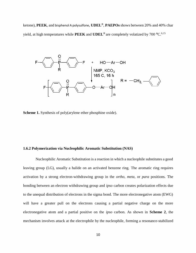
ketone), PEEK, and bisphenol A polysulfone, UDEL®, PAEPOs shows between 20% and 40% char
yield, at high temperatures while PEEK and UDEL® are completely volatized by 700 ⁰C.6,15
Scheme 1. Synthesis of poly(arylene ether phosphine oxide).
1.6.2 Polymerization via Nucleophilic Aromatic Substitution (NAS)
Nucleophilic Aromatic Substitution is a reaction in which a nucleophile substitutes a good
leaving group (LG), usually a halide on an activated benzene ring. The aromatic ring requires
activation by a strong electron-withdrawing group in the ortho, meta, or para positions. The
bonding between an electron withdrawing group and ipso carbon creates polarization effects due
to the unequal distribution of electrons in the sigma bond. The more electronegative atom (EWG)
will have a greater pull on the electrons causing a partial negative charge on the more
electronegative atom and a partial positive on the ipso carbon. As shown in Scheme 2, the
mechanism involves attack at the electrophile by the nucleophile, forming a resonance-stabilized
Page 24
11
anion known as a Meisenheimer complex. This step is slow and hence the rate determining step.
The second step occurs when the negative charge on the ring pushes out the leaving group to
rearomatize the ring. The second step is fast since the aromaticity of the ring is restored. Electron
Donating Groups (EDG) on the other hand deactivate the ring by destabilizing the intermediate
formed in the first step of reaction. 17
Scheme 2. Mechanism of Nucleophilic Aromatic Substitution reaction (NAS).
1.6.3 “Pre” and “Post” Modification
Functional groups can be introduced into polymers to obtain desired physical and chemical
properties (Scheme 3). This can be done in two ways. First is pre-functionalization in which the
monomer units are modified before polymerizing. The monomers are then polymerized to give a
functionalized polymer. Functionalized monomers can also be copolymerized with unmodified
monomers to form copolymers with desired properties. The second method involves introducing
functional groups at the polymer stage, also known as post modification. Pre-functionalization
requires that the functional groups introduced into the monomer remain unaffected by the
Page 25
12
polymerization conditions. The post modification on the other hand is limited by the difficulty in
controlling the location of functional groups.
Scheme 3. Routes for the introduction of functional groups to polymers.
1.6.4 Poly(arylene ether-benzoxazole), PAEBO and poly(arylene ether-benzothiazole)
(PAEBT)
Poly(arylene ether-benzoxazole), PAEBO, can be prepared by nucleophilic aromatic
substitution (Schemes 4a). Fluorine atoms in the para-substituted bisbenzoxazoles are activated
towards NAS and are readily displaced by phenoxides. Different bisphenols can be used to
synthesize the polymers in the presence of NMP solvent and K2CO3. The polymerization process
is accomplished by formation of aryl-ether bonds. The polymers can be processed from solutions
or melt due to their thermal stability. PAEBOs show high Tg values, ranging from 213 ⁰C to 300
Page 26
13
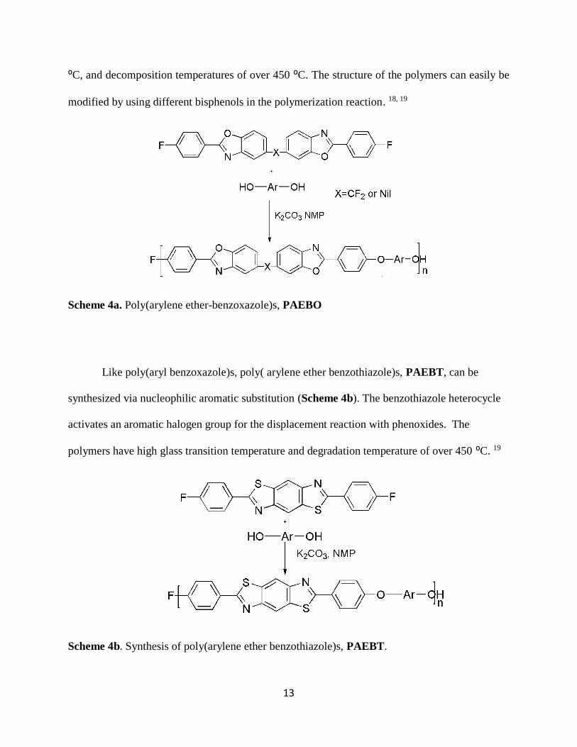
⁰C, and decomposition temperatures of over 450 ⁰C. The structure of the polymers can easily be
modified by using different bisphenols in the polymerization reaction. 18, 19
Scheme 4a. Poly(arylene ether-benzoxazole)s, PAEBO
Like poly(aryl benzoxazole)s, poly( arylene ether benzothiazole)s, PAEBT, can be
synthesized via nucleophilic aromatic substitution (Scheme 4b). The benzothiazole heterocycle
activates an aromatic halogen group for the displacement reaction with phenoxides. The
polymers have high glass transition temperature and degradation temperature of over 450 ⁰C. 19
Scheme 4b. Synthesis of poly(arylene ether benzothiazole)s, PAEBT.
Page 27
14
1.6.5 Poly(arylene ether)s with pendent benzoxazole or benzothiazole (PAE-pBO and PAE-
pBT)
Like PAEPO, PAE-pBO and PAE-pBT are high performance engineering
thermoplastics. They have high glass transition temperatures, high thermal stability, and good
mechanical properties. Synthesis of PAE-pBO and PAE-pBT is done via typical nucleophilic
aromatic substitution of dihalogenated aromatic group which are activated towards NAS by a
strong electron withdrawing group with bisphenols. The reaction occurs at 185 ⁰C in a polar aprotic
solvent. Monomers containing 2,6 difluorinated systems, 2-(2,6-difluoropheny1)benzoxazole, and
2-(2,6-difluorophenyl)-benzothiazole, were synthesized by J. Hedrick and coworkers. They
successfully copolymerized with bisphenol-A, yielding high molecular weight polymers with
pendent benzoxazole or benzothiazole Scheme 5. 20 PAE-pBO and PAE-pBT have also been
synthesized using 3,5 difluorinated systems to form high molecular weight polymers with
impressive properties, Scheme 6. 17, 20
Scheme 5. Synthesis of poly(arylene ether)s with pendent benzoxazole or benzothiazole groups
from 2,6-difluorinated system.
Page 28
15
Scheme 6. Synthesis of poly(arylene ether)s with pendent benzoxazole or benzothiazole groups
from 3,5 difluorinated system.
Page 29
16
1.7 Current project
The current project seeks to design and synthesize PAE-based fluorescent polymers, in
which the backbone is not a conjugated polymer, for blue organic light emitting diodes (OLED).
Two difluorinated monomers, which are activated toward NAS reactions by either a benzothiazole
or benzoxazole group located in the meta-positions (Figure 6), are prepared for use in the
polymerization reaction. The goal is to utilize the benzoxazole and benzothiazole as acceptor
groups for donor/acceptor chromophores. Donor groups, which are electron rich aromatic amines,
are attached to the acceptor to form a ‘Push-Pull’ system, which allows charge transfer between
the donor and acceptor. The properties of PAEs, which include high resistance to hydrolysis,
thermal stability, and strong resistance to oxidation, can allow for better device performance in
extreme conditions of heat and air.
Figure 6. Monomers containing electron donating group, EDG, and electron withdrawing group,
EWG, used in polymer synthesis.
Page 30
17
2. EXPERIMENTAL
2.1 Instrumentation
A Bruker AVANCE 300 MHz instrument was used to acquire 1H and 13C Nuclear
Magnetic Resonance (NMR) spectra. The instrument operates at 300 and 75.5 MHz, for 1H and
13C, respectively. Monomer samples were dissolved in an appropriate deuterated solvent (DMSO-
d6 or CDCl3) at a concentration of ~ 35mg / 0.7 mL, while polymer samples were dissolved in a
NMP-DMSO-d6 mixture (40 mg / 0.2:0.5 mL). A Hewlett-Packard (HP) 6890 Series GC, coupled
with a HP 5973 Mass Selective Detector/Quadrupole system, was used to perform GC/MS
analyses. Differential Scanning Calorimetry (DSC) and Thermogravimetric analyses (TGA) were
carried out on TA Instruments DSC Q200 (under nitrogen) and TGA Q500 (under nitrogen or air),
respectively, at a heating rate of 10 ºC/ min. Melting points were determined on a MEL-TEMP
instrument and elemental analyses were obtained from Midwest Micro Labs Inc., Indianapolis, IN.
Fluorescence data was acquired using an Agilent Technologies Cary Eclipse fluorescence
Spectrophotometer, while UV/Vis data was acquired using an Agilent Cary 60 UV-VIS
Spectrometer.
2.2 Materials
The compounds 2-Amino-4-bromophenol and 3,5-difluorobenzoic acid were purchased
from Oakwood Chemicals and used as received. N-Iodosuccinimide was purchased from Oakwood
Chemicals and used as received. 2-Aminothiophenol and N,N-dimethylglycine were purchased
from Sigma Aldrich and used as received. Carbazole was purchased from Sigma Aldrich and
recrystallized from chloroform before use. Indole was purchased from Lancaster Labs and used as
Page 31
18
received. 4,4’-Biphenol was purchased from TCI and recrystallized from hexanes with a few drops
of ethanol. Bis-(4-fluorophenyl)phenylphosphine oxide was received from Daychem Laboratories.
Copper (I) iodide was purchased form Sigma Aldrich and activated by washing in a Soxhlet
extractor with hot THF. Potassium carbonate was purchased from Sigma Aldrich and dried at 130
°C in oven. Calcium carbonate was purchased from Allied Chemicals and dried in oven at 130 °C
before use. Sodium bicarbonate was purchased from Fisher Chemicals. NMR solvents,
Chloroform-d (CDCl3) and dimethyl sulfoxide-d6 (DMSO-d6) were purchased from Sigma
Aldrich. N-Methylpyrrolidinone (NMP) was purchased from Sigma Aldrich dried over CaH2 and
distilled under nitrogen prior to use. 2-(3,5-difluorophenyl)-benzothiazole (BTZ) was synthesized
via a previously reported route. Tetrahydrofuran (THF) was received from Macron. Dimethyl
sulfoxide (DMSO) was received from Sigma Aldrich, dried over CaH2 and distilled under nitrogen
before use. Chloroform (CHCl3) and sulfuric acid (H2SO4) were purchased from BDH. Toluene
was purchased from EMA and used as received. Ethanol was received from Decon Labs Inc. Non-
iodized Morton salt was purchased from a local Meijer store and used as received.
2.3 Synthesis of BOX-Br, 3
In a 250 mL round-bottomed (RB) flask, equipped with a stir bar and condenser, were
placed 2-amino-4-bromophenol (5.0 g, 26 mmol), 3,5-difluorobenzoic acid (5.5 g, 32 mmol) and
50 g of polyphosphoric acid (PPA). The mixture was immersed in a silicone oil bath and heated to
90 oC for 12 h and subsequently to 130 ⁰C for 12 h. An aliquot was removed and analyzed via
GC/MS, which showed ~ 100% conversion. The reaction mixture was slowly poured into 500 mL
of vigorously stirred DI water, and the resulting brown solid was isolated by filtration. The solid
Page 32
19
was dissolved in toluene (200 mL) and washed with DI water (3 X 400 mL), 5% NaHCO3 (2 X 50
mL), DI water (300 mL) and finally with brine (100 mL). The toluene layer was dried over
magnesium sulfate, filtered and the solvent was removed via rotary evaporation. The resulting pink
solid was recrystallized from ethanol/water, isolated by vacuum filtration and dried under vacuum
to afford 8.16 g (98.0 %) of 3 as light pink crystals with a melting point of 178-179 ⁰C. 1H NMR
(CDCl3; δ): 7.01 (tt, 3JF-H = 8.6, 4JH-H = 2.4, 1H), 7.46 (dd, 3J H-H = 8.7, 5J H-H =0.6, 1H), 7.51 (dd,
3J H-H = 8.6, 4J=1.9, 1H), 7.75 (m, 2H), 7.91 (dd, 4J H-H = 1.8,5J H-H = 0.6, 1H) 13C NMR (CDCl3;
δ): 107.2, 110.7, 112.0, 117.8, 123.4, 128.9, 129.5, 143.3, 149.7, 161.7, 163.9.
2.4 Synthesis of benzoxazole–carbazole monomer (BOX-CBZ), 5a
To a 250 mL RB flask, equipped with stir bar and condenser, were added 2-(3,5-
difluorophenyl) 5-bromobenzoxazole (5.0 grams, 16 mmol), carbazole (7.0 g, 41 mmol), K2CO3
(5.0 g), CuI (10 mol %), N,N-dimethylglycine (20 mol %) and DMSO (6 mL). The mixture was
heated to 80⁰C in an oil bath for 52 h. Analysis of an aliquot showed 100% conversion. The
reaction mixture was cooled to room temperature and precipitated from vigorously stirred DI water
(500 mL). The greenish precipitate was separated by vacuum filtration and dissolved in
chloroform. The solution was washed with DI water (2 x 500 mL). The organic layer was separated
from the aqueous layer and 200 mL of ethanol were added to the organic layer. The chloroform
was removed by house vacuum (~ 100 torr), which allowed the product, BOX-CBZ to crystallize,
leaving residual carbazole in solution. The crystals were isolated by vacuum filtration and the
resulting solid was recrystallized from a chloroform–ethanol mixture (1:3) to afford 5.61g (87%)
Page 33
20
of light pink, BOX-CBZ crystals with a melting point of 213-214°C. Elemental analysis,
Theoretical; C=75.51%, H=3.54%. Found; C=75.48, H=3.58. 1H NMR ( CDCl3;δ): 7.06 (tt, 3J H-F
= 8.6, 4J H-H = 2.4, 1H), 7.34 (ddd, 3J H-H = 7.7, 3J H-H =6.1, 4J H-H =2.1, 2H), 7.48-7.40 (m, 4H), 7.62
(dd, 3J H-H = 8.6, 4J H-H =2.1, 1H), 7.83 (dd, 3J H-H = 8.6, 5J H-H =0.4, 1H), 7.86 (m, 2H), 8.02 (dd, 4J
H-H = 2.1, 5J H-H =0.6, 1H), 8.20 (m, 2H) 13C NMR (CDCl3; δ): 107.3, 109.6, 110.8, 111.9, 119.4,
120.1, 120.4, 123.4, 125.4, 126.08, 129.7, 134.9, 141.2, 143.1, 149.8, 151.5, 162.2, 163.3
2.5 Synthesis of benzoxazole-indole monomer (BOX-IND), 5b
A 10 mL RBF, equipped with a stir bar and condenser was charged with BOX-Br (2.0 g,
6.5 mmol), indole (3.0 g, 18 mmol), N,N-dimethylglycine (20 mole %) CuI (10 mole %), K2CO3
(18mmol) and DMSO (4 mL). The reaction was allowed to proceed at 80 ⁰C for 24 h, at which
point GC-MS analysis showed ~100 % conversion. The sample was precipitated from water (500
mL) and extracted into 200 mL of chloroform. The organic layer was separated and washed with
DI water (2 X 300 mL), 5% HCL solution (100 mL) and finally two times with DI water (2 X 400
mL). The solvent was removed and the resulting solid was triturated in warm (55 ⁰C) water to
remove excess indole. The trituration mixture was filtered and the resulting brown solid
recrystallized from 70 mL ethanol to afford 1.9 g (85%) of white-brown crystals of BOX-IND
with a melting point of 130-132 ⁰C. Elemental analysis; Theoretical C=72.73, H=3.49. Found
C=72.37, H=3.61. 1H NMR (CDCl3; δ): 6.76 (dd, 3JH-H = 3.2, 4J H-H =0.6, 1H), 7.05 (tt, 3J F-H = 8.6,
4JH-H=2.3, 1H), 7.22 (m, 1H), 7.31-7.26 (m, 1H), 7.41 (d, 3J H-H = 3.3, 1H), 7.57 (dd, 3J H-H = 6.9,
4J H-H =1.7, 1H), 7.60 (d, 3J H-H = 4.4, 1H), 7.73 (d, 3J H-H = 2.5, 1H), 7.75 (d, 2J H-H = 6.1, 1H), 7.86-
7.82 (m, 2H), 7.94 (d, 4J H-H = 1.9, 1H). 13C NMR (CDCl3; δ): 103.9, 107.2, 110.8, 116.4, 120.5,
121.2, 122.6, 122.9, 128.8, 129.2, 129.7, 136.2, 137.2, 142.8, 149.2, 162.2, 163.3
Page 34
21
2.6 Iodination of 2-(3,5-Difluorophenyl)-benzothiazole, (BTZ)
2-(3,5-Difluorophenyl)-benzothiazole (BTZ) was prepared by the reaction of 2-amino
thiophenol with 3,5-difluorobenzoic acid in polyphosphoric acid. 21, 22 For iodination of BTZ, a
RBF equipped with a stir bar and a gas outlet was charged with 2-(3,5 difluorophenyl)-
benzothiazole (2.0 g, 8.0 mmol), N-iodosuccinimide (1.96 g, 8.00 mmol) and H2SO4 (10 mL). The
reaction was allowed to proceed at room temperature for 24 h. An aliquot from the reaction mixture
showed 87 % BTZ-I, 8a. The mixture was precipitated from DI water (500 mL) and filtered by
vacuum filtration. The pink solid was dissolved in toluene, washed with 5% sodium carbonate
solution (100 mL) followed by DI water (2 X 200 mL). The mixture was separated via separatory
funnel and dried in a rotary evaporator, The purple solid was dissolved in chloroform (200 mL)
and decolorized by vigorously stirring in a solution of 10 % sodium bisulfite (100 mL) for 10 min.
The mixture was washed with DI water (2 X 200 mL) and brine (200 mL) and separated via
separatory funnel, followed by removing the solvents via rotary evaporation. The resulting solid
was recrystallized from a mixture of chloroform, ethanol and toluene (1:1:8) to afford white
crystals of BTZ-I (1.53 g, 52%) with a melting point of 148-149⁰C. 1H NMR (CDCl3; δ): 6.96 (tt,
3J H-F = 8.6, 4J H-H =2.4, 1H), 7.61 (m, 2H), 7.80 (s, 1H), 7.81 (s, 1H), 8.26 (s, 1H)
Page 35
22
2.7 Synthesis of BTZ-CBZ, 9
To a 10 mL round bottomed flask, equipped with a magnetic stir bar and condenser, were
added BTZ-I (0.50 g, 1.3 mmol), carbazole (0.70 g, 4.0 mmol), CuI (10 mole %), dimethylglycine
(20 mole %), K2CO3 (0.5 g, 4 mmol) and DMSO (3 mL). The reaction mixture was placed in an
oil bath and heated to 80°C for 24 h at which point an aliquot was taken for GC-MS analysis,
which showed ~100% conversion. The entire reaction mixture was then precipitated from 500 mL
of vigorously stirred water and the resulting solid isolated via vacuum filtration. The resulting
greenish solid was dissolved in chloroform (150 mL), washed with DI water (2 X 300 mL) and
separated via a separatory funnel. Ethanol was added to the mixture and the chloroform was
removed by applying house vacuum (~ 100 torr) in a closed side arm flask for 6 h. The resulting
solid was isolated via filtration and recrystallized from a 20% ethanol-chloroform mixture. The
crystals were separated by filtration, rinsed with ethanol and dried to afford 0.4 g (78%) of BTZ-
CBZ as white crystals. 1H NMR (CDCl3; δ): 7.01 (tt, 3J H-F = 8.6, 4J H-H =2.3, 1H), 7.35 (ddd, 3J H-
H = 7.9, 3J H-H =4.6, 4J H-H =3.4, 2H), 7.47-7.45 (m, 4H), 7.71-7.68 (m, 2H), 7.75 (dd, 3J H-H = 8.7,
4J H-H = 2.1, 1H), 8.12 (dd, 4J H-H = 2.1, 5J H-H =0.5, 1H), 8.19 (M, 2H), 8.31 (dd, 3J H-H = 8.7, 5J H-H
= 0.5, 1H) 13C NMR (CDCl3; δ): 106.4, 109.7, 110.5, 120.1, 120.3, 120.4, 123.6, 124.8, 126.1,
126.2, 135.6, 136.3, 136.4, 140.9, 152.8, 163.2, 166.1
Page 36
23
2.8 Representative synthesis of BOX-CBZ copolymers, 10a-10d
To a 5 mL RBF, equipped with a condenser, magnetic stir bar and nitrogen gas inlet, were
added BOX-CBZ (0.40 g, 1.0 mmol), bis-(4-fluorophenyl)phenylphosphine oxide (0.95 g, 3.0
mmol), 4,4’-biphenol (0.75 g, 4.0 mmol), K₂CO₃ ( 0.9 g, 5 mmol), CaCO3 ( 0.4 g, 4 mmol) and
NMP (6 mL). The reaction mixture was heated to 185°C for 21 h, at which point it was cooled to
room temperature, diluted with 2 mL of NMP and then added drop-wise to 400 mL of vigorously
stirred acidified (pH ~5) DI water. The resulting precipitate was isolated via vacuum filtration and
re-precipitated by first dissolving in NMP (3 mL) and adding drop-wise into 400 mL of vigorously
stirred water. The resulting precipitate was filtered followed by air drying on the filter paper and
afterwards in a drying pistol to afford 1.58 g (82% yield).
The other two copolymers, 15% and 5% BOX-CBZ, bis(4-fluorophenyl)phenylphosphine
oxide and biphenol copolymers were synthesized using the same method, only with different ratios
of the reactants. The13C NMR spectra showed similar spectra but with different intensities.
13C NMR (DMSO; δ): 109.9, 115.9, 116.1, 117.8, 118.1, 120.0, 120.6, 122.9, 123.1, 126.3, 126.7,
z127.3, 127.9, 128.1, 128.7, 128.9, 130.4, 131.9, 132.4, 132.9, 134.3, 136.1, 137.3, 140.9, 154.2,
155.1, 155.9, 156.8, 157.7, 160.6, 160.9.
2.9 Synthesis of BTZ-CBZ copolymer, 11
A 5 mL round bottomed flask, equipped with a stir bar, a condensed and a nitrogen gas
inlet was charged with BTZ-CBZ (0.09 g, 0.22 mmol), bis(4-fluorophenyl)phenylphosphine oxide
(0.39 g, 1.23 mmol), 4,4’-biphenol (0.27 g, 1.45 mmol), K2CO3 (0.38 g, 2.90 mmol), CaCO3 (0.20
g, 0.20 mmol) and NMP (2.4 mL). The reaction was heated in silicon oil bath at 185 ⁰C for 21 h.
Page 37
24
The reaction mixture was cooled to room temperature and precipitated from vigorously stirred
acidified DI water (400 mL, PH 5) with the resulting solid being isolated via vacuum filtration.
The solid was dissolved in NMP (3 mL), precipitated from vigorously stirred DI water (400 mL)
and filtered. The solid was air dried on filter paper for 2 h and subsequently in a drying piston for
48 h to afford 0.59 g (85% yield). 13C NMR (DMSO; δ): 109.9, 111.4, 116.0, 118.20, 118.6, 120.3,
120.6, 120.7, 123.3, 126.6, 126.8, 128.8, 128.7, 128.9, 131.8, 132.2, 133.0, 134.3, 134.4, 134.9,
136.1, 136.5, 140.7, 151.5, 152.9, 155.1, 155.5, 159.6, 160.6
2.10 Synthesis of BOX-IND copolymer, 12
To a 5 mL round bottomed flask (RBF), equipped with condenser, magnetic stir bar and
nitrogen gas inlet were placed BOX-IND (0.100 g, 0.290 mmol), bis(4-
fluorophenyl)phenylphosphine oxide (0.510 g, 1.64 mmol), 4,4’-biphenol (0.360 g, 1.92 mmol),
K2CO3 (0.69 g, 5.0 mmol), CaCO3 (0.50 g, 5.0 mmol) and NMP (3.2 mL). The flask was immersed
in a silicon oil bath and heated at 185 °C for 21 h. The reaction mixture was cooled to room
temperature and diluted with NMP (2 mL) and added drop wise into vigorously stirred acidified
DI water. The resulting solid was filtered and air dried on the filter paper for two hours. The solid
was dissolved in NMP (3 mL) and precipitated from DI water (400 mL), filtered and air dried
overnight. The polymer was finally dried in a drying piston for 48 h to afford 0.68 g (76% yield).
13C NMR (DMSO; δ): 110.5, 110.8, 112.0, 115.9, 116.1, 117.8, 118.1, 120.6, 126.4, 126.7, 127.3,
127.9, 128.1, 128.7, 129.1, 130.4, 131.9, 132.3, 132.9, 134.3, 136.1, 137.3, 138.2, 143.3, 154.1,
155.1, 155.9, 156.8, 157.7, 160.6, 160.9
Page 38
25
2.11 Characterization
2.11.1 Nuclear Magnetic Resonance (NMR) Analysis
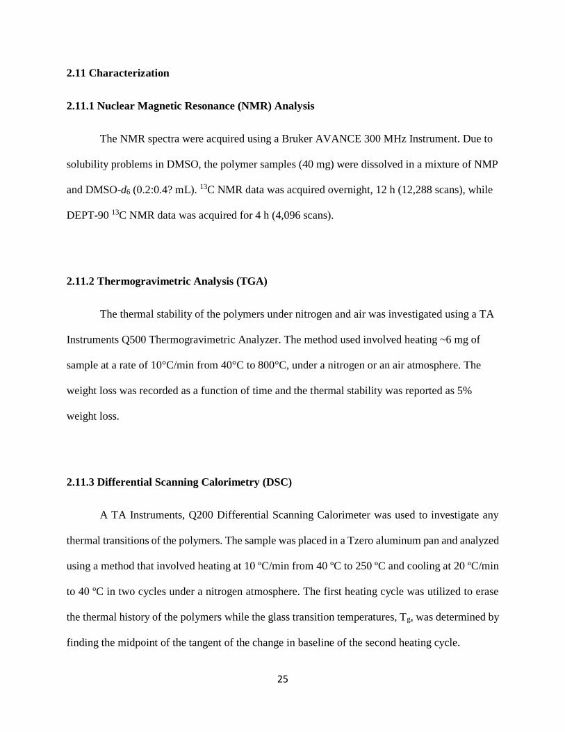
The NMR spectra were acquired using a Bruker AVANCE 300 MHz Instrument. Due to
solubility problems in DMSO, the polymer samples (40 mg) were dissolved in a mixture of NMP
and DMSO-d6 (0.2:0.4? mL). 13C NMR data was acquired overnight, 12 h (12,288 scans), while
DEPT-90 13C NMR data was acquired for 4 h (4,096 scans).
2.11.2 Thermogravimetric Analysis (TGA)
The thermal stability of the polymers under nitrogen and air was investigated using a TA
Instruments Q500 Thermogravimetric Analyzer. The method used involved heating ~6 mg of
sample at a rate of 10°C/min from 40°C to 800°C, under a nitrogen or an air atmosphere. The
weight loss was recorded as a function of time and the thermal stability was reported as 5%
weight loss.
2.11.3 Differential Scanning Calorimetry (DSC)
A TA Instruments, Q200 Differential Scanning Calorimeter was used to investigate any
thermal transitions of the polymers. The sample was placed in a Tzero aluminum pan and analyzed
using a method that involved heating at 10 ºC/min from 40 ºC to 250 ºC and cooling at 20 ºC/min
to 40 ºC in two cycles under a nitrogen atmosphere. The first heating cycle was utilized to erase
the thermal history of the polymers while the glass transition temperatures, Tg, was determined by
finding the midpoint of the tangent of the change in baseline of the second heating cycle.
Page 39
26
2.11.4 Absorption and Emission Spectra
The absorption and fluorescence spectra of monomers were first acquired from 5
millimolar solutions in THF and NMP. The absorption and fluorescence data for the monomers
were also acquired in both NMP and THF solvents at a concentration of 20 micromolar. Absorption
and emission for the polymers were acquired from NMP solutions, at a concentration of 20
micromolar, as well as in film form. The fluorescence of polymer films was measured by placing
the films at a 45⁰C angle to the incident light in the fluorescence spectrometer.
Page 40
27
3. RESULTS AND DISCUSSION
3.1 Synthesis of BOX-Br, 3
The synthesis of BOX-Br, 3, was achieved by the reaction of 3,5-difluorobenzoic acid, 1,
with 2-amino-4-bromophenol, 2, in the presence of polyphosphoric acid, PPA, (Scheme 7). 21, 22,
23 The method was previously used and described in the literature by Kashiyama et al. and also
used by Huong Hoang for the synthesis of 2-(3,5-difluorophenyl) benzothiazole and benzoxazole.
21, 22, 23 The structure of 3 is shown in Scheme 7; in this work, the 3,5-difluorophenyl unit is
considered to be the “upper ring”.
Scheme 7. Synthesis of BOX-Br, 3
An excess of 1 was first mixed with polyphosphoric acid and heated at 110 0C with stirring
until it formed a uniform mixture. Compound 2 was added into the reaction mixture and allowed
to react for 24 h. After the reaction was complete, polyphosphoric acid and excess 3,5-
difluorobenzoic acid were removed by precipitating the reaction mixture in excess water. The
product was recrystallized from ethanol to afford white crystals of 3 (98 % yield). The structure of
3 was confirmed by 1H and 13C NMR spectroscopy; the spectra are shown in Figures 7 and 8,
respectively.
Page 41
28
In the 1H NMR spectrum of 3 (Figure 7) the peak labelled a, at 7.01 ppm, is a triplet of
triplets, and is assigned to the proton on the upper phenyl ring between the two fluorine atoms.
The triplet of triplets is due to the coupling with the two chemically equivalent fluorine atoms (3JH-
F = 8.6 Hz) and the two protons in the meta-positions, with equal coupling constants (4JH-H = 2.4
Hz). The signal from proton labelled e appears at 7.46 ppm and is a doublet of doublets due to
ortho-coupling, with d (3JH-H=8.7 Hz), and para-coupling, with proton c (5JH-H=0.6 Hz). The signal
at 7.51 ppm is assigned to proton d; this is also a doublet of doublets due to ortho-coupling, with
e (3JH-H = 8.6 Hz), and meta-coupling with c (4JH-H = 1.8 Hz). The signal assigned to proton b is a
multiplet due to coupling with the two non-equivalent fluorines and with proton a. The peak at
7.91 ppm is a doublet of doublets and is assigned to c, the doublet of doublets is due to meta-
coupling, with d (4JH-H=1.8 Hz), and para-coupling, with e (5JH-H = 0.6 Hz).
Figure 7. 300 MHz 1H (CDCl3) NMR spectrum of BOX-Br, 3.
Page 42
29
The 13C NMR spectrum of 3 is shown Figure 8 and shows eleven unique peaks. The carbon
atoms assigned to a, d and e, appearing at 107.2, 129.5 and 163.4 ppm, respectively are all triplets
due to coupling with the two fluorine atoms. The signal for carbon a is the most upfield due to
resonance contributions from the two ortho fluorines, which increase electron density. Carbon b
appears as a doublet of doublets at 160.5-164.2 ppm, and is the most downfield due to strong
electron withdrawing ipso fluorine atom and the fluorine in the meta position. The carbon labeled
c appearing at 110.2-111.1 ppm is also a doublet of doublets due to the coupling with the two
fluorine atoms. Other signals at 110.9, 117.8, 123.4, 129.5, 143.3, 149.7 are identified as singlets
and are labeled g, h, j, i, f, and k, respectively.
Figure 8. 75.5 MHZ 13C NMR (CDCl3) spectrum of 3.
Page 43
30
3.2 Synthesis of BOX-CBZ, 5a
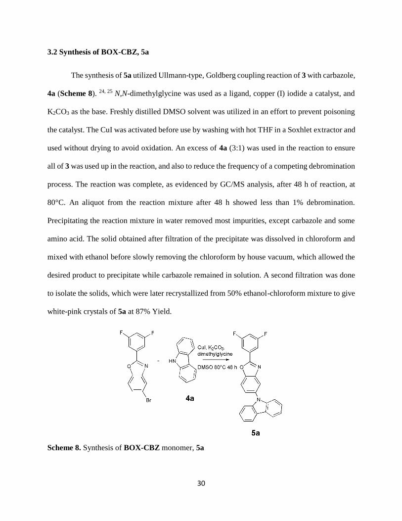
The synthesis of 5a utilized Ullmann-type, Goldberg coupling reaction of 3 with carbazole,
4a (Scheme 8). 24, 25 N,N-dimethylglycine was used as a ligand, copper (I) iodide a catalyst, and
K2CO3 as the base. Freshly distilled DMSO solvent was utilized in an effort to prevent poisoning
the catalyst. The CuI was activated before use by washing with hot THF in a Soxhlet extractor and
used without drying to avoid oxidation. An excess of 4a (3:1) was used in the reaction to ensure
all of 3 was used up in the reaction, and also to reduce the frequency of a competing debromination
process. The reaction was complete, as evidenced by GC/MS analysis, after 48 h of reaction, at
80°C. An aliquot from the reaction mixture after 48 h showed less than 1% debromination.
Precipitating the reaction mixture in water removed most impurities, except carbazole and some
amino acid. The solid obtained after filtration of the precipitate was dissolved in chloroform and
mixed with ethanol before slowly removing the chloroform by house vacuum, which allowed the
desired product to precipitate while carbazole remained in solution. A second filtration was done
to isolate the solids, which were later recrystallized from 50% ethanol-chloroform mixture to give
white-pink crystals of 5a at 87% Yield.
Scheme 8. Synthesis of BOX-CBZ monomer, 5a
Page 44
31
The monomer, 5a, was analyzed for purity using GC/MS (100 %), melting point 210-212
⁰C, elemental analysis (Theoretical; C=75.51%, H=3.54%. Found; C=75.48, H=3.58), and NMR
spectroscopy. The 1H NMR spectrum of 5a is shown in Figure 9.
Figure 9. 300 MHZ 1H NMR (CDCl3) spectrum of 5a.
As expected, the proton NMR spectrum showed nine unique peaks. The peak at 7.06 ppm
is a triplet of triplets and is assigned to proton a, between the two fluorine atoms, with coupling
constants similar to those observed in BOX-Br. Protons d and e are doublets of doublets and b is
a multiplet as in BOX-Br. New peaks, e, g, h and i, from carbazole are introduced into spectrum.
The peak labeled h, at 7.34 ppm, is a doublet of doublet of doublet due to coupling with two
inequivalent protons at ortho positions (i and g) and with one proton in the meta position, e, (3JH-H
= 7.7, 3JH-H= 6.1, 4JH-H= 2.1). The peaks at 7.48-7.40 ppm are multiplets and are assigned to
protons e and g. The peak labeled d, at 7.62 ppm is a doublet of doublets due to coupling with e
and with proton c. The peak labeled e, at 7.83 ppm is a doublet of doublets. The peak at 7.86 ppm
Page 45
32
is assigned to proton b, the peak is a multiplet due to coupling with two chemically inequivalent
fluorine atoms at the ortho and para position, and with the proton at meta position. At 8.02 ppm
is a doublet of doublets which is assigned to proton c, the doublet of doublets is due to coupling
with protons d and with c. The signal at 8.20 ppm is assigned to proton i, and is a multiplet due to
ortho coupling with h and also coupling with meta and para protons (e, g).
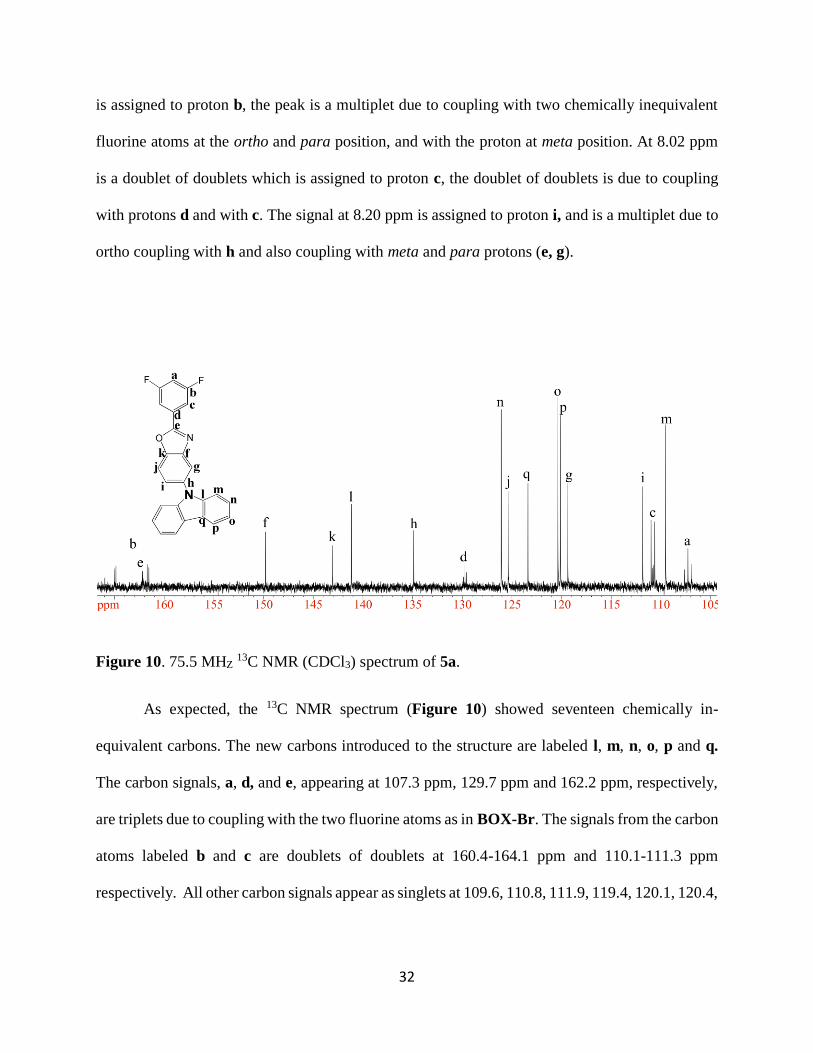
Figure 10. 75.5 MHZ 13C NMR (CDCl3) spectrum of 5a.
As expected, the 13C NMR spectrum (Figure 10) showed seventeen chemically in-
equivalent carbons. The new carbons introduced to the structure are labeled l, m, n, o, p and q.
The carbon signals, a, d, and e, appearing at 107.3 ppm, 129.7 ppm and 162.2 ppm, respectively,
are triplets due to coupling with the two fluorine atoms as in BOX-Br. The signals from the carbon
atoms labeled b and c are doublets of doublets at 160.4-164.1 ppm and 110.1-111.3 ppm
respectively. All other carbon signals appear as singlets at 109.6, 110.8, 111.9, 119.4, 120.1, 120.4,
Page 46
33
123.4, 125.4, 126.1, 134.9, 141.2, 143.01, 149.8, 151.5, and 163.3 ppm and are assigned as shown
in Figure 10.
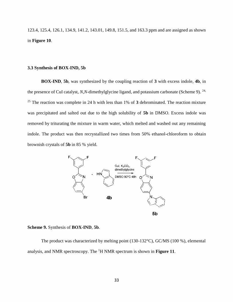
3.3 Synthesis of BOX-IND, 5b
BOX-IND, 5b, was synthesized by the coupling reaction of 3 with excess indole, 4b, in
the presence of CuI catalyst, N,N-dimethylglycine ligand, and potassium carbonate (Scheme 9). 24,
25 The reaction was complete in 24 h with less than 1% of 3 debrominated. The reaction mixture
was precipitated and salted out due to the high solubility of 5b in DMSO. Excess indole was
removed by triturating the mixture in warm water, which melted and washed out any remaining
indole. The product was then recrystallized two times from 50% ethanol-chloroform to obtain
brownish crystals of 5b in 85 % yield.
Scheme 9. Synthesis of BOX-IND, 5b.
The product was characterized by melting point (130-132°C), GC/MS (100 %), elemental
analysis, and NMR spectroscopy. The 1H NMR spectrum is shown in Figure 11.
Page 47
34
Figure 11. 300 MHZ 1H NMR (CDCl3) spectrum of BOX-IND monomer, 5b.
The signal from proton marked j, at 6.76 ppm is a doublet of doublets due to coupling with
k and j (4JH-H = 3.2, 5JH-H 0.6). The peak at 7.22 is assigned to proton labeled h, this is a multiplet
due to coupling with protons i, g, and f. Signal from proton g appears as a multiplet due to coupling
with proton f, h and i. The proton j, at 7.41 is a doublet of doublets due to coupling with k (3JH-
H=3.3 Hz) and with i. Other peaks and their coupling are identical to those observed in BOX-Br
and BOX-CBZ.
The 13C NMR spectrum of BOX-IND is shown in Figure 12. Eight new carbon atoms from indole
are introduced into the BOX-Br structure. Their signals are assigned as r, m, s, p, o, q, n and r,
appearing at 103.9, 110.3, 116.4, 121.2, 122.0, 123.1, 129.4, 137.2 ppm, respectively.
Page 48
35
Figure 12. 75.5 MHZ 13C NMR (CDCl3) spectrum of BOX-IND monomer.
3.4 Iodination of 2-(3,5-Difluorophenyl)-benzothiazole, BTZ (6)
2-(3,5-Difluorophenyl)-benzothiazole, 6, was synthesized via a previously reported route
involving the reaction of 3,5-difluorobenzoic acid with 2-aminothiophenol in the presence of
polyphosphoric acid. The proton and carbon NMR data agreed with the literature values.
Iodination was performed with N-iodosuccinimide, 7, (NIS) in concentrated sulfuric acid
(Scheme 10). NIS and BTZ were first dissolved separately in sulfuric acid and mixed with
vigorous stirring to reduce local concentration effects that might cause multiple iodinations to
occur. The reaction was allowed to stir at room temperature for 24 h, at which point GC/MS
analysis of an aliquot showed 78% mono (8a) and 11% diiodinated (8b), species present. The
reaction mixture was precipitated from excess water and washed with sodium bicarbonate
solution to remove the acid. The product was recrystallized from a mixture of ethanol, toluene,
and chloroform (1:1:8) to afford 52% yield of 8a.
Page 49
36
Scheme 10. Synthesis of BTZ-I, 8a.
The proton NMR spectrum of 8a displayed four peaks as shown in Figure 13. The peak
labeled a, at 6.97 ppm, is a triplet of triplets, and is assigned to the proton on the upper phenyl ring
between the two fluorine atoms. The triplet of triplets is due to the coupling with the two fluorines
with two chemically equivalent fluorine atoms (3JH-F = 8.5 Hz) and the two protons at the meta
position, with equal coupling constants (4JH-H = 2.4 Hz). The signal from proton b appears as a
multiplets while proton c showed a singlet. Protons labelled e and d showed overlapping
resonances, however their integration showed two protons. All the protons are assigned as shown
in Figure 13.
Page 50
37
Figure 13. 300 MHZ 1H NMR (CDCl3) spectrum of BTZ-I, 8a
3.5. Synthesis of BTZ-CBZ, 9
Monomer 9 was synthesized via a coupling reaction of BTZ-I, 8a, with 4a (Scheme 11).
The reaction was facilitated by a CuI catalyst and N,N-dimethylglycine ligand while K2CO3 was
used as the base. The reaction was carried out in DMSO solvent. 24, 25 Excess carbazole was used
to reduce de-iodination of BTZ-I. The reaction was complete in 24 h with less than 0.5% de-
iodination. The reaction mixture was precipitated from DI water to remove excess K2CO3 and CuI.
The mixture was filtered and the resulting solid was dissolved in chloroform and filtered again to
remove any remaining amino acid. Ethanol was added to the mixture and the chloroform was
removed under reduced pressure to allow the insoluble BTZ-CBZ to crystallize. The monomer
was further purified by recrystallization from 20% ethanol in chloroform to afford 78% yield of
BTZ-CBZ.
Page 51
38
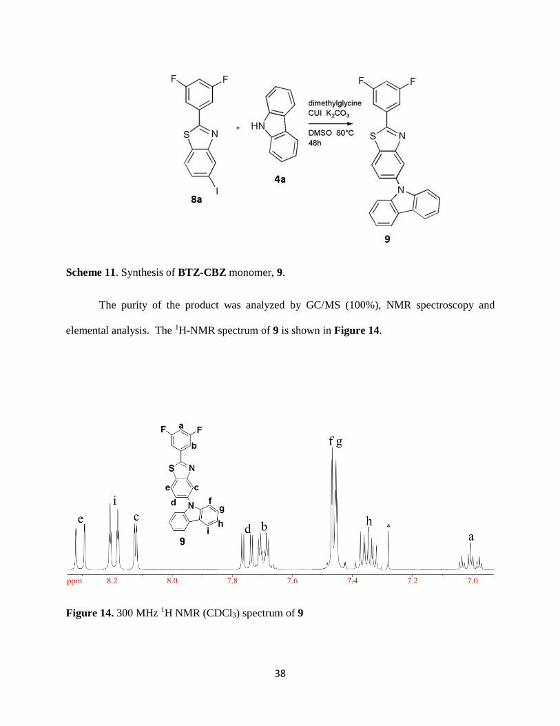
Scheme 11. Synthesis of BTZ-CBZ monomer, 9.
The purity of the product was analyzed by GC/MS (100%), NMR spectroscopy and
elemental analysis. The 1H-NMR spectrum of 9 is shown in Figure 14.
Figure 14. 300 MHz 1H NMR (CDCl3) spectrum of 9
Page 52
39
New peaks arising from the introduction of carbazole into BTZ-I are labelled f, g, h, and
i. The signal for the proton labeled h appears at 7.35 ppm and is a doublet of doublet of doublets
due to coupling with two inequivalent ortho protons, i and g and with the meta proton, f. The
signals for the protons labelled f and g, appearing at 7.41-7.44, are multiplets due to coupling
with each other and with protons h and i. Proton i is also a multiplet at 8.19 ppm.
Figure 15. 75.5 MHz 13C NMR (CDCl3) spectrum of 9
The 13C NMR spectrum (Figure 15) clearly shows the carbazole peaks l, m, n, o, p, and
q that were introduced into the BTZ-I structure and no C-I signal, ~ 95 ppm.
Page 53
40
3.6 UV and Fluorescence of BTZ-CBZ, BOX-CBZ and BOX-IND monomers
UV and Fluorescence data of the three monomers were acquired in THF at a concentration
of 20 μM. The data are presented in Figures 16a and 16b, respectively. BTZ-CBZ showed the
strongest absorption with max at 341 nm. The BOX-CBZ absorption intensity was a little less than
that of BTZ-CBZ with a maximum absorption at 339 nm while the BOX-IND monomer showed
the least intense absorption with a max at ~ 339 nm.
(a) (b)
Figure 16. (a) Absorption and (b) Fluorescence spectra of BTZ-CBZ, BOX-CBZ and BOX-
IND in THF, excited at 310nm.
All three monomers showed broad, but strong emission centered at about 460 nm. BTZ-
CBZ monomer showed the highest in emission intensity while BOX-IND had the lowest intensity
which may be due to weaker electron donating group, indole. Varying the excitation wavelength
from 250 nm to 340 nm changed the intensity of fluorescence, but the maximum emission
0
0.2
0.4
0.6
0.8
1
1.2
290 340 390
Ab
sorb
ance
Wavelength (nm)BOX-IND BTZ-CBZ BOX-CBZ
0
100
200
300
400
500
600
700
800
390 440 490 540 590
Inte
nsi
ty (
au)
Wavelength (nm)BOX-IND BOX-CBZ BTZ-CBZ
Page 54
41
wavelength remained unchanged. For all three monomers the highest fluorescence intensity was
observed between excitation wavelengths of 300-320 nm.
Figure 17. Fluorescence spectra of BTZ-CBZ, 9, in THF and in NMP, excited at 300 nm.
When the fluorescence of BTZ-CBZ monomer was compared in NMP and in THF
solvents (Figure 17), the more polar solvent, NMP, caused a large shift in emission wavelengths
towards longer wavelengths.This is bathocromic shift, which is observed in π-π* transitions, and
is caused by attractive polarisation forces between the solvent and the chromophores which lower
the energy levels of both the excited and unexcited states causing the shift to lower energy, red
shift in fluorescence.
0
100
200
300
400
500
600
700
800
900
1000
390 440 490 540 590
Inte
nsi
ty
Wavelength (nm)
THF
NMP
Page 55
42
3.7. Synthesis of copolymers 10a-10d, 11, and 12
Polymers 10a-10d, 11, and 12 were synthesized via typical Nucleophilic Aromatic
Substitution (NAS) polycondensation reactions (Scheme 12). 16, 17 K2CO3 and CaCO3 were used
to deprotonate 4,4’-biphenol with CaCO3 also helping to remove active fluoride by-products from
the reaction mixture. A polar aprotic solvent, NMP, was used to facilitate the reaction.
Scheme 12. Synthesis of polymers 10a-10d, 11, and 12.
The synthesis of homopolymer 10a was achieved by the reaction of bis-(4-
fluorophenyl)phosphine oxide and 4,4-biphenol in the presence of K2CO3 and NMP. The reaction
mixture precipitated well from DI water to give a white precipitate. The polymer formed clear and
flexible films when cast from NMP solutions of the polymer on a glass slide. Figure 18 displays
Page 56
43
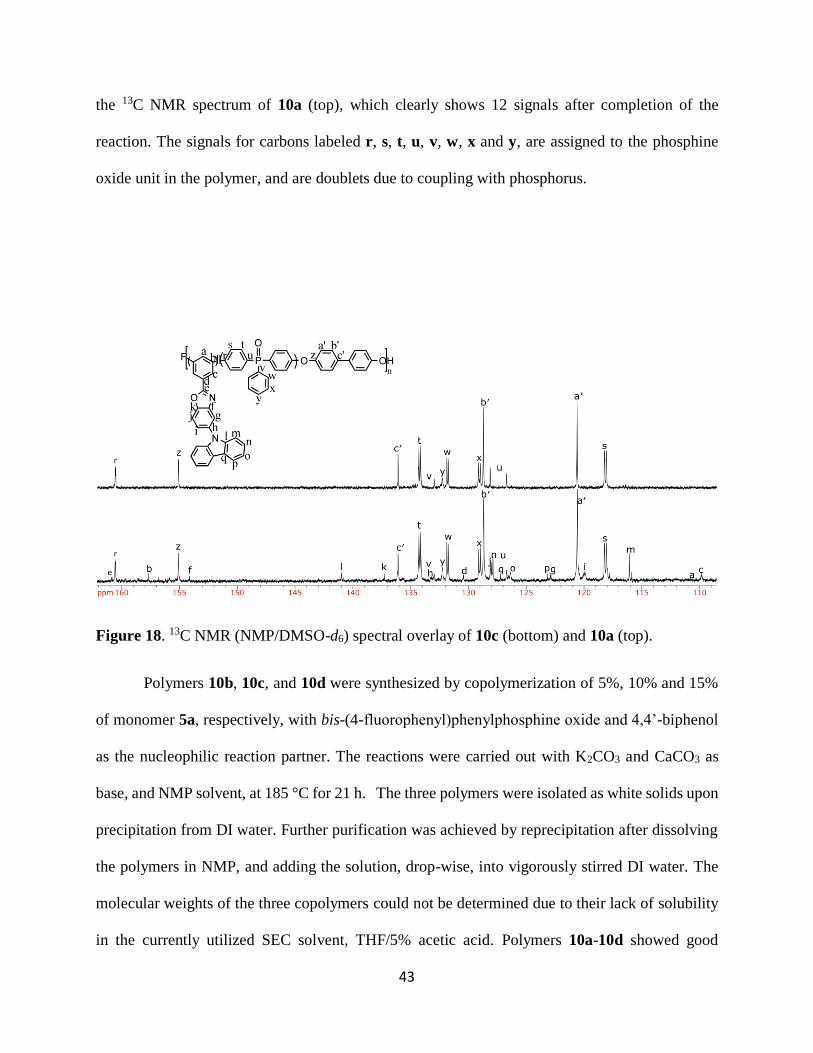
the 13C NMR spectrum of 10a (top), which clearly shows 12 signals after completion of the
reaction. The signals for carbons labeled r, s, t, u, v, w, x and y, are assigned to the phosphine
oxide unit in the polymer, and are doublets due to coupling with phosphorus.
Figure 18. 13C NMR (NMP/DMSO-d6) spectral overlay of 10c (bottom) and 10a (top).
Polymers 10b, 10c, and 10d were synthesized by copolymerization of 5%, 10% and 15%
of monomer 5a, respectively, with bis-(4-fluorophenyl)phenylphosphine oxide and 4,4’-biphenol
as the nucleophilic reaction partner. The reactions were carried out with K2CO3 and CaCO3 as
base, and NMP solvent, at 185 °C for 21 h. The three polymers were isolated as white solids upon
precipitation from DI water. Further purification was achieved by reprecipitation after dissolving
the polymers in NMP, and adding the solution, drop-wise, into vigorously stirred DI water. The
molecular weights of the three copolymers could not be determined due to their lack of solubility
in the currently utilized SEC solvent, THF/5% acetic acid. Polymers 10a-10d showed good
Page 57
44
solubility in NMP and dimethylacetamide (DMAC) solvents, but were insoluble in DMSO,
chloroform, and THF.
The reaction progress and polymer structure was confirmed by 13C NMR spectroscopy,
which showed clear changes in the signals originating from the carbon between the two fluorine
atoms, a triplet at 105 ppm, labelled a in the monomer. The signal changed from a triplet to a
doublet with displacement of one fluorine atom, then to a singlet when both fluorine atoms were
displaced, and the reaction was complete. Other peaks showed subtle changes in the spectrum
compared to their corresponding initial units due to formation of ether bonds in the polymerization
process. The 13C NMR spectrum (Figure 18) showed four tall peaks labelled z, a′, b′, and c′ from
the biphenol ring where a′ and b′ are the tallest and represent the signals from the two sets of
equivalent carbons. The signals from the phosphine oxide unit, r, s, t, u, v w, x and y appear as
doublets due to coupling with phosphorus, while those from the chromophore unit, 5a are singlets
and weak due to their low percentage in the polymer. The peaks for the respective carbon atoms
are assigned as shown in Figure 18.
Polymer films were prepared by dissolving the copolymers in NMP and then casting onto
glass slides. The copolymers 10b and 10c, containing 5% and 15% BOX-CBZ gave flexible and
transparent films, while films from 10d, having 25% of 5a, were brittle.
Synthesis of copolymer 11 was done in the same way as all the other polymers, but with
15% of monomer 9. To ensure purity, polymer 11 was dissolved in NMP solvent and left to settle
overnight before glasswool filtration and reprecipitation. The polymer showed good solubility in
NMP, but was insoluble in chloroform, DMSO, and THF solvents. A polymer film was cast from
NMP solvent on a glass film, which showed a strong attraction to the glass slide. However, soaking
Page 58
45
the glass slide in water allowed the film to be removed.The UV and fluorescence data were
acquired in NMP solvent and from the polymer film.
The polymer structure was also confirmed by NMR analysis (Figure 19) in a NMP and
DMSO-d6 solvent mixture (2:5). Also, 13C NMR spectroscopy was used to monitor the progress
of the polymerization reactions. A triplet \ signal, usually appearing at about 105 ppm in monomer
9, changes to a doublet with displacement of one fluorine atom, and finally, to a singlet when the
reaction is complete. Also, the polymer showed slight changes in the chemical shifts compared to
their initial units due to the formation of ether bonds.
Figure 19. 13C NMR (NMP/DMSO-d6) overlay of 11 and 10a.
Page 59
46
Polymer 12 was synthesized in the same way as polymers 10a-10d, but with 15% of
monomer 5b. The polymer was isolated by first diluting with NMP, followed by drop-wise
addition of the mixture into vigorously stirred DI water to afford a white precipitate of 12. The
polymer was purified by dissolving in NMP and allowing impurities to settle overnight, before
filtering with glass wool and reprecipitating from DI water. The polymer showed a higher
solubility in NMP than all the other polymers, but was insoluble in chloroform and DMSO.
Flexible, transparent and stress resistant films were formed when the polymer was cast on a glass
substrate from NMP solvent. The polymer structure was confirmed by NMR analysis (Figure 20).
Figure 20. 13C NMR (NMP/DMSO-d6) overlay of 12 (bottom) and 10a (top).
Page 60
47
3.11 Thermal Analysis
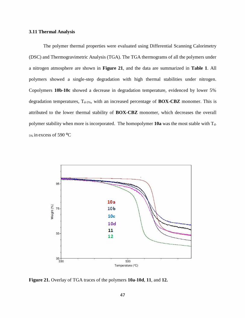
The polymer thermal properties were evaluated using Differential Scanning Calorimetry
(DSC) and Thermogravimetric Analysis (TGA). The TGA thermograms of all the polymers under
a nitrogen atmosphere are shown in Figure 21, and the data are summarized in Table 1. All
polymers showed a single-step degradation with high thermal stabilities under nitrogen.
Copolymers 10b-10c showed a decrease in degradation temperature, evidenced by lower 5%
degradation temperatures, Td-5%, with an increased percentage of BOX-CBZ monomer. This is
attributed to the lower thermal stability of BOX-CBZ monomer, which decreases the overall
polymer stability when more is incorporated. The homopolymer 10a was the most stable with Td-
5% in excess of 590 ⁰C
Figure 21. Overlay of TGA traces of the polymers 10a-10d, 11, and 12.
Page 61
48
Polymer Tg ⁰C Td-5% ⁰C
Homopolymer (10a) 232 590
5% BOX-CBZ (10b) 232 517
15% BOX-CBZ (10c) 236 507
25% BOX-CBZ (10d) 235 472
15% BTZ-CBZ (11) 243 525
15% BOX-IND (12) 210 467
Table 1. Glass transition temperatures, Tg, and 5% degradation temperatures, Td-5%, under
nitrogen atmospheres for polymers 10a-10d, 11, and 12
An overlay of the DSC traces of the six polymers is shown in Figure 22 and summarized
in Table 1. The DSC traces clearly indicate that polymer 12 has the lowest glass transition
temperature of all the polymers; this is attributed to the asymmetrical monomer structure. BTZ-
CBZ copolymer showed the highest glass transition temperature, 243 ⁰C this is due to the highly
rigid polymer structure, which limits rotation around sigma bonds in the polymer backbone.
Polymers 10b-10d showed increasing glass transition temperatures from 5% to 25% monomer
concentration. This is due to an increase in the more bulky pendent group which makes the polymer
more rigid and hence raising the glass transition temperature. DSC showed no other polymer
thermal transitions and hence the polymer were completely amorphous. The homopolymer, 10a
also had a high glass transition temperature of 232 ⁰C, which may be due to decreased free volume
which raises the glass transition temperature.
Page 62
49
Figure 22. DSC traces of polymers 10a-10d, 11 and 12 under nitrogen at a heating rate of 10 °
C/min.
Page 63
50
4. Absorption and Emission
Polymer absorption and fluorescence data were acquired in NMP solutions at a
concentration of 20 micromolar as well as from the polymers in film form. Figure 23 illustrates
the UV and fluorescence spectra of polymers 10b-10d acquired in NMP solutions. The copolymers
showed strong absorptions from 262 nm to 344 nm. At 300 nm to 345 nm, the decrease in
intensities of absorption follows the order of the decrease in percentage of chromophore in the
polymer, this indicates that the absorption above 300 nm is attributed to monomer present in the
polymer.
(a) (b)
Figure 23. Absorption (a) and emission (b) spectra of the BOX-CBZ copolymers, 10b (5 %),
10c (15 %), and 10d (25 %), excited at 315 nm.
An overlay of fluorescence spectra of 10b-10d is shown in Figure 23b. The 15% and 25%
copolymers showed maximum fluorescence peaks at 473 nm. Polymer 10d, containing 25 %
chromophore showed the highest fluorescence intensity due to high percentage of chromophore in
0
0.2
0.4
0.6
0.8
1
1.2
1.4
263 283 303 323 343 363
Ab
sorb
ance
Wavelenth (nm)
5% 15% 25%
0
20
40
60
80
100
120
350 450 550
Inte
nsi
ty
Wavelenth (nm)
5% 15% 25%
Page 64
51
the polymer. The 5% copolymer, 10b showed the weakest fluorescence also due to low percentage
of the chromophore. Interestingly, the emission maximum for 10b was centered at ~ 400 nm, with
a broad secondary peak centered at ~ 460 nm.
The solution fluorescence data of homopolymer, 10a and copolymers containing 15%
chromophore, 10c, 11, and 12 in NMP is shown in Figure 24a. The BTZ-CBZ copolymer, 11,
showed nearly four and a half times higher emission intensity than the BOX-CBZ copolymer,
while the BOX-IND copolymer, 12 had the weakest fluorescence. Polymer 11 had a maximum
intensity at 491 nm with no shoulder peaks. Polymer 10c had a maximum fluorescence at 473 nm
and a smaller peak at 403 nm. Polymer 12 showed the weakest fluorescence and lowest emission
maximum, ~ 416 nm.
(a) (b)
Figure 24. (a) Fluorescence of copolymers containing 15% BOX-CBZ, BOX-IND, BTZ-
CBZ, and TPPO-BIPHE homopolymer in NMP. (b) Fluorescence of monomer 9 and
polymer 11 excited at 315 nm in NMP solute+-56ion.
0
100
200
300
400
500
600
700
360 460 560
Axi
s Ti
tle
Wavelength (nm)
15% BOX-CBZ BOX-IND
15% BTZ-CBZ TPPO-BIPHE
0
100
200
300
400
500
600
700
800
900
1000
360 460 560
Inte
nsi
ty
Wavelenth (nm)
15% BTZ-CBZ copolymerBTZ-CBZ monomer
Page 65
52
All of the polymers showed significant differences in fluorescence when compared to their
corresponding monomers in NMP. Monomer 9, Figure 24b, showed maximum fluorescence
wavelength centered at 500 nm, while its copolymer, 11, showed maximum wavelength at 481 nm
in NMP solvent.
Figure 25. Fluorescence from films of polymers 10c, 11, and 12, containing 15% chromophore,
excited at 315 nm
Fluorescence of the three copolymers was also measured on films cast onto glass slides.
The films were excited at different wavelengths (280-350 nm). In all polymers, the highest
intensities were observed with an excitation wavelength of 315 nm. The fluorescence of polymer
films from excitation wavelength of 315 nm is shown in Figure 25. The BTZ-CBZ copolymer
showed a narrow and high intensity fluorescence at about 451 nm. The BOX-CBZ copolymer
0
100
200
300
400
500
600
700
0 100 200 300 400 500 600 700
Inte
nsi
ty
Wavelenth (nm)
BOX-CBZ copolymer BTZ-CBZ copolymer BOX-IND copolymer
Page 66
53
showed a weaker and broader emission at 432 nm, while the BOX-IND copolymer had the weakest
emission, which was centered at 430 nm.
Comparing the fluorescence of polymer in films to their solutions in NMP, a large shift to
longer wavelengths is observed in solvent which is due to attractive polarization forces between
the solvents and the chromophores, which lower the energy levels excited states causing a ‘red
shift’.
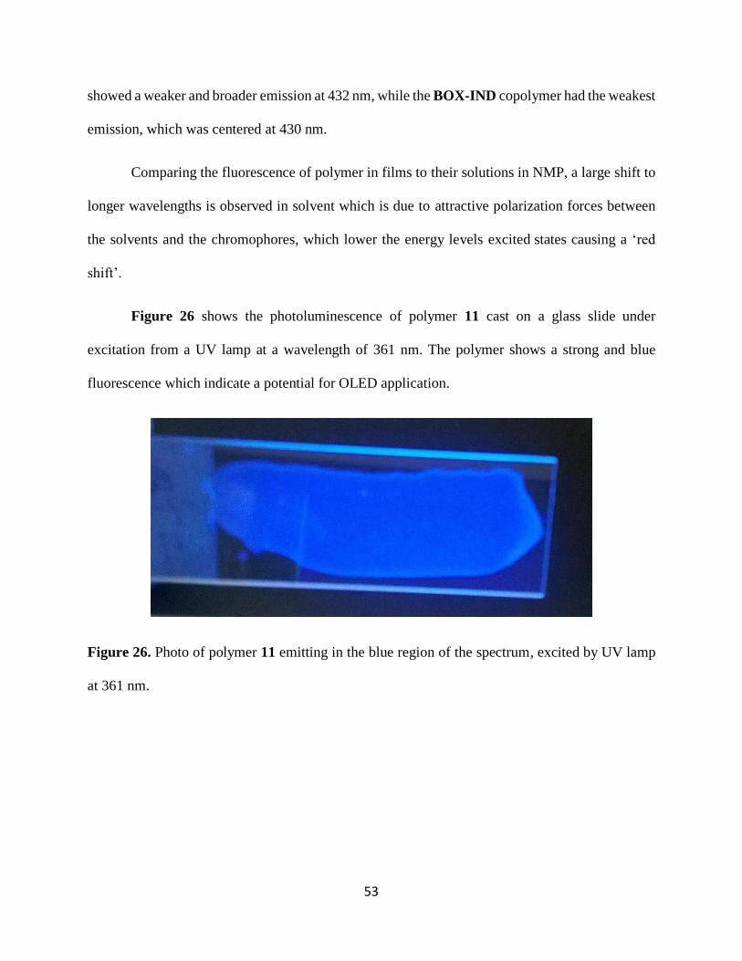
Figure 26 shows the photoluminescence of polymer 11 cast on a glass slide under
excitation from a UV lamp at a wavelength of 361 nm. The polymer shows a strong and blue
fluorescence which indicate a potential for OLED application.
Figure 26. Photo of polymer 11 emitting in the blue region of the spectrum, excited by UV lamp
at 361 nm.
Page 67
54
4. CONCLUSION
Fluorescent monomers 9-[2-(3,5-Difluorophenyl)-benzoxazol-5-yl]-9H-carbazole (BOX-
CBZ), 9-[2-(3,5-Difluorophenyl)-benzothiazol-5-yl]-9H-carbazole (BTZ-CBZ), and 2-(3,5-
Difluorophenyl)-5-indol-1-yl-benzooxazole (BOX-IND), were successfully synthesized via
copper (I) catalyzed amination reactions of either 5-Bromo-2-(3,5-difluorophenyl)-benzooxazole
and 5-Bromo-2-(3,5-difluorophenyl)-benzothiazole. All the monomers showed strong absorption
at wavelengths of 280 nm to 340 nm. The fluorescence analysis showed strong emission at about
463 nm in THF and 470 nm to 502 nm in NMP. Fluorescence of the three monomers in THF
solution showed different emission intensities, but very similar emission wavelengths. The
monomer solutions in NMP solvent showed significant differences; BTZ-CBZ emitted with a
strong intensity at 501 nm, BOX-CBZ at 505 nm and BOX-IND at 509 nm.
The monomers were successfully copolymerized with bis-(4-fluorophenyl)-phenyl
phosphine oxide and 4,4’-Biphenol via typical NAS reactions. The copolymers showed good
solubility in NMP and dimethylacetamide (DMAC) solvents at room temperature, but were
insoluble in most other solvents such as DMSO, THF, and toluene. All polymers, with the
exception of the 25% BOX-CBZ copolymer, formed good films when cast on glass slides.
The polymers showed high heat stability with 5 % weight loss temperatures in excess of
450⁰C and glass transition temperatures above 200 °C. The BTZ-CBZ copolymer showed both
the highest glass transition (number here) and degradation temperature (number here) while the
BOX-IND copolymer showed the lowest Tg (insert number here). The BOX-CBZ copolymers
showed an increase in Tg with an increase in the percentage of the BOX-CBZ monomer
incorporated into the polymer. Most likely this is due to the bulky pendent group in the monomer
which hinders the rotation around sigma bonds. The same polymers show decreasing thermal
Page 68
55
stability with an increase in the percentage of BOX-CBZ monomer, thus, it can be inferred that
the BOX-CBZ monomer is susceptible to heat and therefore lowers the polymer stability at high
temperatures.
All of the polymers showed strong absorptions between 290 nm and 340 nm when
measured in NMP solution. Fluorescence spectra showed distinct emission peaks at 481nm for 11,
473 nm for 10c and 410 nm for 12. Analysis of the fluorescence data from polymer films showed
true blue emission from the BTZ-CBZ copolymer, with a maximum wavelength of 451 nm. The
BOX-CBZ and BOX-IND copolymers emitted at 432 nm and 430 nm, respectively.
Page 69
56
5. PROPOSED WORK
Current studies have shown the potential for development of blue OLED emitters based on
benzoxazole and benzothiazole. The monomers can be easily polymerized to form PAE-based
fluorescent polymers for OLED applications.
In order to improve the monomer synthesis and percent yields, other methods of
halogenation need to be explored to avoid the formation of dihalogenated products. The amination
reaction also needs to be optimized by using other catalysts or different routes of synthesis. Other
synthetic routes also need to be investigated to be able to attach other heterocyclic species to the
monomer. Polymerization reactions also need to be investigated to determine better ways of
eliminating fluoride ions formed during the reaction which may be causing degradation of
monomers.
To obtain different colors from the polymer fluorescence, other electron rich groups and
amines need to be investigated to determine their donor-acceptor properties and emission
wavelengths when attached to acceptor-type monomers.
The current study makes use of benzoxazole and benzothiazole pendent to the polymer
chain, as such, the “inline” versions of BTZ and BOX are also potential candidates for fluorescent
materials and need to be studied to determine their potential for OLED applications.
Page 70
57
6. REFERENCES
1. Li, Z. R.; Meng, H. Organic Light-Emitting Materials and Devices; CRC/Taylor & Francis:
Boca Raton, Fl, 2007; pp. 2–17.
2. Kafafi, Z. Organic electroluminescence; CRC Press/Taylor & Francis: Boca Raton, FL, 2005;
pp. 1-8.
3. Templier, F. Overview of OLED Displays. Technology and Applications, OLED
Microdisplays. 2014, 35–51.
4. Collison, C.; Treemaneekarn, V.; Oldham, W.; Hsu, J.; Rothberg, L. Aggregation Effects
on the Structure and Optical Properties of a Model PPV Oligomer. Synthetic Metals. 2001, 119,
515–518.
5. Andersson, M.; Yu, G.; Heeger, A. Photoluminescence And Electroluminescence of Films
from Soluble PPV-Polymers. Synthetic Metals. 1997, 85, 1275–1276.
6. Yamaguchi, Y.; Tanaka, T.; Kobayashi, S.; Wakamiya, T.; Matsubara, Y.; Yoshida, Z.-I.
Light-Emitting Efficiency Tuning Of Rod-Shaped π Conjugated Systems by Donor and Acceptor
Groups. J. Am. Chem. Soc. Journal of the American Chemical Society. 2005, 127, 9332–9333.
7. Brunner, K.; Dijken, A. V.; Börner, H.; Bastiaansen, J. J. A. M.; Kiggen, N. M. M.;
Langeveld, B. M. W. Carbazole Compounds As Host Materials for Triplet Emitters in Organic
Light-Emitting Diodes: Tuning the HOMO Level without Influencing the Triplet Energy in Small
Molecules. J. Am. Chem. Soc. Journal of the American Chemical Society. 2004, 126, 6035–6042.
Page 71
58
8. Gong, Y.; Guo, X.; Wang, S.; Su, H.; Xia, A.; He, Q.; Bai, F. Photophysical Properties Of
Photoactive Molecules with Conjugated Push−Pull Structures. J. Phys. Chem. The Journal of
Physical Chemistry A. 2007, 111, 5806–581
9. Gupta, A.; Watkins, S. E.; Scully, A. D.; Singh, T. B.; Wilson, G. J.; Rozanski, L. J.; Evans,
R. A. Band-Gap Tuning of Pendant Polymers for Organic Light-Emitting Devices and
Photovoltaic Applications. Synthetic Metals. 2011, 161, 856–863.
10. Gong, Y.; Guo, X.; Wang, S.; Su, H.; Xia, A.; He, Q.; Bai, F. Photophysical Properties Of
Photoactive Molecules with Conjugated Push−Pull Structures. J. Phys. Chem. 2007, 111, 5806–
5812.
11. Patra, A.; Pan, M.; Friend, C. S.; Lin, T.-C.; Cartwright, A. N.; Prasad, P. N.; Burzynski,
R. Electroluminescence Properties Of Systematically Derivatized Organic Chromophores
Containing Electron Donor and Acceptor Groups. Chemistry of Materials Chem. Mater. 2002, 14,
4044–4048.
12. Basavaraja, J.; Inamdar, S.; Kumar, H. S. Solvents Effect on the Absorption and
Fluorescence Spectra of 7-Diethylamino-3-Thenoylcoumarin: Evaluation and Correlation between
Solvatochromism and Solvent Polarity Parameters. Spectrochimica Acta Part A: Molecular and
Biomolecular Spectroscopy. 2015, 137, 527–534.
13. Zhang, C.; Kang, S.; Ma, X.; Xiao, G.; Yan, D. Synthesis And Characterization of
Sulfonated Poly(Arylene Ether Phosphine Oxide)s with Fluorenyl Groups by Direct
Polymerization for Proton Exchange Membranes. Journal of Membrane Science. 2009, 323, 99–
105.
Page 72
59
14. Smith, C. D.; Grubbs, H.; Webster, H.F.; Gungor, A.; Wightman, J. P.; McGrath, J. E.
Unique Characteristics Derived from Poly( Arylene Ether Phosphine Oxide)s. High Performance
Polymers. 1991, 3, 211–229.
15. Andrejevic, M.; Schmitz, J.; Fossum, E. Poly(Arylene Ether)s Derived from N-Alkyl-N-
Phenyl-3,5-Difluorobenzene Sulfonamides: Effect of Alkyl Chain Length on the Glass Transition
Temperature. Materials Today Communications. 2015, 3, 10–16.
16. Beek, D. V.; Fossum, E. Linear Poly(Arylene Ether)s with Pendant Benzoyl Groups:
Geometric Isomers of PEEK or Substituted Poly(Phenylene Oxide) Macromolecules. 2009, 42,
4016–4022.
17. Kaiti, S.; Himmelberg, P.; Williams, J.; Abdellatif, M.; Fossum, E. Linear Poly(arylene
ether)s with Pendant Phenylsulfonyl Groups: Nucleophilic Aromatic Substitution Activated from
the Meta Position. Macromolecules 2006, 39, 7909-7914.
18. Hedrick, J. L. Poly(aryl ether benzothiazole)s. Macromolecules. 1991, 24, 6361–6364.
19. Hilborn, J. G.; Labadie, J. W.; Hedrick, J. L. Poly(aryl ether-benzoxazole)s.
Macromolecules. 1990, 23, 2854–2861.
20. Hedrick, J. L.; Jonsson, H.; Carter, K. R. Poly(Aryl Ether)s Containing Pendent
Benzoxazole and Benzothiazole Units. Macromolecules. 1995, 28, 4340–4343.
21. Huang L, H. Hydroquinone-based poly(arylene ether)s with pendent benzothiazole or
benzoxazole and 3-sulfonated phenyl sulfonyl groups for use as proton exchange membranes.
masters, wright state university, 2013.
Page 73
60
22. So, Y.-H.; Heeschen, J. P. Mechanism Of Polyphosphoric Acid and Phosphorus
Pentoxide−Methanesulfonic Acid as Synthetic Reagents for Benzoxazole Formation. The Journal
of Organic Chemistry J. Org. Chem. 1997, 62, 3552–3561.
23. Kashiyama, E.; Hutchinson, I.; Chua, M.-S.; Stinson, S. F.; Phillips, L. R.; Kaur, G.;
Sausville, E. A.; Bradshaw, T. D.; Westwell, A. D.; Stevens, M. F. G. Antitumor Benzothiazoles.
8. 1 Synthesis, Metabolic Formation, And Biological Properties of the C - and N -Oxidation
Products of Antitumor 2-(4-Aminophenyl)Benzothiazoles . J. Med. Chem. Journal of Medicinal
Chemistry. 1999, 42, 4172–4184.
24. Irma Goldberg,"Ueber Phenylirungen bei Gegenwart von Kupfer als Katalysator". Berichte
der deutschen chemischen Gesellschaft, 1906. 39 (2): 1691–1692.
25. Zhang, H.; Cai, Q.; Ma, D. Amino Acid Promoted CuI-Catalyzed C−N Bond Formation
Between Aryl Halides and Amines or N-Containing Heterocycles. The Journal of Organic
Chemistry J. Org. Chem. 2005, 70, 5164–5173.