Design and Characterization of Liquid Crystal-Graphite Composite Electrodes Afsaneh Safavi* and Maryam Tohidi Department of Chemistry, College of Sciences, Shiraz UniVersity, Shiraz, 71454, Iran ReceiVed: December 2, 2009; ReVised Manuscript ReceiVed: January 12, 2010 Thermotropic ionic liquid crystals (ILCs), 1,1′-dialkyl-4,4′-bipyridinium bis(triflimide)s have been used as binders to fabricate new carbon composite electrodes. ILC compounds possess an ordered molecular orientation, and upon mixing with graphite, ILCs retain their liquid crystal characteristics and thus their ordered arrangement. The electrochemical performances of these composite electrodes were evaluated by using different electrochemical probes. The resulting electrodes offer high electrochemical reactivity, low background current, improved signal-to-noise ratio, greater stability, excellent mechanical strength, and very good antifouling effects. It is believed that the higher conductivity of ILCs as well as the ordered orientation of these thermotropic ILCs which cause an increase in the edge-plane sites of these composite electrodes are responsible for the promotion of their electrocatalytic activities and antifouling effects. Such characteristics make these composite electrodes ideal for use in different electrochemical and biosensing applications. Introduction Liquid crystals (LCs) are considered as the fourth state of matter. 1 The LC state is a physical state with a structure intermediate between a crystalline solid and an isotropic liquid. The molecules in a LC possess the mobility of molecules in a liquid, but they maintain some degree of long-range order. Most LCs are neutral organic compounds. The driving forces for the formation of a liquid-crystalline phase (mesophase) are the interactions between the anisometric molecules (dipole-dipole interactions, van der Waals interactions, π-π stacking, and so forth). 2 Thermotropic LCs are compounds that form a mesophase upon heating the solid state or/and upon cooling the isotropic liquid. 2 Enantiotropic thermotropic LCs can be changed into the LC state from either lowering the temperature of an isotropic liquid or raising the temperature of a solid. Since the discovery of LCs, a variety of LCs have been investigated and used in many fields. Flat panel displays represent the most popular use of LCs. 3 The important applications of LCs in analytical chemistry involves their use as stationary phases in order to separate different compounds in gas chromatographgy, 4–7 high-performance liquid chromatography (HPLC), 8–11 open tubular capillary electrochromatography, 12,13 capillary gel electrophoresis 14 and supercritical-fluid chromatography. 15,16 LCs have also been used as sensitive materials in the field of chemical and biological sensors. They can be used as membrane materials (membrane solvent and neutral carrier) for preparation of potentiometric neutral- carrier-type ion sensors (ion selective electrodes) 17–19 and ampero- metric sensors. 20 In other works, the LCs can be used as sensing layers or phases, and the orientational transition of the LCs can alter their optical appearance and can be used for design of the other sensors. 21–23 Ionic liquid crystals (ILCs) are a class of LC compounds that contain anions and cations. The ionic character means that some of the properties of the ILCs differ significantly from those of conventional LCs. Typical for ILCs is the ion conductivity. 2 ILCs have many different types of mesophases. 24,25 The nematic phase (N) is the least ordered mesophase exhibited by rod-like molecules. This phase can be considered as a one-dimensionally ordered elastic fluid, with orientational order of the molecules but without long-range positional ordering. In the nematic phase, the rod-like molecules tend to align themselves parallel to each other. A nematic phase is only in a very few cases observed for ILCs, although this phase is omnipresent in the case of neutral mesomorphic organic compounds. In the smectic (Sm) mesophases, the mesogenic molecules are situated in layers. The Sm phase is the most common phase for ILCs. 2 ILCs can be considered as materials that combine the properties of LCs and ionic liquids (ILs). 2 Worldwide intense research activity in the field of ILs is presently going on. 26–33 Because the properties of ILs (miscibility with water and other solvents, dissolving ability, polarity, viscosity, density, and so forth) can be tuned by an appropriate choice of the anion and the cation, ILs are often considered as designer solvents. These ILs can also be used to immobilize transition-metal catalysts in the liquid phase of biphasic catalytic reactions. Other applica- tions include their use as solvents for extraction processes and as electrolyte for batteries, fuel cells, and dye-sensitized solar cells. 2 In recent years, ILs have found a new role in analytical chemistry. The use of ILs as binder in place of non-conductive organic binders for the preparation of carbon ionic liquid electrodes (CILEs) 34,35 and application of these electrodes for the quantitative determination of different materials have been reported, which confirmed the high-performance electrochemical behavior of CILEs. 36–42 In one application, the effect of operating IL-carbon paste electrodes at temperatures above and below room temperature and their analytical performance in terms of stability and sensitivity were investigated. 43 However, to the best of our knowledge, there is no report on the use of ILCs as binders in carbon paste electrodes. Thus, it is important to investigate whether the incorporation of ILCs into graphite can result in an electrode surface with a layered morphology which in turn can induce an increase in edge-plane sites on the electrode surface. These edge-plane-like defects are crucial to the understanding of some of the surface chemistry and the electrochemical behavior. In fact, it is well established that the presence of edge planes on the electrode surface can increase * Corresponding authors. E-mail: [email protected]. J. Phys. Chem. C 2010, 114, 6132–6140 6132 10.1021/jp9114354 2010 American Chemical Society Published on Web 03/10/2010
Transcript
Design and Characterization of Liquid Crystal-Graphite Composite Electrodes
Afsaneh Safavi* and Maryam TohidiDepartment of Chemistry, College of Sciences, Shiraz UniVersity, Shiraz, 71454, Iran
ReceiVed: December 2, 2009; ReVised Manuscript ReceiVed: January 12, 2010
Thermotropic ionic liquid crystals (ILCs), 1,1′-dialkyl-4,4′-bipyridinium bis(triflimide)s have been used asbinders to fabricate new carbon composite electrodes. ILC compounds possess an ordered molecular orientation,and upon mixing with graphite, ILCs retain their liquid crystal characteristics and thus their ordered arrangement.The electrochemical performances of these composite electrodes were evaluated by using differentelectrochemical probes. The resulting electrodes offer high electrochemical reactivity, low background current,improved signal-to-noise ratio, greater stability, excellent mechanical strength, and very good antifoulingeffects. It is believed that the higher conductivity of ILCs as well as the ordered orientation of these thermotropicILCs which cause an increase in the edge-plane sites of these composite electrodes are responsible for thepromotion of their electrocatalytic activities and antifouling effects. Such characteristics make these compositeelectrodes ideal for use in different electrochemical and biosensing applications.
Introduction
Liquid crystals (LCs) are considered as the fourth state ofmatter.1 The LC state is a physical state with a structureintermediate between a crystalline solid and an isotropic liquid.The molecules in a LC possess the mobility of molecules in aliquid, but they maintain some degree of long-range order. MostLCs are neutral organic compounds. The driving forces for theformation of a liquid-crystalline phase (mesophase) are theinteractions between the anisometric molecules (dipole-dipoleinteractions, van der Waals interactions, π-π stacking, and soforth).2
Thermotropic LCs are compounds that form a mesophaseupon heating the solid state or/and upon cooling the isotropicliquid.2 Enantiotropic thermotropic LCs can be changed intothe LC state from either lowering the temperature of an isotropicliquid or raising the temperature of a solid.
Since the discovery of LCs, a variety of LCs have beeninvestigated and used in many fields. Flat panel displays representthe most popular use of LCs.3 The important applications of LCsin analytical chemistry involves their use as stationary phases inorder to separate different compounds in gas chromatographgy,4–7
high-performance liquid chromatography (HPLC),8–11 open tubularcapillary electrochromatography,12,13 capillary gel electrophoresis14
and supercritical-fluid chromatography.15,16 LCs have also beenused as sensitive materials in the field of chemical and biologicalsensors. They can be used as membrane materials (membranesolvent and neutral carrier) for preparation of potentiometric neutral-carrier-type ion sensors (ion selective electrodes)17–19 and ampero-metric sensors.20 In other works, the LCs can be used as sensinglayers or phases, and the orientational transition of the LCs canalter their optical appearance and can be used for design of theother sensors.21–23
Ionic liquid crystals (ILCs) are a class of LC compounds thatcontain anions and cations. The ionic character means that someof the properties of the ILCs differ significantly from those ofconventional LCs. Typical for ILCs is the ion conductivity.2
ILCs have many different types of mesophases.24,25 The nematicphase (N) is the least ordered mesophase exhibited by rod-like
molecules. This phase can be considered as a one-dimensionallyordered elastic fluid, with orientational order of the moleculesbut without long-range positional ordering. In the nematic phase,the rod-like molecules tend to align themselves parallel to eachother. A nematic phase is only in a very few cases observedfor ILCs, although this phase is omnipresent in the case ofneutral mesomorphic organic compounds. In the smectic (Sm)mesophases, the mesogenic molecules are situated in layers. TheSm phase is the most common phase for ILCs.2
ILCs can be considered as materials that combine theproperties of LCs and ionic liquids (ILs).2 Worldwide intenseresearch activity in the field of ILs is presently going on.26–33
Because the properties of ILs (miscibility with water and othersolvents, dissolving ability, polarity, viscosity, density, and soforth) can be tuned by an appropriate choice of the anion andthe cation, ILs are often considered as designer solvents. TheseILs can also be used to immobilize transition-metal catalysts inthe liquid phase of biphasic catalytic reactions. Other applica-tions include their use as solvents for extraction processes andas electrolyte for batteries, fuel cells, and dye-sensitized solarcells.2
In recent years, ILs have found a new role in analyticalchemistry. The use of ILs as binder in place of non-conductiveorganic binders for the preparation of carbon ionic liquidelectrodes (CILEs)34,35 and application of these electrodes forthe quantitative determination of different materials have beenreported, which confirmed the high-performance electrochemicalbehavior of CILEs.36–42 In one application, the effect of operatingIL-carbon paste electrodes at temperatures above and belowroom temperature and their analytical performance in terms ofstability and sensitivity were investigated.43 However, to thebest of our knowledge, there is no report on the use of ILCs asbinders in carbon paste electrodes. Thus, it is important toinvestigate whether the incorporation of ILCs into graphite canresult in an electrode surface with a layered morphology whichin turn can induce an increase in edge-plane sites on theelectrode surface. These edge-plane-like defects are crucial tothe understanding of some of the surface chemistry and theelectrochemical behavior. In fact, it is well established that thepresence of edge planes on the electrode surface can increase* Corresponding authors. E-mail: [email protected].
J. Phys. Chem. C 2010, 114, 6132–61406132
10.1021/jp9114354 2010 American Chemical SocietyPublished on Web 03/10/2010
the electrode kinetics for most redox reactions and reduce thepassivation effects.44,45 The accelerated electron-transfer kineticslimits the formation of electrode surface fouling and improvesthe operational stability, repeatability, reproducibility, andsensitivity of the electrodes.
The 1,1′-dialkyl-4,4′-bipyridinium salts are usually known asviologens. They are an important class of compounds that exhibita number of interesting properties, including electrical conduc-tivity, photochromism, electrochromism, and thermochromism.46
With the suitably modified chemical architectures, they alsoexhibit thermotropic ILC properties.47–51 For example, the rangesof thermotropic LC phase for a series of these compounds withvariation of alkyl chain lengths (n ) 5-10 and 18) and anions(X- ) Cl-, Br-, I-, BF4
-, -OOCCF3, -O3SCH3, -OTs, -NTf2)are sensitive to both the alkyl chain lengths and the anions.52
Among the different counterions, the triflimide organic coun-terion has the property to depress the melting points of ionicsalts.52 It also has great thermal stability when compared withother inorganic or organic counterions. Generally, ionic ther-motropic LCs form very viscous melts when compared withconventional, nonionic thermotropic LC compounds.47
In a search for finding ideal binders for carbon compositeelectrodes, we now introduce the use of enantiotropic thermo-tropic ILC compounds 1 and 2, 1,1′-dialkyl-4,4′-bipyridiniumbis(triflimide), (Scheme 1) as suitable binders for the preparationof carbon composite electrodes. The effects of the orderedarrangement of ILCs on the properties of the resulting electrodesare explained.
Experimental Section
Reagents. 4,4′-Bipyridyl, acetonitrile, diethyl ether, paraffinoil, 1-iodododecane, and 1-bromobutane were obtained fromMerck. Bis(trifluoromethylsulfonyl)imide lithium salt (lithiumtriflimide or LiNTf2), acetone, and graphite powder (particlesize <100 µm) were supplied by Fluka.
The redox systems (all from Merck) used in this study wereas follows: 1 mM Fe(CN)6
3- in 0.1 M KCl solution, 1 mMascorbic acid (AA), 1 mM uric acid, 1 mM dopamine, and 4mM hydrogen peroxide in phosphate buffer (0.1M) pH ) 7.0.
Synthesis of ILCs. The ILCs were synthesized as describedelsewhere with some modifications.52 The 1,1′-dialkyl-4,4′-bipyridinium dibromides (diiodides) were prepared by addingthe corresponding excess of two equivalents of alkyl bromides(iodides) to a solution of one equivalent of 4,4′-bipyridyl inacetonitrile. After heating to reflux for 24 h, the crystallinedialkylated product was filtered from the reaction mixture(0 °C), washed with acetone or diethyl ether, and recrystallizedtwice from H2O/acetone. For preparation of 1 and 2 viologenbis(triflimide) salts, a typical procedure was as follows. Forpreparation of 1, 1.0 g (2.3 mmol) of 1,1′-dibutyl-4,4′-bipyridinium dibromides was dissolved in water. To the aqueoussolution of dibromide salt, lithium triflimide (1.5 g, 5.2 mmol,13% excess) in water was slowly added on stirring. The resultingsolution was stirred for 2 h. Then, the resulting precipitate wasfiltered and washed with deionized water to dissolve LiBr and
excess lithium triflimide. The resulted compound was dried invacuum at room temperature for several days. For preparationof 2, the same procedure was applied except that a mixture ofwater and slight acetone was used at 60 °C for dissolving 1,1′-didodecyl-4,4′-bipyridinium diiodides and exchange of I- withtriflimide. After exchange reaction, the product was precipitatedwith evaporation of acetone at 60 °C. The purity of the productswas checked by 1H NMR spectroscopy and IR spectroscopyand compared with literature.52
Apparatus. Differential scanning calorimetry (DSC, DSC-NETSCH-200-F3-Maia) was performed for the characterizationof the thermotropic ILC properties as described in the litera-ture.52 The phase-transition temperatures of thermotropic ILCsthemselves and with graphite were measured at the top of theendothermic and exothermic peaks by the DSC in nitrogen atboth heating and cooling rates of 10 °C/min.
X-ray diffraction (XRD) scans were obtained by using a D8ADVANCE type (BRUKER-Germany). Powder XRD patternswere taken in 0.05° steps at 1s per step.
The optical textures of LC phases were observed by usingan optical polarizing microscope (OPM, Dino-lite digitalmicroscope).
Voltammetric and chronoamperometric measurements wereperformed by using a 693 VA STAND Metrohm instrument.The electrochemical cell was assembled with a conventionalthree-electrode system: containing an Ag/AgCl (KCl, 3 M)reference electrode (Metrohm) and a platinum wire electrodeas a counter electrode. The different working electrodes usedin this study were ILC-graphite composite electrodes (1.8-mmdiameter), a carbon-paste electrode (CPE, 1.8-mm diameter), aglassy-carbon electrode (GCE, 2-mm diameter, Metrohm), anda platinum electrode (2-mm diameter, Metrohm). The cell wasa one-compartment cell with an internal volume of 10 mL. Allexperiments were typically conducted at room temperature (25( 1 °C).
Scanning electron micrographs (SEM) of the electrodesurfaces were obtained by using scanning electron microscopy(Philips, model XL30) at an accelerating voltage of 25 kV.
Electrode Preparation. CPE was prepared by hand-mixingparaffin oil and graphite powder with 70/30 graphite/paraffinoil (w/w). The ILC-graphite composite electrodes were alsoprepared by hand-mixing, in a mortar, the graphite powder andILCs with a ratio of 70/30 graphite/ILCs (w/w) for 1 and 2. Aportion of the resulting paste was packed firmly into the cavity(1.8 mm i.d.) of a Teflon holder. The electric contact wasestablished via a copper wire connected to the paste. A newsurface was obtained by polishing the electrode onto a smoothpaper.
Results and Discussion
Two types of ILCs, 1 and 2 (scheme 1), which show highlyordered LC phases of SmA and SmX respectively,52 were selectedas binders to fabricate new carbon composite electrodes, andthe effect of the ordered arrangement of these ILCs on theproperties of the resulting electrodes was investigated.
DSC measurements were carried out to verify that thecompounds 1 and 2 are in their corresponding LC phases evenif they are mixed with graphite. The DSC data for compounds1 and 2 individually were obtained (Supporting Information,Figure S1), which were the same as what have been reportedin the literature.52 The DSC data for the composites of thesecompounds with graphite are shown in Figure 1.
The DSC thermograms of 1 were obtained at both heatingand cooling rates of 10 °C/min.52 An attractive point in relation
SCHEME 1: Structure of 1,1′-Dialkyl-4,4′-bipyridiniumBis(Triflimide) ILCs
with compound 1 is that, when this compound transfers to SmA
LC phase by heating, it remains in this phase when it coolsdown to room temperature because of supercooling of ∼61 °Cfor transition of SmA LC phase to crystalline phase (SupportingInformation, Figure S1A). The DSC thermograms of 2 exhibitedthree endotherms in each of the heating cycles of its DSCthermograms (Supporting Information, Figure S1B). It couldbe concluded that this compound is LC at temperatures above33.3 °C, and when this compound transfers to LC phase byheating, it remains in this phase when it cools to temperaturesbelow 33.3 °C because of supercooling at ∼24 °C. Because wesynthesized this compound at 60 °C, this compound is SmX LCfrom about 10 °C. The transition temperatures from DSCthermograms for the first heating and cooling cycles have beensummarized in Table 1, showing a good agreement with theliterature.52
The DSC data for compounds 1 and 2 when mixed withgraphite are shown in Figure 1. The phase-transition tempera-tures in the first heating cycle for a mixture of compound 1with graphite (70/30; graphite/ILC) are very similar to those ofthe corresponding pure compound 1. The absence of SmA LC-to-crystalline phase transition in the first cooling cycle and theabsence of crystalline-to-SmA LC phase transition in the secondheating cycle suggests that this compound retains its SmA LCphase without the interference of crystallization even at a lowtemperature (-100 °C). The difference in DSC data of purecompound 1 and its mixture with graphite might arise from the
enhancement of the stability of the SmA LC phase and its layeredassembly when mixed with graphite. From the above observa-tion, it could be concluded that the order of molecules (in thepresence of graphite) is retained in the order of SmA LC phaseeven at low temperatures, and the LC temperature range isextended. The driving forces for the stability of the LC phase(mesophase) in the presence of graphite might be the interactionbetween the 4,4′-bipyridinium part of compound 1 and hex-agonal aromatic rings of graphite sheets (π-π stacking) becauseof the special structures of the two components. This is veryimportant because the intention in many LC studies is toinvestigate how the mesophase range and the stability of theLC phase could be increased. Mixing of compound 2 withgraphite (70/30; graphite/ILC) altered the original phase-transition temperatures slightly, and a phase-transition behaviorsimilar to that of the corresponding pure compound was retainedeven in the mixture. The π-π stacking interactions betweencompound 2 and graphite might be weaker in this case becauseof the hindrance effects of the long alkyl chain of dodecyl group.The transition temperatures from DSC thermograms of thesemixtures for the first heating and cooling cycles have beensummarized in Table 1. It is evident from this table thatcompound 2 that was used for the preparation of the compositeelectrode is LC at ambient temperature, but compound 1 is notand transfers to the LC phase by heating to elevated temperatures(above ∼50 °C).
The XRD 2θ intensity profile for compounds 1 and 2individually and when mixed with graphite before and afterheating were investigated (Figure 2). As shown in Figure 2A,the XRD patterns for compound 1 in the absence and presenceof graphite are the same. When heating compound 1, a phasetransition from crystalline to LC phase occurred. Also, thistransition occurred exactly after heating compound 1 in thepresence of graphite, suggesting the presence of LC phase inthe mixture of compound 1 and graphite after heating. For
Figure 1. DSC thermograms of (A) compound 1 when mixed withgraphite (70/30; graphite/ILC 1) and (B) compound 2 when mixed withgraphite (70/30; graphite/ILC 2), obtained at both heating and coolingrates of 10 °C/min. 1H and 2H denote the first and second heatingcycles and 1C and 2C denote the first and second cooling cycles.
TABLE 1: Transition Temperatures from DSCThermograms
transition T (°C)
Compound 1
First heatingCryst-SmA 58.1SmA-iso 89.4
First coolingiso-SmA 70.4SmA-Cryst -3.0
Compound 2
First heatingCryst-SmX 33.3SmX-SmX′ 130.0SmX′ -SmX″ 200.1
First coolingSmX″-SmX′ 194.7SmX′ -SmX 115.0SmX-Cryst 9.7
Compound 1 + Graphite
First heatingCryst-SmA 49.1SmA-iso 88.3
First coolingiso-SmA 73.4SmA-Cryst -a
Compound 2 + Graphite
First heatingCryst-SmX 29.1SmX-SmX′ 128.0SmX′ -SmX″ 199.3
First coolingSmX″-SmX′ 195.1SmX′ -SmX -b
SmX-Cryst 8.0
a This transition was not detected in the first cooling cycle in thepresence of graphite. b This transition was not detected because ofvery low heat flow.
6134 J. Phys. Chem. C, Vol. 114, No. 13, 2010 Safavi and Tohidi
compound 2, the XRD patterns in the absence and presence ofgraphite, before and after heating, are the same (Figure 2B).Because compound 2 is LC at room temperature, heating doesnot have any effect on the phase of this compound, and it is infact in LC phase in the mixture of compound 2 and graphitebefore heating.
As shown in Table 1, compound 1 has SmA LC phase, andcompound 2 has SmX LC phase in which the molecules arearranged in layers. The OPM images of compounds 1 (aftertransferring to LC phase at elevated temperatures) and com-pound 2 (at room temperature) also show their LC character-istics, as reported in the literature52 (Supporting Information,Figure S2).
As reported in the literature, the LCs alignments is alteredwith the rubbing of the LCs in one direction. Rubbing the LCsis a simple way of achieving a preferred orientation. The surfacealignment of LC in the presence of graphite was investigatedwith OPM while rubbing the composite on the glass slide withthe spatula in one direction. As shown in Figure 3, LC moleculesare aligned in the rubbing direction even in the presence ofgraphite.
The resulting composites of compound 1 and 2 with graphitewere used for making new electrodes. To investigate how theproperties of 1 and 2 ILCs affect the properties of the resulting
electrodes, backgrounds and electrochemical performances ofthe composite electrodes were investigated before and afterheating.
In Figure 4, the backgrounds of composite electrodes 1 and2 in 0.1 M KCl before and after heating were investigated. Itshould be emphasized at this point that heating the composite
Figure 2. XRD patterns of (A) (curve a) graphite, compound 1 beforeheating (curve b) in the absence and (curve c) presence of graphiteand after heating (curve d) in the absence and (curve e) presence ofgraphite and (B) (curve a) graphite, compound 2 before heating (curveb) in the absence of graphite and (curve c) presence of graphite and(curve d) after heating in the presence of graphite.
Figure 3. OPM images of mixtures of (A) compound 1 and (B)compound 2, in LC phase with graphite, taken at room temperatureafter rubbing in one direction (magnification × 1000).
Figure 4. Backgrounds of composite electrode 1 (70/30; graphite/ ILC1) (curve a) before heating and (curve b) after heating and compositeelectrode 2 (70/30; graphite/ ILC 2) (curve c) before heating and (curved) after heating in KCl 0.1 M, scan rate 50 mV s-1. The i-E curves ofcurves b-d are shown as the inset.
is a crucial step for obtaining very low background for compositeelectrode 1. Heating composite 1 also improves the mechanicalstrength of the electrode to a great extent. Also, the stability ofthe composite electrode 1 when inserted in aqueous solutionsis increased after heating. Before heating, the background currentis increased with the contact time of the electrode with thesolution. This is a common phenomenon occurring in the caseof many carbon composite electrodes, and it is believed to bethe result of the slight solubility of the binder. The transfer ofcompound 1 to ILC phase and the π-π interaction of compound1 with graphite can cause retention of the binder in thecomposite to a greater extent, resulting in the stability of theelectrode in the solution. It is interesting to note that, althoughheating dramatically affects the background for the electrodeprepared from compound 1 (which is not LC at room temper-ature and transfers to LC phase at elevated temperatures), itdoes not have an appreciable effect on the electrode preparedwith compound 2 (which is LC at room temperature). In otherwords, composite 2 is already in LC phase at room temperature,and the binder is retained in the composite via π-π interaction;therefore, heating the electrode does not significantly improvethe background. In fact, the background of composite 1 afterheating approaches the background of composite 2. Thispreliminary experiment reveals that the presence of LC as thebinder is advantageous, lowers the background current to a greatextent, and imparts stability to the electrodes when they areexposed to aqueous solutions.
For investigation of the effect of the presence of LC phase onthe electrochemical performance of the composite electrodes 1 and2, two redox probes (Fe(CN)6
3- and AA) were used. As shown inFigure 5, heating composite 1 not only dramatically affects thebackground of the electrode but also to some extent improves theelectrochemical performance of the electrode toward electroactivecompounds. This shows that the electrocatalytic properties of thecomposite electrode 1 increased with transfer of compound 1 toLC phase. But as shown in Figure 5, heating does not have anyappreciable effect on the electrochemical performance of theelectrode prepared from compound 2.
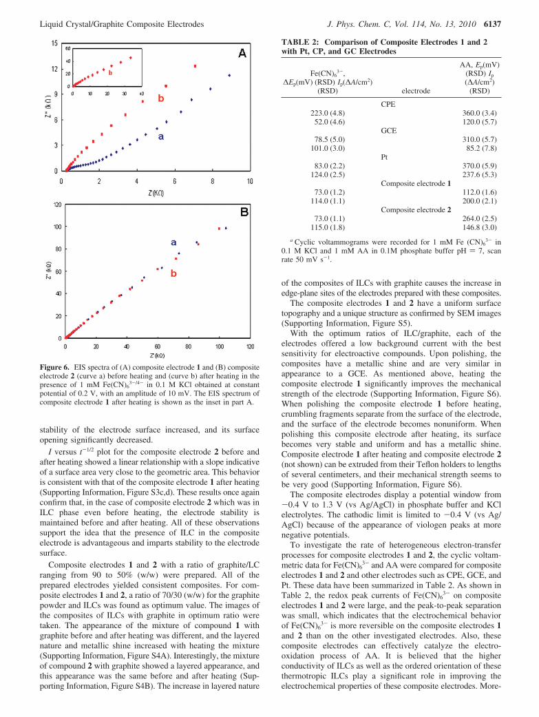
Electrochemical impedance spectroscopy (EIS) is a powerfultool for examining many chemical and physical processes insolutions as well as in solids. In order to clarify the differencebetween the electrochemical performance and surfaces of thecomposite electrodes 1 and 2 before and after heating, EIS wasused.
The electron-transfer kinetics of the redox probe at theelectrode interface is greatly influenced by electron-transferresistance.53 Figure 6 illustrates the results of impedancespectroscopy at composite electrodes 1 and 2 in the presenceof 1 mM Fe(CN)6
3-/4- as a diffusional redox probe in 0.1 MKCl obtained at the frequency range from 5 × 10⁻² to 1 × 10⁵
Hz at a constant potential of 0.2 V and an amplitude of 10 mV.Similar to the voltammetric signals, heating has a profoundeffect on the impedance responses obtained at compositeelectrode 1 but did not show any significant effect for compositeelectrode 2 (Figure 6). As shown in Figure 6A, the presence ofILC 1 as the binder in the composite electrode 1 significantlyaffects the surface impedance properties. A semicircle part inthe higher-frequency range is observed in the case of compositeelectrode 1 before heating, indicating a lower charge-transferrate at the electrode surface due to a relatively high electron-transfer resistance. The semicircular part corresponding to theelectron-transfer resistance at the electrode surface decreaseddramatically, and the impedance spectrum after heating the
electrode includes only the linear part so that the electron transferof the redox probe on this electrode surface has been greatlyfacilitated.
But as shown in Figure 6B, heating does not have anyappreciable effect on the impedance response of the electrodeprepared with compound 2 (which is LC at room temperature),and the impedance spectra include only the linear part beforeand after heating the electrode.
Chronoamperometry was also used to investigate the behaviorof the composite electrodes 1 and 2. Potential step wasperformed from 0 to 0.6 V by using the composite electrodesin 5 mM Fe(CN)6
3- in 0.1 M KCl to obtain a plot of I versust-1/2. A potential-step experiment performed at compositeelectrode 1 before heating results in a nonlinear I versus t-1/2
plot (Supporting Information, Figure S3a). The deviation fromCottrell behavior is attributed to the instability of the electrodesurface in aqueous solutions and extreme opening of the surfaceof the electrode resulting in alteration of charging current. Infact, the area of the electrode obtained in this case was muchlarger than the geometric area. The plot of I versus t-1/2 forcomposite electrode 1 after heating results in a linear relationship(Supporting Information, Figure S3b) with a slope indicativeof an effective surface area which approaches very closely thegeometric area of the electrode. These results show that, withthe transfer of compound 1 to ILC phase after heating, the
Figure 5. Cyclic voltammograms of (A) 1 mM Fe(CN)63- in 0.1 M
KCl and (B) 1 mM AA in buffer phosphate 0.1 M pH ) 7 on compositeelectrode 1 (curve a) before heating and (curve b) after heating andcomposite electrode 2 (curve c) before heating and (curve d) afterheating, scan rate 50 mVs-1. The i-E curves of curves b-d are shownas the inset in part A and B.
6136 J. Phys. Chem. C, Vol. 114, No. 13, 2010 Safavi and Tohidi
stability of the electrode surface increased, and its surfaceopening significantly decreased.
I versus t-1/2 plot for the composite electrode 2 before andafter heating showed a linear relationship with a slope indicativeof a surface area very close to the geometric area. This behavioris consistent with that of the composite electrode 1 after heating(Supporting Information, Figure S3c,d). These results once againconfirm that, in the case of composite electrode 2 which was inILC phase even before heating, the electrode stability ismaintained before and after heating. All of these observationssupport the idea that the presence of ILC in the compositeelectrode is advantageous and imparts stability to the electrodesurface.
Composite electrodes 1 and 2 with a ratio of graphite/LCranging from 90 to 50% (w/w) were prepared. All of theprepared electrodes yielded consistent composites. For com-posite electrodes 1 and 2, a ratio of 70/30 (w/w) for the graphitepowder and ILCs was found as optimum value. The images ofthe composites of ILCs with graphite in optimum ratio weretaken. The appearance of the mixture of compound 1 withgraphite before and after heating was different, and the layerednature and metallic shine increased with heating the mixture(Supporting Information, Figure S4A). Interestingly, the mixtureof compound 2 with graphite showed a layered appearance, andthis appearance was the same before and after heating (Sup-porting Information, Figure S4B). The increase in layered nature
of the composites of ILCs with graphite causes the increase inedge-plane sites of the electrodes prepared with these composites.
The composite electrodes 1 and 2 have a uniform surfacetopography and a unique structure as confirmed by SEM images(Supporting Information, Figure S5).
With the optimum ratios of ILC/graphite, each of theelectrodes offered a low background current with the bestsensitivity for electroactive compounds. Upon polishing, thecomposites have a metallic shine and are very similar inappearance to a GCE. As mentioned above, heating thecomposite electrode 1 significantly improves the mechanicalstrength of the electrode (Supporting Information, Figure S6).When polishing the composite electrode 1 before heating,crumbling fragments separate from the surface of the electrode,and the surface of the electrode becomes nonuniform. Whenpolishing this composite electrode after heating, its surfacebecomes very stable and uniform and has a metallic shine.Composite electrode 1 after heating and composite electrode 2(not shown) can be extruded from their Teflon holders to lengthsof several centimeters, and their mechanical strength seems tobe very good (Supporting Information, Figure S6).
The composite electrodes display a potential window from-0.4 V to 1.3 V (vs Ag/AgCl) in phosphate buffer and KClelectrolytes. The cathodic limit is limited to -0.4 V (vs Ag/AgCl) because of the appearance of viologen peaks at morenegative potentials.
To investigate the rate of heterogeneous electron-transferprocesses for composite electrodes 1 and 2, the cyclic voltam-metric data for Fe(CN)6
3- and AA were compared for compositeelectrodes 1 and 2 and other electrodes such as CPE, GCE, andPt. These data have been summarized in Table 2. As shown inTable 2, the redox peak currents of Fe(CN)6
3- on compositeelectrodes 1 and 2 were large, and the peak-to-peak separationwas small, which indicates that the electrochemical behaviorof Fe(CN)6
3- is more reversible on the composite electrodes 1and 2 than on the other investigated electrodes. Also, thesecomposite electrodes can effectively catalyze the electro-oxidation process of AA. It is believed that the higherconductivity of ILCs as well as the ordered orientation of thesethermotropic ILCs play a significant role in improving theelectrochemical properties of these composite electrodes. More-
Figure 6. EIS spectra of (A) composite electrode 1 and (B) compositeelectrode 2 (curve a) before heating and (curve b) after heating in thepresence of 1 mM Fe(CN)6
3-/4- in 0.1 M KCl obtained at constantpotential of 0.2 V, with an amplitude of 10 mV. The EIS spectrum ofcomposite electrode 1 after heating is shown as the inset in part A.
TABLE 2: Comparison of Composite Electrodes 1 and 2with Pt, CP, and GC Electrodes
Fe(CN)63-,
∆Ep(mV) (RSD) Ip(∆A/cm2)(RSD) electrode
AA, Ep(mV)(RSD) Ip
(∆A/cm2)(RSD)
CPE223.0 (4.8) 360.0 (3.4)52.0 (4.6) 120.0 (5.7)
GCE78.5 (5.0) 310.0 (5.7)
101.0 (3.0) 85.2 (7.8)Pt
83.0 (2.2) 370.0 (5.9)124.0 (2.5) 237.6 (5.3)
Composite electrode 173.0 (1.2) 112.0 (1.6)
114.0 (1.1) 200.0 (2.1)Composite electrode 2
73.0 (1.1) 264.0 (2.5)115.0 (1.8) 146.8 (3.0)
a Cyclic voltammograms were recorded for 1 mM Fe (CN)63- in
0.1 M KCl and 1 mM AA in 0.1M phosphate buffer pH ) 7, scanrate 50 mV s-1.
over, although the direct oxidation of AA at many commonelectrodes often suffers from pronounced fouling effect, theelectrode fouling of AA oxidation on composite electrodes 1and 2 is much less than that on common electrodes such asCPE, GCE, and Pt. As shown in Figure 7, contrary toconventional CPE, composite electrodes 1 and 2 show anattractive electrochemical behavior through stirring the solu-tion.40 In other words, oxidation of AA at the suggestedcomposite electrodes does not result in deactivation of theelectrode surface. This could be due to the presence of edge-
plane sites on the electrode surface which could impart anantifouling effect to the electrode surface.44,45
For further elucidation of the effect of ILCs on the propertiesof the resulting composite electrodes, some viologen compoundswith the same backbone structure and alkyl chain lengths ascompounds 1 and 2 but with different anions such as Br-, BF4
-,and PF6
- were synthesized. For a fixed alkyl chain length,considerable variability in thermal transitions is observed withalteration of the anions. In fact, the new compounds could notbe categorized as ILCs because the ILC phase transitions werenot observed for them, and some of them decompose prior toexhibiting a stable isotropic liquid phase.52 These compoundswere applied as binders for the preparation of the compositeelectrodes (dodecyl viologen dibromide salt in compositeelectrode 3, dodecyl viologen bis(tetrafluoroborate) salt incomposite electrode 4, dodecyl viologen bis(hexafluorophos-phate) salt in composite electrode 5, and Butyl viologenbis(hexafluorophosphate) salt in composite electrode 6). Dibro-mide and bis(tetrafluoroborate) salts of butyl viologen cannotbe used as binder because of their high solubility in water. Theelectrochemical responses of some of these composite electrodesare shown in Figure 8. A comparison between the cyclicvoltammetric data for Fe(CN)6
3- at these composite electrodesand composite electrodes 1 and 2 showed that the presenceof ILCs as the binder have promoting effect on the propertiesof the resulting electrodes and causes an increase in the rate ofelectron transfer and antifouling properties. These data have beensummarized in Table 3. From the results, it could be concludedthat implementing ILC as the binder can affect the morphologyof the electrode surface and increase the edge-plane sites in the
Figure 7. Cyclic voltammogram of 1 mM Fe(CN)63- in KCl 0.1 M
for consecutive scans (scan rate 50 mV/s) at (A) composite electrode1 (B) composite electrode 2, and (C) CPE. From cycle 3 for eachelectrode, the potential scan was held at starting potential and thesolution was stirred for 5 s, and then, scanning of potentials wascontinued after 20 s. Numbers on the graphs indicate cycle number.
Figure 8. Cyclic voltammograms of 1 mM Fe (CN)63- in 0.1 M KCl
for (curve a) composite electrode 1, (curve b) composite electrode 6,(curve c) composite electrode 2, (curve d) composite electrode 4, and(curve e) composite electrode 3, scan rate 50 mV s-1. The i-E curvesof curves a-d are shown as the inset.
a Cyclic voltammograms were recorded for 1 mM Fe (CN)63- in
0.1 M.
6138 J. Phys. Chem. C, Vol. 114, No. 13, 2010 Safavi and Tohidi
new composites which in turn offers an increasing of theelectrocatalytic activity as well as antifouling effect.44,45
The new composite electrodes can have potential applicationsin many direct electrochemistry, biosensors, and analysis ofbiocompounds. Figure 9 shows the applicability of the compositeelectrode 1 for simultaneous determination of dopamine,ascorbic acid, and uric acid and of the composite electrode 2for oxidation of H2O2.
Conclusions
In this work, thermotropic ILCs were used to fabricate carboncomposite electrodes. Improved sensitivity, electrocatalyticeffect, lower background current, antifouling properties, higherstability, reproducibility, high mechanical strength, low cost,simplicity of preparation, possibility of surface modification,and renewal are among the advantages of the suggested ILCcomposite electrodes. It is believed that the ordered orientationof the thermotropic ILCs can induce the formation of a highdensity of edge-plane-like defects. This could be in turnresponsible for imparting electrocatalytic activity as well asantifouling effect to the ILC composite electrodes. The ILCcomposite electrodes can have potential applications in manydirect electrochemistry, biosensors, and biocatalysis. The highstability of the surface of the electrodes makes them goodcandidates for use in flow systems.
Acknowledgment. The authors wish to thank the support ofthis work by Shiraz University Research Council and the ThirdWorld Academy of Sciences, Iran Chapter (TWASIC). Theauthors also thank Prof. Dr. Pradip K. Bhowmik for his usefulcomments on the synthesis of liquid crystals and Dr. M. M.Doroodmand and Miss F. Sedaghati for their help in obtainingimages.
Supporting Information Available: DSC thermograms andOPM images of compounds 1 and 2, chronoamperometricresponses of composite electrodes 1 and 2, photomicrographsof mixtures of compounds 1 and 2 with graphite, SEM imagesof the surface of composite electrodes 1 and 2, and photomi-crographs of composite electrode 1 before and after heating indifferent position. This material is available free of charge viathe Internet at http://pubs.acs.org.
References and Notes
(1) Liquid Crystals: The Fourth State of Matter; Saeva, F. D., Ed.;Marcel Dekker: New York, 1979.
(2) Binnemans, K. Chem. ReV. 2005, 105, 4148–4204.(3) Meier, G., Sackmann, E., Grabmaier, J. G. Applications of Liquid
Crystals; Springer Verlag: Berlin, 1995.(4) Belaidi, D.; Sebih, S.; Guermouche, M. H.; Bayle, J. P.; Boudah,
S. Chromatographia 2003, 57, 207–212.(5) Boudah, S.; Sebih, S.; Guermouche, M. H.; Rogalski, M.; Bayle,
J. P. Chromatographia 2003, 57 (Suppl.), S307–S311.(6) Judenstein, P.; Berdague, P.; Bayle, J. P.; Rogalska, E.; Rogalski,
M.; Petit-Jean, D.; Guermouche, M. H. J. Chromatogr. 1999, 859, 59–67.(7) Perez, F.; Berdague, P.; Courtieu, J.; Bayle, J. P.; Boudah, S.;
Guermouche, M. H. J. High. Resolut. Chromatogr. 1997, 20, 379–384.(8) Gritti, F.; Sourigues, S.; Felix, G; Achard, M. F.; Hardouin, F.
Chromatographia 2002, 55, 149–156.(9) Pesek, J. J.; Matyska, M. T.; Muley, S. Chromatographia 2000,
53, 439–444.(10) Ferroukhi, O.; Guermouche, S.; Guermouche, M. H.; Berdague,
P.; Bayle, J. P.; Lafontaine, E. Chromatographia 1998, 48, 823–829.(11) Saito, Y.; Ohta, H.; Nagashima, H.; Itoh, K.; Jinno, K.; Pesek, J. J.
J. Microcolumn Sep. 1995, 7, 41–49.(12) Pesek, J. J.; Matyska, M. T.; Bloomquist, T.; Carlon, G. J. Liq.
Chromatogr. Related Technol. 2005, 28, 3015–3024.(13) Matyska, M. T.; Pesek, J. J.; Katrekar, A. Anal. Chem. 1999, 71,
5508–5514.(14) Rill, R. L.; Liu, Y.; Van Winkle, D. H.; Locke, B. R. J. Chromatogr.
A. R.; Azadi, R.; Sedaghati, F. Chem. Commun. 2008, 6155–6157.(27) Safavi, A.; Abdollahi, H.; Maleki, N.; Zeinali, S. J. Colloid Interface
Sci. 2008, 322, 274–280.(28) Safavi, A.; Bagheri, M. J. Mater. Chem. 2007, 17, 1674–1681.(29) Electrochemical Aspects of Ionic Liquids; Ohno, H., Ed.; Wiley:
New York, 2005.(30) Ionic Liquids in Synthesis; Wasserscheid, P., Welton, T., Eds.;
Wiley-VCH: Weinheim, 2002.(31) Dupont, J.; de Souza, R. F.; Suarez, P. A. Z. Chem. ReV. 2002,
102, 3667–3692.
Figure 9. (A) Cyclic voltammogram of mixture of (curve a) 1 mMAA, (curve b) 1 mM dopamin, and (curve c) 1 mM uric acid inphosphate buffer 0.1 M pH ) 7.0 for composite electrode 1, scan rate100 mVs-1. The differential-pulse voltammogram of this mixture isshown in the inset. (B) Cyclic voltammogram of 4 mM H2O2 inphosphate buffer 0.1 M pH ) 7.0 for (curve a) composite electrode 2,(curve b) GCE, and (curve c) CPE, scan rate 50 mVs-1.