Design and characterization of microringreflectors with a waveguide crossing
Wei Shi,* Raha Vafaei, Miguel Ángel Guillén Torres, Nicolas A. F. Jaeger, and Lukas ChrostowskiDepartment of Electrical and Computer Engineering, University of British Columbia, Vancouver, British Columbia, Canada
Because of advantages such as easy fabrication, widetuning ranges, and easy monolithic integration with otherphotonic devices, waveguide microring-resonator wave-length-selective reflectors are of great interest as alterna-tives to Bragg gratings for a variety of applications, suchas tunable lasers, reflective filters, and sensors [1–4]. Re-flective sensors, functioning as reflective bandpass filters[1–3] or reflective notch filters [4,5], are particularly use-ful for harsh or special circumstances where a single in-put/output fiber is preferred [4]. Enabling more flexiblerouting, waveguide crossings are attractive for large-scale photonic integration. Here we present a novel mi-croring reflector employing a well-designed waveguidecrossing [6], which shows that low-loss, low-crosstalkwaveguide crossings, originally designed for complex in-tegrated photonic circuits, can be incorporated into mi-crocavity resonators to implement new functions. Havinga high extinction ratio and a high sensitivity, the pro-posed device can, potentially, be used as a reflectivenotch filter in optical-communication applications oras a thermal, biochemical, or other sensor.As shown in Fig. 1, the reflector consists of a dual-
coupler microring resonator that is “twisted” using awaveguide crossing to achieve reflection. We use thetransfer-matrix method [2] to analyze this device. Thefield components of the couplers are expressed as
Ei ¼ ½ ai bi ci di �T ; i ¼ 1; 2; 3; or 4: ð1Þ
The function of a directional coupler can be describedby a transfer matrix [2]:
C ¼ 1iκ
264
−τ 1 0 0−Tc τ 0 00 0 −τ 10 0 −Tc τ
375; ð2Þ
where κ ¼ jκje−ðiβþαÞLc and τ ¼ jτje−ðiβþαÞLc are the cou-pling coefficients, β is the propagation constant, α isthe loss coefficient, Lc is the coupling length, and Tc ¼jκj2 þ jτj2 is the total power transfer coefficient. The re-lation between the left port and the right port of the buswaveguide is given by
E1 ¼ C12P23C34E4: ð3Þ
C12 and C34 are the coupler transfer matrices. P23 is thetransfer matrix for propagation through the waveguidesections of lengths L1 and L2 and is given by
P23 ¼
264
0 0 0 PL1
0 0 P−1L2 0
0 PL2 0 0P−1L1 0 0 0
375; ð4Þ
where PL1ð2Þ ¼ te−ðiβþαÞL1ð2Þ , in which t is the transmissioncoefficient of the waveguide crossing. Assuming that theoptical signal is input from the left port, i.e., the incomingsignal Ein ¼ a1 and c4 ¼ 0, we can calculate the reflectedsignal Er ¼ d1 and the through signal Et ¼ b4 by usingEq. (3) with the following relationships:
a4 ¼ b1e−ðiβþαÞL3 ; d4 ¼ c1eðiβþαÞL3 : ð5Þ
The device is designed based on 500-nm-wide, 220-nm-high silicon-on-insulator nanowires, with a gap of 200 nmin the coupling regions and a waveguide bend radius of30 μm. Losses are an important factor for reliable designof microring-resonator reflectors [7]. A waveguide propa-gation loss α ¼ 5 dB=cm and a power transfer coefficient
Fig. 1. (Color online) SEM image of the device with the trans-fer-matrix elements labeled. The insets show details of thewaveguide crossing and the coupler.
of the couplers Tc ¼ 0:9, extracted in previous work [8],are used in our simulation. The waveguide crossing,using parabolically broadened waveguides and a double-etch scheme, is described in detail in [6]. An SEM imageof the crossing is shown in Fig. 1 (inset). It was simulatedusing the 3D finite-difference time-domain method with a5 nm mesh and predicted to have an insertion loss of 0.2dB and a crosstalk of −28 dB that is ignored in our ana-lytic model. The waveguide effective indices are calcu-lated by a two-dimensional finite-difference modesolver [9]. The coupling coefficients of the directionalcouplers are calculated using coupled-mode theory [10].
Coupling coefficients are critical to the performance ofmicroring resonators [2] and, as shown in Fig. 2, signifi-cantly affect the shape, magnitude, Q factor, and extinc-tion ratio of the reflection spectrum. Therefore, we use aracetrack shape to carefully control the coupling coeffi-cients. To find the optimal coupling condition, we scanthe reflection spectrum as a function of κ12 and κ34 andcalculate Rp − Rv and 10 logðRp=RvÞ, where Rp is the max-imum reflectivity and Rv is the minimum reflectivity.Based on the results shown in Fig. 3, we choose κ12 to
Fig. 2. (Color online) Simulated reflection spectra for severalcoupling conditions: (a) high reflectivity, high extinction ratio;(b) low reflectivity, high extinction ratio; (c) high reflectivity,low extinction ratio.
Fig. 3. (Color online) (a) Difference between the maximumreflectivity and the minimum reflectivity and (b) extinctionratio calculated as functions of the coupling coefficients.
Fig. 4. (Color online) Measurement schematic with an insetshowing an image of the Y-branch power splitter.
Fig. 5. (Color online) Measured and simulated reflection spec-tra at 25 °C (an estimated insertion loss of 38 dB is included inthe simulation; the optical paths are tuned to fit the free spectralrange and the resonance peaks).
be 0.84 and κ34 to be 0.77 in order to satisfy the dualcriteria of high reflectivity and high extinction ratio.The device was fabricated by ePIXfab at IMEC using
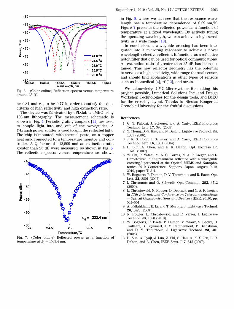
193 nm lithography. The measurement schematic isshown in Fig. 4. Periodic grating couplers [11] are usedto couple light into and out of the waveguides. AY-branch power splitter is used to split the reflected light.The chip is mounted, with thermal paste, on a copperheat sink connected to a temperature monitor and con-troller. A Q factor of ~12,500 and an extinction ratiogreater than 25 dB were measured, as shown in Fig. 5.The reflection spectra versus temperature are shown
in Fig. 6, where we can see that the resonance wave-length has a temperature dependence of 0:09 nm=K.Figure 7 presents the reflected power as a function oftemperature at a fixed wavelength. By actively tuningthe operating wavelength, we can achieve a high sensi-tivity in a wide range [10].
In conclusion, a waveguide crossing has been inte-grated into a microring resonator to achieve a novelwavelength-selective reflector. It functions as a reflectivenotch filter that can be used for optical communications.An extinction ratio of greater than 25 dB has been ob-tained. This new reflector geometry has the potentialto serve as a high-sensitivity, wide-range thermal sensor,and should find applications in other types of sensorssuch as biomedical [4], rf [12], and strain.
We acknowledge CMC Microsystems for making thisproject possible, Lumerical Solutions Inc. and DesignWorkshop Technologies for the design tools, and IMECfor the crossing layout. Thanks to Nicolas Rouger atGrenoble University for the fruitful discussions.
References
1. G. T. Paloczi, J. Scheuer, and A. Yariv, IEEE PhotonicsTechnol. Lett. 17, 390 (2005).
2. Y. Chung, D.-G. Kim, and N. Dagli, J. Lightwave Technol. 24,1865 (2006).
3. J. K. S. Poon, J. Scheuer, and A. Yariv, IEEE PhotonicsTechnol. Lett. 16, 1331 (2004).
4. H. Sun, A. Chen, and L. R. Dalton, Opt. Express 17,10731 (2009).
5. W. Shi, R. Vafaei, M. Á. G. Torres, N. A. F. Jaeger, and L.Chrostowski, “Ring-resonator reflector with a waveguidecrossing,” presented at the Optical MEMS and Nanopho-tonics 2010 Conference, Sapporo, Japan, August 9–12,2010, paper Tu3-4.
6. W. Bogaerts, P. Dumon, D. V. Thourhout, and R. Baets, Opt.Lett. 32, 2801 (2007).
7. I. Chremmos and O. Schwelb, Opt. Commun. 282, 3712(2009).
8. L. Chrostowski, N. Rouger, D. Deptuck, and N. A. F. Jaeger,in 17th International Conference on Telecommunications—Optical Communications and Devices (IEEE, 2010), pp.544–551.
9. A. Fallahkhair, K. Li, and T. Murphy, J. Lightwave Technol.26, 1423 (2008).
10. N. Rouger, L. Chrostowski, and R. Vafaei, J. LightwaveTechnol. 28, 1380 (2010).
11. W. Bogaerts, R. Baets, P. Dumon, V. Wiaux, S. Beckx, D.Taillaert, B. Luyssaert, J. V. Campenhout, P. Bienstman,and D. V. Thourhout, J. Lightwave Technol. 23, 401(2005).
12. H. Sun, A. Pyajt, J. Luo, Z. Shi, S. Hau, A. K.-Y. Jen, L. R.Dalton, and A. Chen, IEEE Sens. J. 7, 515 (2007).
Fig. 6. (Color online) Reflection spectra versus temperaturearound 25 °C.
Fig. 7. (Color online) Reflected power as a function oftemperature at λ0 ¼ 1533:4 nm.