© 2021 JETIR April 2021, Volume 8, Issue 4 www.jetir.org (ISSN-2349-5162)
JETIR2104234 Journal of Emerging Technologies and Innovative Research (JETIR) www.jetir.org 256
DESIGN AND COMPUTATIONAL ANALYSIS
OF CONCAVITIES EFFECT OVER
DIFFERENT WING PROFILE 1Gourav , 2Bhomesh Kumar Tamrakar , 3Saundarya Maharana , 4Bilji c Mathew
1,2,3Undergraduate Student, 4Research Supervisor
1,2,3,4Department of Aerospace Engineering,
1,2,3,4Lovely Professional University, Phagwara, India.
Abstract
The main objective of aircraft aerodynamics is to enhance the aerodynamic characteristics and maneuverability of the
aircraft. The airfoil which contains concavity/dimple will have comparatively less drag than the plain airfoil. Introducing
concavity on the aircraft wing will create turbulence by creating vortices which delays the boundary layer separation
resulting in decrease of pressure drag and also increase in the angle of stall. The dimpled airfoil has comparatively lesser
drag as compared to plain airfoil. Introducing concavity on the aircraft wing will create turbulence by creating vortices
which delay the boundary layer separation resulting in decrease of pressure drag and also increase in the angle of the
stall. In addition, wake reduction leads to reduction in acoustic emission. The objective is to improve the aircraft
maneuverability by delaying the flow separation point at stall and thereby reducing the drag by applying the dimple
effect over the aircraft wing. A computational analysis has done to know the dimple effect on three different types of
aircraft wing i.e. Rectangular Wing, Tapered Wing and Delta Wing, using NACA 2412 airfoil. Dimple shapes of square
inward is taken for the analysis; airfoil is examined at the inlet velocity of 250m/s and we are considering aircraft in
cruise state, hence we have taken the angle of attack 4˚ at cruise for all three wings. This analytical benefits the dimple
effect by increasing L/D ratio and thereby resulting the high aerodynamic efficiency, which upgrades the performance
of the aircraft.
Keywords: Dimple Effect, Square Dimple, Boundary Layer Separation, Lift and Drag.
Introduction
Aerodynamics is the study of forces and the resulting motion of objects through the air. Studying the motion
of air around an object allows us to measure the forces of lift, which allows an aircraft to overcome gravity, and
drag. Increasing the aerodynamic efficiency (L/D) is an essential parameter that specifies the performance of the
aircraft.
The boundary layer theory
The boundary layer is a very thin layer of air flowing over the surface of an aircraft wing, or airfoil. The molecules
heading to the surface of the wing are virtually stationary. Each layer of molecules within the boundary layer moves
faster than the layer that is closer to the surface of the wing. At the top of the boundary layer, the molecules move at the
same speed as the molecules outside the boundary layer. This speed is termed as the free-stream velocity. The fluid layer
at the edge of the solid surface has to counter surface friction at the expense of its kinetic energy and this loss in kinetic
energy is retrieved from the adjacent from the immediate fluid layer in contact with the layer adjacent to a solid surface
through momentum swap process and at some point the layer may not able to contact the surface and this point is called
point of separation. There are two types of boundary layers, i.e. laminar and the turbulent boundary layer. The laminar
boundary layer is a very smooth flow while the turbulent boundary layer contains swirls and eddies. The boundary layer
starts with the smooth laminar flow and then after some point it converted into turbulent boundary layer.
The flow separation occurs when the boundary layer travels against adverse far enough pressure gradient that the speed
of the boundary layer relative to the object drops almost to zero and the fluid separates from the surface of the object
and it leads to the formation of vortices. This result in increase in drag, especially pressure drag, which cause pressure
differential between the front and rear surfaces of the objects as it travels through air and this drag results in decreasing
aerodynamic efficiency and of manoeuvrability of an aircraft.
© 2021 JETIR April 2021, Volume 8, Issue 4 www.jetir.org (ISSN-2349-5162)
JETIR2104234 Journal of Emerging Technologies and Innovative Research (JETIR) www.jetir.org 257
Figure 1: Boundary Layer Separation
So the boundary layer is the main reason due to which the pressure drag increases and stall angle decreases on the wings
and hence some methods are adopted like vortex generator to delay the flow separation.
A vortex generator is a device which consists of a small vane, rectangular shaped, and placed over the surface of the
wing. It is used to produce vortex which helps in delay of the boundary layer separation. This vortex generator produces
their own vortices .These swirls of air energize the layer of air immediately above the wing’s surface and cause the air
to remain attached to the airfoil longer, as angle of attack increases.
Figure 2: Difference before and after Vortex Generators
The idea is inspired by golf ball theory. As golf ball has concavity on their surfaces, it helps to transform the flow from
laminar to turbulent which is produced due to the boundary layer. The turbulent boundary layer is able to remain stuck
to the surface of the ball much longer than a laminar boundary layer and so generates a narrow low pressure wake and
hence produces less pressure drag. Since the pressure drag reduces, the range of the ball increases.
© 2021 JETIR April 2021, Volume 8, Issue 4 www.jetir.org (ISSN-2349-5162)
JETIR2104234 Journal of Emerging Technologies and Innovative Research (JETIR) www.jetir.org 258
Figure 3: Flow visualization between Smooth Ball and Golf Ball
We can introduce this concept on the of the aircraft wing. On the wing, we construct the concavity at separate points
which works similar as the vortex generators. It will generate the turbulence which causes the delay in boundary layer
separation and hence reducing the pressure and increase in lift coefficient.
Research Methodology
In this research, the design is constructed in CATIA V5R20 and analysis is carried out using ANSYS 19.0. Lift and drag
coefficients are through computational analysis. Here we have done the analysis of three different types of wings i.e.
rectangular wing, tapered wing (Taper Ratio = 52%) and delta wing using NACA 2412 airfoil. The Specification of the
wing is given in the Table 1 below. Squared shapes are considered as cavities for the research work.
Wing Type Rectangular Wing Tapered Wing Delta Wing
NACA Series 2412 2412 2412
AOA (At Cruise State) 4° 4° 4°
Each Dimple Area(m2) 0.0625 0.0625 0.0625
No. of Concavity 39 47 28
Wing Area(m2) 5.8 5.8 5.8
Table 1: Specification of Wings
Below Figures shows rectangular wing, tapered wing and delta wing made by considering NACA-2412 airfoil which is imported
model from CATIA V5R20.
Figure 4: Rectangular Wing Figure 5: Tapered Wing
© 2021 JETIR April 2021, Volume 8, Issue 4 www.jetir.org (ISSN-2349-5162)
JETIR2104234 Journal of Emerging Technologies and Innovative Research (JETIR) www.jetir.org 259
Figure 6: Delta Wing
Analytical Results for Proposed Models The model of reference NACA 2412 airfoil wings with inward concavity is designed on the CATIA V5R20. Now they
are getting analysed in the ANSYS 19.0 Software. The parameters, analysis results and figures are shown below:
Table 2: Parameter Values
Parameter Values
Velocity 250 m/s
Angle of Attack 4o
Mach Number 0.847
Altitude 36000 ft. (or) 10972.8 m
Density 0.2981Kg/m3
Static Pressure 22.7 kPa
Dynamic Pressure 11.443 kPa
Total Pressure 36.435 kPa
Static Temperature 216.7 K
Total Temperature 248 K
Specific Heat Capacity at Constant Pressure (Cp) 1.0025
Specific Heat Capacity at Constant Volume (Cv) 0.7152
Dynamic Viscosity (µ) 1.329 x 10⁻⁵ Kg/m-s
Kinematic Viscosity (v) 3.7650 x 10⁻⁵ m2/s
Reynolds Number 664011
Speed of Sound 295.998 m/s
© 2021 JETIR April 2021, Volume 8, Issue 4 www.jetir.org (ISSN-2349-5162)
JETIR2104234 Journal of Emerging Technologies and Innovative Research (JETIR) www.jetir.org 260
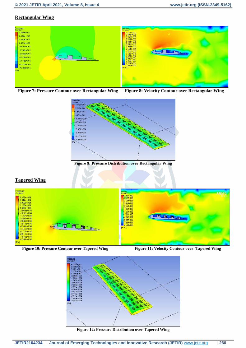
Rectangular Wing
Figure 7: Pressure Contour over Rectangular Wing Figure 8: Velocity Contour over Rectangular Wing
Figure 9: Pressure Distribution over Rectangular Wing
Tapered Wing
Figure 10: Pressure Contour over Tapered Wing Figure 11: Velocity Contour over Tapered Wing
Figure 12: Pressure Distribution over Tapered Wing
© 2021 JETIR April 2021, Volume 8, Issue 4 www.jetir.org (ISSN-2349-5162)
JETIR2104234 Journal of Emerging Technologies and Innovative Research (JETIR) www.jetir.org 261
Delta Wing
Figure 13: Pressure Contour over Delta Wing Figure 14: Velocity Contour over Delta Wing
Figure 15: Pressure Distribution over Delta Wing
3D ANALYSIS
All simulations of NACA 2412 i.g. Rectangular wing, Tapered wing, and Delta airfoil wing with square dimple
having 0.0625m² Area are carried out at the cruise state at angle of attack (AOA) 4⁰ and inlet velocity is taken
to be 250m/s. One of the objectives of this computational process is to increase the lift during a cruise flight.
The models are designed in CATIA V5R20 and computational study is done in ANSYS 19.0. And the
performance values determined by this study are given below in table:
Table 3: Performance Values
Formula used:
(i) Lift – to – Drag Ratio
R = CL / CD
(ii)Lift = L = ½ (CL x ρ x V2 x A)
(iii)Drag = D = ½ (CD x ρ x V2 x A)
Wing Type Rectangular Wing Tapered Wing Delta Wing
AOA (At Cruise State) 4o 4o 4o
L (N) 126038.03 101434.33 91592.19
D (N) 12892.11 12577.654 10814.144
CL 2.3 1.8 1.69
CD 0.24 0.23 0.20
L/D Ratio 9.5833 7.8261 8.45
© 2021 JETIR April 2021, Volume 8, Issue 4 www.jetir.org (ISSN-2349-5162)
JETIR2104234 Journal of Emerging Technologies and Innovative Research (JETIR) www.jetir.org 262
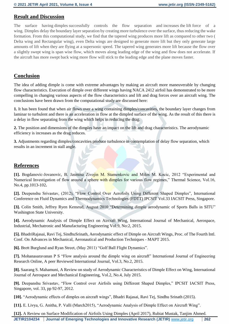
Result and Discussion
The surface having dimples successfully controls the flow separation and increases the lift force of a
wing. Dimples delay the boundary layer separation by creating more turbulence over the surface, thus reducing the wake
formation. From this computational study, we find that the tapered wing produces more lift as compared to other two (
Delta wing and Rectangular wing), even Delta wings are designed to generate more lift but they only generate large
amounts of lift when they are flying at a supersonic speed. The tapered wing generates more lift because the flow over
a slightly swept wing is span wise flow, which moves along leading edge of the wing and flow does not accelerate. If
the aircraft has more swept back wing more flow will stick to the leading edge and the plane moves faster.
Conclusion
The idea of adding dimple is come with extreme advantages by making an aircraft more maneuverable by changing
flow characteristics. Execution of dimple over different wings having NACA 2412 airfoil has demonstrated to be more
compelling in changing various aspects of the flow characteristics and lift and drag forces over an aircraft wing. The
conclusions have been drawn from the computational study are discussed here:
1. It has been found that when air flows over a wing containing dimples/concavities, the boundary layer changes from
laminar to turbulent and there is an acceleration in flow at the dimpled surface of the wing. As the result of this there is
a delay in flow separating from the wing which helps in reducing the drag.
2. The position and dimensions of the dimples have an impact on the lift and drag characteristics. The aerodynamic
efficiency is increases as the drag reduces.
3. Adjustments regarding dimples/concavities produce turbulence in contemplation of delay flow separation, which
results in an increment in stall angle.
References
[1]. Bogdanovic-Jovanovic, B. Jasmina Zivojin M. Stamenkovic and Milos M. Kocic, 2012 “Experimental and
Numerical Investigation of flow around a sphere with dimples for various flow regimes,” Thermal Science, Vol.16,
No.4, pp.1013-102.
[2]. Deepenshu Srivastav, (2012), “Flow Control Over Aerofoils Using Different Shaped Dimples”, International
Conference on Fluid Dynamics and Thermodynamics Technologies (FDTT) IPCSIT Vol.33 IACSIT Press, Singapore.
[3]. Colin Smith, Jeffrey Ryen Kensrud, August 2010 “Determining dimple aerodynamic of Sports Balls in SITU”
Washington State University.
[4]. Aerodynamic Analysis of Dimple Effect on Aircraft Wing, International Journal of Mechanical, Aerospace,
Industrial, Mechatronic and Manufacturing Engineering Vol:9, No:2, 2015.
[5]. BhadriRajasai, Ravi Tej, SindhuSrinath, Aerodynamic effect of Dimple on Aircraft Wings, Proc. of The Fourth Intl.
Conf. On Advances in Mechanical, Aeronautical and Production Techniques - MAPT 2015.
[6]. Brett Burglund and Ryan Street, (May 2011) “Golf Ball Flight Dynamics”.
[7]. Mohanasaravanan P S “Flow analysis around the dimple wing on aircraft” International Journal of Engineering
Research Online, A peer Reviewed International Journal, Vol.3, No.2, 2015.
[8]. Saarang S. Mahamuni, A Review on study of Aerodynamic Characteristics of Dimple Effect on Wing, International
Journal of Aerospace and Mechanical Engineering, Vol.2, No.4, July 2015.
[9]. Deepanshu Srivastav, “Flow Control over Airfoils using Different Shaped Dimples,” IPCSIT IACSIT Press,
Singapore, vol. 33, pp 92-97, 2012.
[10]. “Aerodynamic effects of dimples on aircraft wings”, Bhadri Rajasai, Ravi Tej, Sindhu Srinath (2015).
[11]. E. Livya, G. Anitha, P. Valli (March2015), “Aerodynamic Analysis of Dimple Effect on Aircraft Wing”.
[12]. A Review on Surface Modification of Airfoils Using Dimples (April 2017), Rubiat Mustak, Tanjim Ahmed.
© 2021 JETIR April 2021, Volume 8, Issue 4 www.jetir.org (ISSN-2349-5162)
JETIR2104234 Journal of Emerging Technologies and Innovative Research (JETIR) www.jetir.org 263
[13]. Thamodharan B, Shaik Mohamed Nagutha G,Sacraties A , Devaki P ,Numerical Analysis of Effect of Dimples on
Aero-dynamics of an Airfoil, International Conference on Explorations and Innovations in Engineering & Technology
(ICEIET - 2016).
[14]. K. Manojkumar1, P. Manivannan2, Eusebious T Chullai3 (April 2014), “Experimental Study - Flow
Characteristics of Dimpled Wing”.