56
Design and Construction of an Underwater Remotely Operated Vehicle Samantha Brody, Maila Sepri Swarthmore College Department of Engineering E90 Final Report 5 May 2005 1

Design and Construction of an Underwater Remotely Operated Vehicle
�
Samantha Brody, Maila Sepri
Swarthmore College Department of Engineering E90 Final Report
5 May 2005
1

Table of Contents: Page Part 1 A. Introduction and Background...……………………………………4-5
i. What are ROVs and AUVs? ii. Types of ROVs iii. Introduction to our project B. Design Goals and Decisions……………………………………….6-17 i. Frame/Structure, Waterproofing, and Tether a. Frame/Structure: Seafox Prototype and Modifications b. Frame/Structure: Propulsion System c. Frame/Structure: Camera d. Waterproofing e. Tether
ii. Electronics and Sensors a. Component Selection b. Overall Circuit/System Design c. PCB
iii. Joystick Interface and Navigation Module iv. PIC and Control Program
C. Experiments (What We Learned Along the Way)…………………17-20 i. Structural Component Trials ii. PIC Program Tests iii. Navigation Module Tests iv. Accelerometer and Gyroscope Tests D. Discussion……………………………………………………….…20-1 E. Acknowledgements………………………………………………...22
Appendix A: Component List with Prices…….…………..…………….…23-4 Appendix B: AWG and current carrying capacity for copper wire……...25 Appendix C: Electrical Component Data Sheets (Relevant Sections)........26-31 Appendix D: Multisim Schematic………………………………………..…32 Appendix E: Ultiboard Layout…………………………………………..…33 Appendix F: Nav Module Program……………………………………..….33-47 Appendix G: PIC Program………………………………………………....48-55 References…………………………………………………………………....56
2

Figures: 1: The Jason II ROV…………………………………………………………..…….….6 2: The Axis of Motion………………………………………………………….…….…6 3: Seafox Prototype…………………………………………………………….……….7 4: Bilge Pump……….………………………………………………………….……..…7 5a: Bilge Pump Layout (translation)…………………………………………………..8 5b. Bilge Pump Layout (rotation)……………………………………………………...8 6: Pulse Width Modulation………………………………………………………….…8 7: Overview of the Flow of Control of the ROV System………………………….….9 8: Picture of the Camera………………………………………………………….…....9 9: Diagram of the Camera……………………………………………………….....….10 10a: Waterproofed Power Box…..………………………………………………….…10 10b: Waterproof Box and Connectors, Opened……………………………….……..10 11: PIC18F4431 Microcontroller……………………………………………...……....12 12: MAX232 Chip……………………………………………………………….….…..12 13: MOSFET……………………………………………………………...………….....12 14: Gyroscope Evaluation Board .………………………………………………….....13 15: Accelerometer Evaluation Board…………………………………………….........13 16: Overall Design of the ROV System………………………………………….…....14 17: Transition from Breadboard to PCB……………………………………………..15
3

BACKGROUND AND INTRODUCTION: i. What are ROVs and AUVs? Underwater Remotely Operated Vehicles are a specific category of underwater robots that receive instructions from a human controller via a cable that remains attached to the robot at all times. The method of remote operation contrasts from autonomous operation, in which the robot itself is preprogrammed to assess particular aspects of the environment in which it is operating and to respond without the intervention of a human controller. There are advantages and disadvantages to both control techniques. The advantages of using an ROV are that complex manipulation can be done as necessary without increasingly complex code, and they are real-time controllable. AUVs, on the other hand, have greater flexibility with the spaces that they can explore since their motion is not limited by a cable. AUVs and ROVs are often used in a complementary manner where an AUV first surveys a site and determines an appropriate location for the deployment of an ROV. The applications of underwater ROVs include sub-sea infrastructure surveillance, inspection and some maintenance, military procedures, search and rescue missions, fish finding, and exploring and obtaining data about parts of the oceans where humans cannot go themselves.
ii. Types of ROVs While all ROVs have tethers linking them to a control center and almost all ROVs have thrusters, sensors, and cameras and/or hydrophones, the complexity and abilities of ROVs vary greatly. There are homemade ROVs of all levels constructed by individuals out of personal interest and curiosity and school projects (like ours). Such projects generally have lower budgets than the research and commercial ROVs funded by large companies and/or institutions. Mass-produced commercial ROVs can be subdivided into two categories: the “working” ROV and the “general” ROV. The working ROVs tend to be large, heavy and necessarily crew operated. They are used for tasks such as trenching, repair jobs, and recovery of heavy objects. General ROVs can be operated by fewer people and are often used for tasks such as ship inspections, search missions, and pipeline inspections. A third type of ROV is the research ROV, used for aiding in underwater scientific study. These are not necessarily different from commercial ROVs (which can be modified to incorporate specialized sensors), but their application is for research rather than search and rescue, maintenance, etc. One example of a research ROVs that is currently used for sea floor observation, imaging, sampling and precision sensing is the ROV system comprised of the ROV Medea and the ROV Jason II [4] (Figure 1). These were created by scientists at the Woods Hole Oceanographic Institution and can withstand pressure at depths up to 6500 meters. A neutrally buoyant cable connects the two ROVs to each other. Three copper conductors and three single-mode fiber optic cables allow for the remote control of the vehicles.
4

Figure 1. The Jason II ROV being lowered into the water (source: http://www.whoi.edu/marine/ndsf/vehicles/jason/index.html) iii. Introduction to our project The goal of our project is to design, construct and test an ROV that responds dependably to user commands. This task involves designing the physical structure of the ROV, its propulsion system, and its navigation system. We used the Seafox, a simple ROV whose designers published instructions for its construction [1], as a basis for our vehicle’s structure. Our project involves slight modifications to the Seafox’s physical configuration and great expansion upon its control unit. We have created control circuitry that operates the ROV’s bilge pump propulsion system and is compatible with a joystick command interface for real-time control. Our design allows the ROV to maneuver along 5 axes (forward, backward, right, left, pitch, and yaw – Figure 2)1. An on-board camera provides visual feedback from the ROV to aid in navigation and exploration, and sensors such as accelerometers and gyroscopes are included for use in localization. The ROV serves as a platform upon which other sensors and/or mechanical components can be mounted for further work in underwater environments.
Figure 2. The five axes over which the ROV has motion capabilities
� 1 The primary motivation for including the ability to pitch was to give the camera versatility in what it could view.
5

DESIGN AND DESIGN DECISIONS Our main goal is to design construct and test a remotely operated vehicle. This task can be subdivided into the sub-tasks listed below: i. Frame/Structure, Waterproofing and Tether
a. Frame/Structure: Seafox Prototype and Modifications We followed the instructions set out in Bohm and Jensen [1] for the frame construction and pump placement on a Seafox ROV in order to serve as an initial design upon which we could expand. The parts, prices, and manufacturers of the materials used, as well as those of the electrical components discussed later in this report, are tabulated in Appendix A.
Figure 3. A diagram of the Seafox from Bohm and Jensen’s book Even in the initial assembly, however, we made some changes to the suggested methods of construction. Instead of using two hollow PVC pipes with end caps as floatation device for the ROV, we placed foam and weights strategically around the ROV to ensure that the ROV would remain slightly positively buoyant. Bubble wrap was used for floatation around the top portion of the frame. This opened up space for the placement of a power box and an electronics box. The Seafox system is controlled using a toggle switch for each bilge pump. The operator of the ROV must decide which pump to turn on based upon his or her knowledge of the pump configuration and the desired direction of motion. We created control circuitry and programs for use with a joystick in order to simplify the user’s task in navigation. Adding an electronics box onboard the ROV was thus the predominant design modification that we made to the Seafox. It allowed us to reduce the number of wires connecting the ROV to the land-based controller and to create a more complex control system.
6

Another physical alteration we implemented was the addition of two additional pumps
als
back
ra
b. Frame/Structure: Propulsion System
n important part of the frame design and structural layout is the bilge pumps. The ROV
and consequently a rearrangement of the pump placement. Initial tests on the Seafox using a 7-conductor cable we created out of 16AWG wire in order to pass control signbetween land-based switches and the pumps indicated that more pumps were necessary to propel the ROV in the z direction (up and down). Two more pumps were ordered and placed in vertical orientation on the ROV. The pumps controlling motion in the z directions, which were originally placed in the center, were moved to the front and edges of the ROV. This option was implemented instead of immediately choosing to implement a ballast system for vertical motion and buoyancy control in the interest ofsimplicity and time. Some other changes that we implemented were addition of a cameto provide visual feedback, use of waterproof cable glands and addition RTV sealant to ensure sealing of the electronics boxes.
Asupports 8 Rule® 500 gallons per hour bilge pumps, which propel the vehicle by sucking water through a grid in their bases and expel it in a directed stream from a spout on the pumps’ sides (Figure 4).
Figure 4. Rule® 500GPH bilge pump
he placement of the pumps was determined in order to allow for all five desired modes
Tof motion. The pumps on the horizontal plane are oriented such that their spouts face at 45˚ angles from the horizontal. When the two shaded pumps in Figure 5.a are turned on, the vertical components of their forces cancel and the ROV translates towards the right. The pumps are offset slightly from the corners towards the central axis of the ROV. Thisgives the vehicle the capability to rotate when two pumps in opposite corners are turned on. The offset creates a couple on the body of the vehicle as shown in Figure 5.b. The up- and down- facing pumps use the same concepts to achieve z-axis translation and pitch.
7

(a) (b) Figure 5. Bilge pump layout on the ROV: (a) Translation (b) Couple that causes rotation The pumps nominally operate at 12V and draw 2.5 A to move 500GPH. However, the pumps are capable of operating at both higher and lower voltages. As the voltage is decreased the mass flow decreases, and conversely, as the voltage is increased the mass flow increases. Qualitative measurements as opposed to quantitative measurements were taken of this characteristic, but it would be useful to measure the actual change in mass flow and obtain a graphical representation of this pump feature. In order to establish multiple speed functionality for the ROV we wanted the pumps to operate at three states: (1) ON FAST, (2) ON SLOW, and (3) OFF. The middle speed is realized using pulse width modulation. Pulse width modulation (PWM) is a powerful technique for controlling analog circuits with a microprocessor's digital outputs. PWM is employed in a wide variety of applications, ranging from measurement and communications to power control. Pulse width modulation essentially works to create a middle speed by having the pumps pulse on and off at a set duty cycle. The duty cycle is given in terms of a percentage in which the pumps are in the on state. A diagram of three different duty cycles is illustrated in Figure 6. We chose to implement a 50% duty cycle for simplicity in programming.
Figure 6. A diagram of a 10%, a 50% and a 90% duty cycle to illustrate how pulse width modulation works. (source: http://www.embedded.com/story/OEG20010821S0096)
8
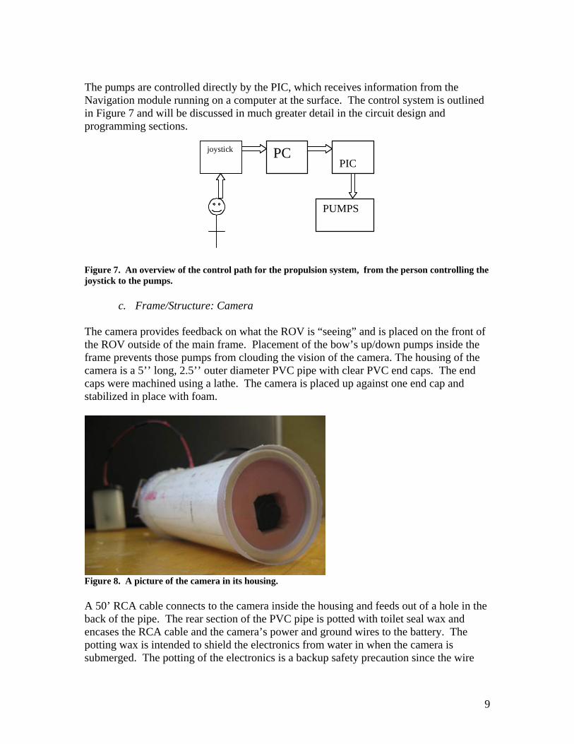
The pumps are controlled directly by the PIC, which receives information from the Navigation module running on a computer at the surface. The control system is outlined in Figure 7 and will be discussed in much greater detail in the circuit design and programming sections.
joystick PC
PIC
PUMPS
Figure 7. An overview of the control path for the propulsion system, from the person controlling the joystick to the pumps.
c. Frame/Structure: Camera
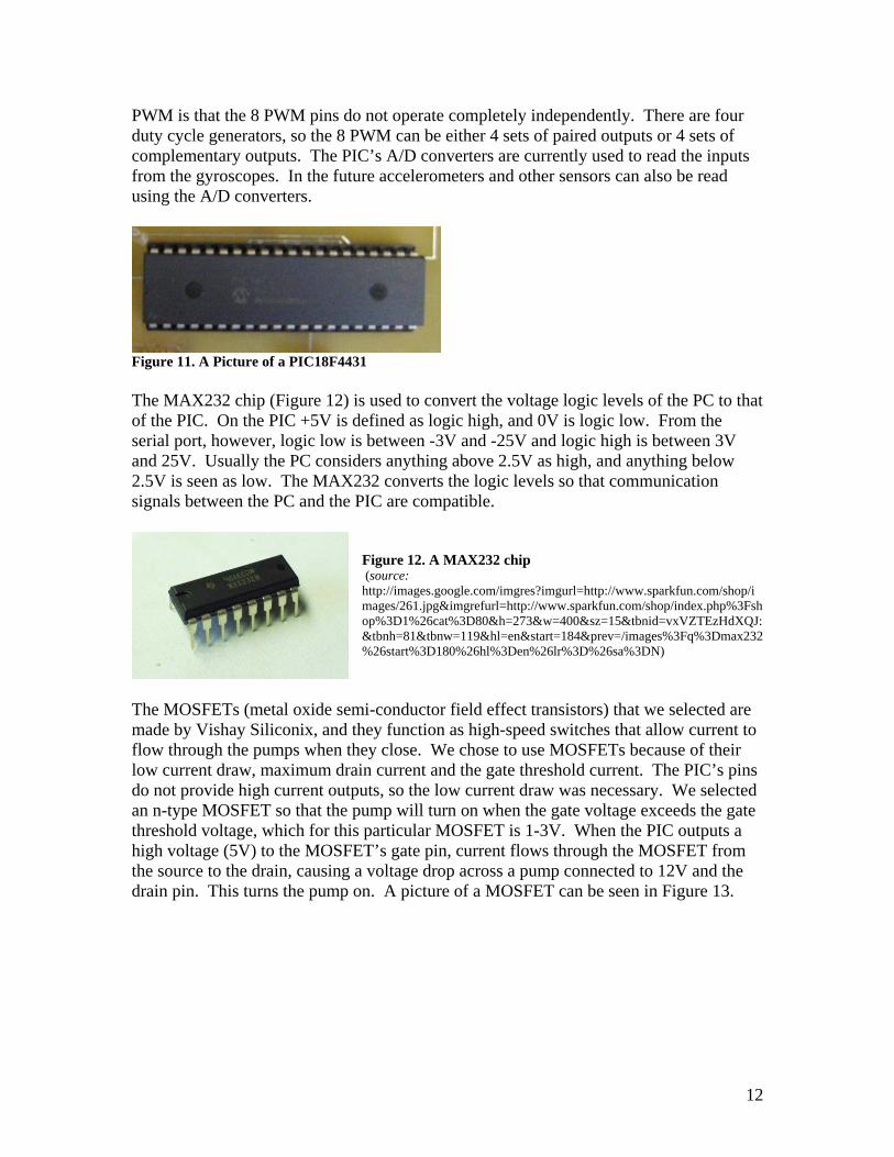
The camera provides feedback on what the ROV is “seeing” and is placed on the front of the ROV outside of the main frame. Placement of the bow’s up/down pumps inside the frame prevents those pumps from clouding the vision of the camera. The housing of the camera is a 5’’ long, 2.5’’ outer diameter PVC pipe with clear PVC end caps. The end caps were machined using a lathe. The camera is placed up against one end cap and stabilized in place with foam.
Figure 8. A picture of the camera in its housing. A 50’ RCA cable connects to the camera inside the housing and feeds out of a hole in the back of the pipe. The rear section of the PVC pipe is potted with toilet seal wax and encases the RCA cable and the camera’s power and ground wires to the battery. The potting wax is intended to shield the electronics from water in when the camera is submerged. The potting of the electronics is a backup safety precaution since the wire
9

hole and lens cap seams are coated with RTV sealant. The power and ground cables are fed into a film canister containing a 9V-battery. The separate housing for the battery provides for the ability to replace the battery without unsealing the PVC camera housing. Figure 8 is a photograph of the housing and camera described above, and Figure 9 depicts the components inside of the pipe and the RCA wire connectivity. RCA wires can be connected to a standard television monitor.
Figure 9. A diagram of the camera and housing.
d. Waterproofing
Waterproofing the electronics was a challenging and crucial task. The waterproofing of the camera is described above. The other components that needed to be waterproofed were the PCB and the power box. To do this we ordered project boxes of different sizes and drilled holes in the boxes to allow penetration of wires to make the appropriate connections. The wires were fed through Bud® waterproofing glands, and a coating of RTV sealant was applied around the seam between the connector glands and the box. A picture of the power box with the connectors and wires hooked up to a terminal strip can be seen in Figure 10.a, and an empty open project box are shown in Figure 10.b.
(a) (b)
Figure 10. Waterproof boxes with connector glands.
e. Tether
The cables that run down to the ROV to provide power and to control the pumps were an important part of the design process. The cables needed to be as light and flexible as possible to allow the ROV to move without being restricted by the cables. Initial tests
10

with our 7-conductor cable illustrated the effect of a heavy cable on a light vehicle as the ROV rotated and sank according to the position of the cable. For this reason we tried to minimize the weight and stiffness of the cable bundle fed to the ROV. The pump power cables had to be able to carry a maximum of 20A (8 pumps @ 2.5A max each) and to supply 12 volts. We also needed a cable for serial communication, a pair of smaller power supply wires for the microcontroller/sensor circuit components, and an RCA cable for the camera. By placing the power box as well as the PCB on the ROV itself we eliminated the need for numerous heavy cables, since power from a single pair of slightly larger power cables could be distributed to individual pumps onboard. The large power source was connected by the ROV by two 12AWG wires, one for power and one for ground. The serial communication was done across a 29AWG (AS165 Ultra Flexible Hookup Wire) wire made by Cooner Wire®. The power and ground for the PCB was also fed down a 29AWG Cooner Wire. Standard RCA cable was used for the video feedback. All 5 cables were cut to a length of 50ft to enable the ROV to move some distance away from the land-based computer. The chart that we used to determine the necessary gage of the wire can be found in Appendix B. ii. Electronics and Sensors
a. Component Selection
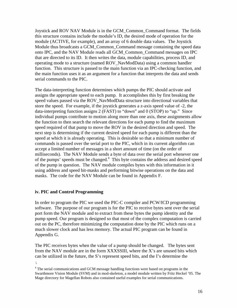
The major components on the control and sensor circuit are a PIC microcontroller, a MAX232 chip, 8 MOSFET transistors, a voltage regulator, and gyroscopes and accelerometers. We selected components with footprints that could be easily inserted and soldered into a PCB rather than surface mount components. All components are tabulated with their prices, manufacturers, and suppliers in Appendix A, and the pinouts from the components’ datasheets can be found in Appendix C. We initially chose Microchip’s PIC18F4431 microcontroller (Figure 10) for its 8 PWM outputs (4 complementary pairs), its 9 10-bit high-speed (up to 200K samples per second) A/D converters and its serial communication abilities. The PIC16F series is currently a commonly used family of microcontrollers, but they support only 2 PWM pins, so we chose the newer 18F series with 8 PWM outputs. In the final state of the project we did not end up using the built-in PWM modules; instead we used regular output pins and implemented manual PWM by alternating high and low outputs on the selected pin. There are two main reasons that we opted for the manual PWM. First, although we decided to use a relatively slow 4MHz resonator as the PIC’s clock, the minimum PWM pulse frequency possible was much higher than the pumps are able to respond to.2 The pumps’ motors carry some inductance, and so high-frequency pulses register simply as a lower mean voltage. Though the pumps can still function at a lower voltage, they are designed for use at 12V or higher, so we decided it would be better to use slow PWM rather than an intermediate voltage to achieve slow speeds. Another reason for manual � 2 The PIC’s PWM frequency is calculated using a formula given in the component’s data sheet. The variables in these calculations are the master clock frequency and values stored in data registers. Thus the PWM frequency is limited by the number of bits in each register.
11
PWM is that the 8 PWM pins do not operate completely independently. There are four duty cycle generators, so the 8 PWM can be either 4 sets of paired outputs or 4 sets of complementary outputs. The PIC’s A/D converters are currently used to read the inputs from the gyroscopes. In the future accelerometers and other sensors can also be read using the A/D converters.
Figure 11. A Picture of a PIC18F4431 The MAX232 chip (Figure 12) is used to convert the voltage logic levels of the PC to that of the PIC. On the PIC +5V is defined as logic high, and 0V is logic low. From the serial port, however, logic low is between -3V and -25V and logic high is between 3V and 25V. Usually the PC considers anything above 2.5V as high, and anything below 2.5V is seen as low. The MAX232 converts the logic levels so that communication signals between the PC and the PIC are compatible.
Figure 12. A MAX232 chip (source: http://images.google.com/imgres?imgurl=http://www.sparkfun.com/shop/images/261.jpg&imgrefurl=http://www.sparkfun.com/shop/index.php%3Fshop%3D1%26cat%3D80&h=273&w=400&sz=15&tbnid=vxVZTEzHdXQJ:&tbnh=81&tbnw=119&hl=en&start=184&prev=/images%3Fq%3Dmax232%26start%3D180%26hl%3Den%26lr%3D%26sa%3DN)
The MOSFETs (metal oxide semi-conductor field effect transistors) that we selected are made by Vishay Siliconix, and they function as high-speed switches that allow current to flow through the pumps when they close. We chose to use MOSFETs because of their low current draw, maximum drain current and the gate threshold current. The PIC’s pins do not provide high current outputs, so the low current draw was necessary. We selected an n-type MOSFET so that the pump will turn on when the gate voltage exceeds the gate threshold voltage, which for this particular MOSFET is 1-3V. When the PIC outputs a high voltage (5V) to the MOSFET’s gate pin, current flows through the MOSFET from the source to the drain, causing a voltage drop across a pump connected to 12V and the drain pin. This turns the pump on. A picture of a MOSFET can be seen in Figure 13.
12

Figure 13. Vishay/Siliconix MOSFET The Fairchild Semiconductor LM7805ct voltage regulator is used to send a smooth power signal to the electronics on the PCB. If 5V were sent through the 50ft 29AWG wire to the circuit board, some of the input power would be dissipated and the voltage would drop. This would prevent the components from receiving sufficient power to operate. The voltage regulator allows us to supply excess voltage levels to the circuit board and to down-regulate the voltage to a smooth 5V signal. Obtaining a smooth signal is important to reducing noise in sensors and for correct operation of the microcontroller. The gyroscopes are sensors that feed back rate of rotation. In order to obtain an absolute heading from the sensor an integration program must be implemented.3 The sensitivity of the ADXRS401 gyroscopes that we selected is ±75°/sec. The ROV does not move very quickly, so the gyroscope must be sensitive enough to detect the motion of the ROV and be able to feedback useful information. The gyroscopes also feed back the temperature to correct for drift over time. We ordered gyroscope evaluation boards (Figure 14) for ease of integrating into our circuit, since the individual components have small surface mount footprints and require external capacitors.
Figure 14. ADXRS401 gyroscope evaluation board. An accelerometer is a device for measuring acceleration and the effects of gravity, and their signals can be used to track the motion of the vehicle over time. The ADXL203 dual-axis accelerometers provide signals proportional to the acceleration of the ROV. This signal can be integrated to determine information about the velocity and the distance of the ROV. This is important in localizing the robot within a known space. As in the case of the gyros, we ordered the accelerometers’ evaluation boards (Figure 15) for easier implementation.
� 3 The gyroscopes and accelerometers are not yet completely incorporated onto the ROV. They have been tested and preliminary code has been written for obtaining useful readings from them, but the programs are not fully developed.
13

Figure 15. A picture of the accelerometer evaluation board.
b. Overall Circuit/System Design
The circuit containing all of the components listed above was printed on a PCB that is mounted on the ROV and connected to a PC through an RS232 interface. The PC, joystick, and joystick operator, as well as a large power supply for the pumps and a small power supply for the circuitry, are on land. In the water is the ROV and therefore the pumps, a waterproof power box which distributes the power to individual pumps from the large source, and another waterproof box which contains the PCB. The camera is also on the ROV. A diagram which shows this overall layout of the system can be found in Figure 16.
Figure 16. An overall view of the entire ROV system. That which is enclosed in the dotted line is underwater while everything outside the dotted line is on land.
c. The Printed Circuit Board The PCB which is enclosed in a waterproof box is an integral part of the ROV system. When we initially set up the circuit, we connected it on land on a breadboard. While this method worked and allowed us to fine-tune our circuit design, it also had many drawbacks. The major problem was that the electronics had to be on land, and consequently many cables went from the breadboard to the ROV. These cables included
14

16 16AWG wires (two for each pump). The cables coming up from the ROV were so thick and inflexible that they impeded the motion of the ROV. Another problem was that there were so many wires on the breadboard that when the wires were attached to a moving ROV they were easily pulled out of place. Once the PCB was manufactured and populated, and the electronics box (the project box which housed the PCB) was waterproofed, we were able to place the PCB in the electronics box on the ROV and eliminate the large restrictive wires. Figure 17 shows the transition of the circuit from a breadboard to the PCB.
Figure 17. These pictures show the transition fro the breadboard circuit to the PCB. The software that we used to design our PCB schematic and the circuit diagrams were Multisim7 and Ultiboard7. We sent these diagrams to Alberta Printed Circuits for board manufacturing. The Multisim schematic can be found in Appendix D and the Ultiboard layout can be found in Appendix E. Additional components such as capacitors, diodes, and resistors were added in the Multisim and Ultiboard layouts where necessary.
iii. Joystick Interface and Navigation Module The ROV is designed to be steered by an operator using a joystick, and its navigation module is programmed to be compatible with the same joystick command module written for the Swarthmore College Flying Robot [3] and wheeled Magellan and Nomad robots. This joystick command module is part of the Robomon library developed by Nicolas Ward ’05. The module is interfaced with a Logitech® WingmanExtreme joystick, which supports multiple sets of buttons so that z-axis translation and pitch can be controlled while x- and y- axis translation and yaw are controlled with the stick. The joystick module reads five analog signals (one corresponding to the position of the joystick along each axis of motion). It then converts the analog value to a digital value and assigns the digital value to one of five speed bins: -FAST, -SLOW, STOP, +SLOW, or +FAST. The negative speeds correspond to the backwards, left, and downward directions, as well as leftward turning and bow-down pitching. The positive speeds correspond to the forward, right, and upwards directions, plus right turning and bow-up pitching. The speed value for each axis is then stored in an array of doubles to be sent to the Navigation Module. The Joystick and Navigation Modules communicate using a version of Carnegie Mellon University’s Inter-Process Communication (IPC). Fritz Heckel ’05 used IPC as the foundation of the Swarthmore General Communication Module (GCM). GCM defines structures for passing messages between modules. The message passed between the
15
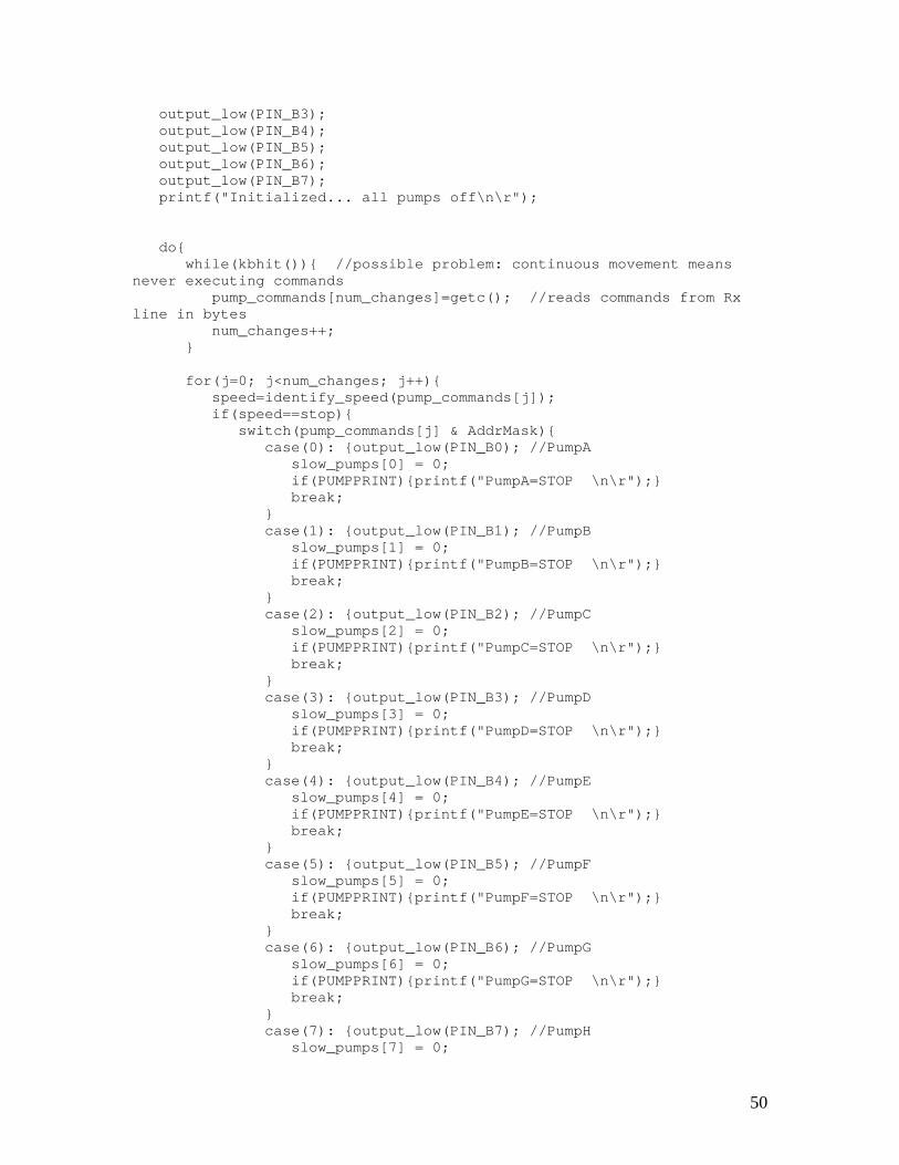
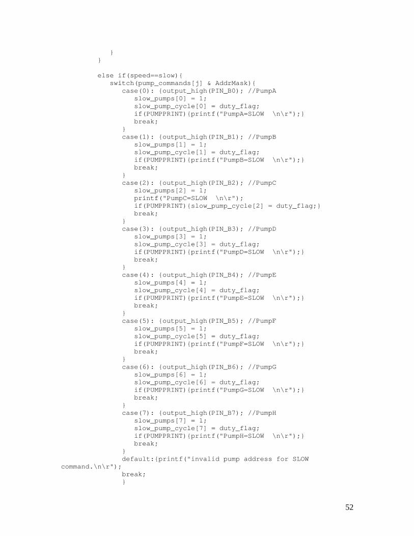
Joystick and ROV NAV Module is in the GCM_Common_Command format. The fields this structure contains include the module’s ID, the desired mode of operation for the module (ACTIVE, for example), and an array of 6 double data values. The Joystick Module thus broadcasts a GCM_Common_Command message containing the speed data onto IPC, and the NAV Module reads all GCM_Common_Command messages on IPC that are directed to its ID. It then writes the data, module capabilities, process ID, and operating mode to a structure (named ROV_NavModData) using a common handler function. This structure is passed to the main function via an IPC-checking function, and the main function uses it as an argument for a function that interprets the data and sends serial commands to the PIC. The data-interpreting function determines which pumps the PIC should activate and assigns the appropriate speed to each pump. It accomplishes this by first breaking the speed values passed via the ROV_NavModData structure into directional variables that store the speed. For example, if the joystick generates a z-axis speed value of -2, the data-interpreting function assigns 2 (FAST) to “down” and 0 (STOP) to “up.” Since individual pumps contribute to motion along more than one axis, these assignments allow the function to then search the relevant directions for each pump to find the maximum speed required of that pump to move the ROV in the desired direction and speed. The next step is determining if the current desired speed for each pump is different than the speed at which it is already operating. This is desirable so that a minimum number of commands is passed over the serial port to the PIC, which in its current algorithm can accept a limited number of messages in a short amount of time (on the order of milliseconds). The NAV Module sends a byte of data over the serial port whenever one of the pumps’ speeds must be changed.4 This byte contains the address and desired speed of the pump in question. The NAV module compiles bytes with this information in it using address and speed bit-masks and performing bitwise operations on the data and masks. The code for the NAV Module can be found in Appendix F. iv. PIC and Control Programming In order to program the PIC we used the PIC-C compiler and PCW/ICD programming software. The purpose of our program is for the PIC to receive bytes sent over the serial port form the NAV module and to extract from these bytes the pump identity and the pump speed. Our program is designed so that most of the complex computation is carried out on the PC, therefore minimizing the computation done by the PIC which runs on a much slower clock and has less memory. The actual PIC program can be found in Appendix G. The PIC receives bytes when the value of a pump should be changed. The bytes sent from the NAV module are in the form XXXSSIII, where the X’s are unused bits which can be utilized in the future, the S’s represent speed bits, and the I’s determine the
� 4 The serial communications and GCM message handling functions were based on programs in the Swarthmore Vision Module (SVM) and in mod-skeleton, a model module written by Fritz Heckel ’05. The Mage directory for Magellan Robots also contained useful examples for serial communications.
16

address of the pump that needs to be changed. Since there are three possible speeds (on, off, and slow) there are two speed bits, and since there are eight pumps, three identity bits are needed. The program works by checking the serial line, and if there is data waiting, the PIC reads in the bytes. Once there is nothing on the serial line, the program begins to execute by deciphering each byte and outputting the appropriate logic level to the pump identified in each byte. If the pump is to be turned on the logic level output of the appropriate pin should be high, and vice verse for off. In order to achieve the slow speed the PIC sends out alternating high and low signals every of 500ms. A flag is set high when the speed is determined to be slow. If the speed is slow and the duty flag is high the output is set high, and then after 500 ms the program checks to see if the speed is still slow and the duty flag set high. If this is the case the outputs are low for 500ms and the flag is set low. This process repeats, creating an alternating high and low cycle every 500 ms. C. EXPERIMENTS (What We Learned Along the Way)
The development process involved multiple tests of preliminary designs and partial components of the final system. The tests conducted on both the physical layout and on predecessors of the final code are detailed in the following sections. i. Structural Component Trials To test our SeaFox prototype, we assembled a 7-conductor, 16AWG cable by threading 10-foot-long wires through clear heat shrink tubing and sealing them together. We tested the ROV’s 6 bilge pumps by inserting their ground lead wires into the waterproofing glands that we screwed into one of the project boxes. Then we inserted the ground wire from the cable into the same box and connected them all on a terminal strip such that a star-configuration node was created. In the power project box we connected each of the 6 remaining wires from the cable to a power lead wire from one of the pumps. We screwed the boxes closed and attached the topside ends of the cable to switches powered by a 30A power source. This allowed us to manually turn on each pump and to test the system’s movement. This test revealed to us that one pump would not be sufficient to propel the ROV along the z-axis, so we decided to add 2 more vertically-facing pumps to our design We also discovered that the bilge pumps do not draw a full 2.5A (their max current rating) at 12V. Since they drew only 1.9A, we could operate the pumps at a higher power to achieve greater mass flow. The test also exposed shortcomings in our waterproofing methods. Although undetected until we re-opened the project boxes, they had totally filled with water. Luckily, this did not affect the pumps’ performance, but it became clear that simple gasket tightening
17

would not be sufficient. Consequently, we removed the rubber gaskets from the glands and added a lining of RTV silicone sealant around any penetrations of our project boxes. In preparing the pumps for the final sea trials, we also ran tests which powered the pumps through MOSFETs located on a breadboard. The MOSFETs replaced the switches and the pumps were connected to individual power supplies. The pumps were then turned ton and off according to the voltage level of the gate pin on the MOSFET. The pump/MOSFET combination operated as expected. ii. PIC Programming Tests In order to program the PIC and test code we had to set up a circuit for interfacing the 40-pn PIC with an RJ12 serial cable socket using the wiring instructions on the CCS FAQ webpage [2]. The first step in developing PIC programs was to test the microcontroller’s output pins with a simple control signal. We wrote an Analog-to-Digital conversion display function that read an analog signal from the PIC’s ADC pins (PortA) and put out the 8-bit digital value on the PortB pins. We then displayed this value on the 8 LEDs on the breadboard and verified that the ADC and outputs worked by feeding square and sine waves into the ADC pins and watching the output vary on the LEDs. Next we wrote a program to control the output of a single pin based on a command received serially. This involved development of the bit masks used in the final code and connecting the PIC’s Rx and Tx lines to those of the computer’s serial port. For this we inserted breadboard wires into the female connector of a DB9 null modem cable.5 Like the final program, this test program accepted bytes over the serial port, and we used HyperTerminal to send individual characters for testing the code. We determined the ASCII binary values of keyboard characters and observed the output based on our knowledge of the individual bits that HyperTerminal transmitted. In this way we were able to output the stop, slow (square wave), and fast speed commands on the LEDs. This test revealed to us the necessity of using a MAX232 chip to convert the computer’s logic levels to the PIC’s logic levels. In the third test, the code was expanded to accommodate 8 pumps. Our manual PWM code was modified in this step because the preliminary design did not set the slow speed pumps’ output values at every pass through the loop. Therefore, when a pump was assigned a slow speed, it was either turned on or off, but the value did not alternate. The new design alternated the signal between high and low, creating a slow speed. Once this was completed the PIC was ready to accept commands for changing pumps’ speeds form the NAV Module.
� 5 Pin 2 on the cable is the PC’s Tx and therefore connects to the PIC18F4431’s Rx pin 26, and pin 3 on the null modem is the PC’s Rx, which connects to the PIC’s Tx pin 27. The cable’s ground pin, 5, was also tied to the breadboard ground.
18
iii. Navigation Module Tests Since the NAV Module accepts IPC messages and sends commands over the serial port, the primary tests conducted upon it dealt with these capabilities. Its pump and speed assignment code was tested with the standard print-statement fashion. In order to test the message-reading capabilities without the joystick command module, we wrote a program to generate GCM_Common_Command messages with data values entered from the command line. When this program is run, five speed commands in the range [-2, 2] must be entered. The order of the speed commands is: y-, yaw, z-, pitch, and x-, as specified in the header file for GCM IPC messaging.6 Passing values with this program allowed us to print speed values as the program ran to verify that the pump assignment worked correctly. We used a serial test program to debug our program’s ability to write to the serial port. The test program writes command line- characters to the serial port, and we initially tested it by connecting a null modem cable from the computer running the NAV module to another computer running HyperTerminal. When those characters successfully transmitted, we tested our NAV module’s address- and speed-mask compilation by pasting the same byte-generation code into the serial test program and printing the hex value. Next the code was incorporated into the NAV module, and the hex values of the commands to the PIC were displayed in HyperTerminal. Finally the null modem cable was connected to the PIC on a breadboard, and LEDs were used to evaluate the pump command performance. During the NAV module test we encountered problems with the PIC not responding to commands fed to it in rapid succession. This problem was dealt with by adding a 1000ms delay into the loop that sends the pump commands. iv. Accelerometer and Gyroscope Testing We connected the accelerometer and gyroscope evaluation boards to a breadboard circuit and then moved the breadboard at approximately the translation speed of the ROV. This was done to ensure that the accelerometer was sensitive enough to output a change in voltage at speeds similar to the ROV speed. The ADXL203 accelerometers did output a changing voltage in response to the movement of the breadboard, so they will be useful in determining the acceleration of the ROV and the distance traveled by the ROV. Similar test were done with the gyroscopes. The circuit was set up on a breadboard and the breadboard was rotated at rotation speeds similar to those exhibited by the ROV. The
� 6 A note on running “manualCommand” for testing IPC messaging to the NAV Module: Three terminals in the localhost’s directory must be open, and the localhost computer must be configured for IPC. One terminal must run “central”, another must run “bin./ROV_NavMod”, and the other must run “bin/manualCommand ROV_JOYSTICK y yaw z p x”, where the axis values are speeds between –2 and 2.
19

voltage output of the gyroscope did change in response to the rotating breadboard, so it will be useful and informative when integrated into the control circuit of the ROV. The PIC program contains an integration routine with a 10-bit A/D converter. Data collection begins one pump duty cycle after power is turned on since turning on the power causes a voltage jump. A pump duty cycle’s data is averaged for calibration. Currently the duty cycle is set to 500ms, and the gyroscope data is sampled every 5ms, averaging 100 data points. This value is then subtracted from the current voltage along with 255 (the binary equivalent of 2.5 volts -- the "zero" of the sensor). After this initial calibration calculation, data is integrated integrates continuously, sampling every 5ms. In order to calibrate the gyroscope, first a 10ms sample time was used. At that point the integration in volts was essentially equal to the degrees rotated. However, if the board was turned too quickly, the output voltage was no longer accurate. In order to avoid this, the sampling frequency was increased to 5ms. At this point, calibration was done by trial and error. The board was turned 90°, and the voltage output was noted and then converted to degrees. The final conversion factor was .687 degrees/volt. This is not the best method of obtaining the rate of rotation because the integration may depend on the speed of the code. The gyroscope also contains a temperature sensor which is necessary to calibrate the output of the gyroscope since it has a tendency to drift with temperature. The temperature output can also serve as an additional sensor. The datasheet for the gyroscope provides some of the specs for the conversion of voltage to temperature. The sensor nominally outputs 2.5 volts at 27°C and the conversion is 8.4 mV/°C. DISCUSSION Our final ROV has achieved control about five axes of motion with all of the electronics submerged and a working joystick interface. The NAV Module readily accepts GCM_Common_Command messages and is therefore completely capable of reading commands sent from a joystick module. An initial obstacle that we faced in serial communications between the NAV Module and the PIC was allowing for sufficient time for the PIC to accept and store one byte of data before the next byte appeared on the line. This bug was overcome, however, and now both the programs on the PIC and on the PC work well. These programs allow for basic operations, and there is room to modify them if additional sensors or functionality are desired. At this point the basic ROV is functional, but there are many improvements that can be made to increase the capabilities of the ROV. One important improvement that can be made is the integration of a ballast system so that the ROV can have more control over its buoyancy and stability. Currently a combination of floats and weights are placed strategically on the ROV to balance out the weight distribution and to strive for neutral buoyancy. This method is not long-term or reliable, and any changes that are made to the ROV will quickly offset this precarious method of achieving neutral buoyancy and balance. Another improvement upon the vehicle’s stability would be adding floatation
20

devices to the tether to ensure that the cable’s weight does not interfere with the ROV’s motion. There are also some of the aspects of the programming that can be changed to make the ROV code a little more efficient and to increase the number of possible speeds of the ROV. An interrupt handler can be utilized as data is sent from the Nav module, and variable PWM can allow for greater speed control. As of now, the PIC program responds to data being put on the serial line, and therefore is constantly checking the serial port to see if any pumps have changed. An alternate way of implementing code that responds to data being sent over the serial line is to make an interrupt handler to deal with the pumps that need to be changed. This way the program will run in its current state until an interrupt is detected. Once the interrupt is recognized a subprogram will run to determine the identity of the pump and the new speed. Once the appropriate pumps are change the ROV will return to its main program until another interrupt is received. Variable PWM is another change that could be implemented in the code to the ROV to achieve a greater number of possible speeds. Currently the PWM operates only on a 50% duty cycle allowing for one intermediate speed. One improvement that is already underway is the addition of a navigation system to determine how fast the ROV is rotating, its acceleration, and distance traveled. Once this feedback can be obtained a higher degree of control can be asserted over the ROV. For example, a command such as “move forward three feet”—as opposed to now when we can just say “move forward”—will be possible. The beginning of a program to implement the gyroscope is already present in the PIC program. This information can also be sent back to a PC where the ROV’s motion can be simulated, so if the ROV travels out of sight, some visual reference will still remain available. Another major improvement that can be made is the implementation of a more efficient propulsion system. While the bilge pumps are simple, reliable and get the job done, they are not primarily designed to function as elements in a propulsion system. Thrusters with propellers designed specifically for maximizing propulsion may offer stronger and more efficient propulsion through the water. Additional sensors, such as salinity sensors, depth and pressure sensors, water samplers and any other instruments that can be used to gather information can be integrated into the existing system. Additional capabilities such as a manipulator arm will also increase the dexterity of the ROV. The physical structure of our ROV can also be improved, and although ROVs are not necessarily sleek there are definitely ways of improving the hydrodynamic quality of the frame. As a result of the strong foundation that resulted from this project, there are many directions in which this project can go.
21

ACKNOWLEDGEMENTS Our project would not have been possible without the advice, help and time of various people. First and foremost we would like to recognize Alexey Rostapshov ’05 for his hard work on the programming and construction of the ROV and for his help in developing our presentations. Bruce Maxwell, our main advisor, kept us on track and moving forward while providing new design ideas and alternate implementation methods for various tasks throughout the entire process. Other professors, including Carr Everbach, Fred Orthlieb, and Erik Cheever also provided assistance on various parts of the design and construction. Grant Smith helped with the machining and the physical construction of the ROV. Ed Jaoudi helped us in figuring out what parts we needed, what parts we had, where to order the parts from, obtaining and installing the necessary software, and much more. Fellow students Nick Ward and Fritz Heckel are working with us and allowing us to use and modify their previously written code to interface the joystick with the control of the ROV.
22
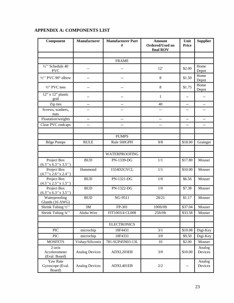
APPENDIX A: COMPONENTS LIST
Component Manufacturer Manufacturer Part #
Amount Ordered/Used on
final ROV
Unit Price
Supplier
FRAME
½’’ Schedule 40 PVC -- -- 12’ $2.00 Home
Depot
½’’ PVC 90° elbow -- -- 8 $1.50 Home Depot
½” PVC tees -- -- 8 $1.75 Home Depot
12” x 12” plastic grid -- -- 1 -- --
Zip ties -- -- 40 -- -- Screws, washers,
nuts -- -- -- -- --
Floatation/weights -- -- -- -- -- Clear PVC endcaps -- -- -- -- -- PUMPS
Bilge Pumps RULE Rule 500GPH 9/8 $18.00 Grainger WATERPROOFING
Project Box (6.3’’x 6.3‘’x 3.5’’)
BUD PN-1339-DG 1/1 $17.80 Mouser
Project Box (4.7’’x 2.6‘’x 2.4’’)
Hammond 1554D2GYCL 1/1 $10.00 Mouser
Project Box (4.5’’x 2.5‘’x 1.5’’)
BUD PN-1321-DG 1/0 $6.56 Mouser
Project Box (6.3’’x 6.3‘’x 3.5’’)
BUD PN-1322-DG 1/0 $7.38 Mouser
Waterproofing Glands (16 AWG)
BUD NG-9511 28/21 $1.17 Mouser
Shrink Tubing ½’’ 3M FP-301 100ft/0ft $37.04 Mouser Shrink Tubing ¾’’ Aloha Wire FIT1003/4 CL008 25ft/0ft $33.58 Mouser
ELECTRONICS
PIC microchip 18F4431 3/1 $10.08 Digi-Key PIC microchip 18F4331 3/0 $9.50 Digi-Key
MOSFETS Vishay/Siliconix 781-SUP45N03-13L 10 $2.00 Mouser 2-axis
Accelerometer (Eval. Board)
Analog Devices ADXL203EB 3/0 $10.00Analog Devices
Yaw Rate Gyroscope (Eval.
Board) Analog Devices ADXL401EB 2/2 --
Analog Devices
23

4MHz Resonator -- -- 1 -- -- Component Manufacturer Manufacturer Part
# Amount
Ordered/Used on final ROV
Unit Price
Supplier
RS232 logic level converter MAXIM MAX232 1 --
--
PCB AP Circuits -- 2/1 $80.00 AP Circuits
CABLES
12 AWG Alpha Wire 3080 BK005 100ft/100ft $50.00 Mouser 2-conductor, 29
AWG flexible cable Cooner Wire AS165 100ft/100ft -- Cooner
RCA Cable Cables to go 29105 50ft/50ft $28.00 Govcon-nection
Construction Materials/Machines: Lathe Bridgeport Milling Machine Band Saw Sander/Sandpaper Files Software PICC Compiler with IDE MultiSim/UltiBoard7 PCB Design Software HyperTerminal Serial Command Interface
24

APPENDIX B: WIRE GAGE AND CURRENT CAPACITY Table 1.AWG and current carrying capacity for copper wire.7 Copper Wire TFE Insulated AWG AWG Current Carrying 00 169 0 147 2 108 4 81 6 60 8 44 10 33 12 25 14 19 16 13 18 9.2 20 6.5 22 4.5 24 3.3 26 2.5 28 1.8 30 1.3
� 7 http://www.interfacebus.com/Reference_Cable_AWG_Sizes.html
25

APPENDIX C: ELECTRONICS DATA SHEETS AND PINOUTS Figure AC1: MAX232 chip pinout, internal connections, and circuitry 8
� 8 http://pdfserv.maxim-ic.com/en/ds/MAX220-MAX249.pdf
26

Figure AC2: MOSFET Transistor pinout and connection diagram9.
Figure AC3. The circuit designed to control the MOSFET
� 9 http://www.vishay.com/docs/70804/70804.pdf
27

Figure AC4: LM7805 Voltage Regulator Pinout10
� 10 http://cache.national.com/ds/LM/LM341.pdf
28

Figure AC5: PIC18F4431pinout11
� 11 http://ww1.microchip.com/downloads/en/DeviceDoc/39616b.pdf
29

Figure AC6: The accelerometer evaluation board.12
� 12 http://www.analog.com/UploadedFiles/Evaluation_Boards_Tools/285969913ADXL320EB_0.pdf
30
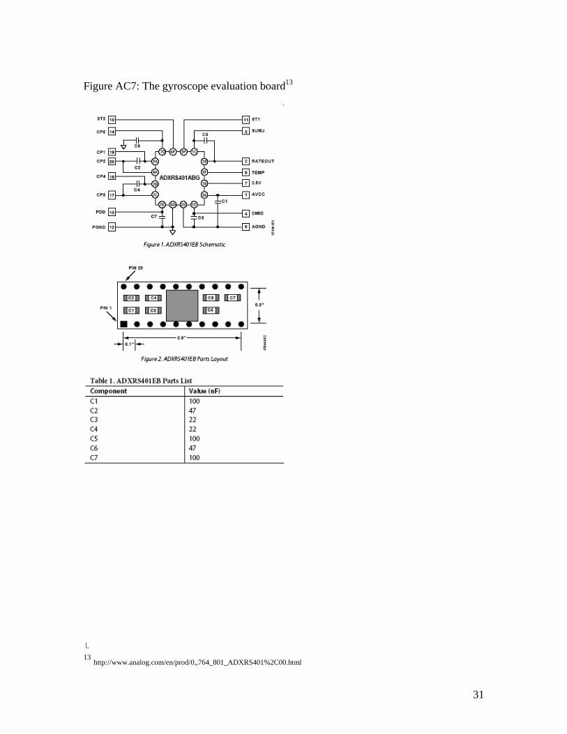
Figure AC7: The gyroscope evaluation board13
� 13 http://www.analog.com/en/prod/0,,764_801_ADXRS401%2C00.html
31

APPENDIX D: MULTISIM SCHEMATIC
32

APPENDIX E: ULTIBOARD LAYOUT
APPENDIX F: NAVIGATION MODULE CODE main.c /******* * ROV Navigation module * Maila Sepri, Samantha Brody * April 2005 * based on model skeleton module by Frederick Heckel * main.c : main loop * ------------------ * This module is compatible with both GCM * and Robomon ******/ #include "ROVfuncs.h" #include "GCM_IPC.h" int main(int argc, char *argv[]){ int option, i; int serialFile; int currentSpeeds[numPumps]; GCM_Module_IPC_Data mid; //for containing pid and module name
33

time_t lastKeepAlive=0; char buffer[512]; bool running=true; ROV_NavModData md; //for containing pid, name, caps, #caps, state, //and data from IPC messaging /* initialize module data */ GCM_log2("Initializing module data",INFO,false); initModule(&md); //sets state, capabilities, and name, and zeros all data /**** Parse options ****/ /* use getopt to parse command line options */ while(1){ option=getopt(argc,argv,"hc"); if(option==-1){ break; } switch(option){ case 'c': printCaps(md); return 0; break; case 'h': printUsage(); return 0; default: printUsage(); return 1; break; } } /**** GCM Log setup ****/ /* be sure to set the module name */ GCM_setModuleName(STRINGID); /*you should at least set this logfile name*/ GCM_logSetFilename("ROV.log"); /* uncomment to send WARNING/FATAL to a separate file */ // GCM_logSetErrFilename("ROV-errors.log"); /* uncomment to send GDEBUG to a separate file */ // GCM_logSetDebugFilename("ROV-debug.log"); /* uncomment to send DATA to a separate file */ // GCM_logSetDataFilename("ROV-data.log"); /* uncomment to get messages on stdout */ // GCM_logToggleStdout(); /* uncomment to get GCM to log GDEBUG messages */
34

GCM_logToggleDebug(); /**** Module/Communications setup ****/ sprintf(buffer,"Process id is %d\n",md.ROVpid); GCM_log2(buffer,GDEBUG,false); /* connect to IPC, define IPC types, and subscribe to messages */ GCM_log2("Initializing IPC",INFO,false); RovCheckIPC(&md); //uses IPC_subscribeData to handle GCM_COMON_COMMANDs /*set up serial port communications */ serialFile = openSerialPort("/dev/ttyS0", 9600); //initialize the currentSpeeds array to zero since all pumps will start //out stopped. for(i=0; i<numPumps; i++){ currentSpeeds[i] = 0; } /**** Main Loop ****/ /* false indicates the message will not be sent over IPC */ GCM_log2("Entering Main Loop",INFO,false); printf("entering main loop\n"); while(running){ /* make sure IPC is still connected */ if(!RovCheckIPC(&md)){ usleep(20000); continue; } //this is where subscribed commands are detected and handlers are called; IPC_listenClear(0); /* send a keepalive if it's time */ if((time(NULL)-lastKeepAlive)>=KEEPALIVEINTERVAL){ GCM_log2("Sending keepalive",INFO,false); mid.threadID=md.ROVpid; strncpy(mid.moduleName,STRINGID,sizeof(char)*64); IPC_publishData(GCM_COMMON_KEEPALIVE, &mid); lastKeepAlive=time(NULL); } switch(md.RovState){ //State = ACTIVE if just initialized or if message's mode = GCM_NAV_MOVE case STATE_ACTIVE: printf("STATE_ACTIVE\n"); /*set up serial port communications */ IPC_to_pic(&md, serialFile, currentSpeeds); break; case STATE_IDLE:
35

GCM_log2("Idling...",INFO,false); break; case STATE_SHUTDOWN: running=false; break; default: break; } /* set this to an appropriate value */ usleep(20000); } /**** Shutdown ****/ close(serialFile); terminateModuleIPC(); GCM_log2("Shutting down normally",INFO,false); return 0; } ROVfuncs.c /* Defines the functions for distributing direction and speed values to individual pumps and sending bytes over the serial port to the PIC.*/
#include <math.h> #include <time.h> #include <stdlib.h> #include <stdbool.h> #include <ROVfuncs.h> #include <termios.h> #include <stdio.h> #include <unistd.h> #include <string.h> #include <sys/time.h> #include <sys/file.h> #include <sys/stat.h> #include <signal.h> #include <ctype.h> /* masks for PIC to handle serial byte data; defined in ROVfuncs.h #define speedMask 0x18 #define pumpAddrMask 0x07 */ #define LO 0 #define HI !LO //The following three functions are for handling serial port communications //They were originally written for the svm library /********************************************************* openRaw Opens passed filename and sets its device to raw mode. Returns file descriptor.
36

raw mode is defined as: Off: echo, canonical input, extended processing, signals, break key, parity, 8th bit strip, flow control, output post processing On: 8 bit size **********************************************************/ int openRaw(const char * filename, mode_t io_flags) { struct termios term_info; int fd; fd = open(filename,io_flags); if (fd == -1) { /* maybe complain if TRACE is on */ return 0; } if(tcgetattr(fd,&term_info) <0) { /* complain - fd is not a terminal */ return 0; } /* turn off echo, canonical mode, extended processing, signals */ term_info.c_lflag &= ~(ECHO | ICANON | IEXTEN | ISIG); /* turn off break sig, cr->nl, parity off, 8 bit strip, flow control */ term_info.c_iflag &= ~(BRKINT | ICRNL | INPCK | ISTRIP | IXON); /* clear size, turn off parity bit */ term_info.c_cflag &= ~(CSIZE | PARENB); /* set size to 8 bits */ term_info.c_cflag |= CS8; /* turn output processing off */ term_info.c_oflag &= ~(OPOST); /* Set time and bytes to read at once */ term_info.c_cc[VTIME] = 0; term_info.c_cc[VMIN] = 0; if(tcsetattr(fd,TCSAFLUSH,&term_info) <0) return -1; return fd; } /********************************************************** setBaudRate Set the baud rate of an open device. Baud rate constants are found in <termios.h>. B9600 == 9600 baud *********************************************************/ int setBaudRate (int fd, speed_t baudRate) { struct termios terminfo; int error;
37
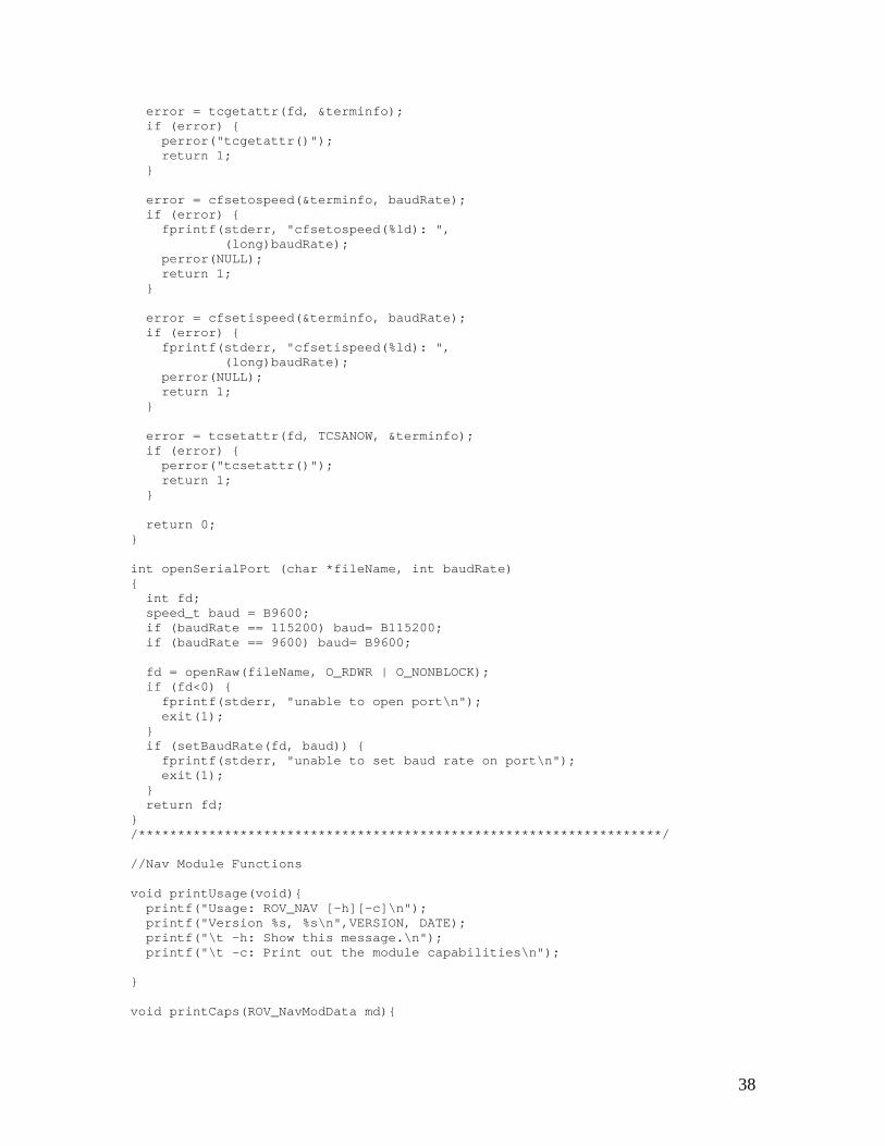
error = tcgetattr(fd, &terminfo); if (error) { perror("tcgetattr()"); return 1; } error = cfsetospeed(&terminfo, baudRate); if (error) { fprintf(stderr, "cfsetospeed(%ld): ", (long)baudRate); perror(NULL); return 1; } error = cfsetispeed(&terminfo, baudRate); if (error) { fprintf(stderr, "cfsetispeed(%ld): ", (long)baudRate); perror(NULL); return 1; } error = tcsetattr(fd, TCSANOW, &terminfo); if (error) { perror("tcsetattr()"); return 1; } return 0; } int openSerialPort (char *fileName, int baudRate) { int fd; speed_t baud = B9600; if (baudRate == 115200) baud= B115200; if (baudRate == 9600) baud= B9600; fd = openRaw(fileName, O_RDWR | O_NONBLOCK); if (fd<0) { fprintf(stderr, "unable to open port\n"); exit(1); } if (setBaudRate(fd, baud)) { fprintf(stderr, "unable to set baud rate on port\n"); exit(1); } return fd; } /*******************************************************************/ //Nav Module Functions void printUsage(void){ printf("Usage: ROV_NAV [-h][-c]\n"); printf("Version %s, %s\n",VERSION, DATE); printf("\t -h: Show this message.\n"); printf("\t -c: Print out the module capabilities\n"); } void printCaps(ROV_NavModData md){
38

printf("%d %d %d %d",md.ROV_capabilities[0], md.ROV_capabilities[1], md.ROV_capabilities[2], md.ROV_capabilities[3]); } void initModule(ROV_NavModData *md){ int i; md->ROVpid=getpid(); md->RovState=STATE_ACTIVE; md->numCapabilities=1; md->ROV_capabilities=malloc(sizeof(GCM_Capability)*1); md->ROV_capabilities[0]=NAV_MOVE; // md->ROV_capabilities[1]=NAV_SWIM; for(i=0; i<5; i++){ //data is an array of 5 ints md->messageData[i] = 0; } printf("initModule() successful\n"); } int greatest_speed(int cmd1, int cmd2, int cmd3){ int i; int max = 0; int commands[3]; commands[0] = cmd1; commands[1] = cmd2; commands[2] = cmd3; for(i=0; i<3; i++){ if(abs(commands[i])> abs(max)) max = commands[i]; } return max; } //look up how to pass arrays again void initializeArray(int array[numPumps], int initValue){ int i; for(i=0; i<numPumps; i++){ array[i] = initValue; } } //this function is called once each time the robot goes through the main loop in the ACTIVE state int IPC_to_pic(ROV_NavModData *md, int stream, int currSpeeds[numPumps]){ /* md->messageData[0:4] gives y, yaw, z, pitch, x speeds, in that order, as defined by the GCM_NAV_MOVE mode data. */ int i; //these ints store the speed value desired for each direction int back, fwd, left, right, turnR, turnL, up, down, noseUp, noseDown; int pumpSpeeds[numPumps]; //desired speed from new joystick message
39
int PICmsg[numPumps]; //holds pump addr and speed info int sendFlag[numPumps]; printf("in IPC_to_pic()\n"); initializeArray(pumpSpeeds, 0); initializeArray(PICmsg, 0); initializeArray(sendFlag, 0); /* //This works as planned (all arrays initialize to zero), so I'm commenting it out printf("checking initializer function:\n"); for(i=0; i<numPumps; i++){ printf("PICmsg[%d]=%d\n", i, PICmsg[i]); } */ //need to initialize these and md at the beginning //back = fwd = left = right = turnR = turnL = up = down = noseUp = noseDown = 0; for(i=0; i<5; i++){ printf(" joystick command[%d]: %d\n", i, md->messageData[i]); } /*These if statements distribute the speed commands just received over an IPC message to variables that describe the direction of desired motion. */ //for each of the 5 axes, assign speeds: STOP=0, SLOW=1, FAST=2 //y-axis (translation) if((md->messageData[0])< 0){ //backward = negative speeds back = md->messageData[0]; fwd = 0; printf("BACK=%d, fwd=%d\n", back, fwd); } else{ fwd = md->messageData[0]; //forward = positive speeds back = 0; printf("FWD=%d, back=%d\n", fwd, back); } //yaw (rotation) if((md->messageData[1])< 0){ //rot. L = negative speeds turnL = md->messageData[1]; turnR = 0; printf("TURN L=%d, turnR=%d\n", turnL, turnR); } else{ turnR = md->messageData[1]; //rot. R = positive speeds turnL = 0; printf("TURN R=%d, turnL=%d\n", turnR, turnL); } //z-axis (rise) if((md->messageData[2])< 0){ //down = negative speeds down = md->messageData[2]; up = 0; printf("DOWN=%d, up=%d\n", down, up); }
40
else{ up = md->messageData[2]; //up = positive speeds down = 0; printf("UP=%d, down=%d\n", up, down); } //pitch if((md->messageData[3])< 0){ //nose down = negative speeds noseDown = md->messageData[3]; noseUp = 0; printf("NOSE DOWN=%d, nose up=%d\n", noseDown, noseUp); } else{ noseUp = md->messageData[3]; //nose up = positive speeds noseDown = 0; printf("NOSE UP=%d, nose down=%d\n", noseUp, noseDown); } //x-axis; assign speed to correct dir if((md->messageData[4])< 0){ //left = negative speeds left = md->messageData[4]; right = 0; printf("LEFT=%d, right=%d\n", left, right); } else{ right = md->messageData[4]; //right = positive speeds left = 0; printf("RIGHT=%d, left=%d\n", right, left); } //Distribute speed values to appropriate pumps based on direction pumpSpeeds[0] = greatest_speed(fwd, left, turnR); //PumpA pumpSpeeds[1] = greatest_speed(fwd, right, turnL); //PumpB pumpSpeeds[2] = greatest_speed(back, left, turnL); //PumpC pumpSpeeds[3] = greatest_speed(back, right, turnR); //PumpD pumpSpeeds[4] = greatest_speed(down, noseUp, 0); //PumpE pumpSpeeds[5] = greatest_speed(up, noseDown, 0); //PumpF pumpSpeeds[6] = greatest_speed(up, noseUp, 0); //PumpG pumpSpeeds[7] = greatest_speed(down, noseDown, 0); //PumpH for(i=0; i<8; i++){ printf("pump[%d] speed = %d\n", i, pumpSpeeds[i]); } /*Check if speed per pump has changed during this cycle. Compile the speed and address values into an 8-bit int, store an array of the ints, and send the compiled sets of 8 bits over the serial port if the speeds have changed*/ for(i=0; i<numPumps; i++){ if(pumpSpeeds[i] == currSpeeds[i]){ sendFlag[i] = LO; } else{ //speed no longer the same... currSpeeds[i] = pumpSpeeds[i]; sendFlag[i] = HI; } PICmsg[i] = (((currSpeeds[i]<<3) & speedMask) | (i & pumpAddrMask)); if(sendFlag[i]){ printf("PICmsg[%d]=0x%02hhx\n", i, PICmsg[i]); write(stream, &(PICmsg[i]),1); usleep(10000); //delay for 10ms to allow PIC to process last byte
41
} } return(1); }
RovIPCFuncs.c /* Defines functions for accepting and handling IPC messages, which ll be broadcasted by the Joystick Module.*/ wi
#include <ROVfuncs.h> #include <ipc.h> /*checks to make sure that IPC is connected. if it isn't, attempts to connect and do all necessary initialization */ bool RovCheckIPC(ROV_NavModData *md){ GCM_Module_IPC_Data mid; //gets pid and name if(!IPC_isConnected()){ GCM_log2("IPC disconnected. Attempting to reconnect", WARNING,false); if(IPC_connectModule(STRINGID,"localhost") !=IPC_OK){ return false; } GCM_log2("IPC [re]connected\n",INFO,false); GCM_defineCommonIPCTypes(); mid.threadID = md->ROVpid; strncpy(mid.moduleName, STRINGID,64); IPC_publishData(GCM_COMMON_STARTUP, &mid); /*Give NAV Module the capacity to receive and recognize messages in the GCM_COMMON_COMMAND format. The message data is stored in md using the handler and thus passed to the main function through md when ROVCheckIPC is called.*/ IPC_subscribeData(GCM_COMMON_COMMAND,RovCommonHandler,md); GCM_log2("Subscribed to messages.",INFO,false); return true; }else{ return true; } return false; } /* if you want to send a termination notice, do it here. */ int terminateModuleIPC(void) { IPC_disconnect(); return(0); }
42
void RovCommonHandler(MSG_INSTANCE msgInstance, void *callData,void *clientData) { //callData used to store data from message //clientData used to pass any needed info to/from the main loop //typedef in ROVfuncs.h (pid, capabs, state, data) ROV_NavModData *md = clientData; //typedef in GCM_IPC.h (mode, pid, name, data, cdata) GCM_Common_Command *mode = callData; //typedef in GCM_IPC.h (threadID and module name) GCM_Module_IPC_Data mid; //typedef in GCM_IPC.h (pid, name, variable cap, bool cap) GCM_Common_Capabilities caps; int i; GCM_log2("In RovCommonHandler",GDEBUG,false); if(strncmp(mode->name,STRINGID,64)==0 ||strncmp(mode->name,"all",64)==0){ GCM_log2("In RovCommonHandler still",GDEBUG,false); switch(mode->mode){ case GCM_NAV_MOVE: md->RovState=STATE_ACTIVE; printf("received IPC message: mode=GCM_NAV_MOVE\n"); //pass data from message to struct accessible from main loop for(i=0; i<5; i++){ md->messageData[i]=(int)(mode->data[i]); printf(" joystick data[%d]= %d\n", i, md->messageData[i]); } break; //prob not used case GCM_COMMON_IDLE: md->RovState=STATE_IDLE; break; case GCM_COMMON_QUIT: md->RovState=STATE_SHUTDOWN; break; case GCM_COMMON_PING: mid.threadID=md->ROVpid; strncpy(mid.moduleName,STRINGID,64); IPC_publishData(GCM_COMMON_STARTUP, &mid); break; case GCM_COMMON_BCAST_CAP: strncpy(caps.name,STRINGID,64); caps.pid=md->ROVpid; caps.caps.size=md->numCapabilities; caps.caps.data=malloc(sizeof(GCM_Capability)*md->numCapabilities); for(i=0;i<md->numCapabilities;i++){ caps.caps.data[i]=md->ROV_capabilities[i]; } caps.active.size=0; IPC_publishData(GCM_COMMON_CAPABILITIES, &caps);
43

break; // case GCM_SET_PARAM: // break; default: GCM_log2("Unhandled command received, addressed to us or all",WARNING,false); } }else{ return; } IPC_freeData(IPC_msgFormatter(GCM_COMMON_COMMAND), callData); return; } testSerial.c /* Allows us to send GCM_COMMON_COMMAND messages to the ROV Nav Module using the command line to write the messages.*/ #include <stdlib.h> #include <stdio.h> #include <string.h> #include <math.h> #include <unistd.h> #include <time.h> #include <ipc.h> #include <GCM_IPC.h> #include <GCM_Log.h> //the command line shoud read "./manualCommand ROV_JOYSTICK y yaw z pitch x" int main(int argc, char *argv[]) { char type[512]; int i; // this is a common command format GCM_Common_Command mode; // init IPC with the name of the process GCM_initIPC("UserCommand"); strcpy(type, argv[1]); if(strcmp(type, "ROV_JOYSTICK") == 0){ mode.mode = GCM_NAV_MOVE; mode.data[0] = atoi(argv[2]); mode.data[1] = atoi(argv[3]); mode.data[2] = atoi(argv[4]); mode.data[3] = atoi(argv[5]); mode.data[4] = atoi(argv[6]); mode.data[5] = 0; //unused printf("after assignment:\n"); for(i=0; i<6; i++){ printf(" joystick data[%d] = %e\n", i, mode.data[i]);
44

} } else { // they didn't follow the syntax :( exit(-1); } // send to all modules strcpy(mode.name, "all"); // call IPC_publishData(message type, message data) to send the message IPC_publishData(GCM_COMMON_COMMAND, &mode); // terminate the IPC connection GCM_terminateIPC("UserCommand"); return(0); } manualCommand.c /* Allows us to send GCM_COMMON_COMMAND messages to the ROV Nav Module using the command line to write the messages.*/ #include <stdlib.h> #include <stdio.h> #include <string.h> #include <math.h> #include <unistd.h> #include <time.h> #include <ipc.h> #include <GCM_IPC.h> #include <GCM_Log.h> //the command line shoud read "./manualCommand ROV_JOYSTICK y yaw z pitch x" int main(int argc, char *argv[]) { char type[512]; int i; // this is a common command format GCM_Common_Command mode; // init IPC with the name of the process GCM_initIPC("UserCommand"); strcpy(type, argv[1]); if(strcmp(type, "ROV_JOYSTICK") == 0){ mode.mode = GCM_NAV_MOVE; mode.data[0] = atoi(argv[2]); mode.data[1] = atoi(argv[3]); mode.data[2] = atoi(argv[4]); mode.data[3] = atoi(argv[5]); mode.data[4] = atoi(argv[6]); mode.data[5] = 0; //unused printf("after assignment:\n"); for(i=0; i<6; i++){ printf(" joystick data[%d] = %e\n", i, mode.data[i]);
45

} } else { // they didn't follow the syntax :( exit(-1); } // send to all modules strcpy(mode.name, "all"); // call IPC_publishData(message type, message data) to send the message IPC_publishData(GCM_COMMON_COMMAND, &mode); // terminate the IPC connection GCM_terminateIPC("UserCommand"); return(0); }
ROVfuncs.h /* Header file for ROV Module*/
#ifndef ROVFUNCS_H #define ROVFUNCS_H #include <GCM.h> #include <stdio.h> #include <string.h> #include <getopt.h> //We need this for getting cmd line args in main.c #include <unistd.h> /* Simple serial port interface */ #include <stdlib.h> #include <termios.h> #include <unistd.h> #include <sys/time.h> #include <sys/file.h> #include <sys/stat.h> #include <signal.h> #include <ctype.h> #define VERSION "1.0.0" #define DATE "April 22, 2005" #define KEEPALIVEINTERVAL 6 #define STRINGID "ROV_NAV" #define numPumps 8 //Serial port opening/config functions int openRaw(const char * filename, mode_t io_flags); int setBaudRate (int fd, speed_t baudRate); int openSerialPort (char *fileName, int baudRate); /*This struct contains the following fields: process ID for the ROV; changes each time the Nav Module is run prob only NAV_SWIM, defined in GCM_IPC.c so, prob 1 capability usually STATE_ACTIVE...we check for the STATE_SHUTDOWN msg; def'd in GCM_IPC.c
46

this is the message sent to our module over IPC */ typedef struct { pid_t ROVpid; GCM_Capability *ROV_capabilities; int numCapabilities; GCM_ModuleState RovState; int messageData[5]; } ROV_NavModData; //These functions are used in the main loop to deal with IPC commands void printUsage(void); void printCaps(ROV_NavModData md); void initModule(ROV_NavModData *md); /*these fctns written by Fritz to check for messages, end messaging, and handle messages. I changed their names to specify that they're internal to the rov nav module*/ bool RovCheckIPC(ROV_NavModData *md); //defined in RovIPCFuncs.c int terminateModuleIPC(void); void RovCommonHandler(MSG_INSTANCE msgInstance, void *callData, void *clientData); //these definitions used in the Nav Modlule, not GCM //typedef enum{ ROV_STOP, ROV_SLOW, ROV_FAST} GCM_RovSpeed; //typedef enum{ ROV_X, ROV_Y, ROV_Z, ROV_P, ROV_YAW} GCM_RovAxis; /*//ROVCommonHandler reads GCM_Common_Command struct (which looks like this): typedef struct{ GCM_Common_Mode mode; long pid; char name[64]; double data[6]; char cdata[64]; } GCM_Common_Command; and passes the data/settings into an ROV_NavModData struct */ //masks for handling Nick's Joystick variables #define speedMask 0x18 #define pumpAddrMask 0x07 //functions for distributing pump speeds int greatest_speed(int cmd1, int cmd2, int cmd3); void initializeArray(int array[numPumps], int initValue); int IPC_to_pic(ROV_NavModData *md, int fd,int currSpeeds[numPumps]); #endif
47

APPENDIX G: PIC PROGRAM CODE /******************************************************* This program is intended to read a PortA analog input pin, perform A/D conversion, and output the 8-bit digital value on the one of the PIC pins in the B Port. ******************************************************** Maila Sepri, Samantha Brody, Alexey Rostapshov Swarthmore College April 2005 ********************************************************/ #include "\\Data-software\classes\Natural Sciences + Engineering\Engineering\Transfer\ROV\pump1\pump1.h" //#include <math.h> //#include <stdio.h> #include <stdlib.h> #define ORIENTPRINT TRUE #define TEMPPRINT TRUE #define PUMPPRINT TRUE #define LO 0 #define HI 1 #define AddrMask 0x07 //00000111 #define SpeedMask 0x18 //00011000 #define DELAYTIME 5 #define DUTYCYCLETIME 500 #define MAXTEMP 80 typedef enum{stop, slow, fast} speed_type; typedef enum{first, second} duty_type; #use fixed_io(b_outputs = PIN_B0, PIN_B1, PIN_B2, PIN_B3, PIN_B4, PIN_B5, PIN_B6, PIN_B7) speed_type identify_speed(int speed){ speed_type speed_value; switch((speed & SpeedMask)>>3){ case(0): {speed_value = stop; break; } case(1): {speed_value = slow; break; } case(2): {speed_value = fast; break; } default: {speed_value=stop; break; } } return speed_value; } void main() {
48
int running=TRUE; int j=0, k=0, z=0; // assorted loop counters // Tx/Rx variables. int num_changes=0; // the number of changes received int pump_commands[8]; // for storing commands of up to 8 pumps // Duty cycle variables. int duty_delays = DUTYCYCLETIME/DELAYTIME; // The number of cycles we need to wait before updating pump duty cycle states int delay_count=0; // The number of delays since last duty cycle update duty_type duty_flag=first; // Initialize the duty_flag value // Speed variables. int slow_pumps[8]={0,0,0,0,0,0,0,0}; // the pump number of the slow pumps int slow_pump_cycle[8]={0,0,0,0,0,0,0,0}; // the duty cycle location of each pump speed_type speed = stop; // Variables associated with the gyros. int gyro_configed=TRUE, first_cycle=TRUE; // Whether or not gyro has been calibrated. long gyro1temp_raw, rateout1_raw; // The raw A/D values from sensors float gyro1temp, gyro1_volts; // The shifted and converted raw values. float gyro1calib_volts = 0;// Used for calibrating the gyro during the first duty cycle. long gyro1_volts_int=0, gyro1calib_int=0, gyro1calib_final=0; // Summation of turns float turn_sum=0; int to_sum=FALSE; //Initialize A/D conversion setup_adc(ADC_CLOCK_DIV_2); set_adc_channel(0); // Setup the A/D pins setup_adc_ports(sAN0); //pin 2 setup_adc_ports(sAN1); //pin 3 setup_adc_ports(sAN2); //pin 4 setup_adc_ports(sAN3); //pin 5 setup_adc_ports(sAN4); //pin 6 // Configure the digital I/O; use pins (RB0:RB7) for outputs to MOSFETs output_low(PIN_B0); output_low(PIN_B1); output_low(PIN_B2);
49
output_low(PIN_B3); output_low(PIN_B4); output_low(PIN_B5); output_low(PIN_B6); output_low(PIN_B7); printf("Initialized... all pumps off\n\r"); do{ while(kbhit()){ //possible problem: continuous movement means never executing commands pump_commands[num_changes]=getc(); //reads commands from Rx line in bytes num_changes++; } for(j=0; j<num_changes; j++){ speed=identify_speed(pump_commands[j]); if(speed==stop){ switch(pump_commands[j] & AddrMask){ case(0): {output_low(PIN_B0); //PumpA slow_pumps[0] = 0; if(PUMPPRINT){printf("PumpA=STOP \n\r");} break; } case(1): {output_low(PIN_B1); //PumpB slow_pumps[1] = 0; if(PUMPPRINT){printf("PumpB=STOP \n\r");} break; } case(2): {output_low(PIN_B2); //PumpC slow_pumps[2] = 0; if(PUMPPRINT){printf("PumpC=STOP \n\r");} break; } case(3): {output_low(PIN_B3); //PumpD slow_pumps[3] = 0; if(PUMPPRINT){printf("PumpD=STOP \n\r");} break; } case(4): {output_low(PIN_B4); //PumpE slow_pumps[4] = 0; if(PUMPPRINT){printf("PumpE=STOP \n\r");} break; } case(5): {output_low(PIN_B5); //PumpF slow_pumps[5] = 0; if(PUMPPRINT){printf("PumpF=STOP \n\r");} break; } case(6): {output_low(PIN_B6); //PumpG slow_pumps[6] = 0; if(PUMPPRINT){printf("PumpG=STOP \n\r");} break; } case(7): {output_low(PIN_B7); //PumpH slow_pumps[7] = 0;
50

if(PUMPPRINT){printf("PumpH=STOP \n\r");} break; } default: {printf("invalid pump address for STOP command.\n\r"); break; } } } else if(speed==fast){ switch(pump_commands[j] & AddrMask){ case(0): {output_high(PIN_B0); //PumpA slow_pumps[0] = 0; if(PUMPPRINT){printf("PumpA=FAST \n\r");} break; } case(1): {output_high(PIN_B1); //PumpB slow_pumps[1] = 0; if(PUMPPRINT){printf("PumpB=FAST \n\r");} break; } case(2): {output_high(PIN_B2); //PumpC slow_pumps[2] = 0; if(PUMPPRINT){printf("PumpC=FAST \n\r");} break; } case(3): {output_high(PIN_B3); //PumpD slow_pumps[3] = 0; if(PUMPPRINT){printf("PumpD=FAST \n\r");} break; } case(4): {output_high(PIN_B4); //PumpE slow_pumps[4] = 0; if(PUMPPRINT){printf("PumpE=FAST \n\r");} break; } case(5): {output_high(PIN_B5); //PumpF slow_pumps[5] = 0; if(PUMPPRINT){printf("PumpF=FAST \n\r");} break; } case(6): {output_high(PIN_B6); //PumpG slow_pumps[6] = 0; if(PUMPPRINT){printf("PumpG=FAST \n\r");} break; } case(7): {output_high(PIN_B7); //PumpH slow_pumps[7] = 0; if(PUMPPRINT){printf("PumpH=FAST \n\r");} break; } default:{printf("invalid pump address for FAST command.\n\r"); break; }
51
} } else if(speed==slow){ switch(pump_commands[j] & AddrMask){ case(0): {output_high(PIN_B0); //PumpA slow_pumps[0] = 1; slow_pump_cycle[0] = duty_flag; if(PUMPPRINT){printf("PumpA=SLOW \n\r");} break; } case(1): {output_high(PIN_B1); //PumpB slow_pumps[1] = 1; slow_pump_cycle[1] = duty_flag; if(PUMPPRINT){printf("PumpB=SLOW \n\r");} break; } case(2): {output_high(PIN_B2); //PumpC slow_pumps[2] = 1; printf("PumpC=SLOW \n\r"); if(PUMPPRINT){slow_pump_cycle[2] = duty_flag;} break; } case(3): {output_high(PIN_B3); //PumpD slow_pumps[3] = 1; slow_pump_cycle[3] = duty_flag; if(PUMPPRINT){printf("PumpD=SLOW \n\r");} break; } case(4): {output_high(PIN_B4); //PumpE slow_pumps[4] = 1; slow_pump_cycle[4] = duty_flag; if(PUMPPRINT){printf("PumpE=SLOW \n\r");} break; } case(5): {output_high(PIN_B5); //PumpF slow_pumps[5] = 1; slow_pump_cycle[5] = duty_flag; if(PUMPPRINT){printf("PumpF=SLOW \n\r");} break; } case(6): {output_high(PIN_B6); //PumpG slow_pumps[6] = 1; slow_pump_cycle[6] = duty_flag; if(PUMPPRINT){printf("PumpG=SLOW \n\r");} break; } case(7): {output_high(PIN_B7); //PumpH slow_pumps[7] = 1; slow_pump_cycle[7] = duty_flag; if(PUMPPRINT){printf("PumpH=SLOW \n\r");} break; } default:{printf("invalid pump address for SLOW command.\n\r"); break; }
52

} } } // End for updating pump states num_changes=0; // This loop updates the duty cycle for the slow pumps. for(k=0; k < 8; k++){ if((slow_pumps[k]==1) & (slow_pump_cycle[k] == duty_flag)){ switch(k){ case(0): {output_high(PIN_B0); //PumpA break; } case(1): {output_high(PIN_B1); //PumpB break; } case(2): {output_high(PIN_B2); //PumpC break; } case(3): {output_high(PIN_B3); //PumpD break; } case(4): {output_high(PIN_B4); //PumpE break; } case(5): {output_high(PIN_B5); //PumpF break; } case(6): {output_high(PIN_B6); //PumpG break; } case(7): {output_high(PIN_B7); //PumpH break; } default:{printf("Duty cycle error on HI!\n\r"); break; } } } else if((slow_pumps[k]==1)){ switch(k){ case(0): {output_low(PIN_B0); //PumpA break; } case(1): {output_low(PIN_B1); //PumpB break; } case(2): {output_low(PIN_B2); //PumpC break; } case(3): {output_low(PIN_B3); //PumpD break; } case(4): {output_low(PIN_B4); //PumpE break;
53

} case(5): {output_low(PIN_B5); //PumpF break; } case(6): {output_low(PIN_B6); //PumpG break; } case(7): {output_low(PIN_B7); //PumpH break; } default:{printf("Duty cycle error on LO!\n\r"); break; } } } } // end of duty cycle handle loop // Read RATEOUT value from Gyroscope 1 set_adc_channel(0); rateout1_raw = read_adc(); gyro1_volts = rateout1_raw>>1; gyro1_volts = (gyro1_volts-gyro1calib_final-255)*5/512; // Adjust for noise if((gyro1_volts<=.03)&(gyro1_volts>=-.02)){ gyro1_volts=0; } // Read TEMP value from Gyroscope 1 set_adc_channel(1); gyro1temp_raw = read_adc(); gyro1temp = gyro1temp_raw>>1; gyro1temp = 27.0 + ((gyro1temp*5/512-2.5)/.0084); if(gyro1temp>=MAXTEMP){ printf("WARNING! TEMPERATURE IS %d CELCIUS! SHUTTING DOWN...\n\r", (int)gyro1temp); running = FALSE; } delay_ms(DELAYTIME); delay_count++; if(delay_count == duty_delays){ duty_flag = duty_flag+1; delay_count = 0; if(!gyro_configed){ gyro_configed=TRUE; gyro1calib_int=gyro1calib_int/duty_delays; gyro1calib_final = gyro1calib_int; printf("Gyroscope calibrated (Adjusting by -%f Volts) \n\r", (float)gyro1calib_final*5/512); gyro1_volts=rateout1_raw>>1; gyro1_volts = 0; to_sum=TRUE; }
54

if(first_cycle){first_cycle=FALSE;gyro_configed=FALSE;printf("Calibrating gyroscope...\n\r");} // Gyro powered up... now calibrate. else{ if(ORIENTPRINT){printf("Temperature (Celcius): %d ", (int)gyro1temp);} if(TEMPPRINT){printf("Orientation (degrees): %d\n\r", (int)turn_sum);} } } if(to_sum){ turn_sum=turn_sum-gyro1_volts*.687; } if(!gyro_configed){gyro1calib_int=gyro1calib_int+((rateout1_raw>>1)-255);} } while(running); } // end main
55

References [1] Bohm, Harry, and Jensen, Vickie. Build Your Own Underwater Robot and Other Wet
Projects [2] “CCS-FAQ: How do I connect the CCS ICD to my own hardware?”
http://www.ccsinfo.com/faq/?45, 2004. [3] Flurie, Hollinger, and Pezzementi. “Design and Construction of an Indoor Robotic
Blimp for Urban Search and Rescue Tasks,” E90 Final Report, 2005. [4] “WHOI Marine Operations – Jason II/Medea Virtual Control Van,”
http://www.whoi.edu/marine/ndsf/vehicles/jason/van_cruises.html, 21-Mar-2005.
56


![REMOTELY OPERATED VEHICLE [ MINI-ROV ] …€¦ · REMOTELY OPERATED VEHICLE [ MINI-ROV ]ELECTRICAL MANIPULATOR ARM UNDERWATER INSPECTION & OPERATION UP TO 300 METER DEEP Targeted](https://static.documents.pub/doc/80x56/5ac8cc3b7f8b9a7d548ca5ff/remotely-operated-vehicle-mini-rov-remotely-operated-vehicle-mini-rov.jpg)