Design and Construction of Butterfly Web Bridge Kenichi Kata 1 , Kenichiro Ashizuka 2 , Kenji Miyamoto 2 , Kenichi Nakatsumi 1* , 1 Sumitomo Mitsui Construction CO.,Ltd. Japan 2 West Nippon Expressway Co.,Ltd. Kyushu Branch Office, Japan * 2-1-6, Tsukuda, Chuo-ku, Tokyo 104-0051, Japan [email protected], [email protected][email protected], [email protected], ABSTRACT A new type of bridge called “Butterfly Web Bridge” is under construction in Japan. This bridge, named Takubogawa Bridge, is a highway bridge and has 10 spans including the 87.5m maximum span length. The butterfly web structure uses butterfly-shaped prefabricated panels with a thickness of 150 mm in the web. The material for the components of the web is the 80 MPa concrete and tensile stress areas are reinforced with prestressing single steels. Moreover, the 150 mm panel has no reinforcing steels but is reinforced by steel fibers. And this bridge is constructed by free cantilever method. The butterfly web is prefabricated in the concrete factory and its weight is 3.3 t, enabling construction of a main girder lighter than would be possible with an ordinary concrete web. So, the construction speed of cantilevering can be advanced about 50% compared with conventional cast-in-situ method. Keywords. Prefabricated Panel, Fiber Reinforced Concrete, Light weight, Construction Speed, Low maintenance, 1. INTRODUCTION It is important to reduce the superstructure weight in the earthquake prone country like Japan. Therefore, corrugated steel web bridges have been applied in many projects. However, the composite structure of steel components and of their joints with the concrete in these bridges produces a requirement for special machining technology and for on-site welding. And maintenance cost should be needed to keep durability of the structure during their design life time. So, the new type of structure “Butterfly Web 1, 3, 4 ” reported in this paper was devised for the purpose of resolving this sort of issue with composite bridges. It can meet the requirement of light weight and low maintenance and make it possible to reduce cut construction costs. The Takubogawa Bridge is the world’s first to use a butterfly web structure with butterfly- shaped concrete panels utilized in the web of the main girder as a means for erecting the bridge more efficiently and for reducing construction cost. The butterfly web structure uses butterfly-shaped panels in the web. With respect to shear force acting on the web, it behaves similarly to a double Warren truss structure (Figure 1). The material for the components of the web is concrete and tensile stress areas are reinforced with prestressing single steels.
A new type of bridge called “Butterfly Web Bridge” is under construction in Japan. This bridge, named Takubogawa Bridge, is a highway bridge and has 10 spans including the 87.5m maximum span length. The butterfly web structure uses butterfly-shaped prefabricated panels with a thickness of 150 mm in the web. The material for the components of the web is the 80 MPa concrete and tensile stress areas are reinforced with prestressing single steels. Moreover, the 150 mm panel has no reinforcing steels but is reinforced by steel fibers. And this bridge is constructed by free cantilever method. The butterfly web is prefabricated in the concrete factory and its weight is 3.3 t, enabling construction of a main girder lighter than would be possible with an ordinary concrete web. So, the construction speed of cantilevering can be advanced about 50% compared with conventional cast-in-situ method.
It is important to reduce the superstructure weight in the earthquake prone country like Japan. Therefore, corrugated steel web bridges have been applied in many projects. However, the composite structure of steel components and of their joints with the concrete in these bridges produces a requirement for special machining technology and for on-site welding. And maintenance cost should be needed to keep durability of the structure during their design life time.
So, the new type of structure “Butterfly Web1, 3, 4” reported in this paper was devised for the purpose of resolving this sort of issue with composite bridges. It can meet the requirement of light weight and low maintenance and make it possible to reduce cut construction costs.
The Takubogawa Bridge is the world’s first to use a butterfly web structure with butterfly-shaped concrete panels utilized in the web of the main girder as a means for erecting the bridge more efficiently and for reducing construction cost. The butterfly web structure uses butterfly-shaped panels in the web. With respect to shear force acting on the web, it behaves similarly to a double Warren truss structure (Figure 1). The material for the components of the web is concrete and tensile stress areas are reinforced with prestressing single steels.
cbx054
Text Box
Third International Conference on Sustainable Construction Materials and Technologies http://www.claisse.info/Proceedings.htm
Figure 1. Structural properties of Butterfly web
2. DESIGN OF BUTTERFLY WEB
2.1. Bridge Outline. Takubogawa Bridge is located in the city of Hyuga, Miyazaki, Japan, and forms part of the Higashi-Kyushu Expressway that runs between the major cities of Kitakyushu and Kagoshima. It is a 10-span continuous prestressed concrete bridge and has the 712.5m total length including the 87.5m maximum span length (Figure 2,3).
Figure 2. Takubogawa Bridge
Figure 3. Side view of the maximum span
2.2. Construction Material Used. The butterfly web comprises precast panels fabricated off-site at a plant using high strength fiber reinforced concrete with specified design strength
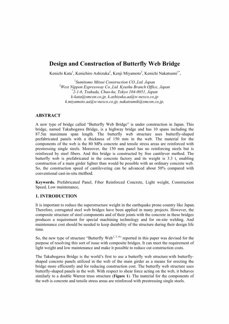
of 80 MPa. Steel fibers are used enhance shear capacity (Photo 1). Inside the panels, prestressing steel members are placed to align with the orientation of tension acting on the panels. Prestressing is used as the method of pretensioning. The prestressing steel components are 15.2 mm diameter strands with intended surfaces to enhance the adhesion of concrete (Photo 2). There is no reinforcing steel, which makes the panels easy to work with and makes maintenance easy.
Photo 1. Steel fibers Photo 2. Strand with indented surface
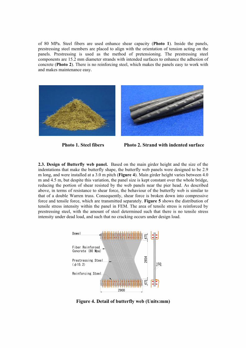
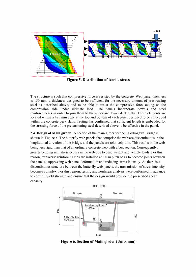
2.3. Design of Butterfly web panel. Based on the main girder height and the size of the indentations that make the butterfly shape, the butterfly web panels were designed to be 2.9 m long, and were installed at a 3.0 m pitch (Figure 4). Main girder height varies between 4.0 m and 4.5 m, but despite this variation, the panel size is kept constant over the whole bridge, reducing the portion of shear resisted by the web panels near the pier head. As described above, in terms of resistance to shear force, the behaviour of the butterfly web is similar to that of a double Warren truss. Consequently, shear force is broken down into compressive force and tensile force, which are transmitted separately. Figure 5 shows the distribution of tensile stress intensity within the panel in FEM. The area of tensile stress is reinforced by prestressing steel, with the amount of steel determined such that there is no tensile stress intensity under dead load, and such that no cracking occurs under design load.
Figure 4. Detail of butterfly web (Units:mm)
475
2654
475
2900
Dowel
150
Reinforcing Steel
Prestressing Steel
Fiber Reinforced
(φ15.2)
Concrete (80 Mpa)
Figure 5. Distribution of tensile stress
The structure is such that compressive force is resisted by the concrete. Web panel thickness is 150 mm, a thickness designed to be sufficient for the necessary amount of prestressing steel as described above, and to be able to resist the compressive force acting on the compression side under ultimate load. The panels incorporate dowels and steel reinforcements in order to join them to the upper and lower deck slabs. These elements are located within a 475 mm zone at the top and bottom of each panel designed to be embedded within the concrete deck slabs. Testing has confirmed that sufficient length is embedded for the stressing force of the pretensioning steel described above to be effective in the panel.
2.4. Design of Main girder. A section of the main girder for the Takubogawa Bridge is shown in Figure 6. The butterfly web panels that comprise the web are discontinuous in the longitudinal direction of the bridge, and the panels are relatively thin. This results in the web being less rigid than that of an ordinary concrete web with a box section. Consequently, greater bending unit stress occurs in the web due to dead weight and vehicle loads. For this reason, transverse reinforcing ribs are installed at 3.0 m pitch so as to become joints between the panels, suppressing web panel deformation and reducing stress intensity. As there is a discontinuous structure between the butterfly web panels, the transmission of stress intensity becomes complex. For this reason, testing and nonlinear analysis were performed in advance to confirm yield strength and ensure that the design would provide the prescribed shear capacity.
Figure 6. Section of Main girder (Units:mm)
Load
Tensile stress
Butterfly Web
(t=150mm)
10150~10350
720220
250Mid span Pier head
5460
480
4500
4000
Reinforcing Ribs
(t=250mm)
3. CONSTRUCTION
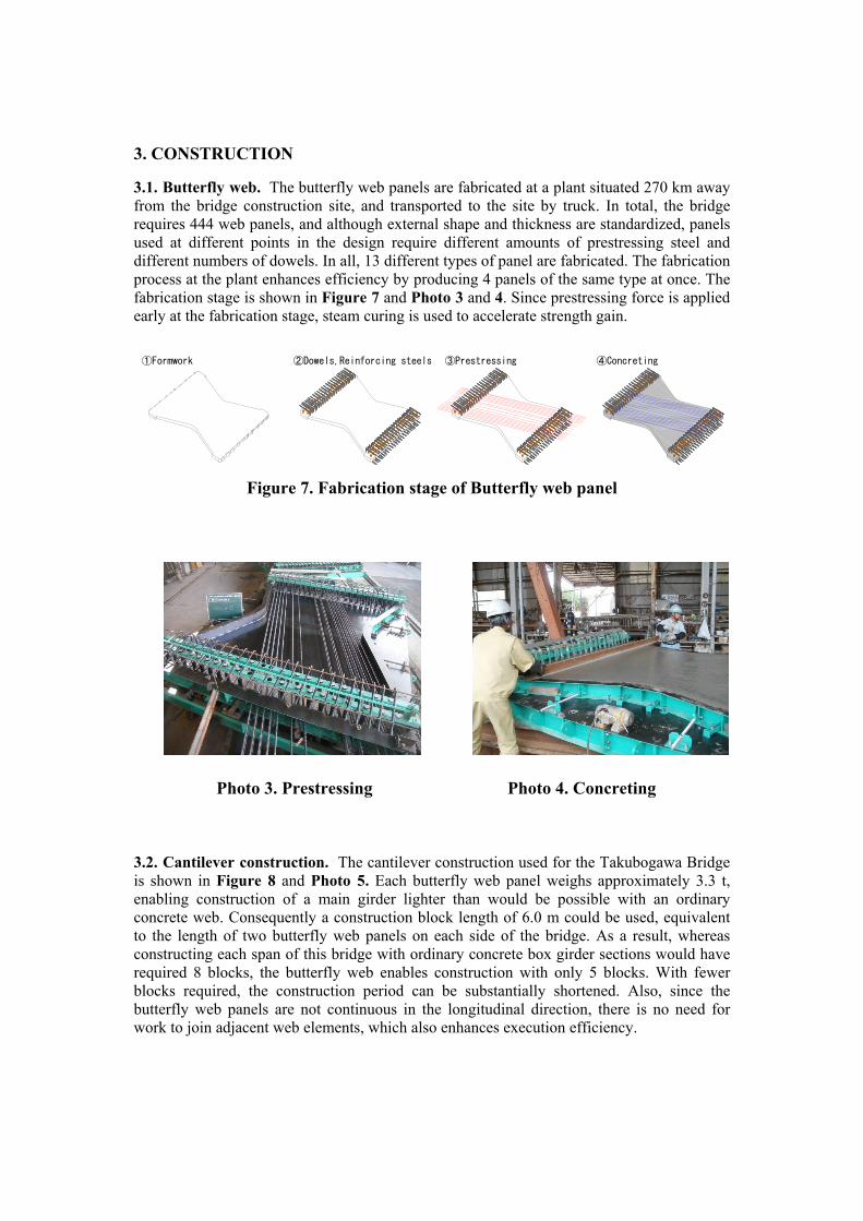
3.1. Butterfly web. The butterfly web panels are fabricated at a plant situated 270 km away from the bridge construction site, and transported to the site by truck. In total, the bridge requires 444 web panels, and although external shape and thickness are standardized, panels used at different points in the design require different amounts of prestressing steel and different numbers of dowels. In all, 13 different types of panel are fabricated. The fabrication process at the plant enhances efficiency by producing 4 panels of the same type at once. The fabrication stage is shown in Figure 7 and Photo 3 and 4. Since prestressing force is applied early at the fabrication stage, steam curing is used to accelerate strength gain.
Figure 7. Fabrication stage of Butterfly web panel
Photo 3. Prestressing Photo 4. Concreting
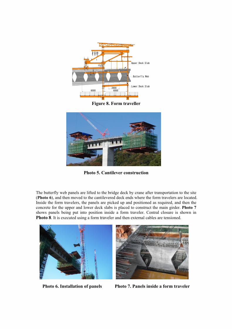
3.2. Cantilever construction. The cantilever construction used for the Takubogawa Bridge is shown in Figure 8 and Photo 5. Each butterfly web panel weighs approximately 3.3 t, enabling construction of a main girder lighter than would be possible with an ordinary concrete web. Consequently a construction block length of 6.0 m could be used, equivalent to the length of two butterfly web panels on each side of the bridge. As a result, whereas constructing each span of this bridge with ordinary concrete box girder sections would have required 8 blocks, the butterfly web enables construction with only 5 blocks. With fewer blocks required, the construction period can be substantially shortened. Also, since the butterfly web panels are not continuous in the longitudinal direction, there is no need for work to join adjacent web elements, which also enhances execution efficiency.
The butterfly web panels are lifted to the bridge deck by crane after transportation to the site (Photo 6), and then moved to the cantilevered deck ends where the form travelers are located. Inside the form travelers, the panels are picked up and positioned as required, and then the concrete for the upper and lower deck slabs is placed to construct the main girder. Photo 7 shows panels being put into position inside a form traveler. Central closure is shown in Photo 8. It is executed using a form traveler and then external cables are tensioned.
Photo 6. Installation of panels Photo 7. Panels inside a form traveler
6000
Lower Deck Slab
Upper Deck Slab
2900
Butterfly Web
6000
Photo 8. Central closure Photo 9. External cable
4. SUSTINABILITY
Using of the butterfly web means that, this bridge uses less concrete for the main girder than an ordinary concrete web box girder structure. Comparison ordinary box girder and butterfly web is shown in Table 1. And trial calculations made using the method set out in Reference 2 indicate that the superstructure used for the bridge represents a 186 t cut in CO2 emissions (Table 2).
Table 1. Comparison Box girder and Butterfly web
Table 2. CO2 emissions (Superstructure)
volume CO2 volume CO2 quantity CO2 quantity CO2 ratioBox Girder 6022m3 1770.5t 0.0t 1247.8t 957.1t 287.3t 379.8t 3107.4t 1.00
Cantilever Erection Cantilever ErectionColumn CapitalCentral Closure Central Closure
5.2m
5. CONCLUSIONS
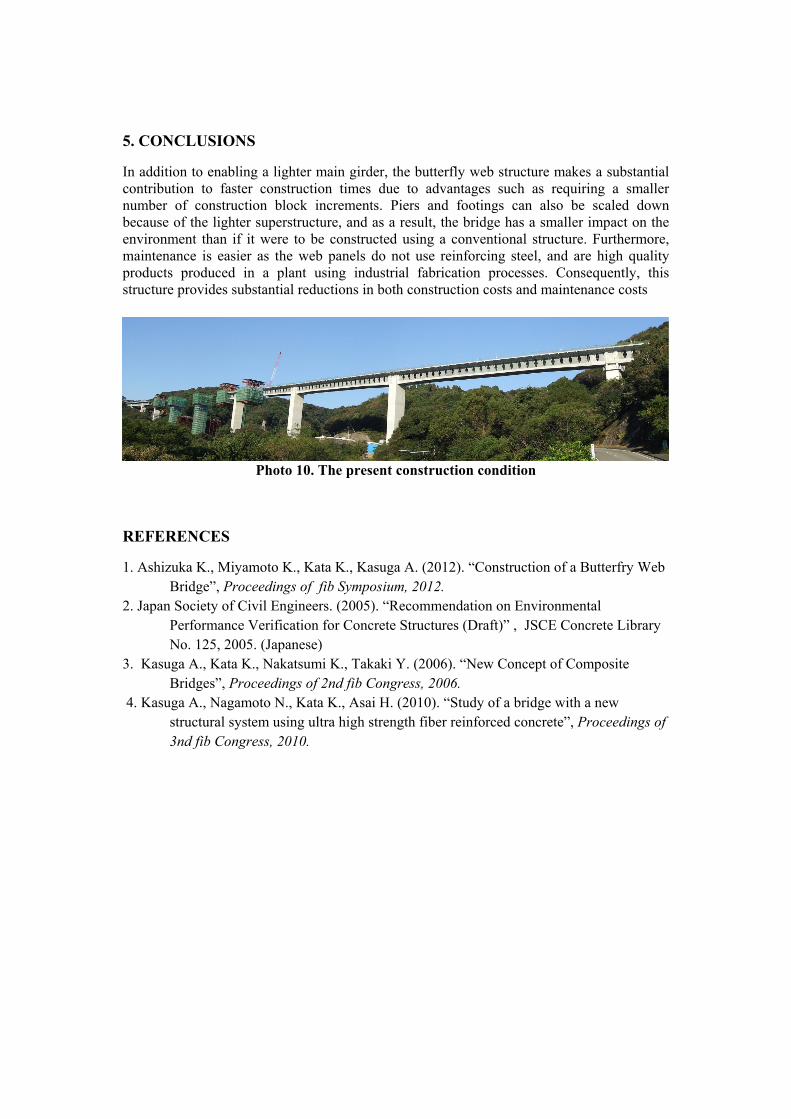
In addition to enabling a lighter main girder, the butterfly web structure makes a substantial contribution to faster construction times due to advantages such as requiring a smaller number of construction block increments. Piers and footings can also be scaled down because of the lighter superstructure, and as a result, the bridge has a smaller impact on the environment than if it were to be constructed using a conventional structure. Furthermore, maintenance is easier as the web panels do not use reinforcing steel, and are high quality products produced in a plant using industrial fabrication processes. Consequently, this structure provides substantial reductions in both construction costs and maintenance costs
Photo 10. The present construction condition
REFERENCES
1. Ashizuka K., Miyamoto K., Kata K., Kasuga A. (2012). “Construction of a Butterfry Web Bridge”, Proceedings of fib Symposium, 2012.
2. Japan Society of Civil Engineers. (2005). “Recommendation on Environmental Performance Verification for Concrete Structures (Draft)” , JSCE Concrete Library No. 125, 2005. (Japanese)
3. Kasuga A., Kata K., Nakatsumi K., Takaki Y. (2006). “New Concept of Composite Bridges”, Proceedings of 2nd fib Congress, 2006.
4. Kasuga A., Nagamoto N., Kata K., Asai H. (2010). “Study of a bridge with a new structural system using ultra high strength fiber reinforced concrete”, Proceedings of 3nd fib Congress, 2010.


![Section 18 Butterfly Valves - AAP Industries · BUTTERFLY VALVES [18] Wafer Butterfly Valve with Gear-Op Stainless Steel Wafer Butterfly Valve Wafer Butterfly Valve with Stainless](https://static.documents.pub/doc/80x56/60a1925cd0b68c353a5fc104/section-18-butterfly-valves-aap-industries-butterfly-valves-18-wafer-butterfly.jpg)


