50
Design and Construction of Formula SAE Composite Chassis 2010 Prepared by: Bhola Patel Design Engineer CADmantra Technologies Pvt.Ltd. CADmantra Technologies Pvt. Ltd.
| Date post: | 20-Jan-2017 |
| Category: |
Design |
| Upload: | cadmantra-technologies |
| View: | 378 times |
| Download: | 4 times |

Design and Construction of Formula SAE
Composite Chassis 2010 Prepared by:
Bhola Patel Design Engineer CADmantra Technologies Pvt.Ltd.
CADmantra Technologies Pvt. Ltd.

Design and Construction of Formula SAE Composite Chassis 2010
2010
Page | 2
CONTENTS 1. Introduction p3 2. Chassis Design p4 3. Material Selection p5 4. Composite Material Testing p7
4.1. Initial Material Testing p9 4.2. Secondary Material Testing p11
4.2.1. Varying Core Thickness p11 4.2.2. Varying Skin Thickness p13 4.2.3. Ribbon Direction p15
4.3. Final Material Testing p17 4.4. Steel Tube Testing p19 4.5. Perimeter Shear Strength Testing p20
5. Attachment Points p24 5.1. Insert Design p24 5.2. Insert Shear Testing p25 5.3. Insert Pull-out Testing p28 5.4. Insert Chassis Mounting p31
6. Chassis Construction p32 6.1. First Iteration p33 6.2. Second Iteration p34 6.3. Final Chassis Construction p36
6.3.1. CNC Routing p36 6.3.2. Adhesion of Folds p39 6.3.3. Front Roll Hoop Attachment p45 6.3.4. Cockpit Closeouts p46
7. Future Recommendations p48 8. Conclusion p49 9. References p50
Appendix A – Structural Equivalency Report
Design and Construction of Formula SAE Composite Chassis 2010
2010
Page | 3
1. Introduction For the 2010 F-SAE car, the decision was made to move from a tubular steel space-frame chassis to a composite monocoque chassis. Monocoque chassis can have many advantages over a steel construction with the potential for higher stiffness, greater safety for the driver, shorter build time and savings in weight, along with a greatly reduced need for external body work on the car. The method used to build the 2010 chassis was a “cut and fold” technique, which was applied to pre-fabricated aluminium honeycomb panels with carbon fibre skins.
While the decision was made to use these panels for the construction of the chassis in the early stages of the project, an extensive material testing program was carried out to determine a composite panel configuration which was suitable for F-SAE chassis construction. A method of attaching components to the chassis also had to be designed and tested as part of the project, and techniques for the construction of the chassis itself needed to be investigated.
This report describes the process of designing, testing and building the 2010 F-SAE chassis in detail.

Design and Construction of Formula SAE Composite Chassis 2010
2010
Page | 4
Figure 1: The 2010 F-SAE car at "rolling chassis" stage of construction
2. Chassis Design Rather than building a full monocoque chassis, it was decided that the 2010 chassis would consist of a composite monocoque “tub” forward of the main roll hoop, with a tubular steel frame rearwards of the main hoop incorporating a composite “rear plate” to tie the rear of the frame together and provide a mounting surface for the rear suspension and differential. The geometrical design of the 2010 chassis is based on dimensions of the previous year’s car with some modification to allow mounting of front lower A-Arms and the steering rack underneath the front of the chassis. The angles of the upper sides of the front of the chassis were also tailored to suit the angles which the rockers are required to be mounted at, allowing the rocker and damper assembly to be neatly mounted to the exterior of the front of the chassis.
The design of the chassis was modelled in Solidworks computer design software, in two parts, which were joined at the front roll hoop. The Solidworks model was then converted into a “sheet-metal” part of the same thickness of the honeycomb panels which allowed a

Design and Construction of Formula SAE Composite Chassis 2010
2010
Page | 5
flat pattern to be generated. This flat pattern was used for the routing of the composite panels so that an accurate copy of the part could be manufactured.
Computer modelling of the composite chassis is a great advantage as it allows for clearances for templates specified in the F-SAE rules (SAE 2010), and precise angles for suspension mounting to be checked and reviewed efficiently before manufacture of the chassis begins.
3. Material Selection It was decided to use a carbon fibre skinned aluminium honeycomb sandwich panel for the construction of the composite chassis because of the high strength and stiffness of the composite structure in relation to its weight. Sandwich panels are able to have high levels of strength and stiffness in relation to their weight because most of the mass is concentrated in the skins of the panel, which take the majority of the loads in a bending situation. Figure 2 shows the construction of a honeycomb panel.
Figure 2: A Honeycomb Panel
For any material, the peak compressive and tensile forces generated in a bending situation are concentrated at the surfaces of the material. Honeycomb panels exploit this characteristic and provide a light weight filler material between the panel skins. The thicker this core material, the more stiff a panel becomes (see Figure 3: http://www.hexcel.com/NR/rdonlyres/599A3453-316D-46D6-9AEE-C337D8B547CA/0/HexwebAttributesandProperties.pdf cited on the 1/11/2010 ).

Design and Construction of Formula SAE Composite Chassis 2010
2010
Page | 6
Figure 3: A Table showing relative stiffness vs core thickness
Although increasing core thickness increases adds stiffness to the material, the skin material and thickness also determines the stiffness and strength of the sandwich panel. Carbon fibre was chosen for the skin material in the 2010 chassis’ panels because of the material’s high strength to weight ratio, which is much higher than aluminium or steel. Carbon fibre was also chosen to be used instead of a standard aluminium skin because the number and orientation of plies of carbon fibre can be tailored to suit the chassis construction.
The decision was made to use pre-fabricated composite panels for the composite monocoque chassis, “cut and folded” to form the desired shape, rather than manufacturing a moulded composite monocoque for a variety of reasons. These reasons include; ease of manufacture, reliability of cure process, and reduced cost of manufacture.
Perhaps the most important reason for use of pre-fabricated panels is the reliability of the cure process of the composite material. Because the flat panels are made using a heat press using a process that has been perfected over years of manufacturing, the panels are guaranteed to have a more even and reliable skin to core adhesion and structural integrity than a chassis which is “vacuum bagged”. Chassis, or other composite components, especially involving honeycomb, which are vacuum bagged in a mould are liable to a variety of defects which compromise the structural integrity of the part. These defects include poor skin to core adhesion, surface pitting, poor bonding between layers of fibre, and bridging of the mould.

Design and Construction of Formula SAE Composite Chassis 2010
2010
Page | 7
Another important advantage of the “cut and fold” technique using pre-fabricated panels is the ease of manufacture. Because a “cut and folded” structure requires no moulds for its construction and can be made using only basic cutting tools, the construction of a chassis is much simpler and easier than a moulded composite chassis. Being easy to manufacture also cuts the build time down allowing more man-hours to be focussed in other areas.
4. Composite Material Testing To comply with Formula-SAE rules (SAE 2010), the composite material used for construction of the chassis needs to meet various strength and stiffness requirements. The yield and ultimate strengths of a section of panel 200mm wide by 500mm long must be greater than or equal to the yield and ultimate strengths of two baseline steel side impact tubes, and the stiffness must be greater than one baseline steel side impact tube in a three point bending test configuration.
To perform these tests, a three point bending test jig was constructed to be compatible with the Instron 5569 Universal material testing machine located in ECU’s material testing laboratory (see Figure 4). Due to size constraints of the machine, specimens 100mm wide and 350mm long were tested and calculations were performed to compare the results of these tests to requirements in the F-SAE rules (SAE 2010).
To obtain meaningful results, it was necessary to place 30mm wide strips of steel (with a radius on the edges) at the loading points of the three point bending test jig. These strips of steel are to help distribute the load evenly into the panel so that localised failure, due to crushing of the honeycomb core, does not occur. Premature failures of this nature produce inaccurate results because the panel itself is not being loaded, only localised failures are induced.

Design and Construction of Formula SAE Composite Chassis 2010
2010
Page | 8
Figure 4: Three Point Testing Jig
To compare the three point test results to baseline steel side impact tubes, the yield and ultimate strengths and stiffness of steel tube were determined through calculations. The F-SAE rules (SAE 2010) do not specify a particular steel alloy for steel tubing so properties of AISI 1020 steel are used. The values are tabulated below.
Tensile Strength 365 MPa
Yield Strength 305 MPa
Modulus of Elasticity 200 GPa Table 1: Steel properties
The calculations for a round tube 25.4mm x 1.60mm as approved in the F-SAE rules (SAE 2010) for a baseline side impact tube are shown below:
( )

Design and Construction of Formula SAE Composite Chassis 2010
2010
Page | 9
Failure in bending is given by the following equation:
Calculating for one baseline side impact tube:
Yield Failure 3.27 kN Ultimate Failure 3.91 kN
Table 2: Side Impact Single Tube Failure
Multiplying these forces by 2 provides the force required to bend two baseline side impact tubes:
Yield Failure 6.54 kN Ultimate Failure 7.82 kN
Table 3: side impact two tube failure
For a three point bend test the maximum deflection is given by the following equation:
Rearranging:
EI becomes a measure of stiffness for the tube, which can be determined experimentally for the panel.
With the strength and stiffness targets for the composite panels calculated, a series of physical tests were carried out on composite panels to determine the ideal layup.
4.1 Initial Material Testing To begin with, a carbon fibre skinned aluminium honeycomb panel was manufactured for testing using a single ply of 200gsm twill weave carbon fibre pre-preg adhered either side of a 20mm thick 1/4” cell honeycomb core by a 250gsm ply of glass fibre pre-preg. This ply of glass fibre was recommended by the manufacturer to be used because of its high resin

Design and Construction of Formula SAE Composite Chassis 2010
2010
Page | 10
content which would bond well to the core and also the glass fibre was stocked by the manufacturer.
Two series of tests were carried out on this panel; the first with the fibres of the carbon fibre weave aligned along the length of the test piece(see Figure 5), and the second with the carbon fibres aligned at 45° to the length of the samples. The glass fibres are aligned at 45° to the carbon fibres (Figure 6).
Figure 5: Graph showing three point test data for carbon aligned at 0 degrees to the length of the test piece
Figure 6: Graph of test data for carbon aligned at 45 degrees
These two series of test show that; a) the samples with the carbon fibres aligned with the length of the test piece perform better in terms of strength and stiffness than the samples with the carbon fibres aligned at 45° to the test piece, and; b) the mode of failure is brittle in
0
500
1000
1500
2000
2500
3000
3500
4000
0 2 4 6 8 10
Load
- N
Displacement - mm
Test Series 1 (carbon @ 0°)
0
500
1000
1500
2000
2500
3000
3500
4000
0 2 4 6 8 10
Load
- N
Displacement - mm
Test Series 2 (carbon @ 45°)

Design and Construction of Formula SAE Composite Chassis 2010
2010
Page | 11
nature and there is little yielding of the composite material before ultimate failure. For the purpose of comparing the yield strength of the composite material to the steel tube, yield strength is assumed to be equal to ultimate strength.
The test series which has the carbon fibres aligned along the length of the sample had an ultimate/yield strength of about 3.6kN, and an EI (buckling modulus, a measure of stiffness) of 2.5x10⁸ Nmm2. The EI was calculated using the following equation between loads of 0.5kN to 2kN to eliminate the early deflection of the testing jigs. These results will be multiplied by two to simulate a 200mm wide panel as required in the rules (SAE 2010).
The yield and ultimate strengths needed to be greater than 6.54kN and 7.82kN respectively to be stronger than the two steel side impact tubes. The EI of the panel had to be greater than 1.7 x 10⁹ Nmm2 to be stiffer than the steel tube. Table 4 below shows the properties of the composite panel relative to the properties required by the F-SAE rules (SAE 2010).
Yield Strength Ultimate Strength EI Composite Panel 7.2kN 7.2kN 5.0 x 10⁸ Nmm2 Required by rules 6.54kN 7.82kN 1.7 x 10⁹ Nmm2
Table 4: Composite panel vs baseline steel properties
These results show that the panel needs to be stronger in ultimate strength, and also over two times stiffer.
4.2 Secondary Material Testing After testing of the initial panel, which indicated that the composite panel needed to be significantly stiffer, a secondary series of tests was carried out to determine experimentally the effects of increasing skin thickness and core thickness. This series of tests involved three point flexure tests of a variety of aluminium skinned panels of different core thickness and skin thickness. These tests also investigated the effect of the ribbon direction of the honeycomb core on the strength and stiffness of the panels.
4.2.1 Varying Core Thickness
Three point tests were carried out on aluminium skinned panels with thicknesses of 10mm, 20mm and 50mm each with 0.5mm thick aluminium skins. These tests were intended to experimentally show the relationship between panel thickness and stiffness and strength. Graphs showing the results of these tests are shown below in Figures 7 and 8.

Design and Construction of Formula SAE Composite Chassis 2010
2010
Page | 12
Figure 7: Graphs of three point bend test results for 10mm, 20mm, 50mm thick 0.5mm aluminium skinned panels
0
200
400
600
800
1000
1200
1400
1600
0 2 4 6 8 10 12 14
10mm 0.5/0.5
#1
#2 (defect)
#3
0
500
1000
1500
2000
2500
3000
0 5 10 15
20mm 0.5/0.5
#1
#2 (93mm)
0
1000
2000
3000
4000
5000
6000
-1 1 3 5 7 9 11 13 15
50mm 0.5/0.5
#1
#2

Design and Construction of Formula SAE Composite Chassis 2010
2010
Page | 13
Figure 8: Comparison of stiffness and ultimate strength with varying core thickness
It can be seen from these results that increasing the panel thickness significantly increases the stiffness and strength of the panel.
4.2.2 Varying Skin Thickness
A second series of tests were carried out on aluminium skinned panels to investigate the effect of skin thickness on stiffness and strength. 20mm thick panels were tested with 0.3mm, 0.5mm and 1.0mm thick skins (see Figure 9). Increasing skin thickness seemed to have no significant effect on strength of the panel, but stiffness increased noticably.
010002000300040005000600070008000
0 10 20 30 40 50 60
Stiff
ness
N/m
m
Core thickness
Stiffness @ 1000N with varying core thickness
0
1000
2000
3000
4000
5000
6000
0 10 20 30 40 50 60
Failu
re L
oad
- N
Core thickness - mm
Ultimate strength with varying core thickness

Design and Construction of Formula SAE Composite Chassis 2010
2010
Page | 14
Figure 9: Graphs of three point test data from 20mm panels with 0.3mm, 0.5mm, 1.0mm aluminium skins
0
500
1000
1500
2000
2500
-1 1 3 5 7 9 11 13 15
20mm 0.3/0.3
#1
#2
#3
0
500
1000
1500
2000
2500
3000
0 5 10 15
20mm 0.5/0.5
#1
#2 (93mm)
0
500
1000
1500
2000
2500
3000
-1 1 3 5 7 9 11 13 15
20mm 1.0/1.0
#2
#1

Design and Construction of Formula SAE Composite Chassis 2010
2010
Page | 15
Figure 10: Comparison of ultimate strength and stiffness with skin thickness
The failure to see an increase in strength with increasing skin thickness is likely due to localised failure of the panel at the loading points of the three point test jig.
4.2.3 Ribbon Direction
Aluminium honeycomb is made up of ribbons of aluminium foil glued together at intervals and expanded to form hexagonal voids in the material (see Figure 11: http://www.hexcel.com/NR/rdonlyres/599A3453-316D-46D6-9AEE-C337D8B547CA/0/HexwebAttributesandProperties.pdf cited on the 1/11/2010). The direction that these continuous ribbons run, have an effect on the properties of the honeycomb in different orientations. It can be expected that the honeycomb will be stronger and stiffer in the direction that the ribbons run.
0
500
1000
1500
2000
2500
3000
0 0.2 0.4 0.6 0.8 1 1.2
Ulti
mat
e lo
ad -
N
Skin thickness - mm
Ultimate failure load with increasing skin thickness
0
0.5
1
1.5
2
2.5
0 0.2 0.4 0.6 0.8 1 1.2
Defle
ctio
n - m
m
Skin Thickness - mm
Deflection with increasing skin thickness

Design and Construction of Formula SAE Composite Chassis 2010
2010
Page | 16
Figure 11: Diagram of aluminium honeycomb manufacture
The standard procedure for flexure testing honeycomb panels is to orient the ribbons of honeycomb across the test specimen in the weakest orientation. The F-SAE rules (SAE 2010) however do not specify this test condition, and the orientation of the honeycomb ribbons in the chassis itself will be along the length of the car so there is no reason not to test the panels in the strongest orientation.
Three point tests were performed on 30mm (0.5mm skins) panels to investigate how much this ribbon orientation affects the stiffness and strength of the panels.
Figure 12: Graph of three point tests on samples with different honeycomb ribbon orientation
0
1000
2000
3000
4000
5000
0 1 2 3 4 5 6
Load
(N)
Deflection (mm)
Effect of Ribbon Orientation 3-Point Tests
Long Ribbon 1
Long Ribbon 2
Long Ribbon 3
Short Ribbon 1
Short Ribbon 2
Short Ribbon 3

Design and Construction of Formula SAE Composite Chassis 2010
2010
Page | 17
As displayed in the above graph (Figure 12) the panel specimens with a “long ribbon” (the ribbon running along the length of the test sample) are significantly stronger and stiffer than the “short ribbon” samples.
4.3 Final Material Testing Through the knowledge gained from the previous three point test series, a carbon fibre skinned test panel was manufactured with a 30mm thick aluminium honeycomb core and a variety of different combinations of ply numbers and orientations of carbon fibre pre-preg. Two methods of adhering the skins to the core were also trialled with a glass fibre pre-preg used for some samples and an epoxy film adhesive used as an alternative.
Due to the number of different combinations of ply orientations of the different test samples, a nomenclature system was developed to number the samples and to easily recognise the layup of the panels. For example “G90-C90-2C45” means one ply of glass fibre aligned at 90° to the test piece, one ply of carbon fibre aligned at 90°, and two plies of carbon fibre aligned at 45° to the length of the test piece, either side of the panel.
The results from the testing of these panels are displayed in graphical form (Figure 13) below;
Figure 13: Comparison of three point bend test results with different carbon fibre ply orientations
The results of the bending tests show that increasing the number of plies of carbon fibre aligned at 90° to the length of the test panel improves stiffness, while the ultimate strength seems to decrease. This decrease in ultimate strength is believed to be due to the load
010002000300040005000600070008000
1 2 3 4
Load
(N)
Deflection (mm)
3 Point Bend Tests of 30mm Core With Carbon Only Skins
2C90 C45 (1)
2C90 C45 (2)
3C90 (1)
3C90 (2)
C90 2C45 (1)
C90 2C45 (2)
4C90 (1)
4C90 (2)

Design and Construction of Formula SAE Composite Chassis 2010
2010
Page | 18
applied to the panel in the three point tests being more concentrated in the middle of the panel at the loading point as the panel stiffness increases. This concentration of the load results in localised crushing of the core and premature failure of the panel.
The above results only show the combinations of carbon fibre plies adhered to the core with an epoxy film adhesive. Testing of panels with the carbon fibre adhered to the core with glass fibre show a further increase in stiffness when the glass fibres are aligned at 90° to the length of the test panel (see Figure 14).
Figure 14: Comparison of three point test results with different skin adhesion methods
Although the panels with glass fibre included in the lay-up were slightly stiffer, they were also heavier which is why the epoxy film adhesive was chosen for use in the chassis. The lay-up chosen for construction of the 2010 F-SAE chassis was “2C90-C45”. This lay-up was chosen because it satisfies the requirements of the rules (SAE 2010), is relatively lightweight, and also provides torsional stiffness to the chassis with the ply of carbon fibre aligned at 45°.
The composite panel chosen for use in the F-SAE chassis out-performs the baseline steel tube in both strength and stiffness (see Table 5).
Ultimate/Yield Strength EI (stiffness) Steel Tube (Rules) 7,820N 1.7 x 10⁹ Nmm2 Composite Panel (2C90-C45) 14,000N 2.12 x 10⁹ Nmm2
Table 5: Table showing properties of composite panels vs calculated baseline steel tube properties
010002000300040005000600070008000
1 1.5 2 2.5 3 3.5 4
Load
(N)
Deflection (mm)
3 Point Bend Tests: Glass Fibre vs Film Adhesive
G45-2C90-C45 (1)
G45-2C90-C45 (2)
G90-2C90-C45 (1)
G90-2C90-C45 (2)
2C90-C45 (1)
2C90 C45 (2)

Design and Construction of Formula SAE Composite Chassis 2010
2010
Page | 19
4.4 Steel Tube Testing In order to experimentally determine the strength and stiffness of steel tube, a series of three point bending tests were carried out on steel tubing for comparison to calculated values. These tests were performed under the same testing conditions as the three point composite tests to provide consistency across the results and to determine a margin of error which is present in the testing facilities (see Figure 15).
Due to availability, a 25.4mm x 1.4mm round steel tube was tested rather than the standard side impact tube. This test was not designed for a direct comparison to the composite monocoque structure, but rather to prove that the calculated properties of steel tube will not be seen in testing due to deflection of the jigs and connections.
Figure 15: Steel Tube 3 point bend test

Design and Construction of Formula SAE Composite Chassis 2010
2010
Page | 20
Table 6 displays the results of a typical three point bending test on a (25.4mm x 1.4mm) steel tube and the corresponding calculated properties.
Stiffness Ultimate Load Yield Load EI Measured Properties 2686 N/mm 4250 N 3000 N 0.8 x 10⁹Nmm2 Calculated Properties
4685 N/mm 3507 N 2930 N 1.58 x 10⁹Nmm2
Table 6: Comparison of measured and calculated
These results show that the yield and ultimate loads are both slightly underestimated by the calculations because the calculations are based on properties of a softer grade of steel. The stiffness, however, is overestimated by a factor of more than 1.7. This lack of stiffness seen in the physical test of the tube is due to deflection in the testing apparatus, and localised deflection of the tube around the loading points. A second series of three point bending tests were performed to demonstrate the overestimation of stiffness by calculation. These tests were carried out on 4130 High strength steel tube with dimensions of (25.4mm x 1.2mm) and (25.4mm x 2.4mm).
Calculated Stiffness (N/mm)
Measure d
Stiffness (N/mm)
% of Calculated
EI Calculated (Nmm2)
EI Measured
(Nmm2)
25.4mm x 1.2mm Tube
4113 3000 73 1.34 x 10⁹ 0.98 x 10⁹
25.4mm x 2.4mm Tube
7122 5602 79 2.32 x 10⁹ 1.82 x 10⁹
Table 7: comparison of measured and calculated II
These results (Table 7) clearly show that the calculated stiffness for a given steel tube cannot be used to compare to the composite laminate. The calculations consistently overestimate the stiffness of the steel tube when compared to experimental results.
4.5 Perimeter Shear Strength To comply with Formula SAE rules (SAE 2010), a perimeter shear test was required to test the anti-intrusion protection provided by the composite material. This test involved forcing

Design and Construction of Formula SAE Composite Chassis 2010
2010
Page | 21
a 1” diameter object through the skin of the panel and measuring the force required to break through. The rules (SAE 2010) specify that the perimeter shear strength must at least 7.5kN in the side impact zone of the chassis. Figure 16 shows the perimeter testing apparatus.
Figure 16: Perimeter Shear Test apparatus
Testing of the carbon fibre skinned honeycomb panels used in the chassis construction revealed that the perimeter shear strength, for the 1” diameter object, is just over 4kN (see Figure 17). This performance is significantly less than the required 7.5kN so a method of spreading the load from the 1” diameter object needed to be developed.

Design and Construction of Formula SAE Composite Chassis 2010
2010
Page | 22
Figure 17: Initial perimeter shear test results
A second series of perimeter shear tests were carried out with a variety of different coatings applied to the outside skin of the carbon fibre panels. These included a thin aluminium sheet (0.3mm) glued on with epoxy resin, an aluminium sheet glued with a thermo-setting plastic glue, and a wet laid –up ply of Kevlar. The results of these tests are displayed below (Figures 18, 19 and 20).
Figure 18: Perimeter shear test with 0.3mm aluminium sheet added to the lay-up, glued with epoxy resin
0
1000
2000
3000
4000
5000
2 2.5 3 3.5 4 4.5 5 5.5 6 6.5
Load
(N)
Deflection (mm)
Perimeter Shear Strength (Carbon Fibre Skins)
010002000300040005000600070008000
0 2 4 6 8 10 12
Load
(N)
Deflection (mm)
Perimeter Shear Test with 0.3 aluminium (epoxy glue)

Design and Construction of Formula SAE Composite Chassis 2010
2010
Page | 23
Figure 19: Perimeter shear test with 0.3mm aluminium sheet, glued with thermo-setting plastic glue
Figure 20: Perimeter shear test with wet laid-up Kevlar
It can be seen from the results of the first perimeter shear test with the epoxy resin gluing the 0.3mm aluminium sheet to the panel failed prematurely from the 7.5kN requirement. From observation of the tests, it was clear that the panel failed early because the adhesion of the aluminium to the carbon fibre also failed early. This early failure can be seen as “steps” in the load vs deflection graph.
A second test was performed on the same aluminium sheet as the previous test glued to the carbon fibre with a thermo-setting plastic adhesive. This test showed that the plastic adhesive far outperformed the epoxy resin and allowed the panel to withstand up to around
0
2000
4000
6000
8000
10000
12000
0 2 4 6 8 10 12
Load
(N)
Deflection (mm)
Perimeter shear Test with 0.3mm aluminium (plastic glue)
02000400060008000
10000120001400016000
0 2 4 6 8 10 12 14 16
Load
(N)
Deflection (mm)
Perimeter Shear Test with Kevlar

Design and Construction of Formula SAE Composite Chassis 2010
2010
Page | 24
9.5kN. The Kevlar coated panels also performed very well and failed at around 13.5kN, well exceeding the requirements of the F-SAE rules (SAE 2010).
The coating decided on for the actual construction of the side impact zone of the 2010 ECU chassis was the 0.3mm aluminium sheet. This sheet was glued to the chassis using a high performance polyurethane adhesive (Sikaflex™). The thermosetting adhesive was not used due to concerns about heating the honeycomb chassis to the temperatures required to cure the adhesive.
Although it performed well, Kevlar was not used as a coating as the fabric that was tested was heavier than the aluminium coating. In future years however, further testing may reveal that a finer weave of Kevlar may be preferable to the aluminium sheet.
5. Attachment Points
5.1 Insert Design To provide a secure method of mounting components to the composite monocoque, inserts are used to transfer loads to the chassis which prevent crushing of the core and efficient transfer of loads to the skins of the composite sandwich structure.
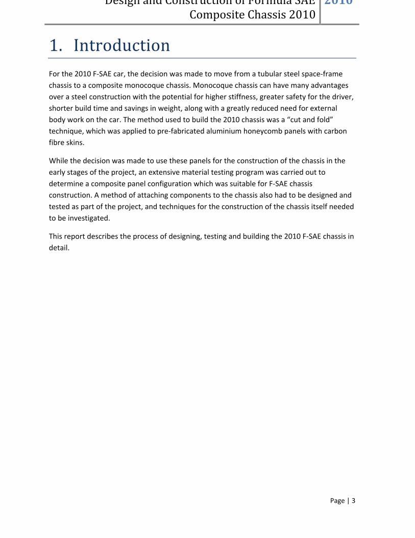
These inserts, or “ferrules”, are machined from L168 Aluminium which is an alloy used in Aerospace, Defence and High Technology applications. Inserts were then treated by chromic acid anodising for protection against corrosion, which was a concern because of the proximity to carbon fibre which could result in galvanic corrosion. The inserts illustrated below (Figure 21) are set into the panel with epoxy resin which is injected into the cavity around the knurled part of the insert. The resin is injected through the holes machined into the insert.
Design and Construction of Formula SAE Composite Chassis 2010
2010
Page | 25
Figure 21: Insert Design
5.2 Insert Shear Testing Physical tests were performed on inserts so that structural equivalency could be proven and the number of these inserts required for attachment of various components could be determined. Testing was carried out on an Instron 5569 material testing machine using a custom made jig for holding the test pieces. The machine then pulls apart at a constant strain rate of 0.1mm/second and a read-out of the forces induced is provided. Photographs of the test procedure and test pieces are included below (Figures 22 and 23). The ultimate failure load of these inserts in a shear was tested at 16.5kN.

Design and Construction of Formula SAE Composite Chassis 2010
2010
Page | 26
Figure 22 : Insert shear test jig

Design and Construction of Formula SAE Composite Chassis 2010
2010
Page | 27
Figure 23 : Insert Shear Test Piece
Design and Construction of Formula SAE Composite Chassis 2010
2010
Page | 28
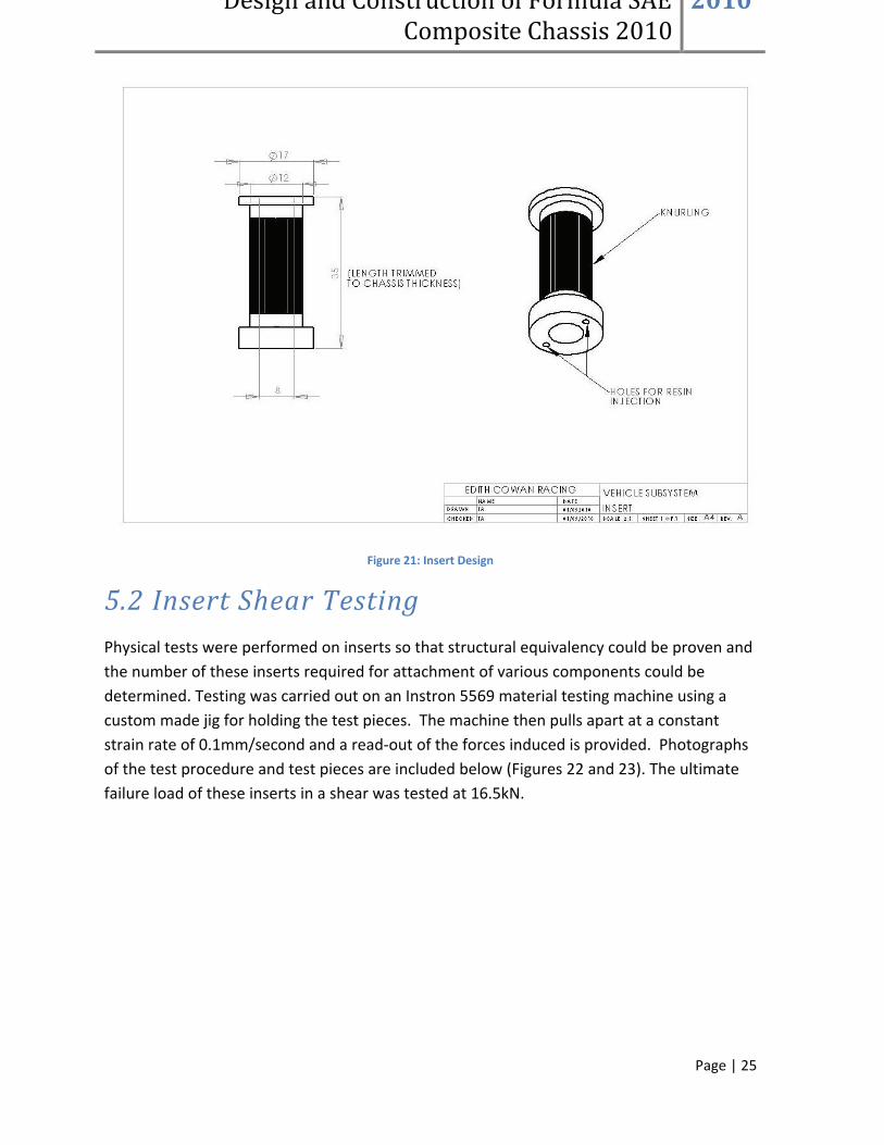
5.3 Insert Pull-out Testing A second series of tests was carried out to determine the “pull-out” strength of the insert design. This test is designed to discover the force required for the insert to be pulled through the composite structure with a 50mmx1mm steel washer. Pictures of the test apparatus and test specimens, along with a graph of a typical test result are included below Figures 24 – 28).
Figure 24: insert pullout test
Design and Construction of Formula SAE Composite Chassis 2010
2010
Page | 29
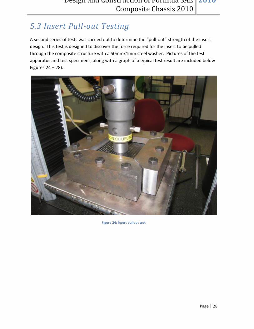
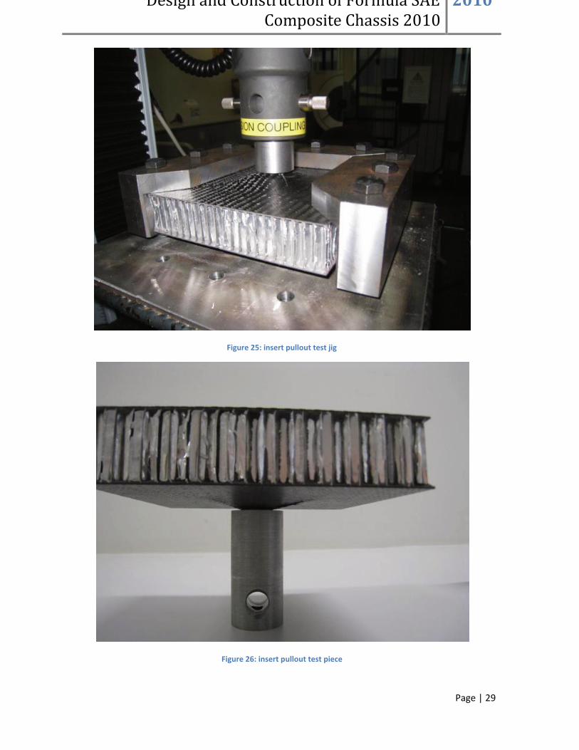
Figure 25: insert pullout test jig
Figure 26: insert pullout test piece

Design and Construction of Formula SAE Composite Chassis 2010
2010
Page | 30
Figure 27: Insert pullout test piece
Figure 28: Insert pullout test graph
0
2000
4000
6000
8000
10000
12000
0 5 10 15 20 25 30
Load
(N)
Tensile Extension (mm)
Ferrule Pull-out Test 1 With 50mm Washer

Design and Construction of Formula SAE Composite Chassis 2010
2010
Page | 31
From the results of this test series, it can be seen that this is the weakest direction of loading for an attachment point. The peak load sustained in this direction was just over 10kN, but the insert continued to hold a load of over six kilo-Newtons for a further 10mm of deflection indicating that a massive amount of energy can be absorbed by the pick-up point.
5.4 Insert Chassis Mounting An issue that was encountered during the construction of the 2010 chassis was the drilling of accurate holes for mounting of inserts. These holes needed to be perfectly perpendicular to the surface of the chassis for the inserts to be installed correctly. The solution to this problem was the construction of an improvised “drill press” attachment for a hand held cordless drill (see Figure 29).
Figure 29: Drill press rig with cordless drill installed
Due to the varying total thickness of the chassis, a result of varying amounts of extra layers of wet laid-up carbon fibre, inserts needed to be trimmed to a size specific to its location. This was achieved by milling the insert down while being held by a custom jig. Once these inserts were correctly sized, they were then cleaned with acetone and pressed into the

Design and Construction of Formula SAE Composite Chassis 2010
2010
Page | 32
holes at the required locations. The inserts were then set into place by injecting epoxy resin into the holes in the top of the inserts which were designed for this purpose.
6. Chassis Construction The construction of the 2010 F-SAE chassis is based on the technique of “cutting and folding” of flat honeycomb panels. “Cutting and folding” honeycomb panels involves the removal of a strip of material from the inside of the bend to be formed. The panel is then folded over to form the desired angle of bend and a reinforcing strip of material is added to stiffen the bend (see Figure 30).
Figure 30: The "cut and fold" process
The size of the strip of material required to be removed from the skin of panel is proportional to the size of the angle of the desired bend, and the thickness of the panel. The width of the slot can be determined using the following equation.
Where Ѳ=angle of bend, S=slot width, and T=thickness of panel.
During the course of 2010, two mock-up chassis were built as well as the final chassis using the “cut and fold” technique. The building of these chassis is discussed in more detail in the following sections of this report.

Design and Construction of Formula SAE Composite Chassis 2010
2010
Page | 33
Figure 31: The three monocoque chassis iterations
6.1 First Iteration Early in 2010, before any composite material testing was carried out, the first of two mock chassis was constructed. This chassis was made from aluminium panels and was made as a “proof of concept” and was used to find out how well the “cut and fold” technique worked in chassis construction. The chassis was hand routed and the inside of the folds were held together by strips of aluminium sheet glued into place.

Design and Construction of Formula SAE Composite Chassis 2010
2010
Page | 34
Figure 32: First chassis iteration
While this chassis is not made from materials that would stand up to use as a chassis, the mock-up provided encouragement for the team and led to further investigation into materials and manufacturing techniques. This mock-up proved that a chassis could be constructed in this way in a short space of time, with this first iteration being completed within two weeks (see Figure 32).
6.2 Second Iteration After deciding to build the chassis from carbon fibre skinned panels, a second mock-chassis was built to develop and test techniques to join this type of material together and to secure the insides of folds. A technique also had to be developed to secure the front roll hoop within the structure of the chassis.

Design and Construction of Formula SAE Composite Chassis 2010
2010
Page | 35
Figure 33: Second chassis iteration
This second iteration mock chassis was constructed from 30mm thick aluminium skinned panels (which are much cheaper than carbon fibre). The aluminium skinned composite panels were CNC routed which provided a greater degree of dimensional accuracy over the chassis and proved to be a quicker, more efficient method of cutting the shape of the flat pattern for the chassis.
Before the construction of the second mock chassis began, it was decided that carbon fibre skinned panels would be used for the final chassis. Techniques were therefore used to build this mock-up that suited a carbon fibre structure. Rather than using strips of aluminium for reinforcing the insides of the folds, multiple plies of wet laid-up carbon fibre were used over an epoxy filler used to round off the corners of the folds.
The fillet of epoxy filler, which consists of epoxy resin mixed with “Q-Cell” (glass micro-balloons), which was spread into place using a small piece of steel tube which has the desired radius for the fillet. The radius for the fillet was around 20mm. For this mock-up, the wet laid-up carbon fibre was pressed into place over the filler with plastic bags filled with sand, which conforms to the profile of the inside of the fold and holds the fibres down while curing.
The construction of this mock-up proved useful for practicing and developing techniques used to reinforce folded joins and also served as a test for the process of CNC routing of the flat pattern of the chassis. This mock-up also proved useful for the purpose of test fitting components such as dampers, fuel tank, rear sub-frame, and other parts before fitting to the final chassis (see Figure 33).

Design and Construction of Formula SAE Composite Chassis 2010
2010
Page | 36
6.3 Final Chassis Construction
Figure 34: Final monocoque chassis
6.3.1 CNC Routing
The preferred method decided upon for cutting out of the flat pattern of the chassis from carbon fibre skinned honeycomb panels is CNC routing. This method proved to be the fastest, most accurate technique of cutting the basic flat shape of the chassis and the slots required for the various folds in the chassis. CNC routing is also a relatively cost effective method of cutting the panels with a quote of $100 from one CNC routing company, however the chassis was routed free of charge this year by a sponsor.
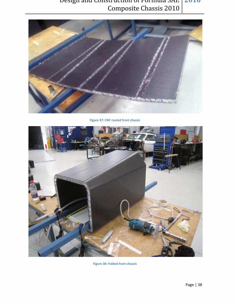
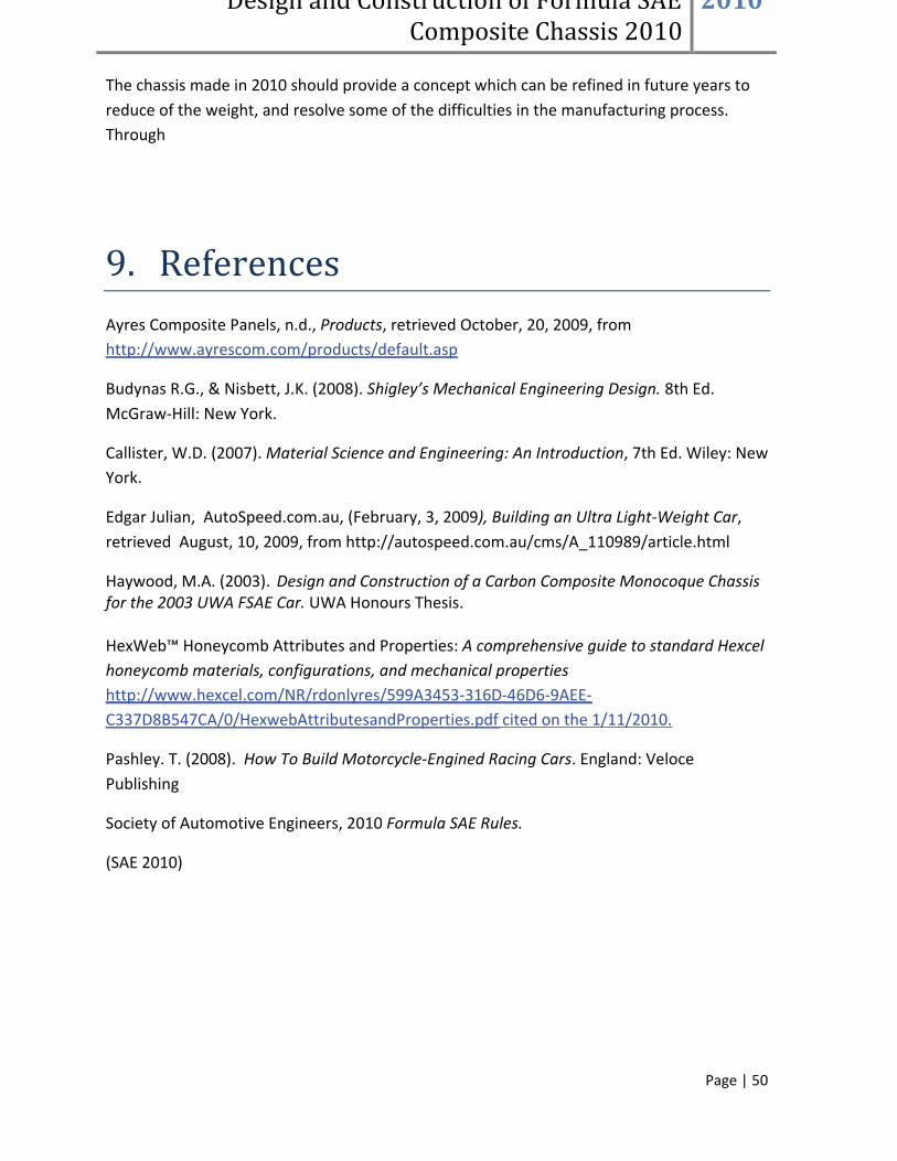
To get the panels routed, a .dxf electronic drawing needed to be produced. This was easily produced from a Solidworks drawing of the flat chassis pattern (Figures 35 and 36). This flat pattern was produced from creating a “sheet metal” part from a Solidworks solid body (Figures 37 and 38).

Design and Construction of Formula SAE Composite Chassis 2010
2010
Page | 37
Figure 35: Solidworks front chassis model
Figure 36: .DXF drawing of front chassis
Design and Construction of Formula SAE Composite Chassis 2010
2010
Page | 38
Figure 37: CNC routed front chassis
Figure 38: Folded front chassis

Design and Construction of Formula SAE Composite Chassis 2010
2010
Page | 39
6.3.2 Adhesion of Folds
As the chassis was being folded up, filler needed to be applied to the insides of the folds to provide initial stiffening of the bends and to form a corner radius which the carbon fibre stiffener will readily conform to. The filler used for the final chassis construction was a cotton “micro-fibre blend” which is added to epoxy resin. This filler is stronger and less brittle than the “Q-Cell” filler used in the second mock-up chassis, although of a higher density. This filler was applied using a piece of steel tube as a tool to spread the filler to the required radius.
Figure 39: Folded, un-reinforced rear chassis

Design and Construction of Formula SAE Composite Chassis 2010
2010
Page | 40
Figure 40: Epoxy filler application

Design and Construction of Formula SAE Composite Chassis 2010
2010
Page | 41
Figure 41: Spreading epoxy filler

Design and Construction of Formula SAE Composite Chassis 2010
2010
Page | 42
Figure 42: Completed epoxy filler fillet
After this filler was allowed to set, a two strips of 200gsm carbon fibre aligned at 90° to the fold and one layer of carbon fibre aligned at 45° to the fold were applied to the inside of the bend. These strips were approximately 140mm wide, and the fibre alignment corresponds approximately to the alignment of the fibres in the chassis panels. These panels were then pressed into place using a “vacuum bag” technique. This process involves a sealed bag being constructed using a plastic film, which the air is drawn out of using a vacuum pump. This allows atmospheric pressure to press against the bag to press the fibres down during the cure process. A peel ply is used in the lay-up to soak up excess resin and to leave a seamless finish with the chassis composite panels.

Design and Construction of Formula SAE Composite Chassis 2010
2010
Page | 43
Figure 43: Diagram of carbon fibre wet lay-up of joins using a vacuum bag
Figure 44: Vacuum bagging front chassis folds

Design and Construction of Formula SAE Composite Chassis 2010
2010
Page | 44
Minimal jigging was necessary to form the angles of the folds. However, care needed to be taken in ensuring that the angles formed were correct. This was achieved through clamping the panel to a table and securing the angles of the folds with a wooden jig and reinforced tape. For a “one off” production this method worked well, but perhaps a more secure jig would be required if a longer production run was ever produced of the chassis.
Figure 45: Folding rear of chassis with the aid of a wooden jig

Design and Construction of Formula SAE Composite Chassis 2010
2010
Page | 45
Figure 46: Folded rear chassis
6.3.3 Front Roll Hoop Attachment
To comply with the 2010 F-SAE rules (SAE 2010) a front roll hoop is required to be included in the composite monocoque structure. This roll hoop consists of a continuous section of 25.4mm x 2.4mm round steel tubing which extends from the lowest point on the chassis within the plane of the hoop, up, over and down to the lowest point on the opposite side of the chassis. The hoop is situated in the vicinity of the steering wheel and is between the front and rear sections of the composite monocoque.
This roll hoop is attached by being included as an integral part of the monocoque layup. The hoop was first adhered to the foot well section of the chassis using a filler consisting of epoxy resin mixed with a cotton micro-fibre blend, the same filler used to fill the inside of the chassis folds. To make the hoop fit between the layers of carbon fibre in the chassis panels, some of the honeycomb core needed to be removed. After joining the hoop to the front chassis section, the two halves of the chassis were brought together and glued together using more epoxy filler.

Design and Construction of Formula SAE Composite Chassis 2010
2010
Page | 46
Figure 47: Front roll hoop glued into front chassis before joining front to rear
When the two halves of the chassis were joined together, strips of carbon fibre were wet laid-up over both sides of the join and vacuum bagged while curing. These strips of carbon fibre were wider than the strips used to reinforce the folds of the chassis (approximately 200mm) and four plies were used rather than three. This was because this join between the two halves of the chassis is a critical area and failure of this join would be catastrophic. After the join between the two halves of the chassis was completed, layers of carbon fibre were wrapped over the exposed section at the top of the hoop to make it a fully integrated part of the chassis structure.
6.3.4 Cockpit Closeouts
Edges of the composite panels which are untreated and left as exposed aluminium honeycomb are unsightly and leave sharp edges which are easily damaged. To finish the exposed panel edges around the cockpit opening, a method of closing out these edges was required. After trials of bent aluminium strips, it was decided that rounded strips of balsa wood would be glued to the edges of the cockpit opening with a strengthening layer of fibre

Design and Construction of Formula SAE Composite Chassis 2010
2010
Page | 47
glass wet laid-up over the top of the wood. This method provides a satisfactory finish to the edges which is both lightweight and relatively durable.
Figure 48: Balsa wood edge close-outs on mock chassis

Design and Construction of Formula SAE Composite Chassis 2010
2010
Page | 48
Figure 49: Finished edge closeouts on final chassis
7. Future Recommendations
To improve the design of this chassis in future years, there are a number of areas that can possibly be addressed. Most of the areas of improvement are focussed on reducing the weight of the chassis by taking out unnecessary material and strength from the chassis. More material testing, strategic carbon fibre lay-up, more insert testing, improved rear chassis design, and pre-positioning of inserts is recommended for future development of the 2010 chassis. It is also recommended that physical testing be carried out on the folding and joining techniques for confirmation of their strength.
More physical testing of baseline side impact steel tube is recommended in future years so that more relevant stiffness values can be used for comparison to composite panels. This may enable less plies of carbon fibre to be used in the composite lay-up, saving weight. Also,

Design and Construction of Formula SAE Composite Chassis 2010
2010
Page | 49
further composite material testing with uni-directional carbon fibre aligned in specific directions to gain the required strength and stiffness from the panels may be an option which could reduce the weight of the chassis in future years. The front foot-well section of the 2010 chassis is constructed from the same composite panels as the side impact zone. Reducing the number of carbon fibre plies in this area where the added strength is not required is a good place to begin reducing the weight of the chassis.
Due to the removal of honeycomb core around inserts, the volume of epoxy resin around the inserts adds significant weight to the chassis. Further testing is required on inserts to find out precisely how much core needs to be removed around the inserts. Reducing this amount of resin to a minimum can save up to 40g per insert with assurance that strength is not excessively compromised.
To make the attachment of the rear sub-frame easier, it is recommended that in future another fold is introduced to the side of the side impact zone of the chassis so that the angle of the rear corners of the chassis makes 90° where the main roll hoop is attached. This fold would make the chassis thinner in the main roll hoop area and currently wasted space would be removed from this area.
To improve ease and accuracy of positioning of components, particularly suspension components, these holes could be positioned at the CNC routing stage of construction and inserts installed before the chassis is folded. This technique would ensure accuracy of these positions and provide a method of attaching the chassis to a jig for the folding stage of the chassis construction.
8. Conclusion Through the process of designing testing and building the 2010 F-SAE chassis a method of building a composite monocoque chassis has been developed which is well suited to Formula SAE. This technique of building a “cut and folded” composite monocoque chassis provides high levels of strength and stiffness performance, is light weight and can be relatively easily constructed by students without the need for specialised machinery or tooling. Although this process is relatively simple compared to alternative composite construction techniques, a high level of build quality and performance can be achieved with less time and money spent on the chassis. This construction technique is also less prone to manufacturing defects than other methods, as the composite panels which the chassis is made from come from an external supplier.
Design and Construction of Formula SAE Composite Chassis 2010
2010
Page | 50
The chassis made in 2010 should provide a concept which can be refined in future years to reduce of the weight, and resolve some of the difficulties in the manufacturing process. Through
9. References Ayres Composite Panels, n.d., Products, retrieved October, 20, 2009, from http://www.ayrescom.com/products/default.asp
Budynas R.G., & Nisbett, J.K. (2008). Shigley’s Mechanical Engineering Design. 8th Ed. McGraw-Hill: New York.
Callister, W.D. (2007). Material Science and Engineering: An Introduction, 7th Ed. Wiley: New York.
Edgar Julian, AutoSpeed.com.au, (February, 3, 2009), Building an Ultra Light-Weight Car, retrieved August, 10, 2009, from http://autospeed.com.au/cms/A_110989/article.html
Haywood, M.A. (2003). Design and Construction of a Carbon Composite Monocoque Chassis for the 2003 UWA FSAE Car. UWA Honours Thesis. HexWeb™ Honeycomb Attributes and Properties: A comprehensive guide to standard Hexcel honeycomb materials, configurations, and mechanical properties http://www.hexcel.com/NR/rdonlyres/599A3453-316D-46D6-9AEE-C337D8B547CA/0/HexwebAttributesandProperties.pdf cited on the 1/11/2010.
Pashley. T. (2008). How To Build Motorcycle-Engined Racing Cars. England: Veloce Publishing
Society of Automotive Engineers, 2010 Formula SAE Rules.
(SAE 2010)


