Page 1
University of Massachusetts AmherstScholarWorks@UMass Amherst
Wind Energy Center Reports UMass Wind Energy Center
1978
Design and Construction of the Polematcher, MainFrame, and Transmission Drive for Wind Furnace I(WF-1)Fred A. Antoon
Follow this and additional works at: https://scholarworks.umass.edu/windenergy_report
Part of the Mechanical Engineering Commons
This Article is brought to you for free and open access by the UMass Wind Energy Center at ScholarWorks@UMass Amherst. It has been accepted forinclusion in Wind Energy Center Reports by an authorized administrator of ScholarWorks@UMass Amherst. For more information, please [email protected] .
Antoon, Fred A., "Design and Construction of the Polematcher, Main Frame, and Transmission Drive for Wind Furnace I (WF-1)"(1978). Wind Energy Center Reports. 1.Retrieved from https://scholarworks.umass.edu/windenergy_report/1
Page 2
UNlMRSrrY OF MASSACKJSRTS/AMHERST/MHm ENERGY ALTERNATIVES PROGFZAM
DESIGN AND CONSTRUCTION OF THE
POLEMATCHER, MAIN FRAME, AND
TRANSMISSION DRIVE FOR WIND FURNACE I (WF-1)
A Report Presented
by
Fred A. Antoon
UMass Wind Furnace
Energy A l t e r n a t i v e s Program
Un ivers i ty o f Massachusetts
Amherst, Massachusetts 01 003
August 1978
Page 3
ACKNOWLEDGEMENTS
I would 1 i k e t o express sincere g ra t i tude t o my cornnittee members,
Professors Duane E. Cromack, Wi l l iam E. Heronemus, and Armand J. Costa.
Because o f t h e i r enlightenment, i nsp i ra t ion , and hard work, I w i l l be
forever dedicated t o the development o f a l t e r n a t i v e energy sources.
Page 4
TABLE OF CONTENTS
. . . . . . . . . . . . . . . . . . . . . . . . ACKNOWLEDGEMENTS ii
. . . . . . . . . . . . . . . . . . . . . . . TABLE OF CONTENTS iii
. . . . . . . . . . . . . . . . . . . . . . . . LIST OF FIGURES v
I . INTRODUCTION . . . . . . . . . . . . . . . . . . . . . . 1
. . . . . . . . . . . I 1 BASIC COMPONENTS AND SPECIFICATIONS 3
A . Wind Furnace-1 . . . . . . . . . . . . . . . . . . . 3
B . Wind Furnace-4 . . . . . . . . . . . . . . . . . . . 5
C . Summary . . . . . . . . . . . . . . . . . . . . . . 5
I 1 1 . PRIMARY DESIGNS . . . . . . . . . . . . . . . . . . . . 6
. . . . . . . . . . . . . A F ibe rg lass Laminated Design 6
B . S tee l Design . . . . . . . . . . . . . . . . . . . . 7
I V . STRUCTURAL LOADS . . . . . . . . . . . . . . . . . . . . 10
A . Weight Loads . . . . . . . . . . . . . . . . . . . . 10
B . Rated Loads . . . . . . . . . . . . . . . . . . . . 12
V . MAIN COMPONENTS . . . . . . . . . . . . . . . . . . . . 15
A . Polematcher . . . . . . . . . . . . . . . . . . . . 15
1 . Design . . . . . . . . . . . . . . . . . . . . 15
2 . Const ruc t ion . . . . . . . . . . . . . . . . . . 20
. . . . . . . . . . . . . . . . . . . . . 3 . Costs 24
B . MainFrame . . . . . . . . . . . . . . . . . . . . . 27
1 . Design . . . . . . . . . . . . . . . . . . . . . 27
2 . Const ruc t ion . . . . . . . . . . . . . . . . . . 30
. . . . . . . . . . . . . . . . . . . . . . 3 Costs 34
Page 5
. . . . . . . . . . . . . . . . . C . Power Transmission
1 . Design . . . . . . . . . . . . . . . . . . . . . a . Wind Furnace-4 . . . . . . . . . . . . . . . b . Wind Furnace-1 . . . . . . . . . . . . . . .
2 . Construction . . . . . . . . . . . . . . . . . . . . . . . . . . . . . . . . . . . . . . . . 3 . Costs
V I . BENCHTESTING . . . . . . . . . . . . . . . . . . . . . . . . . . . . . . . . . . . . . . . . V I I . FUTURECONSIDERATIONS
. . . . . . . . . . . . . . . . . . A . Slipr ingAssembly
. . . . . . . . . . . . . . . . . . . . . B . Main Frame
. . . . . . . . . . . . . . . . . . . . C . Transmission
. . . . . . . . . . . . . . . . . . . . . . . V I I I . CONCLUSION
Appendix I . . . . . . . . . . . . . . . . . . . . . . . Appendix I 1 . . . . . . . . . . . . . . . . . . . . . . . Appendix111 . . . . . . . . . . . . . . . . . . . . . . AppendixIV . . . . . . . . . . . . . . . . . . . . . . Nomenclature . . . . . . . . . . . . . . . . . . . . . . Bi b l iography . . . . . . . . . . . . . . . . . . . . . .
Page 6
LIST OF FIGURES
Figure 1
Figure 2
Figure 3
Figure 4
Figure 5
F igure 6
F igure 7
Figure 8.
F igure 9
F igure 10
F igure 11
Figure 12
F igure 13
Figure 14
Figure 15
F igure 16
F igure 17
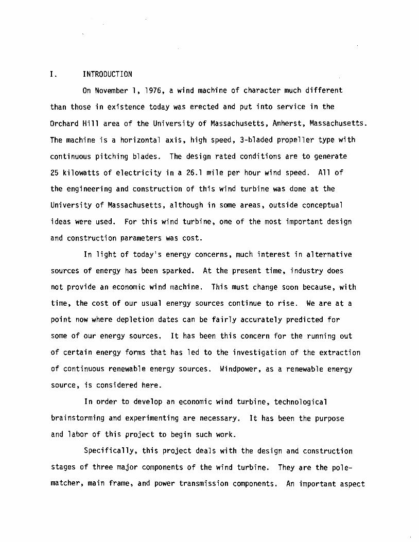
Wind Furnace Conceptual Layout
Approximate Main Frame Loading
Rated Thrus t Loading
Polematcher
Pol ematcher Rated Stresses
Polematcher E rec t i on Stresses
S l i p r i ng Deta i 1
S l i p r i ng Assembly
Main Frame Assembly
Main Frame Sect ion Stresses
Main Bearing Rib Stresses
Main Frame Base Stresses
W l nd Furnace-1 , L e f t P r o f i 1 e
Wind Furnace-1 , Right P r o f i l e
Truck Rear Axle Assembly
L u b r i c a t i o n Case Assembly
P in ion Sprocket Shaft
Page 7
I. INTRODUCTION
On November 1, 1976, a wind machine o f charac ter much d i f f e r e n t
than those i n ex is tence today was erec ted and p u t i n t o serv ice i n t he
Orchard H i l l area o f the U n i v e r s i t y o f Massachusetts, Amherst, Massachusetts.
The machine i s a ho r i zon ta l ax is , h igh speed, 3-bladed p r o p e l l e r type w i t h
cont inuous p i t c h i n g blades. The design r a t e d cond i t i ons are t o generate
25 k i l o w a t t s o f e l e c t r i c i t y i n a 26.1 m i l e per hour wind speed. A l l o f
t he engineer ing and cons t ruc t i on o f t h i s wind t u r b i n e was done a t the
U n i v e r s i t y of Massachusetts, a l though i n some areas, ou ts ide conceptual
ideas were used. For t h i s wind tu rb ine , one o f the most impor tan t design
and cons t ruc t i on parameters was cos t .
I n l i g h t o f today 's energy concerns, much i n t e r e s t i n a l t e r n a t i v e
sources of energy has been sparked. A t t he present t ime, i n d u s t r y does
no t p rov ide an economic wind machine. Th is must change soon because, w i t h
time, the cos t o f our usual energy sources cont inue t o r i s e . We a re a t a
p o i n t now where d e p l e t i o n dates can be f a i r l y accu ra te l y p red i c ted f o r
some o f our energy sources. It has been t h i s concern f o r t he running o u t
o f c e r t a i n energy forms t h a t has l e d t o the i n v e s t i g a t i o n o f the e x t r a c t i o n
of cont inuous renewable energy sources. Windpower, as a renewable energy
source, i s considered here.
I n o rder t o develop an economic wind tu rb ine , techno log ica l
bra instorming and experimenting a re necessary. It has been the purpose
and l a b o r o f t h i s p r o j e c t t o begin such work.
S p e c i f i c a l l y , t h i s p r o j e c t deals w i t h the design and cons t ruc t i on
stages of t h ree major components o f t he wind tu rb ine . They a r e the pole-
matcher, main frame, and power t ransmiss ion components. An impor tan t aspect
Page 8
of t h i s p r o j e c t r e p o r t i s t h e i n c o r p o r a t i o n and i n some cases, i d e n t i f y i n g
o f t r a d e o f f s and methods used t o c o n s t r u c t an economic, energy e f f i c i e n t
wind tu rb ine . A1 so inc luded a re comments on how t h e f i n a l methods and
designs cou ld be improved, s ince exper ience being a good teacher, c e r t a i n
designs were r e a l i z e d too l a t e t o be incorpora ted i n t o t he e x i s t i n g wind
tu rb ine .
Page 9
11. BASIC COMPONENTS AND SPEC1 FICATIONS
The design and c o n s t r u c t i o n c r i t e r i a o f t he UMass wind t u r b i n e
has two major cons idera t ions i n mind. One i s t h a t t h e machine can t u r n
an e l e c t r i c generator w i t h i n i t s e l f sending energy t o t h e ground through
t ransmiss ion wires; the o t h e r i s t o supply s h a f t work a t t h e ground l e v e l .
The former cons ide ra t i on has been l abe led Wind Furnace-I, (WF-I), and the
1 a t t e r , Wind Furnace-4 (WF-4).
A. Wind Furnace I (WF-1)
WF-1 i s c u r r e n t l y t h a t WECS which operates on t h e UMass Campus.
The main components, t o be considered i n t h i s r e p o r t , which make
up t h a t system a re t h e polematcher, main frame, and the t r u c k r e a r
a x l e assembly.
The polematcher i s a s t r u c t u r a l member which supports a l l o f
the wind t u r b i n e ' s loads and t rans fe rs them i n t o t h e tower. The
weight and r e a c t i o n t o t h e energy being developed by the r o t o r pass
through an a t tached tapered r o l l e r bear ing about which the machine
i s f r e e t o yaw. There i s a second p l a s t i c r a d i a l bear ing approx i -
mate ly 12" below which absorbs the second r e a c t i o n load . Between
these two bear ings i s a s e t o f s l i p r i n g s which a r e used t o t r a n s f e r
t he energy f rom t h e generator across t h e yaw a x i s and i n t o t he
ground transmi ss ion 1 i nes.
The main frame i s t h e s t r u c t u r a l beam about which the wind
machine i s b u i l t . I t s f u n c t i o n i s t o t r a n s f e r wind and weight
loads o f a l l i t s a t tached components t o t he polematcher. The
frame supports a 25 -k i l owa t t generator ( r a t e d a t 1800 RPM) on one
end and a wind r o t o r ( r a t e d a t 167 RPM) on the o the r end. The
placement of t he generator and wind r o t o r a re such t h a t t h e main
Page 10
frame balances a t the polematcher. Because o f t he d i f f e r e n c e
between the wind r o t o r and the generator r a t e d RPM, a speed d r i v e
w i t h a step-up r a t i o o f 1800/167 o r 10.82:l i s requi red.
The t r u c k r e a r a x l e assembly has a mu1 t i -purpose. I t helps
t o s t i f f e n the main frame i n t h a t i t i s b u i l t t o support heavy
loads. It has a s p e c i a l l y t r e a t e d ax le s h a f t and gears t o t rans -
m i t h igh torque requirements, a drum blade t o slow o r s top the
wind tu rb ine , and a r o t a t i n g hub t o which t h e wind r o t o r i s
attached. The hypoid gears, which a re encased i n the d i f f e r e n t i a l
housing, comprise the f i r s t o f a two-stage step-up d r i v e . They
a r e a 90' r i g h t angle d r i v e and have an o v e r a l l r a t i o of 4.86 t o
one. For t he WF-1, those gears a re angled t o the s ide so t h a t a
cha in and sprocket second stage speed d r i v e cou ld be added. I f
s h a f t power i s des i red a t ground l e v e l , then these gears p l u s the
whole d i f f e r e n t i a l a x l e assembly would be r o t a t e d 90' u n t i l t he
d i f f e r e n t i a l p i n i o n s h a f t p o i n t s s t r a i g h t down the tower. Then
w i t h a sho r t un i ve rsa l shaf t arrangement connect ing the a x l e d r i v e
through the polematcher t o the v e r t i c a l sha f t , WF-4 would be created.
One l a s t component t h a t should be mentioned here i s t he second
stage speed d r i v e . Considering t h a t t h e hypoid gear d r i v e has a
4.86 t o one r a t i o , then i n o rder t o achieve the o v e r a l l des i red
d r i v e r a t i o o f 10.82 t o one, t h e second stage speed d r i v e must have
a r a t i o o f 2.22 t o one. The second stage t ransmiss ion i s b u i l t o f
3" wide s i l e n t cha in on 42" centers. The chain i s l u b r i c a t e d i n
an o i l bath cons i s t i ng o f "Type A" o r "Dexeron" automatic t rans -
miss ion f l u i d .
Page 11
6. Wind Furnace 4 (WF-4)
WF-4 i s a wind system which does n o t u t i l i z e a wind generator
a l o f t , b u t i ns tead d r i v e s a mechanical churn. Once the generator
i s removed though, b a l l a s t should be added i n i t s p lace i n o rde r
t o ma in ta in t he wind machine balance. Ins tead of e l e c t r i c , s h a f t
power i s brought from the wind t u r b i n e through bulkhead bear ings
l oca ted w i t h i n t h e tower and then t o t he ground where i t would be
used i n whatever form i s desi red. A yaw d r i v e r may now become
necessary so t h a t t he r e a c t i o n from the v e r t i c a l sha f t torque does
no t yaw t h e machine from the wind d i r e c t i o n . S l i p r i n g s f o r t h i s
model may n o t be necessary a t a l l .
C. Summary
The conceptual arrangements of WF-1 and WF-4 had long been
l a i d o u t be fore t h e ac tua l i d e n t i f y i n g o f s p e c i f i c designs and
ma te r i a l s . The pr imary wind t u r b i n e designs were begun a f t e r t h e
basic elements o f t h e machine were se lected. The most impor tan t
element o f t he wind t u r b i n e about which a l l designs were centered
was t h e t r u c k r e a r a x l e assembly. As discussed l a t e r i n t h i s
r e p o r t , much cons ide ra t i on was g i ven t o choosing t h i s r e a r ax le ,
the most impor tan t being c o s t versus whether i t cou ld be mod i f i ed
f o r i t s new r o l e . The nex t element was the generator and f i n a l l y
sprockets and cha in as t h e f i n a l l i n k i n the d r i v e t ransmiss ion.
Wi th these elements i n mind, t h e pr imary designs were begun.
Page 12
111. PRIMARY DESIGNS
Before a r e a l i s t i c design could begin the quest ion of whether t o
b u i l d s t r u c t u r a l components ou t o f laminated f i b e r g l a s s o r s t e e l had t o
be evaluated. Due main ly t o the f a c t t h a t t ime was h u r r i e d and t h i s
designer knew l i t t l e o f working the f i b e r g l a s s laminates, the s tee l
design was chosen. Some i n t e r e s t i n g po in ts i n design o f f i b e r g l a s s lami -
nates were r a i s e d and presented here.
A. F iberglass Laminated Design
Probably the g rea tes t advantage t o b u i l d i n g a f i b e r g l a s s
design i s t h a t expensive machines and machinery are no t required.
The f i b e r g l a s s components could be molded i n pieces and then bonded
together w i t h f i b e r g l a s s and res ins o r one complete sec t i on could
be done a t one t ime. The man-hours requ i red f o r these jobs de-
crease as experience and knowledge increase. This was demonstrated
dur ing the UMass windpower p r o j e c t wh i l e cons t ruc t i ng the wind
t u r b i n e ' s blades. The bas ic design e n t a i l s molding a support ing
p la t fo rm w i t h r i bbed sect ions eminat ing from the tower o r pole-
matcher sec t ion . The t r u c k a x l e would n o t be permanently embedded
i n t o the f i be rg lass , but i t could be used along w i t h a re leas ing
agent t o have i t s form permanently molded i n t o a f i b e r g l a s s bed.
That way the t r u c k ax le could be e a s i l y taken ou t f o r r e p a i r .
Mounted t o t h a t p la t fo rm would be the var ious o ther accessories
such as a second speed dr ive , generator, and b a t t e r i e s . A channel
above the polematcher would s t i l l be provided i n the event t h a t
shaf t power a t the ground l e v e l i s desi red. An i n i t i a l disadvantage
i s the cos t of b u i l d i n g the molds, bu t t h i s cos t would be re turned
Page 13
as more machines were tu rned out . The advantages would be a
s t r u c t u r e o f low weight, h igh st rength, and no machining, c u t t i n g ,
o r welding costs.
B. Steel Design
The s t e e l design was thought o u t and cons t ruc ted from the p o i n t
o f view t h a t s t e e l would be bought i n the forms o f tubing, f l a t
p l a t e and angle i r o n . The procedure used from the i n i t i a l idea
t o the f i n i s h e d product i s as fo l l ows . A conceptual idea f o r the
e n t i r e machine was formed a f t e r reading m a t e r i a l on pas t windmil 1
designs and a f t e r engaging i n d iscussions w i t h o t h e r engineers on
the p r o j e c t . A working design was sketched o u t and discussed
again. A f t e r more refinement, t he design was presented a t a r e g u l a r
windpower group meeting where o t h e r c r i t i c i s m s were voiced. During
t h i s t ime, two + sca le cardboard models were bu i 1 t, the second
being a r e v i s i o n o f t he f i r s t . The models c l e a r l y showed how a l l
systems in te rac ted , t h a t i s spec i f i c placement of t he main frame
polematcher generator and t r u c k ax le .
With the acceptence o f t he f i n a l layout , i n d i v i d u a l assemblies
and subassemblies were i d e n t i f i e d . S p e c i f i c designs f o r each were
c a r r i e d o u t and evaluated i n t he same manner as the o v e r a l l design
w i t h the except ion t h a t t h e machine shop engineer, Professor Armand
Costa guided the designs f o r e f f i c i e n t machining. I n many ways
the advice o f t h i s man l e d t o good engineer ing p r a c t i c e i n the
f i n a l design. F igure 1 shows the accepted concept o f the wind
t u r b i n e w i t h the r e l a t i v e p o s i t i o n s of the bas ic elements. I n t he
Figure, the d i f f e r e n t i a l p i n i o n shaf t i s angled toward the ground
f o r t he WF-4 conf igura t ion . Component "A" would be b a l l a s t weight.
Page 14
I' i I-
t!!
I'
: I-J
Page 15
For the WF-1 conf igurat ion , the d i f f e r e n t i a l p in ion shaf t i s
r o t a t e d up 90°, Component "A" i s the generator and a sprocket
and chain d r i v e i s added. This model i s shown i n the wind t u r b i n e ' s
f i n a l assembly drawing l a t e r i n t h i s r e p o r t .
Page 16
I V . STRUCTURAL LOADS
I n order t o determine accura te ly t h e st resses t o which the machine
would be subjected, a good eva luat ion o f weight and wind loads had t o be
done. I n the ana lys is , on l y s t a t i c and no dynamic fo rces were considered.
Only a f t e r cons t ruc t i on began were the dynamic loads assessed. I n most
instances the s t a t i c eva lua t ion was s u f f i c i e n t . Only one dynamic l o a d was
o f any r e a l concern. That was a gyroscopic couple induced by the s imul-
taneous occurance o f r o t o r and yaw s p i n r a t e . This was f i n a l l y c o n t r o l l e d
by a yaw damper t h a t l i m i t e d the maximum yaw r a t e t h a t t he wind cou ld
induce on the machine.
A. Weight Loads
When the ana lys i s was f i r s t begun, i n i t i a l est imates f o r each
component was made. The est imated weight o f a l l supported compo-
nents l ess the n a c e l l e ' s main frame, l i g h t n i n g rod, and yaw damper,
was 1650 pounds, the actual weight was 1590 pounds. Once a l l t he
ex t ras were added the t o t a l combined weight was 2535 pounds.
Figure 2 shows the cu r ren t weight d i s t r i b u t i o n i d e n t i f y i n g most
components as p o i n t loads. I n comparison t o t h i s loadings moment
diagram, the c u r r e n t est imate compares w e l l w i t h the f i r s t attempt
from which the o r i g i n a l design stemmed. An unusual load ing condi-
t i o n which i s o f concern occurs when the machine i s mounted t o the
tower before the tower i s erected. The machine i s now l y i n g on
i t s s ide and so the load ing c o n d i t i o n now changes t o 90" o f the
normal p o s i t i o n . The load ing fo rce w i l l increase as the tower i s
l i f t e d i n t o i t s opera t ing p o s i t i o n . From the weight and balance
t a b l e i n Appendix I, the v e r t i c a l c e n t r o i d i s 9.76 inches above
the top of the polematcher o r 13.3 inches above the main bearing.
Page 17
APPRO- MAllJFRAME m I N G
FIGURE 2
Page 18
Knowing the weight o f the machine and using a simple beam ca lcu la -
t i o n , t he r a d i a l f o rce on the main bear ing and polematcher i s
5070'. I f the machine i s i n i t i a l l y accelerated from the ground
a t 1.5 t imes t h e acce le ra t i on o f g r a v i t y , then t h i s fo rce becomes
# 7605 , which becomes a design c r i t e r i o n .
B. Rated Loads
The r a t e d machine loads are determined main ly by the power
t h a t t he machine i s designed t o e x t r a c t from the wind, t h e wind-
speed t h a t corresponds t o t h i s power l e v e l , and the designed r a t i o
QR - of blade t i p speed t o windspeed o r - 7.45, a design power r a t i n g 0
o f 25 k i l o w a t t s and a design windspeed o f 26.1 mph. Using the
QR blade rad ius o f 16.25; design r, and the r a t e d windspeed o f 0
26.1 rnph, the r a t e d s h a f t speed becomes 167 rpm. I f a 67% d r i v e
e f f i c i e n c y i s assummed, then 37 Kw i s requ i red a t t he windshaf t ,
and f o r 167 rpm, the corresponding torque would be 1567 f t - l b s .
Here an assumption was made t h a t a l though an overspeed would
increase the s h a f t torque v i b r a t i o n a l t r a n s i e n t s o r resonant
frequencies would not . A r e p o r t publ ished i n the UMass wind
research progress r e p o r t f o r the pe r iod May-December 1976 supports
t h i s assumption.
Wind r o t o r t h r u s t i s ca l cu la ted from t h e i d e a l t h e o r e t i c a l
t h r u s t - 419 112 pAVoZ. For t h i s machine a t 26.1 mph, the t h r u s t
i s 642 pounds adding 10% f o r n a c e l l e drag i s 707 pounds. Rea l i z ing
t h a t a t ra ted windspeed the p r o b a b i l i t y o f a f a s t - a c t i n g gust i s high,
t he design t h r u s t f o rce was chosen as f o u r t imes t h e i d e a l t h r u s t
f o r 26.1 mph. Because t h r u s t i s p ropor t i ona l t o Yo: than a f a c t o r %
o f 4 corresponds t o ( 4 ) = o r two t imes the r a t e d windspeed. The
Page 19
design t h rus t becomes 2828 pounds, Figure 3.
One other ra ted load was the moment o f angular momentum
induced a t the wind r o t o r due t o simultaneous yaw and r o t o r
spin ra te . I n a 1IMass wind energy repor t , "Design o f Hub and
P i t ch ing System f o r WF-I", June 1977, i t was shown t h a t a moment
of 400 f t - ' lbs would e x i s t i f the yaw r a t e were allowed a maximum
of one rpm. A yaw damper was added t o cont ro l t h i s . Hurricane
force winds on a shutdown machine using nace l le drag on ly were
two magnitudes o f order smaller than the t h r u s t values f o r doubled
windspeed, therefore, hurr icane winds pose no th rea t so long as
the machine i s shut down.
Page 21
V. MAIN COMPONENTS
The main components o f t he WF-1, which t h i s r e p o r t deals w i t h a re
polematcher, main frame, and t ransmiss ion d r i ves . I n the f o l l o w i n g sec t i on
the design cons t ruc t i on and comen t on each element i s discussed. From t h e
prev ious sect ion, loadings were i d e n t i f i e d w i t h probable est imates o f
t r a n s i e n t o r unusual forces. Factors o f s a f e t y w i l l be app l i ed
i n t h i s sec t i on and r e f e r t o t he p o i n t o f permanent y i e l d . Each component
described i s t h a t s p e c i f i c one used i n t h e e x i s t i n g WF-1.
A. Pol ematcher
1. Design
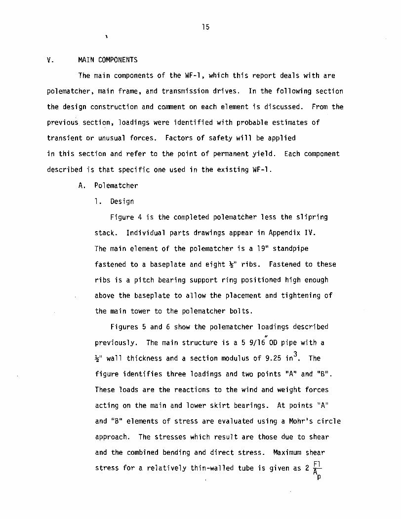
F igure 4 i s t he completed polematcher l e s s t h e s l i p r i n g
stack. I n d i v i d u a l p a r t s drawings appear i n Appendix I V .
The main element o f the poleniatcher i s a 19" standpipe
fastened t o a baseplate and e i g h t &" r i b s . Fastened t o these
r i b s i s a p i t c h bear ing support r i n g pos i t i oned h igh enough
above the baseplate t o a l l o w the placement and t i g h t e n i n g o f
the main tower t o the polematcher b o l t s .
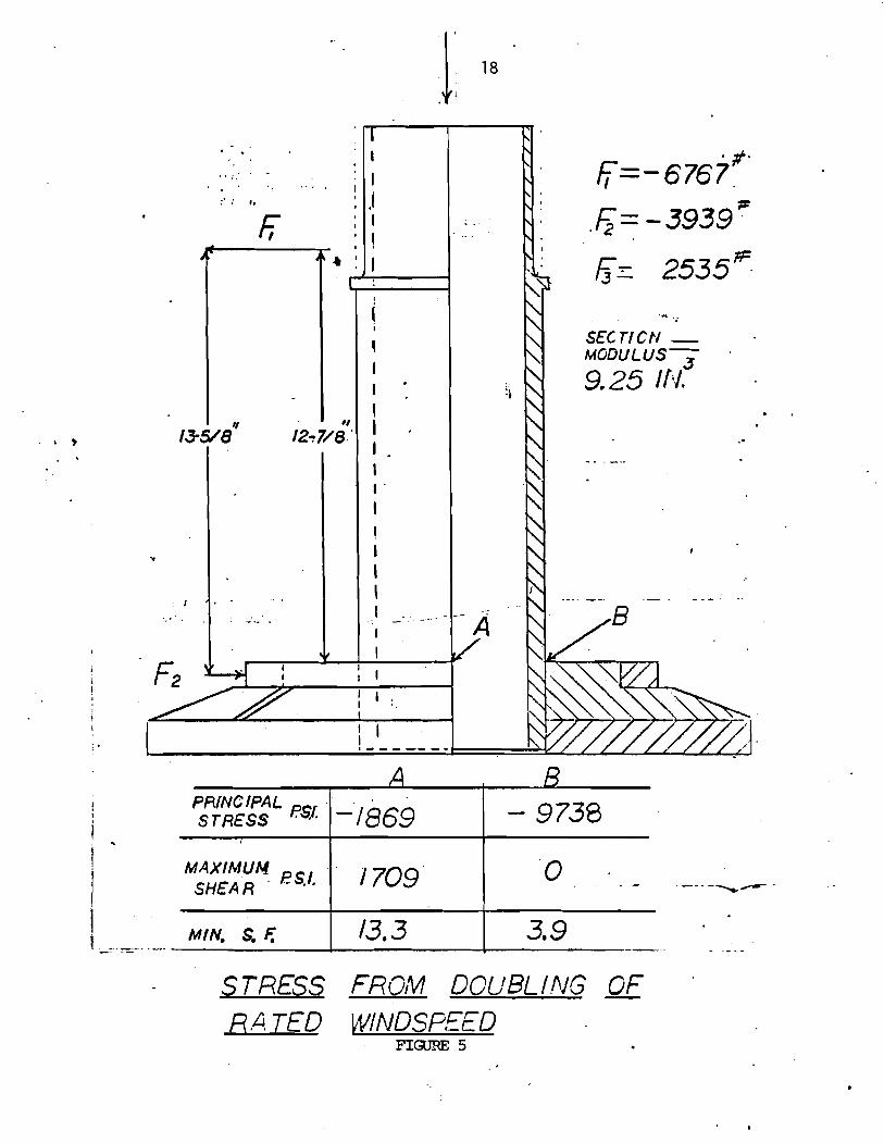
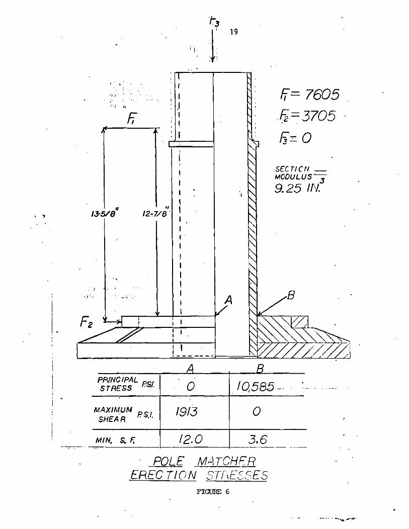
F igures 5 and 6 show the polematcher load ings described II
prev ious ly . The main s t r u c t u r e i s a 5 9/16 OD p ipe w i t h a
3 k" w a l l th ickness and a sec t i on modulus o f 9.25 i n . The
f i g u r e i d e n t i f i e s th ree loadings and two p o i n t s "A" and "B".
These loads a r e the reac t i ons t o t h e wind and weight fo rces
a c t i n g on the main and lower s k i r t bearings. A t p o i n t s "A"
and "B" elements o f s t ress a re evaluated us ing a Mohr's c i r c l e
approach. The st resses which r e s u l t a re those due t o shear
and the combined bending and d i r e c t s t ress . Maximum shear
F 1 s t r e s s f o r a r e l a t i v e l y th in-wal l e d tube i s g iven as 2 P
Page 22
TZLEFiANCES UPiLESS CTtiERCVI5E S =5C;F/EO + .Of
SCALE / /2 FIGURE 4
Page 23
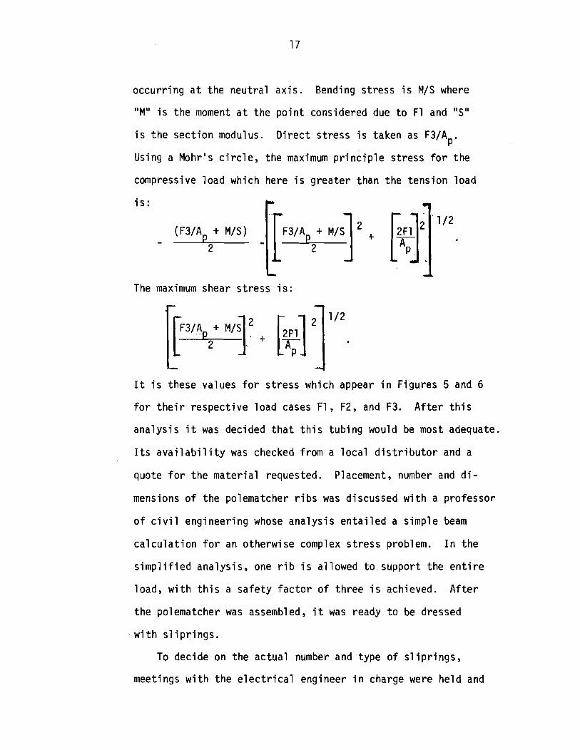
occu r r i ng a t the neu t ra l ax i s . Bending s t ress i s M/S where
"Mu i s t h e moment a t the p o i n t considered due t o F1 and "S"
i s t h e sec t i on modulus. D i r e c t s t ress i s taken as F3/Ap.
Using a Mohr's c i r c l e , the maximum p r i n c i p l e s t ress f o r t he
compressive l oad which here i s g rea te r than the tens ion l oad
i s :
- (F3/A + M/S) M,sl + 12. 2
The maximum shear s t ress i s :
I t i s these values f o r s t ress which appear i n F igures 5 and 6
f o r t h e i r respec t i ve l oad cases F l y F2, and F3. A f t e r t h i s
ana lys i s i t was decided t h a t t h i s tub ing would be most adequate.
I t s a v a i l a b i l i t y was checked from a l o c a l d i s t r i b u t o r and a
quote f o r t h e m a t e r i a l requested. Placement, number and d i -
mensions o f the polematcher r i b s was discussed w i t h a p ro fessor
o f c i v i l engineer ing whose ana lys i s e n t a i l e d a s imple beam
c a l c u l a t i o n f o r an otherwise co~nplex s t r e s s problem. I n the
s i m p l i f i e d ana lys is , one r i b i s a l lowed t o support t he e n t i r e
load, w i t h t h i s a s a f e t y f a c t o r o f t h ree i s achieved. A f t e r
t he polematcher was assembled, i t was ready t o be dressed
w i t h s l i p r i n g s .
To decide on the ac tua l number and type o f s l i p r i n g s ,
meetings w i t h t h e e l e c t r i c a l engineer i n charge were he ld and
Page 24
PRINCIPAL pS, ,
STRESS 1-1869
MAXIMUM SHEAR - FSIc.
STRESS FRGM DOUBLING OF R A TED WINDSP,EED
FIGURE 5
Page 25
MIN. S. E
POLE MATCHFR EREC TION STTIE-ZFES
Page 26
decis ions made. It was decided t h a t s i x 9/16" wide s l i p r i n g s
would be r a t e d f o r h igh power capaci ty , s i x 5/16" wide f o r
medium duty, and th ree 3/16" r i n g s f o r ins t rumenta t ion . Using
4" spacing between t h e r i n g s , t h e completed s tack i s 9 5/16''
h igh and i s pos i t i oned 1%" above t h e lower polematcher bear ing
and one i n c h below t h e main bearing. The s l i p r i n g s a re made
of SAE 660 bear ing bronze w i t h a 6%" I D and a 7%" OD. The
6.5" I D gave s u f f i c i e n t clearance between i t and t h e polematcher
standpipe f o r t h e embedment o f t ransmiss ion w i res i n f i b e r g l a s s
and r e s i n f i l l e r s . F igures 7 and 8 show d e t a i l o f t h e s l i p -
r i n g stack. Each s l i p r i n g has two w i res at tached t o i t f o r
redundancy.
2. Const ruc t ion
As mentioned e a r l i e r , be fore t h e c o n s t r u c t i o n o f a p a r t
began, guidance toward e f f i c i e n t machining was sought from
t h e machine shop foreman and incorpora ted i n t o the f i n a l design.
Wi th a l i t t l e experience on t h e p a r t o f t h e designer, t h e
member o f these d iscussions were reduced and t ime saved. One
impor tan t cons idera t ion was t h a t , i f possib le, t h e f i n a l
machining on a l l p a r t s would take p lace o n l y a f t e r a l l t h e
weld ing and gas c u t t i n g was performed. A t t imes, t h i s posed
problelns, bu t t h e end r e s u l t was a b e t t e r qua1 i t y on i n d i v i d u a l
p a r t to lerances. If welding o r gas c u t t i n g had taken p lace
a f t e r t h e c r i t i c a l machining, t h e thermal s t ress as a r e s u l t o f
t h e h igh temperature would have caused warping i n t h e f i n i s h e d
product. This problem surfaced i n t h e cons t ruc t i on o f t h e
Page 28
UNIVEfiLITY OF MASSACHUSE'TTS
SLIP RING ASSEMBLY O W I N G NO 05 -02 -02 -31
1 s m y~s/lr DRrull sr F * N T ~ N
Page 29
polematcher when i n one afternoon, t h e e n t i r e assembly was
welded together . The s t r u c t u r e became no t i ceab ly warped even
beyond t h e he lp o f machining. It was found though, t h a t by
making use o f a 60-ton press, t he weldment could be res to red
t o t h e designed geometry. Two mach in is ts centers were placed
on t h e top and bottom o f t h e polematcher. I t was through t h i s
a x i s t h a t a l l f i n a l machining was accomplished. Now t h e pole-
matcher i s ready f o r t he attachment o f s l i p r i n g s .
The standpipe OD i s 5 9/16", t he s l i p r i n g I D i s 6+", i n
order t o f i t t h e s l i p r i n g s t h e sur face o f t h e polematcher must
be increased t o a th ickness o f 15/32" us ing an i n s u l a t i n g
ma te r ia l , f i b e r g l a s s mat t ing , and epoxy r e s i n . The i n s u l a t o r
was b u i l t t o j u s t over +I1 t h i c k and then machined down so t h a t
t he s l i p r i n g s would have a snug f i t and no t s l i d e e a s i l y . To
t h e s l i p r i ngs were soldered copper w i res 180D apar t . The heavy
s l i p r i n g s ge t #8 w i re , t h e medium #14, and the ins t rumenta t ion
r i n g s sh ie lded coax ia l cable. A f t e r p repar ing t h e s l i p r i n g
s tack as i n F igu re 8, t he s l l p r i n g s were tapped and cemented i n t o p lace
w i t h the e l e c t r i c power l i n e s being threaded underneath the pre-
v i o u s l y i n s t a l l e d s l i p r i n g s i n s i d e t h e 5/16" square channels.
Once t h a t cement had set , t he polematcher was s low ly turned on
a l a t h e w h i l e a m ix tu re o f epoxy r e s i n and th i cken ing agent was
poured between t h e s l i p r i n g s . A t t h e t o p and bottom o f t he
stack,cardboard forms were used t o r e t a i n t h e r e s i n . A s u f f i -
c i e n t amount of r e s i n was added u n t i l t h e s l i p r i n g spaces were
f i l l e d f l u s h t o t h e s l i p r i n g OD. A f t e r t h e r e s i n cured, t h e
f i n a l machining was done. A t t he same t ime, t h e main bear ing
Page 30
seat and lower p i t c h bear ing suppor t were machined t o s p e c i f i -
ca t ions . The p l a s t i c p i t chbea r ing tu rned t o i t s f i n a l dimension
and f i n a l l y a l i g h t t u r n i n g of t he s l i p r i n g s was done f o r p o l i s h i n g .
I n o rder t o prevent weather f rom blowing underneath the
lower p i t c h bear ing and i n t o t h e s l i p r i n g s tack, each r i bbed
compartment o f t he polematcher was f i l l e d w i t h foam and then
sealed w i t h a wood g lue. A l i g h t l y greased main bear ing added
and t h e polematcher was complete. The mach in is ts cen ters may
o r may n o t be removed a t t h i s p o i n t .
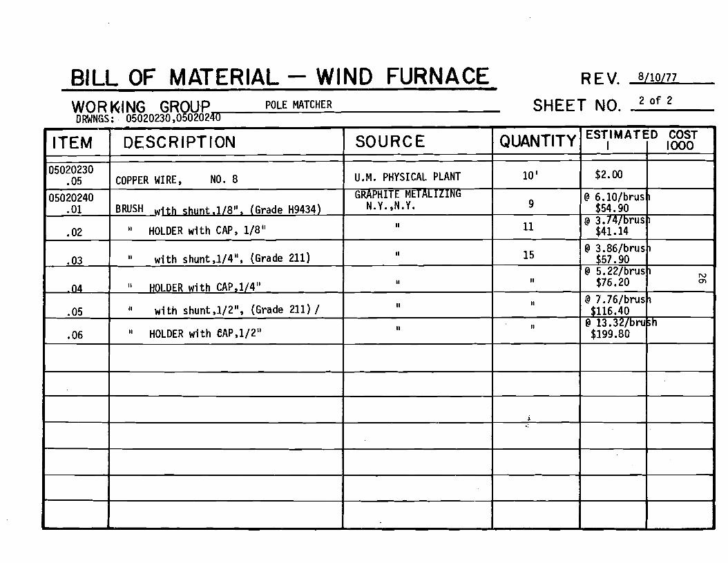
3. Cost
The f o l l o w i n g i s t h e b i l l o f polematcher m a t e r i a l s and costs.
The p r i c e s r e f l e c t l a t e 1975 quotes.
Page 31
BILL OF MATERIAL - WIND FURNACE REV. 8110177
WORKING GROUP POLE MATCHER SHEET NO. 1 o f 2 DRWNGS
ITEM
05020201 ,01 -
.02
05020203 01
.02
*03
05020205 .01
.02
.03
.04 05020220
. O 1 05020230 - 01
02
nq
.04
SOURCE
A.B. MURRAY SHARON ,MA.
DUANES ' STEELYARD : OUINCY 9
,0.:r511thick) SHOP
II
EASTERN BEARING FITCHBURG,MA, MILL D C . BRAIi:REE ,k.
I1
II
II
SHOP
ACCURATE FASTENER SO. BOSTON, MA
(I
II
T.F.E. PROVIDENCE,R. I.
: 05020201,05020203,05020205,05020220
DESCRIPTION
POLE MATCHER STEM ,5"Nom. Sched. 120 5 9/16'' O.D. w i t h 112" wal l
POLE MATCHER BASE PLATE, ( 1 8 " ~ i a .xll'Thick
PITCH BEARING RING, (10~~1 .D. ,12. ~ " O . D .
POLE MATCHER RIBS 5.25" BORE TAPER ROLLER BEARING EQUIV.
.:o a Tyson Cone X48290 &cup X48220
SLIP RING MATERIAL, (SAE660 brg. bronze)
RINGS (7.5~6.5~9116)
II II (7.5 x 6.5 x 5/16)
II II (7.5 x 6.5 x 3/16)
MAIN BEARING SUPPORT, (5.5" Dia. om.)
HEX HMO BRAS CAP SCREWS ,(5/16-18 ~ 1 . 2 5 )
FINISHED HEX BRASS NUTS
FLAT BRASS WASHERS
PLASTIC PITCH BEARING (PV-80) 13.5" O.D. ,12" I.D., x 3/411 t h i c k
QUANTITY
19"
1
1
8
1
ESTIMATED I COST
$32.00
$7.50
$22.00
$8.00
$63.58 _I
I 1000
lw Ln
I
A
13"
6
II
3
l 1
3 6
72
36
1
$5.00
@ 0.263 ea. $9.47 @ 0.078 ea. $5.62
8 0.058 ea. $2.09
$25.00
Page 32
BILL OF MATERIAL - WIND FURNACE --
WORKING GROUP POLE MATCHER SHEET NO. 2 o f 2
' QUANTITY
10 '
9
11
15
II
II
It
i
ESTIMATED I
$2.00
@ 6.101brus $54.90
@ 3.74/brus $41.14
@ 3.86/brus1 $57.90
@ 5.22/brus $76.20
@ 7.76/brus $116.40
@ 13.32/brush $199.80
SOURCE
U.M. PHYSICAL PLANT
p-
N.Y. ,N.Y.
#I
I~
la
II
II
DRWNGS: 05020230,05020240
1000 COST
1
I
I N 01
I
3
ITEM
05020230 .05
05020240 .01
.02
.03
04
.05
.06
- 1
DESCRIPTION
COPPER WIRE, NO. 8
BRUSH w i th shunt ,l/8", (Grade H9434)
I' HOLDER wi th CAP, 1/8"
I' w i t h shunt ,l/4", (Grade 211)
II HOLDER w i th CAP, 1/4"
" wi thshunt , l /2" , (Grade 211) /
HOLDER wi th eAP,1/2"
Page 33
B. Main Frame
1. Design
The i n i t i a l concept o f t h e main frame i s based on the
general arrangement o f t h e t r u c k r e a r a x l e assembly and t h e
generator. The basic parameters f o r the main frame l a y o u t
i s t h a t i t would support the t r u c k r e a r ax le assembly a t t he
same p o s i t i o n s a t r u c k i t s e l f would mount. The assembly
would be supported h igh enough above the top o f t he pole-
matcher so t h a t when converted t o t h e WF-4, s u f f i c i e n t c l e a r -
ance would be al lowed t o make t h e ground shaf tconnect ion.
The p o s i t i o n o f t h e generator should be f a r enough away from
the hub and blades so t h a t t he machine would balance a t the
polematcher. For the f i r s t guess i t was thought t h a t ZOO#
would have t o be added a t t h e l o c a t i o n o f t h e generator t o
balance the frame on the polematcher. Th is ZOO# was l e f t as
leeway aga ins t t h e f a c t t h a t more accessories would be added
there t o he lp balance the frame. A f t e r t h e f i n a l weight and
moment sheet was produced (Appendix), i t was found t h a t a n e t
342 inch-pound moment ex i s ted a t t h e polematcher and t h a t on l y
n ine pounds would have been requ i red a t the generator s t a t i o n
t o o f f s e t t h i s . The balancing o f t h i s moment was due main ly
t o the a d d i t i o n o f t h e yaw damper, l i g h t n i n g rod, o i l and 1 ube
case, and the main frame center o f g r a v i t y . This moment was /
considered so small t h a t b a l l a s t was n o t added. As a r e s u l t
o f t h e s i l e n t chain d r i ve , a s ide moment o f 3563 inch-pounds
d i d e x i s t . Th is i s expected t o be reduced somewhat when b a t t e r i e s
and l o g i c c i r c u i t s are added t o t h e opposi te s ide o f t h e main frame.
Page 34
b
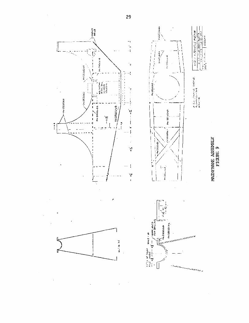
The type of cons t ruc t i on f o r t he main frame made very
few changes t o f i n a l l y ge t t o i t s present design, F igure 9.
The f i r s t type considered was t h a t us ing t r u s s nien~bers formed
o u t o f angle i r o n . The design would have been l i g h t , bu t i t
was feared t h a t n o t knowing exac t l y how the var ious accessories
would be mounted, a design us ing f l a t p l a t e was adopted. The
l a r g e sur face area o f t h e p l a t e s t e e l o f f e r e d many convenient
l oca t ions f o r adding t h e accessories. A lso , i f a p a r t o f t he
main frame needed t o be removed, i t could be done so w i thou t
jeopard iz ing the s t r u c t u r a l i n t e g r i t y . With a gas c u t t i n g
torch, t he frame sect ions would be easy t o c u t ou t as pa t te rns
from the main drawing. Some s t e e l companies have a machine
which w i l l c u t o u t f u l l sca le p a r t s from t h e p lan view o f t h e i r
respect ive drawings. Quotes were again gathered f o r t he s t e e l
and are r e f l e c t e d i n t h e cos t tab les .
Because t h e c o n t r o l l i n g dimensions from the polematcher and
t r u c k a x l e decrease w i d t h and height , a tapered appearance was
chosen. Holes were c u t i n t h e s ides o f t h e frame t o reduce
weight and a l l o w access t o any component i n s t a l l e d w i t h i n the
frame. Bulkheads were designed a t c e r t a i n l oca t ions t o i nsu re
s t i f f n e s s .
When the beam was designed, i t was assumed t h a t i t s s t reng th
was adequate. When the beam ana lys i s was done on ly f i v e c r i t i c a l
sect ions were evaluated. F igure 10 shows those sect ions evaluated
w i t h Sect ion "DD" being t h e most c r i t i c a l . Inc luded i n the
ana lys is i s the s t r u c t u r a l advantage o f t he t r u c k assembly.
Page 35
' I ,. I " , ;'
I a- j s.. .. , B \
\ '.-
Page 36
A t sec t i on "DD" where the g rea tes t bending moment occurs, a
s t ress c a l c u l a t i o n was a l s o done assuming t h e t r u c k d i f f e r e n t i a l
o u t o f p lace f o r the normal l oad ing condi t ion, p lus the machine
e r e c t i o n condi t ion, where t h e ~ n a i n frame wind a x i s i s para1 1 e l
t o the ground (frame on i t s s ide ) . F igure 10 shows the r e s u l t s
o f t h e ana lys i s f o r bo th 118 and 3/16" s t e e l p l a t e . The moments
used t o determine the sec t i on st resses a r e those taken from the
weight load ing i n F igure 2 f o r t he r a t e d t h r u s t loads.
Stress sec t ions of t he beam were n o t evaluated because of
t he extremely l a r g e area illonlent o f i n e r t i a along t h a t ax is .
The f i n a l ana lys i s concerns the f o r c e f l o w path i n t o the
polematcher. O f g rea tes t concern i s t h e area about t h e main
bear ing where the weight o f the machine i s c a r r i e d and the
g rea tes t r a d i a l force occurs. E s s e n t i a l l y t h e r i b s take t h e
e n t i r e load here. F igure 11 shows the worst case load and t h e
corresponding compressive s t r e s s l eav ing a s a f e t y f a c t o r o f
about 2. For t he lower p i t c h bearing, i f one assumes t h i s t o
be a bar p o i n t loaded as i n F igure 12, t he bending st resses
leave a s a f e t y f a c t o r o f about one. By l o o k i n g a t t he s t r u c t u r e
around the assumed bar, one r e a l i z e s t h a t i t does indeed con-
t r i b u t e t o the o v e r a l l s t r u c t u r a l i n t e g r i t y and, there fore , must
conclude t h a t t he s a f e t y f a c t o r i s reasonably g rea te r than one.
2. Const ruc t ion
Except f o r one area, the cons t ruc t i on of t h e main frame
progressed w e l l . The one cons t ruc t i on d i f f i c u l t y was the con-
c e n t r i c machining o f t h e main and s k i r t bear ing surfaces. Th is
was done by s e t t i n g the f i n i s h e d main frame on a ho r i zon ta l
Page 37
SECTION STRESS RESULTS . i '. .
SECTION
MOMENT DUE TO WEIGH T @-LEG)
3/16'' AREA INERTIA fiN *)
FRIN ClFAL STRESS (ps$ LESS ( F S ~ )
DIFFERENTIAL
- AA
904
428
34
( P S I ) SIDE w o / o i ~
I ' W-LTE/PSIJ 231
B 6
69e5
839
101
566
CC
15015
1467
1 566
-..--&
DO
1 / 7 8
29.581
2012
I 6 5 ' 2 9 7
1777
1968 1 1/35 1
18882
1 /47
2 3 7
Page 38
SIh4PLIFIED RIB
k- 3.5" -y
S T ~ S S ANALYSIS
6767* ,
BENDING - STRESS - 2 2 0 0 7 PSI
SHEAR STRESS - - 1 9 2 4 8 PSI
MA IN BE4FilNG COLLAR RIB
I
I1 P
2535- 8
MAIN
I L
\\\\\\\\\\\\\ FIGURE 12
Page 39
m i l l i n g machine. The m i l l i n g sp ind le was replaced by a crank
and t o o l b i t . Care was taken i n t h e machining so t h a t d e f l e c t i o n s
o f t h e crank could be he ld t o a minimum i n order t h a t t he
to1 erances could be held.
The frame was welded together i n t h e f o l l o w i n g manner.
A f t e r welding t h e r i b s t o t h e main bear ing c o l l a r , t h e c o l l a r
ID was turned t o .I" under t h e f i n i s h e d dimension. The frame
s ides and bulkheads were c u t o u t us ing bo th a c u t t i n g t o r c h
and t a b l e saw. The bulkheads were f i r s t a t tached t o one s i d e
o f t h e frame and then t h e o the r s ide was welded i n t o place.
The t r u c k support saddle, main bearing c o l l a r , and frame base
were added. F i n a l l y , t h e bear ing surfaces were bored concen-
t r i c a l l y and then the frame painted. The polematcher and
main frame were j o ined a t t h i s t ime.
The polematcher i s b o l t e d on to a l a r g e s tu rdy p a l l e t . A l l
o f t h e polematcher-to-tower b o l t s should be used because once
the frame i s lowered onto the polematcher, t he re i s no t enough
clearance t o i n s t a l l them. The main bear ing i s l i g h t l y greased,
i n s t a l l e d and then the frame i s lowered onto the polematcher.
The main bear ing has a very steep r o l l e r angle. It would take
an extremely l a r g e s i d e load t o a1 low t h e bear ing cup t o s l i d e
up t h e face o f the cone r o l l e r , there fore , t he weight o f t h e
machine and i t s c e n t r o i d being very c lose t o t h e polematcher i s
t he on l y ho ld down f o r c e requ i red . During erec t ion , i t i s q u i t e
poss ib le f o r t h e machine t o s l i p o f f t he polematcher. To c o r r e c t
f o r t h i s , two l o c k i n g caps a re screwed onto t h e polematcher,
1 / 3 2 " above t h e main bear ing c o l l a r , and then t igh tened aga ins t
Page 40
each o ther f o r l o c k i n g purposes.
I n s i d e the main frame s l i p r i n g housing, two brush b locks
are b o l t e d t o the main frame base p l a t e and 3/4" x 3/4" carbon
brushes wipe over t h e top o f t he polematcher r ing)wh ich i s
I tem 3 i n F igure 3. This i s f o r l i g h t n i n g p ro tec t i on , so t h a t
c u r r e n t does n o t f low through the i n f i n i t e s i m a l contac t area
o f t h e main tapered r o l l e r bearing. I f t h i s were t o occur, t he
bear ing could poss ib l y weld i t s e l f together .
3. Ma te r i a l s and Costs
The f o l l o w i n g i s t he b i l l o f main frame m a t e r i a l s and cos ts .
The p r i c e s r e f l e c t l a t e 1975 quotes.
Page 41
BILL OF MATERIAL - WIND FURNACE REV, 8/10/77
WORKING GROUP MAINFRAME COMPONENTS DWNGS : 0502Ol01,05020102,05020112,05020113,05020114,05020116,~
SHEET NO. Of
I
1 TEM I DESCRIPTION 1 SOURCE ESTIMATED COST NTITY [ I I 1000
05020101 .01
.02 05020102
. as
GENERATOR BEARING FOUNDATION PEDESTAL 13
05020112 01
02
I 1 11 II FLANGES
LOWER PITCH BEARING OUTER RACE ( 1 6 x 1 8 ~ 1 ~ )
*O3 05020113
.01
MACHINE SHOP
MmFRAME DECK, 3/16" P la te Steel
FRONT LOWER BRACES, (2"x43 "x3/16")
05020114 .O1
II II
11 II
REAR LOWER BRACES, 211 2211 3/16"
MAINFRAME SIDES, 3/16" Steel Plate
.02 05020116
.O1
. 05020118
. O l
.02 05020121
.O1
218' s t1
II I1
II II
MAIN AXLE SUPPORTS, (Top l2I1,Bot. 11 .9I1,Htl II II
$4 .OO
s t1
1/55'
II 8
II II
MAINFRAME BULKHEADS,(" 12", " 17.4", " 1:
MAIN AXLE SUPPORT,(t5.11',b 13.3",h 22.3")
FORWARD BULKHEADS, (t 12I1,b 16.6I1,h 11.8")
MAIN BEARING BRACE, (9" O.D. ,6.5"Mm, I .D
RIBS FOR MAIN BEARING SUPPORT -
[P IN ION BEARING BRACKET I
$1 .oo
$26.00
1 /43'
2/10'.
3/25'
- - - -
$22.00 W
$5.00 VI
7/4.5#
21122'
$12.50
.8") " II
11 II
II 11
1 II II
I1 8
II I1
$2.25
$61.00
2/22#
1 / 9 #
1/9#
1
613'
I 1/5#
$11.00
$5.50
$4.50
$39.10
$2.00
1 $ 3 - 0 0 I
Page 42
BILL OF MATERIAL - WIND FURNACE WOR GROUP MAINFRAME COMPONENTS SHEET NO. 2 o f 3
QUANTITY
1/11
113'
21 2#
115'
114'
l/lX
I1
114'
21 21
I1
i
l/l#
II
1/8#
1/21
SOURCE
MACHINE SHOP
II I1
II I1
II Il
I1 I1
I1 I1
11 II
I1 11
II II
I1 I1
I t I1
I1 II
I1 I1
I1 II
DRWNGS
ITEM 05020121
.01
050201 22 .01
.02
.03
.04
.05
.06
.07
05020124 .O1
.02
.03 L
-04 05020131
.O1 - ,02
' ESTIMATED I
$1.00
$1 .OO
$2.00
$2.50
$2.00
$1.00
$1 .oo
$2.00
$1.00
$1 .oo
$1.00
$1.00
$4.00
$1.00
: 0121 ~05020122,05020124,05020131 . DESCRiPTlON
P I N I O N BEARING SPACER
I1 BRACKET BASE
I1 I' FOUNDATION STRAPS
II I1 I1 CROSS BRACE
I1 " BRACKET SUPPORT
II II II I1
' FOUNDATION " I1
I1 II II PEDESTAL
II II 11 FLANGES
II II I1 SIDES
OUTBOARD GENERATOR BEARING BRACKET
INBOARD II II Il
BOLTS AND I1 I1
GENERATOR BEARING BRACKET BASE
COST 1000
w 01
-
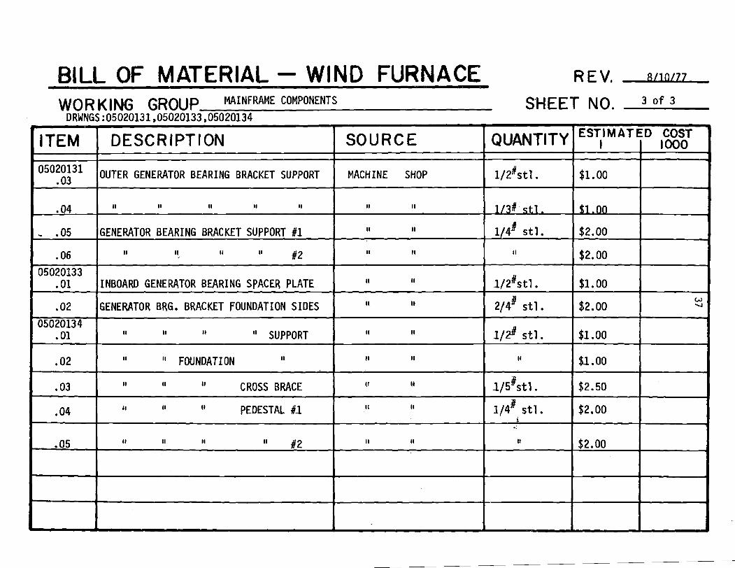
Page 43
BILL OF MATERIAL - WIND FURNACE wo R K ~ N G GROUP MAINFRAME COMPONENTS
DRWNGS :05020131,05020133,05020134
ITEM 1 DESCRIPTION 1 SOURCE
.O1
.02
05020134 . 01
, 0 2
.03
REV. s/lOLU
INBOARD GENERATOR BEARING SPACER PLATE
GENERATOR BRG. BRACKET FOUNDATION SIDES
I1 I1 I1 I' SUPPORT
.04
- SHEET NO. 3 o f 3
11 I1
I1 It
II II
I1 I' FOUNDATION II
I1 II II CROSS BRACE
ESTIMATED COST QUANTITY I 1000
II I1
11 II
II II II PEDESTAL #I - -
II II
Page 44
C. Power Transnli s s i on
The idea o f being ab le t o vary the form o f t h e energy t r a n s f e r r e d
from the wind t u r b i n e t o t h e ground was kept i n mind throughout the
design. The primary corr~ponent t h a t was considered t o make t h e
change o f generat ing e l e c t r i c i t y a l o f t o r sending s h a f t work t o
the ground was ' the t r u c k rea r ax le assembly. Two quest ions had t o
be answered though before work w i t h t h i s concept could begin. The
f i r s t quest ion o f cos t was analyzed and found t h a t t h e . p r i c i n g o f
a speed d r i v e o f equ iva lent capac i ty t o t h a t a l ready a v a i l a b l e i n
the a x l e assembly exceeded the cos t o f t he a x l e assembly. There-
fo re , t he immediate advantages o f the a x l e assembly above the speed
d r i v e i t housed were: t he 96 s h a f t d r i v e requ i red f o r t he WF-4,
the support ing s t r u c t u r e f o r t he 9# speed d r i v e assembly, t he r o t o r
spindle, r o t o r , h igh s t reng th shaf ts , r o t o r bearings, and brake
mechanism. The disadvantage o f t he ax le asseml by and second quest ion
t o be answered was: could the assembly be modi f ied t o s u i t t h e
needs o f t he wind tu rb ine . O f major concern was d r i l l i ng a 5/8"
hole the e n t i r e l e n g t h of t he t r u c k a x l e s h a f t f o r purposes o f a
blade p i t c h i n g 1 i n k and t o be ab le t o l ock the d i f f e r e n t i a l gears
so t h a t t he hypoid gear d r i v e could be used. I n order t o help
decide whether these mod i f i ca t i ons could be possib le, a used compare-
ab le t r u c k a x l e assembly was purchased from an automotive graveyard.
Using t h i s , i t was determined t h a t mod i f i ca t i ons were possib le.
A new t r u c k a x l e assembly was then purchased and used i n the
e x i s t i n g wind tu rb ine , WF-1. Although the d e t a i l e d design f o r
WF-4 was not done, t h e t o t a l through process was, and i s presented
here.
Page 45
1. Design
a. Wind Furnace-4 (WF-4)
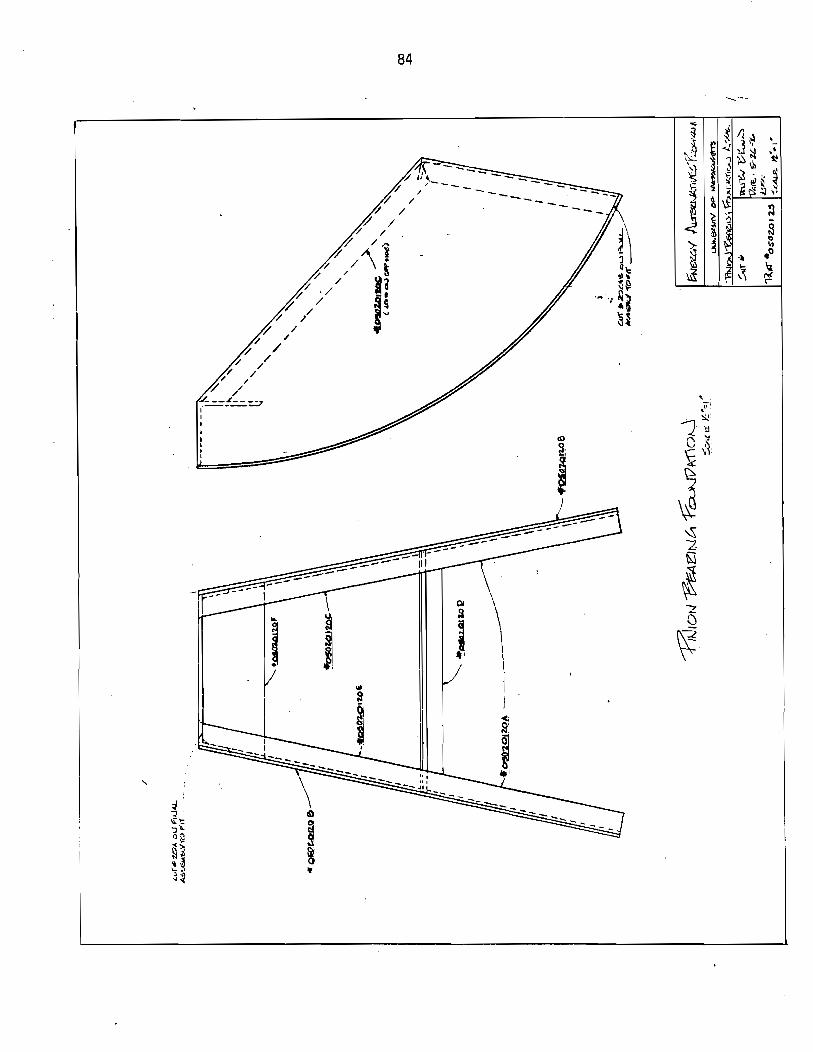
The main frame, w i t h the p o s i t i o n o f t he t r u c k a x l e p i n i o n
s h a f t above the center o f the polematcher, has a l ready been
explained. WF-4 begins i t s change from WF-1 when the t ruck
p i n i o n s h a f t i s r o t a t e d down 90". When t h i s i s done, one f i n d s
t h a t a l though the s h a f t a x i s i s i n l i n e w i t h the l a t e r a l a x i s
off the center o f the polematcher, the shaf t a x i s i s d isplaced
about 1%" away from the l o n g i t u d i n a l ax is . This i s the
c h a r a c t e r i s t i c o f the hypoid gear d r i ve . One s o l u t i o n i s t o
angle the shaf t toward the ho le i n the polematcher, press the
f i r s t bearing s e t i n t o the top o f the polematcher, b r i ng a
s h a f t up through t h a t bearing w i t h a sp l ined end and a t tach
the p i n i o n s h a f t t o t h a t v e r t i c a l s h a f t w i t h one constant
v e l o c i t y un iversa l j o i n t . Another s o l u t i o n would be t o drop
the p i n i o n s h a f t s t r a i g h t down and use a shor ter shaf t w i t h
twohooketype un iversa l j o i n t s t o connect the p i n i o n t o the
ground shaf t . With t h i s method, the f i r s t s h a f t bearing may
have t o be placed lower i n t o the polematcher i n order t o ga in
s u f f i c i e n t clearance f o r the un iversa l j o i n t s and sp l ined
coupl ing. With e i t h e r system a sp l ined s h a f t i n t e r f a c e would
be requ i red a t the p o i n t where the tower and polematcher are
fastened. I n order t o counter the yawing torque induced by
the ground shaf t , a yaw d r i v e r , poss ib ly o f a worn gear type
should be used.
Running the ground shaf t through the l eng th o f the tower
would be done i n s t a t i o n s cons is t i ng o f one shaf t , two un iversa l
Page 46
j o i n t s and one bulkhead bearing. The leng th of each s t a t i o n
i s determined by a c a l c u l a t i o n which determines the resonant
frequency i n s h a f t w h i r l . Shaft w h i r l i s an unstable v i b r a -
t i o n cond i t i on which would impose h igh loads on t h e shaf t ,
s h a f t bearings and un iversa l j o i n t s causing them t o f a i l
prematurely. Using a nominal p ipe o f 1.66 OD and 1.20 ID,
each s h a f t s t a t i o n must be no more t h a t 7 f e e t apart . The
c a l c u l a t i o n was done using an equat ion f o r s h a f t w h i r l , t he
above torque tube and the p i n i o n ra ted rpm. I f sha f t i ng
were des i red i n a basement 68 f e e t from the wind axis , 68/7
o r 10 bearing s t a t i o n s would be requ i red .
To i n s t a l l t he s h a f t i n g i n the tower, one method would
be t o b u i l d the shaf t ing , bearings, and un iversa l j o i n t s
ou ts ide the tower. The bearings would;)be fastened t o bu lk -
heads whose exact p o s i t i o n s would be located on the tower.
The bulkheads would have two threaded ends 180" apart , exact
b o l t holes would be located on the tower and then the bulk-
heads fastened ins ide . Alignment i s n o t c r i t i c a l because of
t he f l e x i b i l i t y o f f e r e d by t h e un iversa l j o i n t s . The e x i s t i n g
WF-1 has a p rov i s ion o f b r i ng ing the shaf t i n t o a sho r t
tunnel beneath the tower 's base. Here another 90" speed
d i f f e r e n t i a l could be used t o b r i n g the s h a f t power away from
t h e tower and i n t o whatever power receptor i s desired.
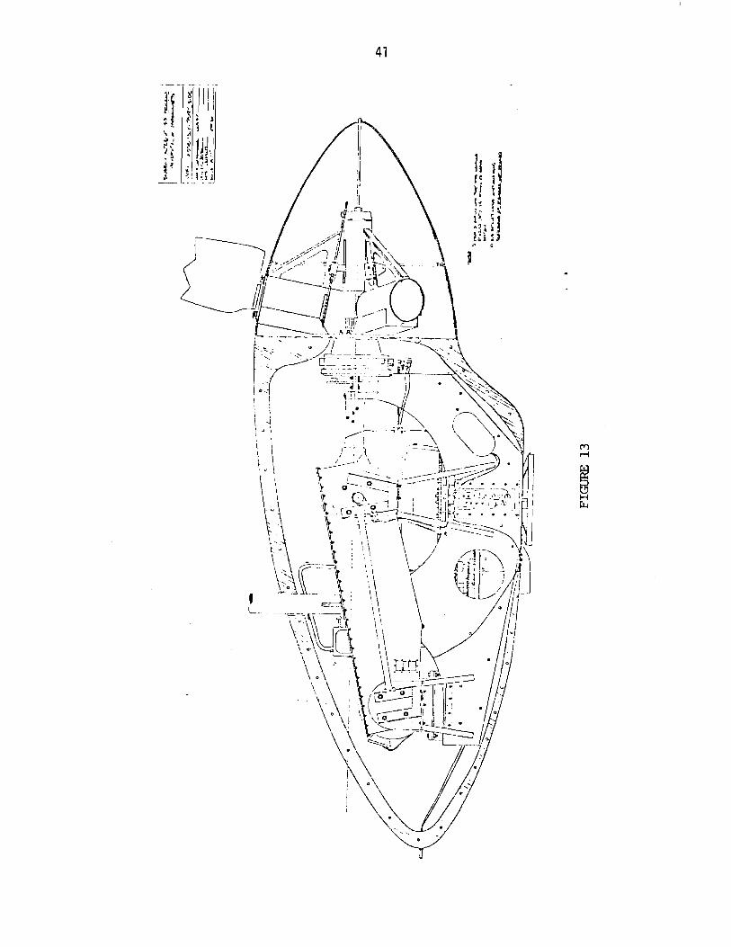
b. Wind Furnace-1 (WF-1)
The arrangement f o r WF-1 i s shown i n Figures 13 and 14.
Here, s h a f t work from the wind r o t o r tu rns hypoid gears w i t h
a step up r a t i o o f 4.86 t o 1. That ou tput shaf t d r i v e s a
Page 49
se t of s i l en t chain sprockets with a step-up ra t io of 2.22
to 1, which i n turn drives the 25 Kw generator. For t h i s
design, the ent ire power unit i s enclosed in the WF-1 nacelle
and energy transferred to the ground by transmission lines.
The design considerations discussed here were the modifica-
tion of the truck rear axle and the selection of a second
stage speed drive.
In order to be able to use the truck axle, three experi-
ments would have t o be successfully completed. The truck axle
shaft i s a sol id, specially heat treated steel alloy w i t h an
OD of 1.35. The design for the WF-1 variable blade pitch
requires a 5/8" diameter clearance through the center length
of th i s axle. The problem i s to d r i l l t h i s hole accurately
for i t s 36" length. The next problem was to determine whether
or not the different ial gears could be successfully locked,
providing us with a 90° hypoid gear box. The final task was
to ensure structural integrity of the complete axle assembly.
To answer these questions a used, one ton, rear axle
assembly was purchased, taken apart, and studied. A 5/8" hole
was successfully dr i l led the ent i re length of the axle shaft
even though the steel hardness did make the task more d i f f i cu l t ,
and the different ial gears were successfully locked. After
applying the estimated rated and weight loads of the wind
turbine t o t h i s axle assembly, i t was found that the spindle
upon which the windrotor turns was s tructural ly inadequate and
the shaft torque carrying capabi 1 i ty was questionable. A
Page 50
sl ight ly larger rear axle assembly was investigated and
purchased new. Figure 15 shows the truck axle exploded view.
An analysis was conducted on th i s rotor spindle using as loads
the rotor weight and moment due to angular momentum of the
spinning rotor. I t was found that the highest stressed point
on the spindle carr ies a safety factor of three. The differen-
t i a l gears were locked and th i s procedure appears in Appendix
1 1 The design torque carrying capability of the hypoid ring
gear was compared to the rated w i n d rotor torque of 1572 f t -
Ib s . A l e t t e r received from the gear manufacturer s ta tes a
continuous rating of 1750 f t - lbs and a maximum rating of
7000 f t - lbs . A s t i l l questionable area of strength i s the
wind rotor shaft .
To determine i t s structural integri ty, a non-destructive
hardness t e s t was conducted and information was gathered from
the manufacturer concerning metal type and hardness.
The two widely used methods for determining steel hardness
are the Brinell and Rockwell standards. I t was learned t h a t a
hardness of Rockwell C48 existed a t the surface and C20 from
.15" to .24" below the surface. Although there i s no direct
relationship between hardness and yield or tensil strength of
s t ee l , a useful correlation does exis t between the hardness of
a material and the tensil strength, endurance l imit , and wear
resistance. The tensil strength of steel i s usually about
500 times the Brinell Hardness number.* A Rockwell C48
* Ref. # I . , p. 580.
Page 51
I 1109
IFROM SERIAL F\O,OOl]
Page 52
corresponds t o a Brine11 460, using the approximation, the
shaft surface can wi thstand about 230,000 p s i o f s t ress .
This was v e r i f i e d by the ax le supp l i e r who s ta tes a working
t e n s i l s t rength o f 232,000 p s i . Because the ma te r ia l below
the sur face i s no t as hard, i t would be expected t h a t t he
s h a f t t e n s i l s t rength i s less. There i s no c o r r e l a t i o n
usua l l y between t e n s i l and y i e l d s t rength o f a ma te r ia l , bu t
a f t e r inspect ing the trends o f o ther hardened mate r ia l s and
p i c k i n g the worst cases t h e y i e l d s t reng th i n shear o f t h i s
shaft was est imated a t 90,000 p s i even though the supp l i e r
s ta tes t h e y i e l d s t ress a t 125,000 p s i . The wind r o t o r
torque would put a s t ress o f 45,000 p s i on t h i s shaf t , there-
fore, an est imated sa fe ty f a c t o r o f 2 i s present. During t h e
s h a f t ' s t ime i n opera t ion i t s torque has been increased t o
1.5 t imes t h e r a t e d value. When the machine was taken down
f o r overhaul, t he s h a f t was inspected and the re was no e v i -
dence o f permanent y i e l d . Because the s h a f t would be run
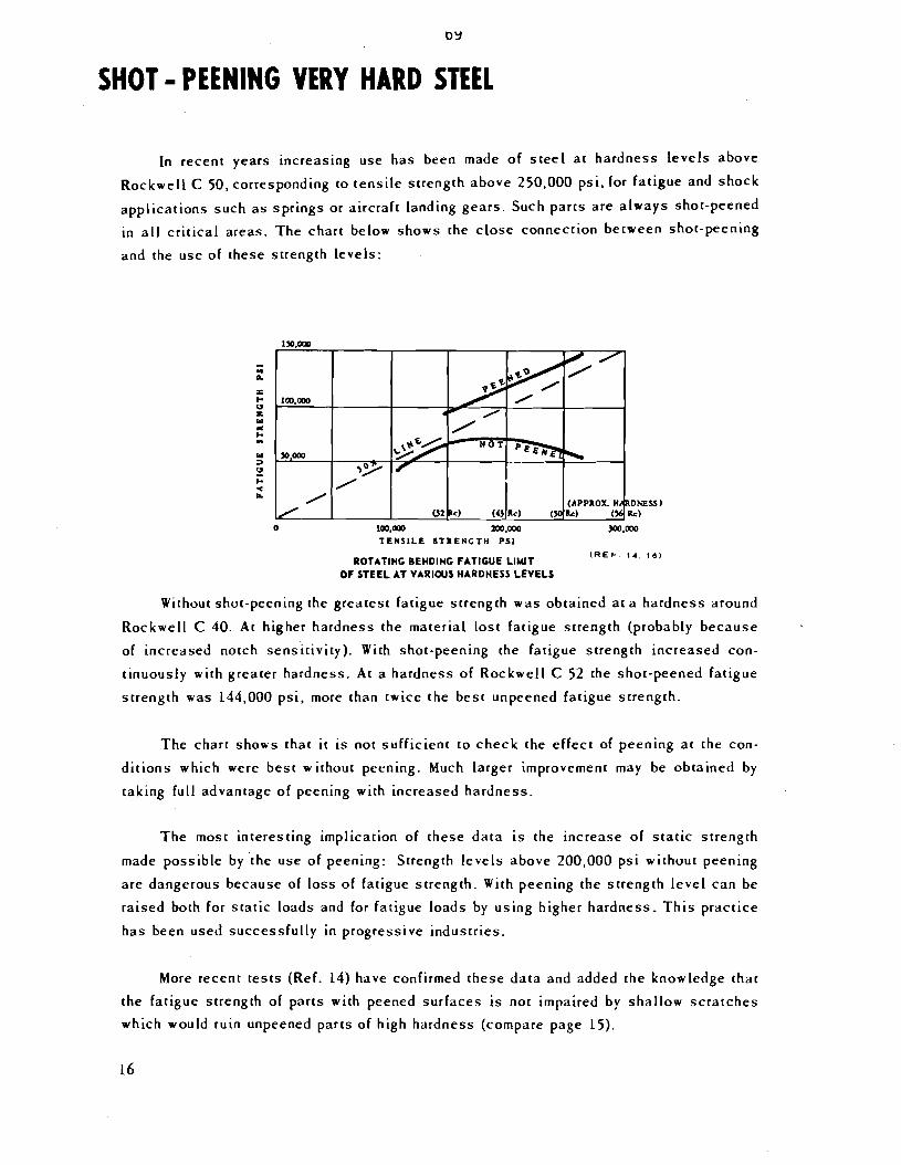
a t h igh c y c l i c loads, i t was decided t o have the shaf t shot
peened. Shot peening a s tee l s h a f t o f t h i s hardness has an
e f f e c t o f increas ing the f a t i g u e endurance l i m i t by a f a c t o r
o f two. A reference subs tan t ia t i ng t h i s appears i n the
Appendix. I n order t o moni tor s h a f t torque a se t o f s t r a i n
gages were permanently attached t o the windshaf t along w i t h
s l i p r i n g s . This was done so t h a t s h a f t torque could be
monitored d i r e c t l y and over s t ress ing prevented.
Although the t ruck a x l e i s being modi f ied f o r the wind
tu rb ine , t r o u b l e was taken t o mount and operate the assembly
Page 53
i n the WF-1 i n the same normal manner as i t would on an
ac tua l t ruck . So the a x l e does s i t i n an u p r i g h t manner and
the hub r o t a t i o n corresponds t o a forward veh ic le niotion.
The p r i n c i p l e o f the d r i v e corresponds t o the veh ic le r o l l i n g
downhi l l us ing the engine and a lower gear f o r decelerat ion,
so energy i s f l ow ing i n t o the d r i v e ins tead o f out . With these
r e s t r i c t i o n s and the f a c t t h a t the blades r o t a t e clockwise
look ing downwind, then the t r u c k wheel hub t o which the machine
hub and blades were fastened was the l e f t o r d r i v e r ' s s ide o f
the veh ic le .
Continuing on w i t h the power transmission design, a second
stage speed d r i v e was required. A main concern here was f o r
t h a t o f an e f f i c i e n t d r i v e , f o r t h a t reason a V-be l t d r i v e
was n o t chosen. Timing b e l t was considered but could no t be
used because a d r i v e o f s u f f i c i e n t power capac i ty was not
ava i l ab le . The choices were narrowed t o a gear box, r o l l e r
chain, o r s i l e n t chain d r i v e . S i l e n t chain costs more than
r o l l e r chain, bu t when f i t t e d t o the WF-1 app l i ca t i on , r o l l e r
chain would experience a reg ion o f g a l l i n g which causes the
chain t o wear a t an increased ra te . The unique design o f
s i l e n t chain i n h i b i t s g a l l i n g , making i t a b e t t e r choice. A
gear box d r i v e was selected, bu t found t o have an expense
th ree times t h a t o f s i l e n t chain; hence s i l e n t chain became
the accepted choice. Along w i t h the acceptance o f t he s i l e n t
chain was the requirement f o r a l u b r i c a t i o n system. The main
considerat ions here were t h a t o f sea l ing the case from o i l leaks,
and t o keep t o a minimum the l a t e r a l w id th o f the machine.
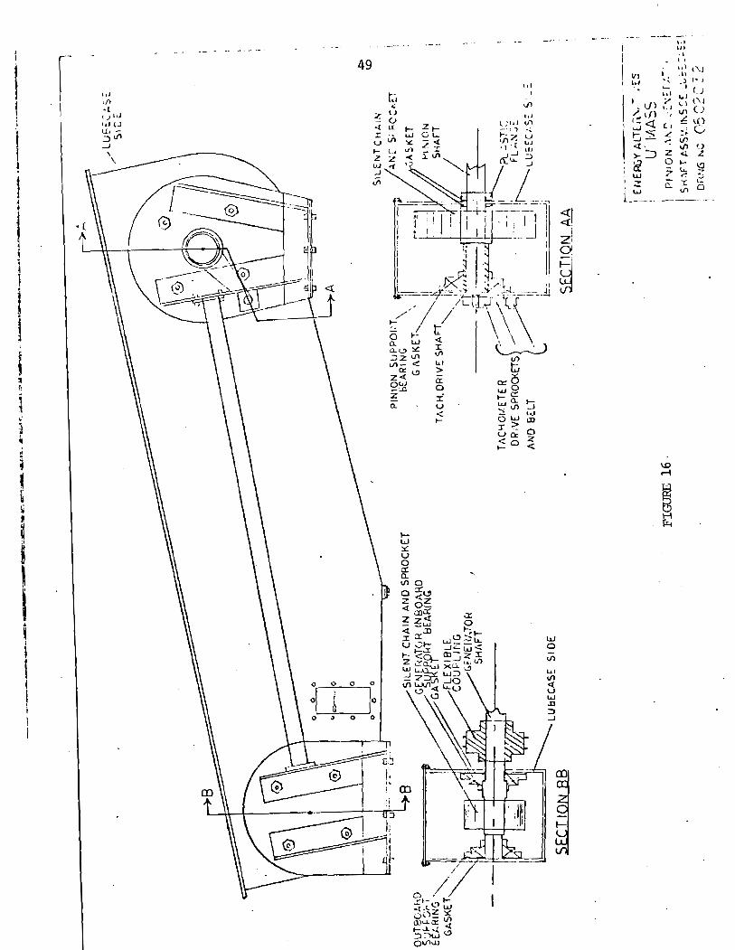
Page 54
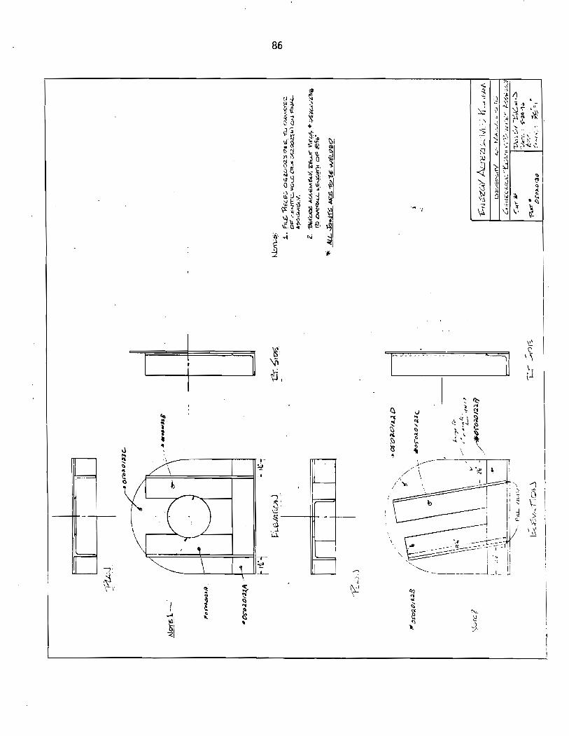
Figure 16 shows t h e d e t a i l o f l u b e case assembly. The
bear ings used used, a l l have t h e i r own o i l sea ls so no o the rs
were requ i red . Throughout t h e bench t e s t i n g and up t o t h ree
months a f t e r WF-1 was i n s t a l l e d , t h e seal f unc t i oned c o r r e c t l y .
A f t e r t h a t t ime, one seal began t o leak, b u t soon co r rec ted
i t s e l f.
2. Cons t ruc t ion
The f i n a l asserr~bly has been shown i n F igures 13 and 14.
The t r u c k a x l e assembly was seated i n t o f i b e r g l a s s and epoxy
r e s i n s a t t h e main frame saddles. Th is was done t o dampen
v i b r a t i o n s be ing t r a n s f e r r e d f rom t h e r o t o r . Other m o d i f i -
c a t i o n s were made o f t h e r e a r a x l e assembly f o r t h e purpose
o f v a r i a b l e b lade p i t c h . These m o d i f i c a t i o n s were n o t conlplex
and a r e descr ibed i n another r e p o r t , "Design o f Hub and P i t c h i n g
System f o r t h e Wind Furnace I", UMass, June 1977. The f o l l o w i n g
paragraphs d iscuss those assemblies which a r e n o t obv ious l y
shown through t h e des ign drawings.
One major t ime consuming task was t h a t o f p a r a l l e l i n g and
t r u i n g t h e s i l e n t cha in sprocke t s h a f t s w i t h respec t t o each
o the r . Th is was done us ing a recommended procedure supp l ied
by t h e manufacturer o f t h e sprockets and t h e guidance o f t he
eng ineer ing depar tment 's machine shop foreman. The bas i c pro-
cedure e n t a i l e d t r u i n g t h e s h a f t s us ing d i a l i n d i c a t o r s ,
l e v e l i n g w i t h a s tandard f l u i d l e v e l and p a r a l l e l i n g by
c o n s t r u c t i n g r i g h t angles f rom t h e s h a f t ax les and s e t t i n g
an exac t d i s tance o f 41 3/4" between t h e s h a f t ends. The
41 3/4" i s t h e recommended s h a f t c e n t e r l i n e d is tance , which
Page 56
50
was c lose enough t o the designed 42". S i l e n t chain, by design,
a1 lows f l e x i b i l i t y i n c e n t e r l i n e d is tance o f up t o an inch,
there fore , the s h a f t cen te r l i nes are n o t adjustable. Another
major task was t h a t o f b u i l d i n g and f i t t i n g the p in ion shaf t ,
F igure 17. Although the s h a f t could have been b u i l t i n one
piece, two separate sect ions, the sp l i ned assembly and the
shaf t body were b u i l t and welded together . The p o i n t a t which
the two were welded i s on the 3%" s h a f t body, 4" away from
the s p l i n e assembly. The s p l i n e diminsions were measured
d i r e c t l y from the male d i f f e r e n t i a l sp l ines. A problem was
encountered when f i t t i n g the p i n i o n sprocket s h a f t t o t h e
d i f f e r e n t i a l p in ion . Apparent ly the bearing surfaces w i t h i n
the d i f f e r e n t i a l were s l i g h t l y cocked from a v e r t i c a l plane
p a r a l l e l w i t h t h e l o n g i t u d i n a l ax is , causing a s h a f t runout
o f + . 0 l U . To remedy t h i s , index marks were used t o match the
same sp l ines and the seat o f t he sp l ines was hand f i l e d t o a
p o i n t where the int roduced e r r o r o f f s e t the d i f f e r e n t i a l bearing
e r r o r . The s h a f t runout was even tua l l y reduced t o * ,002". The
f o l l o w i n g i s the procedure used t o complete the cons t ruc t i on o f WF-1.
A l l bearings used were s e l f - a l i g n i n g and modi f ied by tack
welded mounting nuts t o the i n s t a l l a t i o n holes. This was done so
t h a t i f the nut were t o loosen, i t could n o t f a l l i n t o the lube
case and so t h a t t he bearing fasteners could be t igh tened wi thout
having t o remove the lube case cover. 'The e n t i r e d r i v e was assembled
using l a r g e C-clamps as fasteners w i thou t the lube case so t h a t t he
shaf ts could be pos i t ioned and t rued. The exact b o l t holes were
d r i l l e d and those holes t rans fe r red t o the lube case. I n the f i n a l
assembly the p i n i o n sprocket s h a f t was bo l ted t o the d i f f e r e n t i a l
p in ion .
Page 58
Next,the gaskets, sprocket, bearing, lube case, and bear ing
suppor t were s l i d i n t o t h a t s h a f t a t one t ime. A l l b o l t s
and s e t screws were p u t i n t o p lace, b u t n o t fastened down
complete ly . A t t he generator end, t h e bear ing supports,
gaskets and bearings were l o o s l y fastened i n t o p lace, and
then the generator ex tens ion s h a f t s l i d through the bear ings
and i n t o t he generator sprocket . A f i n a l s h a f t runout was
checked and a l l f as ten ings were t igh tened. The generator
was brought i n t o p lace and shimmed t o a l i g n i t s s h a f t w i t h
t h e generator ex tens ion sha f t , then a r o l l e r cha in coup l i ng
was added. I n i t i a l l y a r i g i d coup l i ng was used, b u t due t o
t h e f a c t t h a t some v i b r a t i o n was present , i t g o t h o t and so
a dec i s i on was made t o use t h e f l e x i b l e cha in coupl ing. The
s i l e n t cha in was i n s t a l l e d and type "A" automatic t ransmiss ion
f l u i d added t o a l e v e l where through t h e s i g h t g lass , c o n t a c t
was made w i t h t he c h a i n ' s lower s t rand; about 9 quar ts . Two
and one h a l f quar ts o f hypoid gear o i l was added t o t he t r u c k
d i f f e r e n t i a l . The l ube cover was added, a s i de s t r u t i n s t a l l e d ,
and the machine was ready f o r t h e bench t e s t s .
3. B i l l s o f M a t e r i a l and Cost.
The f o l l o w i n g i s t h e b i l l o f t ransmiss ion m a t e r i a l s and
costs . The p r i c e s r e f l e c t l a t e 1975 costs .
Page 59
BILL OF MATERIAL - WIND FURNACE REV, 8/10/77
WORKING GROUP GF= R I I - ~ F SHEET NO. 2 of 2
ITEM
05020321 .15
.16
.17
-18
-19
I ESTIMATED
$9.00
$13.86
$5.50
$2.15
$3.08
SOURCE
HOOKER TRANSMISSION
11
II
II
II
DESCRIPTION
GENERATOR EXTENSION SHAFT w i th DOUBLE STRANDED CHAIN, (Type 50B18) DIFFERENTIAL HYPOID SYNTHETIC GEAR01 L
(90-140~) TACHOMETER DRIVER SPROCKET, (42XLB037) 1/5" P i tch x 9/16'' wide,42 teeth TACHOMETER DRIVER SPROCKET, (lOXLB037)
9/16" wide. 10 TACHOMETER DRIVE BELT, (180xLB037 ) 1/5" Pi tch x 3/8" wide
1000 COST
VI W ,
1
I
*
QUANTITY
2
? qc
1
II
In
1
Page 60
BILL OF MATERIAL - WIND FURNACE WORKING GROUP G F ~ Y & I SF SHEET NO. of
nRWNG< : fI5n?nB?I " ...... -- L
ITEM 05020321
.01
.02
n3
ESTIMATED'
$30.00
$4.00
$4.00
$92.69
$177.19
$187.00
$3.14
$7.10
$16.00
$48.03
$29.57
$25.35
nn
$10.00
SOURCE
SHOP
HOOKER TRANSMISSION
. -------- DESCRIPTION
SILENT CHAIN LUBRICATING CASE
SHAFT OIL SEAL, 2.5" D iameter
I1 I1 , 2" I1
RAMSEY SILENT CHAIN SPROCKET, 3 1 Tee th
1000 COST '
cn P
3
1
.w
QUANTITY
1
2
2
1
It
-
2 SETS
10 q t s .
46 C A I A ~ ~ - -
1,
I1
I1
II
2
.04
.05
.06
.07
.08
09
1311 P i t r 1 7/811 JILENT CHAIN SPRO 69 Teeth, 3 " Bore, 1 1 2 x1 /4 keyway SILENT CHAIN CENTER GUIDE
1/2" P i t c h x 3" wide
CONNECTING LINKS FOR SILENT CHAIN
LUBE O I L FOR SILENT CHAIN, (Type A a t f )
TS FOR I I W C F 3/16"
. l o PINION SUPPORZ BEARING, (Type FB-350-2.5"; I (Type FB-350-2")
.ll :ENERATOR BEARING INBOARD SUPPORT (Type FB-350-1.75)
.12 II " OUTBOARD I'
.13 PINION EXTENSION SHAFT
ENERATOR I' I1
I#
II
11
uKDWrVrlVG HOOKER TRANSMISSION
I1
II
SHOP
I t
Page 61
BILL OF MATERIAL - WIND FURNACE REV, 8/10/77
WORKING GROUP REAREND SHEET NO. DRWNGS
h
ITEM
, 01
, 02 050301 05
.O1
.O1
SOURCE u s o 3 m 0 T T 7 r I v m m T ~ - - -
WORCESTER ,MA.
II
I 1
SPENCER BROS. NORTHFIELD,MA.
: 05030104,05030105,05030110
DESCRIPTION
BALL SCREW BEARING LOCKNUT (NO6 Locknut )
BALL SCREWBEARING LOCKWASHER I I .I
7706 RII U l a r Ijlnt.ar.t.- DANA SPICER REAR AXLE ASSEMBLY
(4.86: 1 Speed Ratio)
QUANTITY
1
I 1
2 @ 7.07 ea.
1
I ESTIMATED
$0.45
$0.11
$14.14
$328.00
-
1000 COST
VI 0,
-
I
4
Page 62
V I . BENCH TESTING
For the purpose o f the bench t e s t s , the completed wind t u r b i n e
was bo l ted t o the f l o o r o f the t e s t l a b and connected t o a 150 HP Ford
d iese l engine. The energy from the d iese l was t ransmi t ted t o the wind
s h a f t by way o f a torque pickup, extension shaf t , and un iversa l j o i n t s .
The purpose o f these t e s t s were t o a l low a c o n t r o l l e d break- in per iod
f o r the new mechanical par ts , t o i s o l a t e and c o r r e c t undesi rable opera-
t i o n a l c h a r a c t e r i s t i c s of the f i r s t and second stage dr ives , and f i n a l l y ,
t o determine the o v e r a l l d r i v e e f f i c i e n c y .
The t e s t s f i r s t began i n August. A t t h i s t ime the s t a t i c torque
requ i red t o begin the machine t u r n i n g was 52 f t - l b s . A f t e r the complet ion
o f the t e s t s and some 30 hours o f operat ion, t h i s torque value decreased
t o 27 f t - 1 bs. I t i s expected t h a t under normal cond i t ions t h i s value w i 11
decrease s l i g h t l y , bu t i n co lder weather, the th icken ing o i l may increase
it. A f t e r the i n i t i a l runs, t he r i g i d coup1 i n g connecting the second
stage speed d r i v e t o the generator was replaced w i t h a f l e x i b l e one. Th is
n o t on l y solved the heat ing problem, bu t reduced the d r i v e v i b r a t i o n almost
t o nonexistance. O i l leaks were detected along the top o f the o i l case
and around the f i b e r g l a s s f lange located a t the d i f f e r e n t i a l housing. By
the end o f the t e s t period, a l l o i l leaks had been f i x e d except f o r the
one a t the d i f f e r e n t i a l f iberg lass flange. The leak progressed a t about
4 drops/hr, and was determined t o be t o l e r a b l e . Th is problem can be
corrected, i t was thought l a t e r , by the a d d i t i o n o f a splash boot connected
i n s i d e the lube case. I t was mentioned e a r l i e r t h a t al though no o ther
leaks developed on the t e s t stand, a f t e r th ree months i n operat ion, a l eak
d i d develop a t the inboard generator sprocket bearing, bu t a f t e r more t ime
i n serv ice, t h i s problem cor rec ted i t s e l f .
Page 63
During the t e s t , i t was found t h a t under f u l l load, the o i l temp-
e ra tu re i n the d i f f e r e n t i a l rose t o 250" F. It should be noted t h a t
u s u a l l y these d i f f e r e n t i a l assemblies are mounted t o moving veh ic les and
t h a t motion creates a coo l i ng breeze. For the WF-1, two th ings were done
t o c o r r e c t t h i s . A p o s i t i v e v e n t i l a t i o n system was i n s t a l l e d and the
conventional hypoid gear o i 1 rep1 aced w i t h a syn the t i c type having many
t imes the f i l m st rength. The v e n t i l a t i o n system e n t a i l e d i n s t a l l i n g
r a d i a l f i n s t o the w indro tor i n between the s t a t i o n a r y and r o t a t i n g
nacel les. A vent hole was d r i l l e d from the i n s i d e o f the main nace l l e
i n t o t h a t area and a ram a i r duc t fastened near the tower on the bottom
o f the main nace l l e fac ing upwind. I n the lab, the syn the t i c o i l reduced
the temperature by 30°F over the conventional gear o i l , and once i n s t a l l e d the
v e n t i l a t i o n system w i l l a lso y i e l d a con t r i bu t i on . I t should be considered
t h a t al though the bench t e s t was conducted a t a f u l l continuous load,
the wind t u r b i n e w i l l operate a m a j o r i t y of the t ime a t a p a r t i a l load.
Therefore, the heat bu i ldup r a t e w i l l be less . A l l t h ings considered, no
problem i s now expected i n t h i s area. The d r i v e e f f i c i e n c y was determined
by measuring i n p u t torque and speed and comparing t h a t t o generator ou tput
Kw f o r d i f f e r e n t speeds. From these comparisons, the d r i v e e f f i c i e n c y
i n c l u d i n g generator e f f i c i e n c y was found t o be 82%. The bench t e s t s were
completed i n October, 1976 w i t h the mechanical d r i v e accepted f o r f u l l -
ra ted operat ion.
Page 64
V I I FUTURE CONS1 DERATIONS
As t h e b u i l d i n g o f t h e wind t u r b i n e progressed, m o d i f i c a t i o n s o f
t h e o r i g i n a l designs were brought up and u s u a l l y incorpora ted i n t o t he
e x i s t i n g machine. Some s p e c i f i c mod i f i ca t i ons were e i t h e r r e a l i z e d t oo
l a t e i n t h e b u i l d i n g stage o r learned from the f i n i s h e d product, i n which
case, they cou ld n o t be incorporated. Some s p e c i f i c cons idera t ions a re
discussed below.
A. S l i p r i n g Assembly
By reduc ing t he s i z e of t h e l a r g e s l i p r i n g s ; more, b u t
sma l le r r i n g s would be a v a i l a b l e . The brush b locks should be redesigned
t o f i t i n s i d e t h e s l i p r i n g housing p o s s i b l y on i n s u l a t e d pos ts screwed
i n t o t h e main frame base. A new brush of r ec tangu la r shape cou ld be
used t o achieve t h e same brush t o s l i p r i n g con tac t area. The advantage
would be more s l i p r i n g s , e a s i e r i n d i v i d u a l adjustment o f brushes, and
b e t t e r p r o t e c t i o n of t he brush ho lders which would be t o t a l l y enclosed
i n s i d e the housing. Much o f t h e s l i p r i n g expense came f rom the bronze
r i n g s having a %." w a l l . Al though t h e expense was l e s s than t h a t o f a
commercial ly a v a i l a b l e s l i p r i n g s tack, a b e t t e r approach would have been
t o r o l l i n d i v i d u a l r i n g s w i t h a 1 / 1 6 " w a l l i n t o hoops, b raz ing t h e ends
together . Th i s would l ead t o a l i g h t e r , sma l le r and cons iderab ly l e s s
expensive assembly. There would be an est imated savings o f 80%.
B. Main Frame.
Using 1/8" s t e e l p l a t e would be a savings i n we igh t and c o s t
w i t h very l i t t l e s a c r i f i c e i n s t r u c t u r a l i n t e g r i t y . I ns tead o f cont inuous
welds, spaced 2" t ask welds cou ld have made t h e f a b r i c a t i o n l e s s expensive.
The present frame was b u i l t w i t h a l a r g e sur face area so t h a t t h e f as ten ing
Page 65
of o t h e r machine accessor ies and supports would be made eas ie r . Now
t h a t t h e l o c a t i o n o f s p e c i f i c components a r e i d e n t i f i e d , a s i r r~p le r
frame us ing s t e e l channel o r I-beams cou ld save weight and expense. It
i s impor tan t t o ment ion t h a t much can be gained by forming a frame o f
f i b e r g l a s s o r wood. Once s p e c i f i c b u i l d i n g techniques a re i d e n t i f i e d ,
t h e i n d i v i d u a l p ieces cou ld be b u i l t w i t h o u t the need o f expensive
machines, ma te r i a l s , and manpower.
C. Transmission
One concern here i s t h e bu l ky s i l e n t cha in d r i v e and t h e
associated o i l leakage precaut ions. The i d e a l d r i v e would be t h e second
90" gear box, b u t now t h a t i s a t l e a s t 3 t imes t h e expense o f t h e s i l e n t
cha in d r i v e . What cou ld be considered though would be a second hypoid
d r i v e s i m i l a r t o t h a t housed i n t h e t r u c k d i f f e r e n t i a l . I t migh t be
poss ib le f o r t h e a x l e manufacturer t o supply o n l y t h e d i f f e r e n t i a l
assembly a t a reduced cos t . Because these p a r t s a re mass produced any-
way, i t i s very p o s s i b l e t h a t t h i s d r i v e cou ld c o s t l e s s than the assoc ia ted
s i l e n t than d r i v e . I t i s p o s s i b l e t h a t t h e redes ign f o r such a d r i v e
would inc rease t h e he igh t o f t h e wind a x i s above t h e polematcher. b u t i t
would decrease the l a t e r a l w id th o f t he machine s i g n i f i c a n t l y . Probably
t h e g r e a t e s t headache though was t h e quest ioned s t r u c t u r a l i n t e g r i t y o f
t h e main wind sha f t . A l though a s a f e t y f a c t o r o f two i n y i e l d and even
g r e a t e r i n f a i l u r e was assigned, i t was n o t determined through d i r e c t
eng ineer ing ana l ys i s . Much was dependent on t he m a t e r i a l hardness and/or
assumptions. Because t h e s h a f t was being operated a t such h i g h s t resses,
a c e r t a i n uneasiness was l e f t w i t h many o f t h e p r o j e c t engineers. The
sha f t has shown i t s s t r u c t u r a l i n t e g r i t y i n h i g h instantaneous loads, b u t
t ime i s s t i l l r e q u i r e d t o determine t h e res i s tance t o f a t i g u e . It i s
recommended t h a t sa fe ty f ac to rs of a t l e a s t f i v e be used i n f u t u r e des igns.
Page 66
V I I I . CONCLUSION
It i s now 19 months s ince WF-1 was pu t i n t o operat ion. I n t he
18 th month the machine was brought down f o r a general overhaul. The
generator coup l ing had f a i l e d and has been replaced w i t h a b e t t e r one.
Also,the s l i d i n g mot ion o f the p i t c h l i nkage through the wind s h a f t
acted l i k e a pump, f o r c i n g the d i f f e r e n t i a l lube o i l ou t i n t o t h e nace l l e
spinner. This has been connected w i t h an o i l seal arrangement i n the
nace l l e spinner. I t has been ca l cu la ted t h a t i n an overspeed cond i t i on ,
wind s h a f t torque rose t o 1.5 t imes t h e ra ted value and when t h a t s h a f t
was l a t e r inspected, t he re was no evidence o f permanent y i e l d along i t s
36" length . Because o f the safety f a c t o r o f 2, the l a c k o f damage t o
t h e wind s h a f t seems t o i n d i c a t e no adverse torque t r a n s i e n t s through-
o u t t h e power t r a i n dynamics. Other minor problems were present, bu t
they d i d n o t hamper t h e operat ion. During the 18 nionths o f operat ion,
use fu l energy had been ex t rac ted from the machine and w i t h t h e m o d i f i -
ca t i ons t o those problem areas mentioned above, i t w i l l cont inue t o
operate e f f e c t i v e l y . The WF-1 i s making a c o n t r i b u t i o n t o the f i e l d
o f windpower, by t h e f a c t t h a t i t does i t s j o b w e l l . I t i s by no means
a p e r f e c t machine, b u t i t i s exempl i fy ing many d i f f e r e n t designs and
concepts, some o f which being presented by t h i s repo r t . I t i s hoped
t h a t t he reader can use t h i s r e p o r t as a bas is i n h i s own wind t u r b i n e
design. He w i l l make t h e dec i s ion on whether a c e r t a i n concept i s sound
o r no t and then incorpora te t h a t toward what he fee ls i s a b e t t e r design.
The u l t i m a t e goal i s t o make wind energy a commercial energy source;
t h i s p r o j e c t i s a small s tep i n t h a t d i r e c t i o n .
Page 67
APPENDIX I
Weights and Moments
Page 68
REFEKE).;CE FOR LEVEQ A R M S
i 1 - ' . :.EFT.! F O ~ C j LEVEX I !:~:.:~i(-j( LEVER
1 /MAIM FRAME 1.32 2 ! - 7 1-22591 9 Y
Page 69
ITEM
\ :~RT.! ','ZET.~ FOZE i FO?D l s T @ D SW- LEYER j ::'J:.:sE: TI LEVER ()~;;;E::T I L E Y E R FOXEIII
Page 70
- s
1 - _ _ - - _ __-.--- .-- _ .
FORD 1 3 - w ~ P ~ D :.s:;:::T LEY ER I.:C)GEtl
ITEM A-l'=- ,
-
5 ~ / m n / / M G Co//E (3 GAL. )
0
7~ei5?R/u~7 /s s/od FL I j /a /5 -3%-5h 131 qb5 -14%-221
I WI&E ;', ~ j J I C ~ , ~ ~ / ' i : ~ p j ~ l ~ - p j 7 l : )TJ
p~: , j / ? E X T P ~ gars, E ~ C
OF GRAVI-TY D\ R E < T \ ~ ~ P ,r*- p c VA~;*[ --n~1'~ 1 F> ER
~ P K ~ X K E T (INCHES]
A , - 0 2
9 42< --.
-
0
$ . Y 7 h
J E X T
- ----.
--
/ I a
34744
I
o
-.-.22
2 2 -70 Y
o
- 0.13 .- -- Al= 7-
-- L
-4Q
- - -
I
-- ---- ---
-
o o
-
-1.41
PORT
- w -
-356)
-
-
Page 71
APPENDIX I1
Locking the Truck Differential
Page 72
Locking the Truck D i f f e r e n t i a l
Th is procedure pe r ta ins on ly t o the l o c k i n g o f t h i s p a r t i c u l a r
t r u c k d i f f e r e n t i a l s ince there i s a v a r i e t y o f d i f f e r e n t t r u c k d i f f e r e n t i a l
gear assemblies, and f o r each a unique lock ing method required. Reference
t o Figure 15 and i t s numbered p a r t s are made.
D i f f e r e n t i a l gears No. 4215 were s e t up t o mesh w i t h gears No. 4236
so t h a t t he t o o t h o f gears 4215 was s t r a i g h t up and down w i t h i n the v a l l e y
o f gears 4236. The adjacent va l l eys o f gears 4236 were completely f i l l e d
by consecutive passes o f a welding rod, f o u r va l l eys per gear. Th is r e -
s t r i c t e d the gears from meshing a t a l l . Next, p i n 4211 was replaced w i t h
two studs, one end threaded i n t o d i f f e r e n t i a l assembly 4204 and locked by
se t screws. The o the r end had a ho le d r i l l e d and tapped; a b o l t and washer
l a r g e enough t o r e t a i n gear 4215 was then i n s t a l l e d . The center sec t i on o f
p i n 4211 had t o be removed t o prov ide space f o r the b lade p i t c h i n g l i n k
which passes through the center o f the d i f f e r e n t i a l .
Page 73
SPICER MODEL 6 0 (2 P IN ION) SPICER MODEL 7 0 (4 P IN ION]
FOR "TRAC-LOK" LIMITED SLIP DIFFERENTIAL REFER TO ILLUSTRATION P-8311, PAGE 49 .
6584.5 1 0 0 - 2 1
5 4 8 4 6 - 5 188-242
3 5 4 8 4 5 - 5 IMM-1461
1 @ \ 72071.5
IN -541
FIGURE 15
Page 74
APPENDIX 111
Shot Peening Very Hard Steel
Page 75
O Y
SHOT - PEENING VERY HARD STEEL
In r e c e n t y e a r s i n c r e a s i n g u s e h a s b e e n m a d e of s t e e l a t h a r d n e s s l e v e l s a b o v e
R o c k w e l l C 5 0 , c o r r e s p o n d i n g t o t e n s i l e s t r e n g t h a b o v e 2 5 0 , 0 0 0 p s i , for f a t i g u e a n d s h o c k
a p p l i c a t i o n s s u c h as s p r i n g s o r a i r c r a f t l a n d i n g g e a r s . S u c h p a r t s a r e a l w a y s s h o t - p e e n e d
in a l l c r i t i c a l a r e a s . T h e c h a r t be low s h o w s t h e c l o s e c o n n e c t i o n b e t w e e n s h o t - p e e n i n g
a n d t h e u s e of t h e s e s t r e n g t h l e v e l s :
lW.mO a0o.m TENSILE STRENGTH PSI
ROTATING BENDING FATIGUE L l W T ( R E F . 1 4 . 1 8 )
OF STEEL AT VARIOUS HARDNESS LEVELS
Without s h o t - p e e n i n g t h e g r e a t e s t f a t i g u e s t r e n g t h w a s o b t a i n e d a t a h a r d n e s s a r o u n d
R o c k w e l l C 40 . At h i g h e r h a r d n e s s t h e m a t e r i a l l o s t f a t i g u e s t r e n g t h ( p r o b a b l y b e c a u s e
of i n c r e a s e d n o t c h s e n s i t i v i t y ) . With s h o t - p e e n i n g t h e f a t i g u e s t r e n g t h i n c r e a s e d c o n -
t i n u o u s l y wi th g r e a t e r h a r d n e s s . At a h a r d n e s s of R o c k w e l l C 52 t h e s h o t - p e e n e d f a t i g u e
s t r e n g t h w a s 1 4 4 , 0 0 0 p s i , more t h a n t w i c e t h e b e s t u n p e e n e d f a t i g u e s t r e n g t h .
T h e c h a r t s h o w s t h a t i t i s n o t s u f f i c i e n t t o c h e c k t h e effect of p e e n i n g a t t h e c o n -
d i t i o n s w h i c h w e r e b e s t w i t h o u t p e e n i n g . Much l a r g e r improvement may b e o b t a i n e d by
t a k i n g fu l l a d v a n t a g e o f p e e n i n g wi th i n c r e a s e d h a r d n e s s .
T h e m o s t i n t e r e s t i n g i m p l i c a t i o n of t h e s e d a t a i s t h e i n c r e a s e of s t a t i c s t r e n g t h
m a d e p o s s i b l e by ' the u s e of p e e n i n g : S t r e n g t h l e v e l s a b o v e 2 0 0 , 0 0 0 p s i w i t h o u t p e e n i n g
a r e d a n g e r o u s b e c a u s e of l o s s o f f a t i g u e s t r e n g t h . With p e e n i n g t h e s t r e n g t h l e v e l c a n b e
r a i s e d bo th f o r s t a t i c l o a d s a n d for f a t i g u e l o a d s by u s i n g h i g h e r h a r d n e s s . T h i s p r a c t i c e
h a s b e e n u s e d s u c c e s s f u l l y i n p r o g r e s s i v e i n d u s t r i e s .
More r e c e n t t e s t s ( R e f . 14) h a v e c o n f i r m e d t h e s e d a t a a n d a d d e d t h e k n o w l e d g e t h a t
t h e f a t i g u e s t r e n g t h of p a r t s wi th p e e n e d s u r f a c e s is n o t i m p a i r e d by s h a l l o w s c r a t c h e s
w h i c h would ru in u n p e e n e d p a r t s of h i g h h a r d n e s s ( c o m p a r e p a g e 15) .
Page 76
APPENDIX I V
Remaining P r o j e c t Drawings
Page 77
,"-- - .\ ITEM I -POLE MATCHER STEM
[---y.'-\ ) 5663 l PARf INCN 0 0 NO SCMDULf 4563 0 5 , O L O i G l I 0 120 5 0 0 WALL
GF~AOE A 1 0 6 PIPE
, / -1
- - _ _ --'
, 1 I / ; . UNLESS 0~tlERw1.sE SPECIFIED
2 1/16" FRACTIONAL 2.01' DECIMLL
~ r E , b r - 2 P h r . F A : C / L A ; ;
I ART NC. 0 5 Oa.O?D:'
MILO s r m
_ ._ -_ . . - , . I , IL:,'I.:. .. .h'. I:.C r 7s - . .. -
~.ln~., i-r~; STEM ,vc PLATL- <i T@-- . -. -- - - - - . - - - - - -- -. -. .-
OW4WN B l ;r~~,,-a - ~--- ._ ._ . .-
Page 82
n 0 3 ~ 1 n t m 1 z OF02 OSO Nd
Page 83
I I -
- 18' - TOLERANCES UNLESS OTHERWISE SPECIFIED * 1/16
?I N O V E U B r R 19'5 050201B -- .- . - -. -- -- - - W P Z : Gz.~_
Page 85
~ ---- TCLEHANCES UNLESS tvIdSSkCHU~5E T TS
' 0 THERWISE SPECIF/ED SIDE ::!JWC/riTS
5 / / i c "
SCALE: I/.>
Page 100
. WEf?GY ALTERNAT4E PRCG!?!R U -FIASS
R AR AXLE A'iSEM13LY ~Susmt MoclFlcAT Ims
Page 101
NOMENCLATURE
S-F
p s i
W ECS
i n s i d e diameter
ou ts ide diameter
k i l owa t t s
r e v o l u t i o n s per minute
m i l e s per hour
f r e e w i nds tream vel o c i t y
a i r c l e v i t y
swept area o f a wind r o t o r
r o t a t i o n a l speed of a wind r o t o r
wind r o t o r blade rad ius
safety fac to r
cross sec t i ona l area o f a s t e e l p ipe
pounds f o r c e
pounds per square i n c h
Wind Energy Conversion System
Page 102
BIBLIOGRAPHY
Baumeiste, Theodore, Marks' Standard Handbook f o r Mechanical Engineers , McGraw-Hi 11 , New York, 1971.
B u t t e r f i e l d , Charles B., Jr . , "Design o f Hub and P i t c h i n g System f o r Wind Furnace I (WF-1) ", UMassIAmherst Energy A1 t e r n a t i ves Program, WF/TR/77/4.
Heronemus, W i l l i a m E., " I n v e s t i g a t i o n o f t h e F e a s i b i l i t y o f Using Windpower f o r Space Heat ing i n Colder Cl imates", UMass/Amherst Energy A l t e r n a t i v e s Program, WF/PR/77/1.
Mabie, H. H. and F. W. Ocverk, Mechanisms and Dynamics o f Machinery, John Wi ley and Sons, New York, NY, 1975.
"Morse Power Transmission Products Catalogue", Morse Chain, D i v i s i o n o f Borg Warner Corp. , 1973.
"Shot-Peening Appl i c a t i o n s " , Metal Improvement Company Pub1 i c a t i o n , Four th e d i t i o n .
Spo.tts, M. F., Design o f Machine Elements, Four th e d i t i o n , P ren t i ce H a l l , Englewood C l i f f s , NJ, 1971.
Stoddard, F. S., "Discussion o f Momentum Theory f o r Windmi l ls" , UMass/Amherst Energy A l t e r n a t i v e s Program, TR/76/2.