7.06 MATERIALS AND INSTALLATION........................................................................................................................21
7.07 OPEN DRAINAGEWAYS ............................................................................................................................................21
7.10 STREET DRAINAGE....................................................................................................................................................40
(A) FUNCTION OF STREETS IN THE DRAINAGE SYSTEM ...................................................................................................... 40(B) STREET CLASSIFICATION AND ALLOWABLE RUNOFF ENCROACHMENT ...................................................................... 40(C) HYDRAULIC STREET CAPACITY...................................................................................................................................... 41(D) CROSS STREET FLOW ...................................................................................................................................................... 41
Table 7-2: Runoff Coefficients for the Rational Method......................................................................................................... 18
Table 7-3: Manning's "n" for Storm Sewers .............................................................................................................................. 27
Table 7-5: Standard Inlets ............................................................................................................................................................ 36
Table 7-6: Allowable Street Drainage Encroachment................................................................................................................ 40
Effective: November 16, 2000 DESIGN AND CONSTRUCTION STANDARDS 7-3
Table 7-7: Allowable Cross Street Flow...................................................................................................................................... 44
LIST OF FIGURES
Number Page
Figure 7-1: Rainfall Intensity-Duration-Frequency Curve for the City of Boulder ..........................................................7-17
Figure 7-2: Overland Time of Flow Curves .............................................................................................................................7-19
Figure 7-3: Estimate of Average Flow Velocity for Use with the Rational Method .........................................................7-20
Figure 7-4: Typical Form for Storm Drainage System Design Data ....................................................................................7-30
Figure 7-5: Storm Sewer Energy Loss Coefficient (Expansion/Contraction).....................................................................7-34
Figure 7-6: Manhole and Junction Losses…………………………………………………………..............................7-35
Figure 7-8: Allowable Inlet Capacity, Type ‘R’ Curb Opening on a Continuous Grade..................................................7-38
Figure 7-9: Allowable Inlet Capacity, Type ‘A’ Combination on a Continuous Grade ...................................................7-39
Figure 7-10: Nomograph for Flow in Triangular Gutters.......................................................................................................7-42
Figure 7-12: Design Computation Form for Culverts ............................................................................................................7-45
7-4 DESIGN AND CONSTRUCTION STANDARDS Effective: November 16, 2000
7.01 General
(A) Intent
The Storm Water Design Standards are intended to provide for a comprehensive and integrated stormwater utility system to convey and manage storm waters in order to mitigate safety hazards andminimize property losses and disruption due to heavy storm runoff and flooding, maintain travel onpublic streets during storm events, enhance water quality of storm runoff by mitigating erosion,sediment and pollutant transport, control and manage increased runoff due to local development,establish effective long-term management of natural drainageways, and provide for ongoing andemergency maintenance of public storm water systems.
(B) Storm Water and Greenways Master Plans
All improvements proposed to the City’s storm water system shall conform with the goals, policies,and standards outlined in adopted Storm Water Collection, Major Drainageway, and GreenwaysProgram Master Plans.
(C) Reference Standards
Where not specified in these Standards or the B.R.C. 1981, to protect the public health, safety, andwelfare, the Director of Public Works will specify the standards to be applied to the design andconstruction of storm water improvements and may refer to one or more of the references listed inthe References Section of these Standards.
(D) Floodplains
Where improvements are proposed within a designated 100-year floodplain, as defined on the currentFEMA Flood Insurance Rate Map (FIRM) or floodplain mapping adopted by the City, an applicant forconstruction approval shall satisfy and comply with all applicable regulations and requirements as setforth in Chapter 9-9, “Floodplain Regulation,” B.R.C. 1981.
(E) Storm Water Quality and Erosion Control
The UDFCD’s Urban Storm Drainage Criteria Manual, Volume 3, “Best Management Practices,”“Colorado Department of Transportation M-Standards, and/or City of Boulder, “Wetlands ProtectionProgram Best Management Practices” manual shall be applied to address storm water qualitymanagement and erosion control for all proposed projects and developments. All storm water reportsand plans shall include necessary analyses, mitigation measures, and improvements needed to meetthese storm water quality and erosion control standards.
(F) Wetlands Protection
Where improvements are proposed within a delineated wetland or wetland buffer area, as definedunder the City’s wetland protection ordinance, an applicant for construction approval shall satisfy andcomply with all applicable regulations and requirements as set forth in Chapter 9-12, “WetlandsProtection,” B.R.C. 1981, including any necessary identification, analyses, avoidance and mitigationmeasures, and improvements needed to address wetlands protection requirements.
Effective: November 16, 2000 DESIGN AND CONSTRUCTION STANDARDS 7-5
(G) Streets
Streets are an integral part of the local storm water drainage system and may transport local stormrunoff as specified in these Standards. However, the primary purpose of streets is for transportation,and storm water conveyance shall not be the major function of a street.
(H) Irrigation Ditches and Laterals
Where a project or development is proposed adjacent to or impacts an existing irrigation ditch, anapplicant for construction approval shall meet the following standards:
(1) No storm runoff shall be conveyed into an irrigation ditch or lateral without written approvaland permission from the affected irrigation ditch company or lateral owner.
(2) An adequate right-of-way or drainage easement for maintaining the affected irrigation ditchshall be dedicated to the City.
(3) The irrigation ditch or lateral shall not be relocated, modified, or altered without writtenapproval and permission from the affected irrigation ditch company or lateral owner.
(4) The irrigation ditch or lateral shall not be used for the following purposes:
(a) Basin boundaries to eliminate the contribution of the upper basin area in theevaluation of runoff conditions. Irrigation ditches shall not be assumed to interceptstorm water runoff.
(b) Outfall points for new development where runoff into irrigation ditches and lateralshas increased in flow rate or volume, or where historic runoff conditions have beenchanged, without written approval and permission from the affected irrigation ditchcompany or lateral owner.
(I) Multiple Functions of Major Drainageways
Boulder Creek’s numerous tributaries are part of a comprehensive natural open drainageway system. These drainageways provide open corridors and serve multiple functions, including withoutlimitation, storm water drainage and flood conveyance, wetlands and water quality enhancement,environmental protection and preservation, open space and wildlife areas, and recreational activitiesand trail corridors. Storm water improvements impacting these drainageways shall be designed andconstructed to respect, restore and enhance these functions in order to maintain the creek corridorecology, environment and aesthetic value of such drainageways.
7.02 Conceptual Storm Water Report and Plan
(A) Required
The Director of Public Works may require the preparation of a Conceptual Storm Water Report andPlan in order to assess the feasibility of any project or development. The purpose of the report shallbe to demonstrate that required drainage facilities and/or easements can be accommodated on theproject site, to identify any probable impacts to neighboring properties or drainage facilities, and toprovide recommendations for mitigation of these impacts. A Conceptual Storm Water Report andPlan shall be used only for projects or developments where proposed improvements and mitigationmeasures are contained within the limits of the project site. The Conceptual Storm Water Reportshall include a technical report as outlined in the following sections. Approval of a Conceptual StormWater Report and Plan shall not be construed as approval of specific design details.
7-6 DESIGN AND CONSTRUCTION STANDARDS Effective: November 16, 2000
(B) Technical Report
The technical report shall provide a description of the proposed project or development, historic anddeveloped runoff conditions, approximate storm water runoff flow rates and volumes, water qualityand erosion control measures, storm water attenuation or detention ponding measures, proposedstorm water utility improvements, basic design requirements, and a reference of study data sources,methods and findings, and include the following information:
(1) Background: Provide a written statement describing the proposed project or developmentthat includes the following information:
(a) Site location, including legal description and a discussion of the area characteristics,identifying land development patterns and features, transportation networks andstorm water systems (creeks, channels, irrigation ditches, and storm sewers) in thesurrounding area.
(b) Site description, including the total land area, general topography, and existingground cover, wetlands, groundwater conditions, and storm water and irrigationditch systems.
(2) Development Proposal: Provide a general description of the proposed project ordevelopment, including land use, density, site development plans and coverage, and stormwater planning concepts.
(3) Existing Storm Water Basins and Drainage Patterns: Include a description and of thestorm water basins and drainage patterns that are impacted by site development, including:
(a) Offsite drainage patterns and their effect on site development,
(b) Onsite drainage patterns, existing runoff systems, and infall and outfall points,
(c) Previous drainage studies for the site, drainage basin, or local area that mayinfluence drainage design, and
(d) Existing drainage problems, floodplain impacts, and ground water conditionscontributing to site runoff.
(5) Storm Water Quality and Erosion Control Measures: Describe mitigation measures andimprovements that will be utilized to address Subsection 7.13 of these standards and howand where these improvements will be accommodated within the site development plan.
(6) Wetlands Impacts: Identify any delineated wetland or wetland buffer areas as set forth inChapter 9-12, “Wetlands Protection,” B.R.C. 1981, and include a discussion of anynecessary analyses, avoidance and mitigation measures, and improvements needed to addresswetlands permitting requirements.
(7) Hydrology: Provide sufficient hydrological analysis to determine the approximate size andlocation of storm water conveyance and detention facilities on the site. Calculations shouldbe consistent with the methodologies identified in Section 7.05, “Hydrology,” of theseStandards.
(8) Storm Water Detention: Identify the approximate size and location of any detentionfacilities required by Section 7.12, “Storm Water Detention,” of these Standards.
(9) Developed Storm Water Conditions: Describe and define proposed storm runoffconditions following development, estimated by using the proposed land use anddevelopment patterns for the subject site based on the initial and major storm events,including a discussion of the following:
(a) Acceptance and conveyance of offsite runoff through the proposed site
Effective: November 16, 2000 DESIGN AND CONSTRUCTION STANDARDS 7-7
development,
(b) Proposed flow patterns, approximate onsite drainage rates, drainage facilities,detention ponds, water quality measures, and outfall points,
(c) Proposed on-site storm water systems and facilities, including a discussion ofgeneral concepts and alternatives for site drainage improvements, such as theprovision, layout, alignment and size of storm sewers, open swales and channels,drainageways, inlets, detention ponds and outlets.
(10) Conclusions and Recommendations: Include conclusions and recommendations forproposed drainage facilities to be provided in conjunction with site development, andconformance with the B.R.C. and these Standards. The Conclusions and Recommendationssection of the report must include a statement addressing the feasibility of designing andconstructing required stormwater improvements without substantial modification of theproposed site development plan.
(11) Drawings and Figures: Include a Conceptual Storm Water Plan, as outlined in Section7.02(C), “Conceptual Storm Water Plan,” of these Standards.
(C) Conceptual Storm Water Plan
A storm water plan shall be included in the storm water report to provide a reference for theproposed improvements and identify systems and issues addressed in the report unless all requiredinformation can be clearly identified on the site development plan. The storm water plan shall beprepared on a 24 by 36 inch drawing using an engineering scale ranging from 1 inch equals 20 feet to1 inch equals 100 feet, including the following:
(1) Property Boundaries: Reflect legal boundaries for the proposed project or development site,including existing and proposed property and lot lines, existing and proposed rights-of-wayand easements (with reception numbers and purposes noted), and boundaries of abuttingproperties.
(2) Topography: Illustrate existing topography at minimum 2-foot interval contours, andelevation and location of City-recognized benchmarks with reference to local, USGS, andNGVD-29 data (monument information may be obtained from the City’s Land InformationServices). Illustrate proposed topography using 2-foot interval contours or flow arrows.
(3) Storm Water Basins: Illustrate existing and proposed storm water basins, inflow andoutfall points, and upstream and downstream storm water conveyance systems. Mappingshall extend beyond the property boundaries far enough to identify offsite drainage systemsthat affect the proposed development. Storm water basins may be delineated on a separatesheet.
(4) Storm Water Drainage Facilities: Reflect existing and proposed storm water drainagefacilities and systems, including storm sewers, inlets, manholes, culverts, swales, detentionponds, water quality systems, roadside swales, crosspans, and drainageways.
(5) Streets: Reflect existing and proposed streets, indicating curb type and approximate slopes.
(6) Irrigation Ditches: Reflect existing irrigation ditches and laterals, including ownershipinformation.
(8) Floodplains: Delineate any 100-year floodplain, conveyance, and high-hazard zones limits.
(9) Building Floor Elevations: Identify minimum finished floor elevations for existing andproposed structures.
7-8 DESIGN AND CONSTRUCTION STANDARDS Effective: November 16, 2000
7.03 Preliminary Storm Water Report and Plan
(A) Required
The Director of Public Works may require the preparation of a Preliminary Storm Water Report inorder to assess the impacts and public improvements needs of any project or development prior topreparation of a Final Storm Water Report and Plan. The Preliminary Storm Water Report shall beprepared by the Engineer and include a technical report and storm water plan as outlined in thefollowing sections. Approval of a Preliminary Storm Water Report and Plan shall not be construed asapproval of specific design details.
(B) Technical Report
The technical report shall provide an overview and impacts analysis of the proposed project ordevelopment, historic and developed runoff conditions, storm water runoff flow rates and volumes,water quality and erosion control measures, storm water attenuation or detention ponding measures,proposed storm water utility improvements, basic design requirements, and a reference of study datasources, methods and findings, and include the following information:
(1) Background: Provide a discussion of the proposed project or development including thefollowing information:
(a) Site location, including legal description (county, city, township, range, and section)and a discussion of the area characteristics, identifying land development patternsand features, transportation networks and storm water systems (creeks, channels,irrigation ditches, and storm sewers) in the surrounding area.
(b) Site description, including the total land area, general topography, and existingground cover, wetlands, groundwater conditions, and storm water and irrigationditch systems.
(2) Development Proposal: Provide a general description of the proposed project ordevelopment, including land use, density, site development plans and coverage, and stormwater planning concepts.
(3) Storm Water Basins and Drainage Patterns: Include a description of the storm waterbasins and drainage patterns that are impacted by site development, including:
(a) The major storm water basin containing the project site and the tributary majordrainageway,
(b) The minor and major storm water basins that are onsite, upstream, and downstreamof the site,
(c) Offsite drainage patterns and their effect on site development,
(d) Onsite drainage patterns, existing runoff systems, and infall and outfall points,
(e) Previous drainage studies for the site, drainage basin, or local area that mayinfluence drainage design, and
(f) Existing drainage problems, floodplain impacts, and ground water conditionscontributing to site runoff.
(4) Conformance with Storm Water Master Plans: Describe how the proposed storm watersystem improvements conform with adopted Storm Water Collection, Major Drainageway,and Greenways Program Master Plans.
Effective: November 16, 2000 DESIGN AND CONSTRUCTION STANDARDS 7-9
(5) Storm Water Quality: In compliance with Subsection 7.13, of these Standards, include a storm water quality analysis, and describe necessary mitigation measures and improvementsthat will be incorporated into the Storm Water Quality and Erosion Control Plan as part of theproject or development construction plans.
(6) Wetlands Impacts: Identify any delineated wetland or wetland buffer areas as set forth inChapter 9-12, “Wetlands Protection,” B.R.C. 1981, and include a discussion of anynecessary analyses, avoidance and mitigation measures, and improvements needed to addresswetlands permitting requirements.
(7) Hydrology: Provide sufficient hydrological analysis to determine the approximate size andlocation of storm water conveyance and detention facilities. Calculations shall be consistentwith the methodologies identified in Section 7.05, “Hydrology,” of these Standards.
(8) Storm Water Detention: Include a technical analysis of storm water detention proposedfor the development in conformance with Section 7.12, “Storm Water Detention,” of theseStandards.
(9) Developed Storm Water Conditions: Describe and define proposed storm runoffconditions following development, estimated by using the proposed land use anddevelopment patterns for the subject site based on the initial and major storm events,including a discussion of the following:
(a) Acceptance and conveyance of offsite runoff through the proposed sitedevelopment,
(c) Downstream properties and systems, such as streets, utilities, existing structures,and developments, impacted by the proposed development from the site to thereceiving major drainageway, and
(d) Proposed storm water systems and facilities design, including a discussion of thefollowing:
(i) General concepts and alternatives for site drainage improvements, such asthe provision, layout, alignment and size of storm sewers, open swales andchannels, inlets, detention ponds and outlets.
(ii) Solutions and alternatives for conveying onsite and contributing offsiterunoff, mitigating drainage impacts, enhancing water quality, erosion andsedimentation control, and maintenance.
(10) Conclusions and Recommendations: Include conclusions determined by analysis andproposed recommendations for onsite and offsite drainage facilities to be provided inconjunction with site development, and conformance with the B.R.C. and these Standards.
(11) Technical Appendices: Provide all technical support materials in an appendix, includingwithout limitation, engineering equations, assumptions, and calculations used in preparing thereport, and hydrologic and hydraulic sources, references, and methods. The hydrologicanalysis shall include areas, storm frequencies, runoff coefficients, times of concentration,and all runoff computation. If the CUHP is used, the synthetic unit hydrographs shall also beincluded.
(12) Drawings and Figures: Include the following drawings and figures in the technical report:
(a) General location map, providing a vicinity map identifying the major drainage basinand surrounding development and public infrastructure systems. This map should
7-10 DESIGN AND CONSTRUCTION STANDARDS Effective: November 16, 2000
provide sufficient detail to identify drainage flows entering and leaving thedevelopment, and any other development occurring in the vicinity. Typically, thismap should be 8 ½ by 11 inches or 11 by 17 inches in size at a scale ranging from 1inch equals 400 feet to 1 inch equals 2,000 feet.
(b) Storm water plan, as outlined in Section 7.03, “Storm Water Plan,” of theseStandards.
(c) General concept drawing details for proposed open drainage systems (such ascross-sections for swales and channels), culverts, bridges, detention ponds, outletstructures, and storm water quality and erosion control measures.
(d) Floodplain map, identifying the 100-year floodplain, conveyance, and high hazardzones for sites impacted by adopted floodplains.
(C) Preliminary Storm Water Plan
A storm water plan shall be included in the storm water report to provide a reference for theproposed improvements and identify systems and issues addressed in the report. The storm waterplan shall be prepared on a 24 by 36 inch drawing using a scale ranging from 1 inch equals 20 feet to1 inch equals 100 feet, including the following:
(1) Property Boundaries: Reflect legal boundaries for the proposed project or development site,including existing and proposed property and lot lines, existing and proposed rights-of-wayand easements (with reception numbers and purposes noted), and boundaries of abuttingproperties.
(2) Topography: Illustrate existing and proposed topography at minimum 2-foot intervalcontours, and elevation and location of City-recognized benchmarks with reference to local,USGS, and NGVD data (monument information may be obtained from the City Surveyor). The Director may approve the use of flow direction arrows in lieu of proposed contours ifno significant changes to site grading are anticipated.
(3) Storm Water Basins: Illustrate existing and proposed storm water basins, inflow andoutfall points, and upstream and downstream storm water conveyance systems. Mappingshall extend beyond the property boundaries far enough to identify offsite drainage systemsthat affect the proposed development.
(4) Storm Water Drainage Facilities: Reflect existing and proposed storm water drainagefacilities and systems, including storm sewers, inlets, manholes, culverts, swales, detentionponds, water quality systems, roadside swales, crosspans, and drainageways.
(5) Streets: Reflect existing and proposed streets, indicating curb type and approximate slopes.
(6) Irrigation Ditches: Reflect existing irrigation ditches and laterals, including ownershipinformation.
(7) Site Runoff: Indicate historic and developed runoff flows and volumes, and release rates fordetention ponds.
(8) Floodplains: Delineate any 100-year floodplain, conveyance, and high-hazard zones limitsand based flood elevations.
(9) Building Floor Elevations: Identify minimum finished floor elevations for existing andproposed structures.
(10) Storm Water Routing: Identify routing and accumulation of storm water runoff flows atvarious critical points for the initial and major storm runoff.
Effective: November 16, 2000 DESIGN AND CONSTRUCTION STANDARDS 7-11
7.04 Final Storm Water Report and Plan
(A) Required
The Director of Public Works may require the preparation of a storm water report in order to assessthe impacts and public improvements needs of any project or development proposal. The stormwater report shall be prepared by the Engineer and include a technical report and storm water plan asoutlined in the following sections.
(B) Technical Report
The technical report shall provide an overview and impacts analysis of the proposed project ordevelopment, historic and developed runoff conditions, storm water runoff flow rates and volumes,water quality and erosion control measures, storm water attenuation or detention ponding measures,proposed storm water utility improvements, basic design requirements, and a reference of study datasources, methods and findings, and include the following information:
(1) Background: Provide a discussion of the proposed project or development including thefollowing information:
(a) Site location, including legal description (county, city, township, range, and section)and a discussion of the area characteristics, identifying land development patternsand features, transportation networks and storm water systems (creeks, channels,irrigation ditches, and storm sewers) in the surrounding area.
(b) Site description, including the total land area, general topography, and existingground cover, wetlands, groundwater conditions, and storm water and irrigationditch systems.
(2) Development Proposal: Provide a general description of the proposed project ordevelopment, including land use, density, site development plans and coverage, and stormwater planning concepts.
(3) Storm Water Basins and Drainage Patterns: Include a description and discussion of thestorm water basins and drainage patterns that are impacted by site development, including:
(a) The major storm water basin containing the project site and the tributary majordrainageway,
(b) The minor and major storm water basins that are onsite, upstream, and downstreamof the site,
(c) Offsite drainage patterns and their effect on site development,
(d) Onsite drainage patterns, existing runoff systems, and infall and outfall points,
(e) Previous drainage studies for the site, drainage basin, or local area that mayinfluence drainage design, and
(f) Existing drainage problems, floodplain impacts, and ground water conditionscontributing to site runoff.
(4) Conformance with Storm Water Master Plans: Describe how the proposed storm watersystem improvements conform with adopted Storm Water Collection, Major Drainageway,and Greenways Program Master Plans.
(5) Storm Water Quality and Erosion Control Measures: In compliance with Subsection7.13, of these Standards, include a storm water quality and erosion control analysis, anddescribe necessary mitigation measures and improvements that will be incorporated into the
7-12 DESIGN AND CONSTRUCTION STANDARDS Effective: November 16, 2000
Storm Water Quality and Erosion Control Plan as part of the project or developmentconstruction plans. Provide a discussion of how proposed erosion and sedimentation controlmeasures will ensure that downstream properties and drainageways will not be adverselyimpacted by site development and construction activities.
(6) Wetlands Impacts: Identify any delineated wetland or wetland buffer areas as set forth inChapter 9-12, “Wetlands Protection,” B.R.C. 1981, and include a discussion of anynecessary analyses, avoidance and mitigation measures, and improvements needed to addresswetlands permitting requirements.
(7) Hydrology: Include a technical analysis of the historical and developed runoff conditions forthe proposed development in conformance with Section 7.05, “Hydrology,” of theseStandards.
(8) Storm Water Detention: Include a technical analysis of storm water detention proposedfor the development in conformance with Section 7.12, “Storm Water Detention,” of theseStandards.
(9) Developed Storm Water Conditions: Describe and define proposed storm runoffconditions following development, estimated by using the proposed land use anddevelopment patterns for the subject site based on the initial and major storm events,including a discussion of the following:
(a) Acceptance and conveyance of offsite runoff through the proposed sitedevelopment,
(c) Downstream properties and systems, such as streets, utilities, existing structures,and developments, impacted by the proposed development from the site to thereceiving major drainageway, and
(d) Proposed storm water systems and facilities design, including a discussion of thefollowing:
(i) General concepts and alternatives for site drainage improvements, such asthe provision, layout, alignment and size of storm sewers, open swales andchannels, inlets, detention ponds and outlets.
(ii) Solutions and alternatives for conveying onsite and contributing offsiterunoff, mitigating drainage impacts, enhancing water quality, erosion andsedimentation control, and maintenance.
(10) Conclusions and Recommendations: Include conclusions determined by analysis andproposed recommendations for onsite and offsite drainage facilities to be provided inconjunction with site development, and conformance with the B.R.C. and these Standards.
(11) Final Storm Water Design Features: Construction plans for any project or developmentproposal, shall include final storm water design features in the storm water report and stormwater plan. The final design information in the report shall provide the technical basis andsupport for the proposed construction design and all detailed engineering calculations forstorm water systems, including without limitation:
(a) Inlet sizing and design,
(b) Storm sewer sizing, design and type,
(c) Open channel (swale and drainageway) design and sizing,
Effective: November 16, 2000 DESIGN AND CONSTRUCTION STANDARDS 7-13
(d) Storm water routing for storm water conveyance (storm sewers and swales) anddetention ponding facilities,
(e) Curb and gutter conveyance capacities,
(f) Detention pond outfall structures (orifices, inlets, and weirs),
(g) Water quality measures, and
(h) Any unique storm water improvements design details.
(12) Technical Appendices: Provide all technical support materials in an appendix, includingwithout limitation, engineering equations, assumptions, and calculations used in preparing thereport, and hydrologic and hydraulic sources, references, and methods. The hydrologicanalysis shall include areas, storm frequencies, runoff coefficients, times of concentration,and all runoff computation. If the CUHP is used, the synthetic unit hydrographs shall also beincluded.
(13) Drawings and Figures: Include a Storm water plan, as outlined in Section 7.04 (C), “StormWater Plan,” of these Standards.
(C) Storm Water Plan
A storm water plan shall be included in the storm water report to provide a reference for theproposed improvements and identify systems and issues addressed in the report. The storm waterplan shall be prepared on a 24 by 36 inch drawing using a scale ranging from 1 inch equals 20 feet to1 inch equals 100 feet, including the following:
(1) Property Boundaries: Reflect legal boundaries for the proposed project or development site,including existing and proposed property and lot lines, existing and proposed rights-of-wayand easements (with reception numbers and purposes noted), and boundaries of abuttingproperties.
(2) Topography: Illustrate existing and proposed topography at minimum 2-foot intervalcontours, and elevation and location of City-recognized benchmarks with reference to local,USGS, and NGVD data (monument information may be obtained from the City Surveyor).
(3) Storm Water Basins: Illustrate existing and proposed storm water basins, inflow andoutfall points, and upstream and downstream storm water conveyance systems. Mappingshall extend beyond the property boundaries far enough to identify offsite drainage systemsthat affect the proposed development.
(4) Storm Water Drainage Facilities: Reflect existing and proposed storm water drainagefacilities and systems, including storm sewers, inlets, manholes, culverts, swales, detentionponds, water quality systems, roadside swales, crosspans, and drainageways.
(5) Streets: Reflect existing and proposed streets, indicating curb type and approximate slopes.
(6) Irrigation Ditches: Reflect existing irrigation ditches and laterals, including ownershipinformation.
(7) Site Runoff: Indicate historic and developed runoff flows and volumes, and release rates fordetention ponds.
(8) Floodplains: Delineate any 100-year floodplain, conveyance, and high-hazard zones limitsand based flood elevations.
(9) Building Floor Elevations: Identify finished floor elevations for existing and proposedstructures.
7-14 DESIGN AND CONSTRUCTION STANDARDS Effective: November 16, 2000
(10) Storm Water Routing: Identify routing and accumulation of storm water runoff flows atvarious critical points for the initial and major storm runoff.
(11) Final Storm Water Design Features: Prior to preparation of construction plans for anyproject or development proposal, the Engineer shall include final storm water design featuresin the storm water report and storm water plan. The final design information in the plan shallillustrate details for the proposed construction design, including without limitation:
(a) Inlet sizing and design,
(b) Storm sewer sizing, design and type,
(c) Open channel (swale and drainageway) design and sizing,
(d) Storm water routing for storm water conveyance (storm sewers and swales) anddetention ponding facilities,
(e) Curb and gutter conveyance capacities,
(f) Detention pond outfall structures (orifices, inlets, and weirs),
(g) Water quality measures, and
(h) Any unique storm water improvements design details.
7.05 Hydrology
(A) General
The methodologies and design standards for determining rainfall and runoff conditions for anydevelopment project are based on the standards prescribed in the Urban Drainage and Flood ControlDistrict (UDFCD), Urban Storm Drainage Criteria Manual, with local revisions as prescribed in theseStandards.
(B) Storm Frequency
Table 7-1, “Design Storm Frequencies,” indicates initial and major design storm frequencies to beused in the storm water design or any project or development:
Table 7-1: Design Storm Frequencies
Land Use Initial Storm Major Storm
Single Family Residential 2 Year 100 Year
All Other Uses 5 Year 100 Year
Detention Ponding Design 10 Year 100 Year
(C) Rainfall
The rainfall intensities to be used in computing runoff were based on the UDFCD on-going hydrologyresearch program and shall be obtained from Figure 7-1, “Rainfall Intensity-Duration-Frequency Curve for theCity of Boulder,” of these Standards.
Effective: November 16, 2000 DESIGN AND CONSTRUCTION STANDARDS 7-15
D) Runoff
(1) CUHP Method: For basins larger than 160 acres, the Colorado Urban HydrographProcedure (CUHP) method shall be applied in conformance with the UDFCD DrainageCriteria Manual using local rainfall conditions.
(2) Rational Method: For all basins smaller than 160 acres, the Rational Method shall be usedto calculate runoff for both the initial and major storms. A detailed description and in-depthdiscussion of the rational method and its components are presented in the UDFCD DrainageCriteria Manual. The formula for the rational method is as follows:
Q = CIA
Where: Q = Flow Rate in Cubic Feet Per Second
C = Runoff Coefficient
I = Rainfall Intensity for the Design Storm (inches/hour)
A = Drainage Area (acres)
(3) Runoff Coefficient: The runoff coefficient to be used with the Rational Method may bedetermined based on either zoning/land use classifications or types of surface classificationsprescribed in Table 7-2, “Runoff Coefficients for the Rational Method.” A composite runoffcoefficient may be calculated using land areas impacted by specific classifications.
(4) Time of Concentration (tc): For urban areas, the time of concentration consists of an inlettime or overland flow time (ti) plus the time of travel (tt) in a storm sewer, paved gutter,roadside drainage ditch, drainage channel, or other drainage facilities. For non-urban areas,the time of concentration consists of an overland flow time (ti) plus the time of travel in acombined form, such as a swale, channel, or drainageway. The travel time (tt) portion ofthe time of concentration (tc) is estimated from the hydraulic properties of the storm sewer,gutter, swale, ditch, or drainageway.
(a) The time of concentration is calculated as follows:
tc = ti + tt (Minutes)
Where tc = time of concentration in minutes
ti = initial, inlet, or overland flow time in minutes
tt = travel time in ditch, channel, gutter, storm sewer, etc. in minutes
(b) Non-Urbanized Basins
The initial or overland flow time (ti) is calculated using the following formula or Figure7-2, “Overland Time of Flow Curves.” The initial time of concentration for non-urbanized basins is not to be less than 10 minutes.
( )3
51.18.1S
LCtc
−=
Where ti = initial or overland flow time in minutes
C5 = runoff coefficient for 5-year frequency
L = length of overland flow in feet (500-foot max)
S = average basin slope in percent
For basins longer than 500-feet, runoff shall be considered to be in a combined form and
7-16 DESIGN AND CONSTRUCTION STANDARDS Effective: November 16, 2000
travel time (tt) shall be calculated using the hydraulic properties of the swale, ditch orchannel, or estimated using Figure 7-3, “Time of Travel.” The time of concentration (tc)is the sum of the initial flow time (ti) and the travel time (tt). The minimum (tc) shall beten minutes for non-urbanized basins.
(c) Urbanized Basins
The time of concentration (tc) to the first design point after urbanization shall be thelesser value determined from the two equations below.
( )3
51.18.1S
LCtc
−=
Where ti = initial or overland flow time in minutes
C5 = runoff coefficient for 5-year frequency
L = length of overland flow in feet (300-foot max)
S = average basin slope in percent
Or
10180
+= Ltc
Where tc = time of concentration in minutes
L = length of flow to first design point from the most remote point in feet
The travel time (tt) portion of the time of concentration shall be computed using thehydraulic properties of the ditch, channel, curb and gutter, or storm sewer. Theminimum time of concentration (tc) for urbanized conditions shall be five minutes.
Effective: November 16, 2000 DESIGN AND CONSTRUCTION STANDARDS 7-17
00
10 20 30 40 50 60 70TC
1
2
3
4
5
6
7
8
9
10
FIGURE 7-1
RAINFALLINTENSITY-DURATION-FREQUENCY
FORCITY OF BOULDER
BOULDER, COLORADO
IN
TE
NS
IT
Y
IN
IN
CH
ES
PE
R
HO
UR
100 Yr
50 Yr25 Yr
10 Yr
5 Yr
2 Yr
(TIME OF CONCENTRATION)
7-18 DESIGN AND CONSTRUCTION STANDARDS Effective: November 16, 2000
Table 7-2: Runoff Coefficients for the Rational Method
STORM FREQUENCYLAND USE OR SURFACECHARACTERISTICS
PERCENTIMPERVIOUS
2-Yr 5-Yr 10-Yr 100-Yr
Business:
Commercial Areas
Neighborhood Areas
95
65
0.87
0.60
0.88
0.65
0.90
0.70
0.93
0.80
Residential:
Single-Family
Multi-Unit (detached)
Multi-Unit (attached)
½ Acre Lot
Apartments
40
50
70
30
70
0.40
0.50
0.65
0.30
0.65
0.45
0.55
0.70
0.40
0.70
0.50
0.60
0.70
0.45
0.70
0.70
0.75
0.80
0.65
0.80
Industrial:
Light Areas
Heavy Areas
80
90
0.75
0.80
0.80
0.80
0.80
0.85
0.85
0.90
Parks, Cemeteries: 7 0.15 0.25 0.35 0.60
Playgrounds: 13 0.20 0.30 0.40 0.70
Schools: 50 0.50 0.55 0.60 0.75
Railroad Yard Areas: 40 0.40 0.45 0.50 0.70
Undeveloped Areas:
Historic Flow Analysis
Greenbelts, Agricultural
Offsite Flow Analysis (when offsiteland use is not defined)
2
-
45
0.10
-
0.45
0.20
-
0.50
0.30
-
0.55
0.60
-
0.72
Streets:
Paved
Gravel
100
7
0.87
0.15
0.88
0.25
0.90
0.35
0.93
0.65
Drives and Walks: 96 0.85 .087 0.90 0.92
Roofs: 90 0.80 0.85 0.90 0.90
Lawns:
Sandy Soil
Clayey Soil
0
0
0.00
0.10
0.10
0.20
0.20
0.30
0.50
0.60
NOTE: These rational formula coefficients do not apply for larger basins where the time-of-concentration exceeds 60minutes.
(Source: Urban Drainage and Flood Control District)
Effective: November 16, 2000 DESIGN AND CONSTRUCTION STANDARDS 7-19
(5) Intensity: The rainfall intensity to be used in the Rational Method is be obtained fromFigure 7-1, “Rainfall Intensity-Duration-Frequency Curve for the City of Boulder,” for thecorresponding design storm frequency.
0
100
200
300
400
500
600
700
800
DIS TANCEINFEE T
900
1000
FIGURE 7-2: OVERLAND TIME OF FLOW CURVES
TIMEINMINUTES
10
0
20
30
40
50
60
70
80
90
100
110
120
T C
C=0.95
C=0.9
C=0.8
C=0.7
C=0.6
C=0.5
C=0.4
C=0.3
C=0.2
C=0.1
C=0
0.3%
0.75%
1.0%
1.5%
4.0%
3.0%
2.5%
2.0%
C = RUNOFF COEFFICIENT
7-20 DESIGN AND CONSTRUCTION STANDARDS Effective: November 16, 2000
5 0
3 0
2 0
1 0
.5
1
2
3
5
.5
1
2
3
5
1 0
2 0
3 0
5 0
F I G U R E 7 - 3 : T I M E O F T R A V E L
.1 .2 .3 .5 1 2 3 5 1 0 2 0
.2.1 .5.3 1 2 3 5 1 0 2 0
V E L O C I T Y I N F E E T P E R S E C O N D
WA
TE
RC
OU
RS
E
SL
OP
E
IN
P
ER
CE
NT
FO
RE
ST
WI
TH
HE
AV
Y G
RO
UN
D L
IT
TE
R &
ME
AD
OW
FA
LL
OW
OR
MI
NI
MU
M T
IL
LA
GE
CU
LT
IV
AT
IO
N
SH
OR
T G
RA
SS
PA
ST
UR
E &
LA
WN
S
NE
AR
LY
BA
RE
GR
OU
ND
GR
AS
SE
D W
AT
ER
WA
Y
PA
VE
D A
RE
A (
SH
EE
T F
LO
W)
& S
HA
LL
OW
GU
TT
ER
FL
OW
E S T I M A T E O F A V E R A G E F L O W V E L O C I T Y F O R U S E
W I T H T H E R A T I O N A L M E T H O D
Effective: November 16, 2000 DESIGN AND CONSTRUCTION STANDARDS 7-21
7.06 Materials and InstallationConstruction of storm water-related public improvements shall be in compliance with these Standards. Allpipe and structures shall be of adequate strength to support trench and AASHTO HS-20 highway loadings. The type of pipe and structures to be installed shall comply with these Standards, and shall be based uponapplicable design flows, site conditions, and maintenance requirements.
7.07 Open Drainageways
(A) General
(1) Designated Major Drainageways: The following list identifies designated majordrainageways in the City for primary storm water conveyance:
Designated Major Drainageways
Bear Canyon Creek Four Mile Canyon Creek South Boulder Creek
Bluebell Canyon Creek Goose Creek Sunshine Canyon Creek
Boulder Creek Gregory Canyon Creek Two Mile Canyon Creek
Boulder Slough King’s Gulch Viele Channel
Elmer’s Two Mile Creek Skunk Canyon Creek Wonderland Creek
Dry Creek Ditch No. 2
(2) Design Approach: Design of public improvements for local drainageways shall ensureopportunities to provide for open conveyance corridors that may serve multiple functions,including without limitation, storm water drainage and flood conveyance, wetlands and waterquality enhancement, environmental protection and preservation, open space and wildlifeareas, and recreational activities and trail corridors. Storm water improvements impactinglocal drainageways shall be designed and constructed to respect, restore and enhance thesefunctions in order to maintain a natural ecology, environment and aesthetic value of suchdrainageways.
(B) Drainageway Types
(1) Definition: Drainageways in the City are defined as natural or artificial channels as follows:
(a) Natural channels include naturally developed creeks, streams and thalwegs, whichhave been geologically created through the erosion process over time. Boulder Creekis considered a natural channel.
(b) Artificial channels include those that are designed, constructed, or developed byhuman effort. Artificial channels may be unlined or lined (where non-erosiveconditions for unlined design cannot be met). Artificial channels also includeirrigation ditches, roadside ditches, and drainage swales.
(2) Natural Drainageways
(a) The hydraulic properties of natural drainageways vary along each stream reach and
7-22 DESIGN AND CONSTRUCTION STANDARDS Effective: November 16, 2000
are to be maintained in a naturally occurring and environmental form. Naturaldrainageways typically have mild slopes, are reasonably stable, and are not in a stateof serious degradation or aggradation.
(b) Where unstable conditions are created through the introduction of urbanized stormwater runoff, which alters the nature of flow peaks and volumes and may causeerosion, mitigation measures may be proposed in the natural drainageway to maintaina stabilized and naturally occurring condition. A detailed analysis will be required forall development proposals affecting natural drainageways in order to identify theimpacts of changes in flow characteristics, erosion and sedimentation, wetlandlosses and water quality conditions.
(c) Analyses of natural drainageways shall be provided for each project or developmentapplication affecting the drainageway. When performed, the Engineer is to preparecross sections of the drainageway, define water surface profile for the existing andproposed minor and major storm events, investigate the bed and bank material todetermine erosion and sediment transport tendencies, identify impacts on thenaturally occurring conditions and ecology and study the bank slope and stream bedstability. An analysis shall include engineering calculations to ensure thatsupercritical flow conditions do not result from proposed project or developmentactivities. Natural channel improvements that would cause supercritical flowconditions shall not be permitted.
(3) Unlined Artificial Drainageways
(a) Unlined artificial drainageways provide improved channel bottoms that are coveredwith wetlands, grass, or other vegetation, and may be used where naturallyoccurring drainageways are not present or as proposed under an adopted stormwater master plan. Designs for unlined drainageways shall comply with theseStandards and the UDFCD Drainage Criteria Manual.
(b) Unlined artificial drainageways are to provide conditions for slower flow velocities,reduced flow energy, increased flow retardance, and increased channel storage. The wetlands, grass, or other vegetation along stream beds and banks are intendedto stabilize the channel, consolidate the soil mass of the bed, mitigate erosion, andcontrol soil particles transport along the drainageway. Design of theseimprovements shall also consider opportunities for accommodating multiplefunctions along the drainageway, providing for a natural ecology, environment andaesthetic value.
(c) Structural measures such as rock linings used for revetments, drop structures,scour aprons, or trickle channels may be approved as a means of controlling erosionfor unlined artificial drainageways.
(4) Lined Artificial Channels
(a) Where conditions for natural or unlined artificial drainageways are not available,including situations where limited right- of-way, supercritical velocities, or extremelyerosive conditions exist, lined artificial channels may be constructed, subject toconformance with adopted storm water master plans and the review, discretion, andapproval of the City. Designs for lined artificial channels shall comply with theseStandards and the UDFCD Drainage Criteria Manual. Lined artificial channelstypically include rock-lined, grouted rip-rap, and concrete-lined stream beds andbanks.
Effective: November 16, 2000 DESIGN AND CONSTRUCTION STANDARDS 7-23
(b) Rock-lined (rip-rapped) or grouted rip-rap channels are generally discouraged, butare much preferred to concrete lined channels. A rock-lined or grouted rip-rapchannel may typically be steeper and narrower, due to the higher friction factors ofrock, and may include steeper banks or side slopes. The lining shall be capable ofwithstanding all hydraulic and hydrodynamic forces which tend to overtop the bank,deteriorate the lining, erode the soil beneath the lining, and erode unlined areas,especially for the supercritical flow conditions. If project constraints suggest theuse of a rock-lined or grouted rip-rap channels, the Engineer shall present thejustification and design concept to the City for consideration.
(c) Concrete-lined channels are least desirable, and may only be approved underseverely restrictive circumstances. The concrete lining shall withstand all hydraulicand hydrodynamic forces which tend to overtop the bank, deteriorate the lining,erode the soil beneath the lining, and erode unlined areas, especially for thesupercritical flow conditions. If project constraints suggest the use of a concretelined channel, the Engineer shall present the justification and design concept,including a discussion of non-concrete-lined alternatives and why they are notfeasible, to the City for consideration.
(5) Roadside Ditches and Drainage Swales: Roadside ditches and drainage swales are opendrainage systems that are not part of the major drainageway system, and are used to conveyminor and major storm water runoff in projects and developments and along rural-typestreets. The design of these drainage swales is similar to the design of unlined artificialdrainageways on a reduced scale.
(C) Drainageway Flow Computation
Uniform flow and critical flow computations for drainageways shall be performed in accordance withSections 2.2.3 and 2.2.4, “Major Drainage,” UDFCD Drainage Criteria Manual.
(D) Drainageway Design Standards
The design standards for drainageways involve a wide range of options intended to create safe,environmental, multipurpose, and aesthetic improvements. The following planning, evaluation, and designstandards shall be applied:
(1) Natural Drainageways
(a) The drainageway and overbank areas necessary to pass 100-year storm runoff areto be reserved for storm water purposes.
(b) Naturally occurring drainageway velocities are to be preserved at 5 feet per secondor less, having a calculated Froude number of 0.8 or less, unless greater velocitiesgiven existing conditions or velocity increases due to development are approved bythe City in conformance with these Standards.
(c) Water surface profiles shall be defined to identify floodplain conditions.
(d) Flood fringe filling along naturally defined drainageways, which reducesdrainageway flood storage capacity and increases downstream runoff peaks, is to beavoided unless approved as part of an adopted City storm water master plan.
(e) Roughness factors (n), which are representative of unmaintained channel conditions,shall be used for the analysis of water surface profiles and to determine velocitylimitations
7-24 DESIGN AND CONSTRUCTION STANDARDS Effective: November 16, 2000
(f) The Director may allow the placement of erosion control structures, such as dropstructures, check dams, revetments, and scour aprons, where they may benecessary to maintain stabilized drainageway conditions, subject to the designrequirement that the drainageway conditions remain as near natural as possible.
(g) Design parameters applicable to artificial drainageways, including without limitation,freeboard height, bed and bank slopes, and curvature, may not necessarily apply tonatural drainageways. Significant site planning advantages may be realized bymaintaining the natural drainageway, without structured improvements, by allowingdrainageway overtopping onto reserved flooding areas designated as open space andwetlands and maintaining irregular waterway features that naturally control flowconditions, improve water quality, preserve stream ecology and enhance communityand aesthetic values.
(2) Unlined Artificial Drainageways: Where not specified in these Standards, the design ofunlined artificial drainageways shall conform with the UDFCD Drainage Criteria Manual.
(a) Flow Velocities: Maximum normal depth velocity for the major (100-year) stormshall be 5 feet per second in sandy soils, and 7 feet per second where soil conditionspermit, as demonstrated through geotechnical analysis. Additionally, the Froudenumber shall be less than 0.8.
(b) Longitudinal Channel Slopes: Channel slopes are dictated by velocity and Froudenumber requirements. Where natural slopes exceed design slopes, drop structuresshall be provided to maintain design velocities and Froude numbers. Normally, grasslined channels will have slopes of 0.2 percent to 0.6 percent.
(c) Side Slopes: Maximum side slopes shall be no steeper than 4:1, unless specificdrainageway conditions warrant steeper side slopes as determined by the Director.
(d) Depth: Maximum depth of flow, outside of any low flow or trickle channel, shallbe 5 feet. Critical depth shall be determined for both the major and initial storms inorder to ensure that supercritical flows do not occur.
(e) Bottom Width: Bottom width shall be consistent with the maximum depth andvelocity standards, and shall accommodate low flows and the development ofwetland and water quality enhancement systems.
(f) Freeboard: The minimum depth of freeboard above normal depth flows for themajor storm is to be 1 foot, or adequate to provide additional capacity for one thirdof the major storm design flow.
(g) Horizontal Curvature: The center line curvature shall have a design radius twicethe top width for design flow conditions, but not less than 50 feet.
(h) Roughness Coefficient: Meaning’s “n,” as adjusted by channel bottom conditionsoutlined in the UDFCD Drainage Criteria Manual, shall be applied.
(i) Cross Sections: Drainageway cross-sections may be almost any type suitable to thelocation and to the environmental conditions, subject to conformance with theseStandards. Cross sections simulating naturally occurring drainageway corridors arestrongly recommended.
(j) Channel Bottom: The channel bottom is to be designed to convey low flows andenhance water quality in conformance with environmental concerns and regulations. Acceptable channel bottoms, subject to City approval for specific site applications,
Effective: November 16, 2000 DESIGN AND CONSTRUCTION STANDARDS 7-25
may include without limitation wetlands or natural vegetation and low flow channelsconveying a minimum 3 percent of the design storm flow.
(k) Easement/Right-of-Way: The minimum drainageway easement/right of way widthshall include the bank to bank dimension of the drainageway section, including thenormal flow depth and freeboard areas, and adequate maintenance access.
(l) Maintenance Access: Maintenance access shall be provided along the entire lengthof all major drainageways and shall connect with a public street to allow access bymedium and large scale construction and maintenance equipment. An access roadshall be at least 12 feet wide and designed to adequately support the loads ofexpected maintenance equipment. The maintenance road may be shared as agreenway trail, subject to approval by the City.
(m) Water Surface Profiles: Water surface profiles shall be determined for alldrainageway designs using standard backwater methods, taking into considerationlosses due to velocity changes produced by changing channel sections, drops,waterway openings, or obstructions. The water surface and energy gradientprofiles shall be shown on the construction plans.
(3) Lined Artificial Channels: Where allowed by the City, lined artificial channels shall bedesigned in accordance with these Standards and the UDFCD Drainage Criteria Manual,including the following:
(a) Easement/Right-of-Way: The minimum drainageway easement/right of way widthshall include the bank to bank dimension of the drainageway section, including thenormal flow depth and freeboard areas, and adequate maintenance access.
(b) Maintenance Access: Maintenance access shall be provided along the entire lengthof all major drainageways and shall connect with a public street to allow access bymedium and large scale construction and maintenance equipment. An access roadshall be at least 12 feet wide and designed to adequately support the loads ofexpected maintenance equipment. The maintenance road may be shared as agreenway trail, subject to approval by the City.
(c) Water Surface Profiles: Water surface profiles shall be determined for alldrainageway designs using standard backwater methods, taking into considerationlosses due to velocity changes produced by changing channel sections, drops,waterway openings, or obstructions. The water surface and energy gradientprofiles shall be shown on the construction plans.
(4) Roadside Ditches and Drainage Swales: The design of roadside ditches and drainageswales is similar to the standards for unlined channels with modifications for application tominor storm drainage. The standards are as follows:
(a) Capacity: Roadside ditches and drainage swales shall have a minimum capacity forthe 10-year design storm.
(b) Flow Velocity: The maximum velocity for the design storm runoff peak is not toexceed 5 feet per second. The Froude number shall be less than 0.8.
(c) Longitudinal Slope: The slope shall be limited by flow velocity of the design storm. Swale widening or check drops may be required to control velocities.
(d) Freeboard: Freeboard above the design flow depth shall be at least 6 inches.
7-26 DESIGN AND CONSTRUCTION STANDARDS Effective: November 16, 2000
(e) Curvature: The minimum radius of curvature shall be 25 feet.
(f) Roughness Coefficient: Manning’s “n,” as adjusted by channel bottom conditionsoutlined in the UDFCD Drainage Criteria Manual, shall be applied.
(g) Depth: A drainage swale shall be at least 1 foot deep. A maximum depth fordrainage swales shall not exceed 5 feet, and shall be dictated by the design flow andcross-sectional standards.
(h) Side Slopes: Side slopes shall be no greater than 3:1; however, 4:1 side slopes orflatter are recommended for landscaped areas and to enhance water quality.
(i) Driveway Culverts: Along roadside ditches, driveway culverts shall be sized topass the design storm flow without overtopping the driveway, having a minimumculvert diameter size of 12 inches in height with at least 6 inches of cover. Flaredend sections or headwalls with appropriate erosion protection shall be provided.Given the depth constraints along roadside ditches, more than one culvert may berequired to pass the design flow. Maintenance of all driveway culverts shall be theresponsibility of the property owner served by the driveway.
(j) Major Drainage Capacity:
(i) The major drainage (100-year storm) capacity of roadside ditches isrestricted by the maximum flow depth allowed at the street crown or by theground surface at the edge of the street right-of-way.
(ii) The major drainage capacity of drainage swales is restricted to themaximum flow that can be passed without inundation to and damage ofdownstream properties.
(E) Hydraulic Structures
(1) Where Required: Hydraulic structures are used in open storm water systems to control theflow of the runoff. The energy associated with flowing water has the potential to createdamage to the drainage system, especially in the form of erosion. Hydraulic structures areintended to control the energy of storm water flow and minimize the damage potential ofstorm water runoff. Typical hydraulic structures may include without limitation thefollowing:
(a) Channel drop and check structures,
(b) Rip rap and rock linings,
(c) Energy dissipaters and stilling basins,
(d) Channel rundowns,
(e) Bridges and culverts,
(f) Irrigation ditch crossings,
(2) Design Standards: The standards to be used in the design of hydraulic structures shall be inaccordance with these Standards and the UDFCD Drainage Criteria Manual.
Effective: November 16, 2000 DESIGN AND CONSTRUCTION STANDARDS 7-27
7.08 Storm Sewers
(A) System Design
(1) Where Required: Storm sewers shall be required when the other parts of the minor stormwater system, primarily streets, curbs, gutters, and roadside ditches, no longer have thecapacity for additional runoff in the initial storm event.
(2) Gravity Flow Conditions: Storm sewers shall be designed for gravity (open) flowconditions, using a “Manning’s” roughness coefficient from Table 7-3, “Manning’s “n” forStorm Sewers.”
Table 7-3: Manning’s “n” for Storm Sewers
Sewer Type Manning’s “n”
Concrete 0.015
Plastic 0.013
Corrugated Metal 0.013
(3) Flow Depth: Storm sewers are to be designed to carry peak flows at full pipe depth.
(4) Pressure Flow Prohibited: Pressurized surcharged or depressed (inverted siphon) stormwater mains are prohibited in the City’s storm water system.
(B) Location
All storm sewer mains shall be installed in public rights-of-way or easements, in conformance with Section4.03, “Utilities Easements,” of these Standards.
(C) Depth
The cover for all storm sewer mains shall be at least 18 inches deep, measured from the top of pipe to thefinal surface grade, and shall be capable of withstanding AASHTO HS-20 highway traffic loadings.
(D) Size
Storm sewer mains shall be at least 18 inches in diameter, and storm sewer laterals shall be at least 12 inchesin diameter.
(E) Slope
(1) Minimum and Maximum: Minimum allowable slope shall provide flow velocities of at least2-feet per second and maximum allowable slope shall provide flow velocities no greater than10feet per second during peak flow conditions.
(2) Constant Slope: All storm sewer mains shall be laid at a constant slope between manholes.
(F) Alignment
(1) Straight Alignment: All storm sewer mains shall be laid in a straight alignment betweenmanholes.
7-28 DESIGN AND CONSTRUCTION STANDARDS Effective: November 16, 2000
(2) Curvilinear Mains Prohibited: Curvilinear storm sewer mains shall not be allowed.
(G) Separations and Crossings
All collection main separations and crossings of other City utilities shall be designed in compliance withSection 4.05, “Separation of Utilities,” of these Standards.
(H) Taps
All taps approved onto an existing storm sewer main shall be made by the City of Boulder Utilities Division,and shall be paid for by the applicant.
(I) Ground Water Barriers
(1) Required: Where the possibility exists that ground water may be diverted by theconstruction of new storm sewer mains, ground water barriers shall be constructed withinthe storm sewer main trench to prevent ground water migration or diversion along the main.
(2) Placement: The Engineer shall determine the location and number of ground water barriersthat will be necessary to mitigate any ground water impacts, subject to review and approvalby the Director. Any necessary support material required to address ground water concerns,such as soils investigations, engineering calculations and design details, shall be provided bythe Engineer.
(J) Extensions
Where required as part of any adopted City master plan or to satisfy storm water design requirements as partof any proposed project or development, storm sewer mains shall be extended downstream to the majordrainageway, upstream to the far edge of the property being served, to ensure perpetuation of the storm watercollection system.
(K) Manholes
(1) Location: Manholes shall be provided at each storm sewer main connection with anotherstorm sewer main or lateral line, at all changes in grade, slope, alignment and pipe size, and atdistances not greater than the following:
(a) 400 feet, for mains 36 inches in diameter or less, and
(b) 500 feet, for mains greater than 36 inches in diameter.
Effective: November 16, 2000 DESIGN AND CONSTRUCTION STANDARDS 7-29
Table 7-4: Required Manhole Sizes
Sewer Main Diameter Manhole Diameter
12 - 18 Inches 4 Feet
21 - 42 Inches 5 Feet
48 - 54 Inches 6 Feet
60 Inches and Larger Special Detail
(b) Special Provisions: Larger manhole diameters or a junction structure may berequired when sewer alignments are not straight through or more than one sewerline passes through a manhole.
(3) Maintenance Access: Direct access by maintenance vehicles shall be provided to eachmanhole. The access drive shall be an all-weather surface, such as asphalt or concretepaving, adequate gravel base or turf block, and shall be capable of supporting maintenancevehicles weighing up to 14 tons.
(4) Covers
(a) Manholes that are not located within a public street, alley or driveway section shallbe installed with a bolting-type cover, to ensure safety and prevent vandalism.
(b) Manholes located within the 100-year floodplain, or in a location where runoff mayaccumulate and pond, shall be installed with a bolting-type cover, to prevent loss ofthe cover. The manhole ring shall be bolted to the manhole cone to prevent possibledamage due to surcharge.
(L) Hydraulic Design
(1) Rational Method for Sizing Storm Sewer System: This method is outlined in the UDFCDDrainage Criteria Manual. The following step-by-step procedure should be used inconjunction with Figure 7.4, “Typical Form for Storm Drainage System Design Data,” ofthese Standards. This procedure is for the average design situation and variations may benecessary to accommodate actual field conditions.
(a) Column 1: Determine design point locations and list. This design point shouldcorrespond to the sub-basin illustrated on the preliminary layout map.
(b) Column 2: List basins contributing runoff to this point that have not previouslybeen analyzed.
(c) Column 3: Enter the length of the flow path between previous design point anddesign point under consideration.
7-30 DESIGN AND CONSTRUCTION STANDARDS Effective: November 16, 2000
Effective: November 16, 2000 DESIGN AND CONSTRUCTION STANDARDS 7-31
(d) Column 4: Determine the inlet time for the particular design point. See the runoffpart of this criteria for methods to determine inlet time.
(i) For the first design point on a system, inlet time will be equal to the time ofconcentration.
(ii) For subsequent design points, inlet time should also be tabulated todetermine if it may be of greater magnitude than the accumulated time ofconcentration from upstream basins.
(iii) If the inlet time exceeds the time of concentration from the upstream basin,and the area tributary to the inlet is of sufficient magnitude, the inlet timeshould be substituted for time of concentration and used for this andsubsequent basins.
(e) Column 5: Enter the appropriate flow time between the previous design point andthe design point under consideration. The flow time of the sheet should be used if asignificant portion of the flow from the basin is carried in the street.
(f) Column 6: Pipe flow time should generally be used unless there is significantcarry-over from above basins in the street.
(g) Column 7: The time of concentration is the summation of the previous designpoint time of concentration and the intervening flow time.
(h) Column 8: Rational Method Runoff Coefficient, “C,” for the basins listed inColumn 2 should be determined and listed. The “C” value should be weighted if thebasins contain area with different “C” values.
(i) Column 9: The intensity to be applied to the basins under consideration is obtainedfrom the Rainfall Intensity Duration Curves (see Figure 7.05-1). The intensity isdetermined from the time of concentration and the frequency of design for thisparticular design point.
(j) Column 10: The area in acres of the basins listed in Column 2 is tabulated here.Subtract ponding areas that do not contribute to direct runoff .
(k) Column 11: Direct runoff from the tributary basins listed in Column 2 is calculatedand tabulated hereby multiplying Columns 8,9, and 10 together.
(l) Column 12: Runoff from other sources, such as controlled releases from rooftops,parking lots, base flows from groundwater, and any other source, are listed here.
(m) Column 13: The total of runoff from the previous design point summation plus theincremental runoff listed in Columns 11 and 12 is listed here.
(n) Column 14: The proposed street slope is listed in this column.
(o) Column 15: The allowable capacity for the street is listed in this column. Allowablecapacities should be calculated in accordance with procedures set forth in Section7.10, “Streets,” of these Standards.
(p) Column 16: List the proposed pipe grade.
(q) Column 17: List the required pipe size to convey the quantity of flow necessary inthe pipe.
(r) Column 18: List the capacity of the pipe flowing full with the slope expressed inColumn 16.
7-32 DESIGN AND CONSTRUCTION STANDARDS Effective: November 16, 2000
(s) Column 19: Tabulate the quantity of flow to be carried in the street.
(t) Column 20: List the actual velocity of flow for the volume of runoff to be carriedin the street.
(u) Column 21: List the quantity of flow determined to be carried in the pipe.
(v) Column 22: Tabulate the actual velocity of flow in the pipe for the design Q.
(w) Column 23: Include any remarks or comments that may affect or explain thedesign. The allowable quantity of carryover across the street intersections shouldoften be listed for the initial design storm. When routing the major storm throughthe system, required elevations for adjacent buildings can often be listed in thecolumn.
(2) Hydraulic and Energy Grade Line, and Design Losses: Storm sewers shall be designedto convey the initial storm flow peaks without surcharging the sewer, and the final energygrade line shall be at or below the proposed ground surface. To ensure that this objective isachieved, the hydraulic and energy grade line shall be calculated by accounting for pipefriction losses and pipe form losses. Total hydraulic losses will include frictions, expansion,contraction, bend, and junction losses. The methods for estimating these losses are presentedin the following sections.
(a) Pipe Friction Losses: The Manning’s “n” values to be used in the calculation ofstorm sewer capacity and velocity are presented in Table 7-3, “Manning’s “n” forStorm Sewers,” of these Standards.
(b) Pipe Form Losses: Generally, between the inlet and outlet the flow encounters avariety of configurations in the flow passageway such as changes in pipe size,branches, bends, junctions, expansion, and contractions. These shape variationsimpose losses in addition to those resulting from pipe friction. Pipe form losses arethe result of fully developed turbulence and can be generally expressed as follows:
HL = K(V2/2g)
Where HL = Head Loss (feet)
K = Loss Coefficient
V2/2g = Velocity Head (feet)
g = Acceleration of Gravity (32.2 ft/sec2)
Separate form losses attributable to pipe expansions and contractions, junctions andmanholes, and at pipe outlets may be more specifically calculated in the followingequations:
(i) Expansion Losses: Expansion in a storm sewer conduit will result in ashearing action between the incoming high velocity jet and the surroundingsewer boundary. Much of the kinetic energy is therefore dissipated by eddycurrents and turbulence. The loss of head can be calculated as follows:
HL = Ke (V12/2g) [1 - (A1/A2)]
2
Where HL = Head Loss (Feet)
Ke = Loss Coefficient (1.0, Sudden Expansion, 0.17,Gradual 10% Taper, Refer to Figure 7-5, “Storm
(Expansion/Contraction),” of these Standards)
V1 = Pipe Velocity Upstream of Expansion (feet per second)
Effective: November 16, 2000 DESIGN AND CONSTRUCTION STANDARDS 7-33
A1 = Pipe Cross-Sectional Area Upstream of Expansion (ft2)
A2 = Pipe Cross-Sectional Area Downstream of Expansion(ft2)
(ii) Contraction Losses: The form loss of head due to contraction can be calculatedas follows:
HL = Kc (V22/2g) [1 - (A2/A1)]2
Where HL = Head Loss (Feet)
Kc = Loss Coefficient (0.5, Sudden Contraction, 0.1, GradualContraction, Refer to Figure 7-5, “Storm Sewer EnergyLoss Coefficient (Expansion/Contraction),” of theseStandards)
V2 = Outfall Velocity (feet per second)
A1 = Pipe Cross-Sectional Area Upstream of Expansion (ft2)
A2 = Pipe Cross-Sectional Area Downstream of Expansion(ft2)
(iii) Junction and Manhole Losses: A junction occurs where one or morebranch sewers enter a main sewer, usually at manholes. The hydraulicdesign of a junction is in effect the design of two or more transitions, onefor each flow path. Allowances should be made for head loss due to theimpact at junctions. The head loss for a straight through manhole or at aninlet entering the sewer may be calculated from the general form lossequation, HL = K(V2/2g), presented at the beginning of this paragraph. Theform loss of head at a junction can be calculated as follows:
HL = V22/2g - Kj V1
2/2g
Where HL = Head Loss (Feet)
V2 = Outfall Velocity (Feet Per Second)
Kj = Loss Coefficient (Refer to Figure 7-6,” Manhole andJunction Losses,” of these Standards
V1 = Inlet Velocity (Feet Per Second)
(3) Storm Sewer Outlet Losses: When the storm sewer system discharges into an openchannel, additional losses occur at the outlet in the form of expansion losses. For a headwalland no wingwalls, the loss coefficient Ke = 1.0 and for a flared-end section the losscoefficient is approximately 0.5 or less.
7-34 DESIGN AND CONSTRUCTION STANDARDS Effective: November 16, 2000
STORM SEWER ENERGY LOSS COEFFICIENTFIGURE 7-5
REFERENCE: LINSLEY AND FRANZINI "WATER RESOURCES ENGINEERING"MC GRAW-HILL, 1964
(EXPANSION, CONTRACTION)
(A) EXPANSION (K )e (B ) P IPE ENTRANCE FROM RESERVOIR
1020456090120180 1.00
1.04
0.40
1.021.06
0.86
0.17 0.17
1.06
1.141.21
0.40
1.071.00
0*D
D= 3
2
1 D1
D2= 1.5
* T H E A N G L E 0 I S T H E A N G L EI N D E G R E E S B E T W E E N T H ES I D E S O F T H E T A P E R I N GS E C T I O N .
FL
OW
0 *
D1
2D
D2
1D
FL
OW
BELL -MOUTH H = 0 .04V
2L
g
S Q U A R E - E D G E H = 0 . 5Lg2
V
PIPE H = 0 .2LV
g2
F O R C O N C R E T EGROOVE END U /S
2
2
2
(C) CONTRACTIONS (K )
00.40.60.81.0 0
0.30.1
0.40.5
c
cKD
1
D2
Effective: November 16, 2000 DESIGN AND CONSTRUCTION STANDARDS 7-35
FIGURE 7-6: MANHOLE AND JUNCTION LOSSES
REFERENCE: APWA SPECIAL REPORT NO. 49, 1981
NOTE: FOR ANY TYPEOF INLET
CASE I
INLET OR STRAIGHT THROUGHMANHOLE ON MAIN LINE
CASE IVINLET OR MANHOLE AT
BEGINNING OF LINE
WITH 0° BRANCH LATERALMANHOLE ON MAIN LINE
CASE II
PLAN PLAN
SECTION
PLAN
SECTION
PLAN
SECTION
USE EQUATION USE EQUATION SECTION
CASE II
INLET ON MAIN LINEWITH BRANCH LATERAL
USE EQUATION
0°
USE EQUATION
CASE NO.
IIIIV 1.25
K
0.250.05
j
CASE III
60
0°
4522-1/2 0.75
0.500.35
K j
90 0.25SEE CASE INO LATERAL
Q ,V1 1 Q ,V2 2
Q 3
Q ,V1 1
Q 3
Q ,V2 2
Q ,V1 1
Q ,V2 2
Q 4
Q ,V3 3
Q,V3
3
Q ,V1 1
Q 4
Q ,V2 2
h h
Q ,V1 1
Q3
Q ,V2 2
Q ,V2 2
Q 3
Q ,V1 1
h
Q ,V2 2
Q 1
Q ,V2 2
Q 1
h
7-36 DESIGN AND CONSTRUCTION STANDARDS Effective: November 16, 2000
7.09 Inlets
(A) Specifications
(1) Required: Storm inlets shall be provided where sump (low-spot) conditions exist or streetrunoff-carrying capacities are exceeded.
(2) Inlet Classification: Inlets are classified as a sump or continuous grade condition. Sumpinlets are inlets located in a low spot or submerged condition. Continuous grade inlets areinlets located along a continuous grade curb and gutter section where bypass flows mayoccur, and not in a low point.
(3) Standard Inlets: Table 7-5, “Standard Inlets,” indicates the standard inlets permitted for usein the City.
Table 7-5: Standard Inlets
Inlet Type DrainageCondition
Permitted Use Percentage of TheoreticalCapacity Allowed
Curb Opening Inlet - Type “R” ContinuousGrade or Sump
Grated Area Inlet - Type 13 Sump Parking Lots, Alleys 60%
(4) Reduction Factors: In order to account for inlet capacity reductions caused by debrisplugging, pavement overlaying, parked vehicles, and other blockage factors, inlet design shallbe based on the “percentage of theoretical capacity allowed” as outlined in Table 7-5,“Standard Inlets,” in these Standards.
(5) Inlet Spacing
(a) Spacing of storm inlets is dependent upon traffic requirements, contributing landuse, street slope and distance to the nearest outfall system. The recommendedsizing and spacing of the inlets is based upon the interception rate of 70 percent to80 percent, which has been found to be more efficient than spacing using 100percent interception rate.
(b) Using recommended inlet spacing, only the most downstream inlet is designed tointercept 100 percent of the flow. In addition to recommended interception rates,considerable improvements in overall inlet system efficiency can be achieved if theinlets are located in the sumps created by street intersections.
(6) Inlet Grates: All inlet grates located in a street, alley, parking lot travel lane, bike path, orsidewalk, shall utilize a safety grate approved for bicycle traffic.
(7) Additional Standards: Except as modified in these Standards, storm sewer inlet design shallconform with the standards in the UDFCD Drainage Criteria Manual.
Effective: November 16, 2000 DESIGN AND CONSTRUCTION STANDARDS 7-37
(B) Inlet Hydraulics
Inlets are to be designed based on the theoretical flow capacity, considering the runoff volume and depth offlow in the gutter, as adjusted by applying a reduction factor to account for variable “in field” conditionswhich would limit optimal theoretical performance.
(1) Sump Inlet Condition: Sump inlet capacity shall be determined by the depth of pondingabove the inlet and the size and shape of the inlet opening. The theoretical capacity of aType R, Combination Type A or Grated Type 13 inlet in a sump condition is to bedetermined from Figure 7-7, “Allowable Inlet Capacity, Sump Conditions - All Inlets,” ofthese Standards. Design capacity is then calculated by applying the “percentage oftheoretical capacity allowed” factor outlined in Table 7-5, “Standards Inlets,” of theseStandards.
F I G U R E 7 - 7 : A L L O W A B L E I N L E T C A P A C I T Y
S U M P C O N D I T I O N S - A L L I N L E T S
5 0
4 0
3 0
AL
LO
WA
BL
E
IN
LE
T
CA
PA
CI
TY
(
CF
S)
2 0
1 0
0 0 . 2 0 . 4 0 . 6 0 . 8 1 . 0
D E P T H O F F L O W ( F T )
T Y P E - 1 3 C O M B I N A T I O N
C U R B I N L E T T Y P E ' R '
T Y P E - 1 3 G R A T E D
MA
XI
MU
M
AL
LO
WA
BL
E
GU
TT
ER
F
LO
W
DE
PT
H
L =9 ' T
RI P
L E
L = 1 5 ' TR I P L E
L = 6 ' DO U B L E
L = 1 0 ' DO
UB L E
L = 3 ' S I N G L E
L = 6 ' D O U B L E
L = 5 ' S I N G L EL = 3 ' S I N G L E
L = 9 ' T R I P L E
7-38 DESIGN AND CONSTRUCTION STANDARDS Effective: November 16, 2000
(2) Continuous Grade Inlet Condition: Continuous grade inlet capacity is to be determinedbased upon gutter slope, depth of flow in the gutter, length and height of the curb opening,street cross slope, and the amount of depression at the inlet. In addition, continuous gradeconditions limit the potential to intercept all gutter flow without very long and expensive inletconstruction. Given this, continuous grade inlets are to be designed considering “inletcarryover” which includes an evaluation of the flow interception percentage at each inlet andthe amount of carryover to be included at the next inlet stage.
FIGURE 7-8: ALLOWABLE INLET CAPACITYTYPE 'R ' CURB OPENING ON A CONTINUOUS GRADE
S T R E E T S L O P E ( % )
N O T E S :
2 . A L L O W A B L E C A P A C I T Y =
1 . M A X I M U M I N L E T C A P A C I T Y A T M A X I M U M A L L O W A B L E F L O W D E P T H .
P R O P O R T I O N A L L Y R E D U C E F O R O T H E R D E P T H S .
L = 1 5 ' T R I P L E
3 . I N T E R P O L A T E F O R O T H E R I N L E T L E N G T H S .
88% (L = 5 ' )92% (L = 10 ' )95% (L = 15 ' )
O F T H E O R E T I C A L C A P A C I T Y
0.4 1.00.80.6 2.0 3.0 4.0 5.0 7.0
10.0
9.08.0
7.0
5.0
4.0
6.0
4.0
5.0
6.0
8.0
7.0
4.0
3.0
AL
LO
WA
BL
E
IN
LE
T
CA
PA
CI
TY
(
CF
S)
L = 1 0 ' D O U B L E
L = 5 ' S I N G L E
ALLOWABLEFLOW DEPTH(FEET)0.500.480.460.43
0.41 0.39
0.48
0.43
0.390.41
0.46
0.50
0.48
0.43
0.390.41
0.46
0.50
Effective: November 16, 2000 DESIGN AND CONSTRUCTION STANDARDS 7-39
(a) Type R Inlet: The theoretical capacity of a Type R inlet in a continuous gradecondition is to be determined from Figure 7.8, “Allowable Inlet Capacity, Type “R”Curb Opening on a Continuous Grade,” of these Standards. Design capacity is thencalculated by applying the “percentage of theoretical capacity allowed” factoroutlined in Table 7-5, “Standards Inlets,” of these Standards.
(b) Combination Type A Inlet: The theoretical capacity of a Type A inlet in acontinuous grade condition is to be determined from Figure 7-9, “Allowable InletCapacity, Type “A” Combination on a Continuous Grade,” of these Standards. Design capacity is then calculated by applying the “percentage of theoreticalcapacity allowed” factor outlined in Table 7-5, “Standards Inlets,” of theseStandards.
F I G U R E 7 - 9 : A L L O W A B L E I N L E T C A P A C I T YT Y P E " A " C O M B I N A T I O N O N A C O N T I N U O U S G R A D E
AL
LO
WA
BL
E
IN
LE
T
CA
PA
CI
TY
(
CF
S)
1 . 00 . 4 0 . 6
S T R E E T S L O P E ( % )
AL
LO
WA
BL
E
FL
OW
D
EP
TH
1 . 0 2 . 0 5 . 0 7 . 0
2 . 0
1 . 0
5 . 0
2 . 0
5 . 0
1 . 0
2 . 0
5 . 0
1 . 0
N O T E S :1 . A L L O W A B L E C A P A C I T Y = 6 6 % T H E O R E T I C A L C A P A C I T Y
2 . M A X I M U M I N L E T C A P A C I T Y A T M A X I M U MA L L O W A B L E F L O W D E P T H . P R O P O R T I O N A L L YR E D U C E F O R O T H E R D E P T H S .
7-40 DESIGN AND CONSTRUCTION STANDARDS Effective: November 16, 2000
7.10 Street Drainage
(A) Function of Streets in the Drainage System
(1) Primary Function of Streets: Streets provide an integral part of the storm water systemand are intended to transport local storm runoff within reasonable limits. However, theprimary function of streets is for transportation, and storm water conveyance shall not bethe major function of the street. Street runoff shall be analyzed for the initial and majorstorm events, and necessary storm drainage facilities shall be designed in conformance withthese Standards. When street runoff exceeds allowable limits, a storm sewer system or anopen drainageway is required to convey the excess flows.
(2) Allowable Storm Water Conveyance: Allowable storm water conveyance on public streetsis based upon a reasonable frequency and level of traffic interference. Depending on thecharacter of the street, certain traffic lanes may be fully or partially inundated during stormevents. During less intense storms, streets should be designed to efficiently convey minorand nuisance runoff to the storm sewer or open drainage system without interference totraffic movements. During major storm events, streets are needed to provide an emergencypassageway for the flood flows with minimal damage to urban environment.
(B) Street Classification and Allowable Runoff Encroachment
(1) Street Classification: City streets are classified according to the average daily trafficcarried and travel routes they provide. Higher category streets, such as arterials andcollectors, are required to provide a greater level of access and through travel for emergencypurposes during major storm events than lower category streets.
(2) Allowable Runoff Encroachment: A storm drainage system (storm sewer or opendrainageway) shall be provided where the gutter runoff encroachment reaches the limitsoutlined in Table 7-6, “Allowable Street Drainage Encroachment.”
Table 7-6: Allowable Street Drainage Encroachment
Street Classification Minor Storm Maximum Encroachment Major Storm MaximumEncroachment
Residential and Local Streets No curb overtopping. Flow may spread tostreet crown.
Depth at flowline shall notexceed 18 inches.
Collector Streets No curb overtopping. A minimum onetravel lane width shall remain free ofdrainage encroachment.
Depth at flowline shall notexceed 18 inches.
Arterial Streets No curb overtopping. A minimum twotravel lanes width shall remain free ofdrainage encroachment.
Depth at crown shall not exceed6 inches. Depth at flowline shallnot exceed 18 inches.
Freeways No flow encroachment is allowed. Refer to CDOT Roadway DesignManual
NOTE: Flow encroachment shall not extend beyond property lines.
Effective: November 16, 2000 DESIGN AND CONSTRUCTION STANDARDS 7-41
(C) Hydraulic Street Capacity
(1) Allowable Capacity - Minor Storm
(a) The allowable minor storm capacity of each street section is to be calculated usingthe modified Manning's formula as follows:
Q = (0.56) (z/n)S1/2 y8/3
Where Q = Discharge in Cubic Feet Per Second
z = 1/Sx Where Sx is the Cross Slope of the Pavement (ft/ft)
y = Depth of Flow at Face of Curb (Feet)
S = Longitudinal Grade of Street (ft/ft)
n = Manning's Roughness Coefficient
(b) A nomograph for this equation has been developed and is included in Figure 7-10,“Nomograph for Flow in Triangular Gutters,” of these Standards. The graph isapplicable for all gutter configurations.
(c) An “n” value of 0.016 shall be used for all calculations involving street runoff. Theallowable gutter capacity shall be adjusted by applying a reduction factor to accountfor various street conditions that decrease the street capacity. These conditionsinclude street overlays, parked vehicles, debris and hail accumulation, anddeteriorated pavement. The reduction factor also is used to minimize damaginggutter flow velocities. These factors are determined by the curves in Figure 7-11,“Gutter Capacity Reduction Curves,” of these Standards. The allowable gutter flowcalculated with the reduction factor shall be used in the drainage system designcalculations.
(d) The allowable gutter capacity was computed using a symmetrical street section. Therefore, the allowable gutter capacity will need to be reduced for non-symmetricalstreet sections. If critical capacity areas exist on a non-symmetrical street, thenindividual street capacity calculations of these areas shall be submitted as part of thesystem design.
(2) Allowable Capacity - Major Storm: The allowable street capacity for the major storm shallbe calculated using Manning's formula, dividing the street cross section into the pavementarea and sidewalk/grass area, and computing individual flow contributions. An “n” value of0.016 for pavement and 0.035 for the sidewalk/grass area shall be used.
(D) Cross Street Flow
The standards outlined in Table 7-7, “Allowable Cross Street Flow,” of these Standards, shall be used forallowable cross-street flow, where flow passes from one side of the street to the other. The allowable cross-street flow shall be determined using the methods prescribed in the preceding sections, based on the designstorm being considered; however, the gutter slope variable should be replaced with the cross-street watersurface slope.
7-42 DESIGN AND CONSTRUCTION STANDARDS Effective: November 16, 2000
NOMOGRAPH FOR FLOW IN TRIANGULAR GUTTERS
FIGURE 7.10
10000900080007000
6000
5000
4000
3000
2000
1000900800700600
500
400
300
200
10090807060
50
40
30
20
10
RA
TI
O
Z/
n
TU
RN
IN
G
LI
NE
1007050
3020
10
1
23
57
.1
.2
.3
.5
.7
.02
.03
.05
.01
.07
DI
SC
HA
RG
E
(Q
)
IN
CF
S
SL
OP
E
OF
CH
AN
NE
L
(S
)
IN
FT
/F
T
DE
PT
H
AT
CU
RB
OR
DE
EP
ES
T
PO
IN
T
(y
)
IN
FT
2.0
1.0
.8
.7
.6
.5
.4
.3
.2
.1
.08
.07
.06
.05
.04
.03
.02
.01
.10
.08
.07
.06
.05
.04
.03
.02
.01
.008
.007
.006
.005
.004
.003
.002
.001
1. CONNECT Z/n RATIO WITH SLOPE (S) AND CONNECT DISCHARGE (Q) WITH DEPTH (y). THESE TWO LINES MUST INTERSECT AT TURNING LINE FOR COMPLETE SOLUTION.
INSTRUCTIONS
y WITH Z = T AS SHOWN USE NOMOGRAPH V-SHAPED CHANNEL2. FOR SHALLOW
DETERMINE DEPTH y FOR TOTAL DISCHARGE IN HAVING WIDTH X: PORTION OF CHANNEL DISCHARGE Q IN3. TO DETERMINE
ENTIRE SECTION a. THEN USE NOMOGRAPH TO DETERMINE Q IN SECTION b FOR DEPTH
y' = y - ( X )b
x
Z
SECTION a AT ASSUMED TO OBTAIN DISCHARGE IN FOLLOW INSTRUCTION 3. IN COMPOSITE SECTION: -4. TO DETERMINE DISCHARGE
DEPTH y : OBTAIN Q FOR SLOPE RATIO Z AND DEPTH y' THEN Q = Q + QT a bb
b
FIND : Q = 2.0 CFS
y = 0.22
n = .02
Z = 24
GIVEN : S = 0.03
EXAMPLE: (SEE DASHED LINES)
Z/n = 1200
Z IS RECIPROCAL OF CROSS SECTIONBOTTOM OF CHANNELFORMULA APPROPRIATE TO MATERIAL IN
Effective: November 16, 2000 DESIGN AND CONSTRUCTION STANDARDS 7-43
GU
TT
ER
CA
PA
CI
TY
RE
DU
CT
IO
N
CU
RV
ES
FI
GU
RE
7-
11
1.
0
.9
.8
.7
.6
.5
.4
.3
.2
.1
.0
02
46
810
1214
SL
OP
E
OF
GU
TT
ER
(%
)
REDUCTION FACTOR, F
RE
DU
CT
IO
N
FA
CT
OR
FO
R
AL
LO
WA
BL
E
GU
TT
ER
CA
PA
CI
TY
WH
EN
AP
PR
OA
CH
IN
G
AN
AR
TE
RI
AL
ST
RE
ET
AP
PL
Y
RE
DU
CT
IO
N
FA
CT
OR
FO
R
AP
PL
IC
AB
LE
SL
OP
E
TO
TH
E
TH
EO
RE
TI
CA
L
GU
TT
ER
CA
PA
CI
TY
TO
OB
TA
IN
AL
LO
WA
BL
E
GU
TT
ER
CA
PA
CI
TY
AP
PR
OA
CH
IN
G
AR
TE
RI
AL
ST
RE
ET
CA
PA
CI
TY
TO
OB
TA
IN
AL
LO
WA
BL
E
GU
TT
ER
CA
PA
CI
TY
AP
PR
OA
CH
IN
G
AR
TE
RI
AL
ST
RE
ET
AP
PL
Y
RE
DU
CT
IO
N
FA
CT
OR
FO
R
AP
PL
IC
AB
LE
SL
OP
E
TO
TH
E
TH
EO
RE
TI
CA
L
GU
TT
ER
LO
CA
L
AN
D
CO
LL
EC
TO
R
ST
RE
ET
S
SL
OP
E
OF
GU
TT
ER
(%
)
20
.0
.1
46
810
1214
REDUCTION FACTOR, F
.2
.3
.4
.5
.6
.7
.8
.9
1.
0
RE
DU
CT
IO
N
FA
CT
OR
FO
R
AL
LO
WA
BL
E
GU
TT
ER
CA
PA
CI
TY
BE
LO
W
MI
NI
MU
M
AL
LO
WA
BL
ES
TR
EE
T
GR
AD
E
MA
JO
R
ST
OR
M
MI
NO
R
ST
OR
M
s=
0.
4%
F=
0.
5
F=
0.
8s
=0
.6
%
MA
JO
R
ST
OR
M
MI
NO
R
ST
OR
M
s=
0.
6%
F=
0.
8
ST
RE
ET
GR
AD
E
AL
LO
WA
BL
EB
EL
OW
MI
NI
MU
M
F=
0.
5s
=0
.4
%
7-44 DESIGN AND CONSTRUCTION STANDARDS Effective: November 16, 2000
Table 7-7: Allowable Cross Street Flow
Street Classification Minor Storm Runoff Major Storm Runoff
Residential and Local Street Maximum Depth of 6 Inches inCross Pan
Maximum Depth of 18 Inches AboveFlowline
Collector Street Where Allowed, Maximum Depthof 6 Inches in Cross Pan
Maximum Depth of 18 Inches AboveFlowline
Arterial Not Allowed Maximum Depth of 6 Inches OverStreet Crown
7.11 Culverts
(A) System Design
(1) Required: Culverts shall be provided for the conveyance of storm water runoff under aroadway, railroad, driveway, or other crossings of an open drainage system (such as adrainageway or roadside swale). The size, shape, and type of culvert crossings shall bebased on the projected runoff volumes, as well as existing topographic conditions. All culvertdesigns are subject to approval by the Director.
(2) Culvert Types: Typical culvert types include circular, elliptical, or arch pipe sections, andreinforced concrete box culverts.
(B) Hydraulic Design
All culverts shall be designed using the form presented in Figure 7-12, “Design Computation Form forCulverts,” of these Standards. The procedures and basic design methods to be applied are in accordance withthe UDFCD Drainage Criteria Manual. All culvert designs are to include an analysis to determine whether inletor outlet control conditions govern for both major and minor storm runoff conditions. The followingprocedure is to be applied:
(1) Compile design data, including design discharge, allowable headwater, and proposed culvertcross section (to determine slope, length, flowline and velocity).
(2) Design culvert assuming inlet control, using trial culvert type and size. Apply the properdesign nomographs and repeat until the allowable headwater condition is achieved.
(3) Design culvert assuming outlet control, beginning with the adequate culvert design for inletcontrol. Compute H (Head) from the proper design nomograph and TW (Tail Water) fromopen channel hydraulics to determine HW (Headwater). The HW must satisfy the allowableheadwater conditions.
(4) Design appropriate outlet protection based on outlet velocity and tail water depth.
Effective: November 16, 2000 DESIGN AND CONSTRUCTION STANDARDS 7-45
7-46 DESIGN AND CONSTRUCTION STANDARDS Effective: November 16, 2000
(C) Structural Design
The structural design of culverts shall conform to accepted structural engineering practices, the ColoradoDepartment of Transportation design standards and standard specifications, any methods and criteriarecommended by the manufacturer for a specific culvert type, and for conditions found at the constructionsite. As a minimum, all culverts shall be designed to withstand an AASHTO HS-20 traffic loading.
(D) Specifications
(1) Size
(a) Culvert design size shall be based upon the following:
(i) Runoff volumes for the appropriate design storm.
(ii) Required capacity based on roadway classification and allowable streetovertopping, as prescribed in Section 7.10, “Street Drainage,” of theseStandards
(b) Culverts shall be at least 18 inches in diameter or height, with the exception ofdriveway culverts along roads with roadside drainage swales, which shall be at least12 inches in diameter or height.
(2) Inlet and Outlet Sections
(a) All culverts shall be designed with headwalls and wingwalls, or flared end sections atthe inlet and outlet. Flared end sections are allowed only on pipe culverts withdiameters of 42 inches (or equivalent) or less.
(b) Erosion protection, such as rip-rap, boulder energy dissipators, or adequatevegetation, shall be provided at the inlet or outlet where required to mitigate potentialscouring or erosive flow conditions. The Engineer shall propose the erosionprotection to be used, subject to approval by the Director.
(3) Slope and Velocity
(a) Culvert slopes shall be designed so that neither silting nor excessive velocitiesresulting in scour can occur. The minimum design velocity for minor stormconditions shall be 2 feet per second, to provide for self-cleansing of the culvert.
(b) The maximum culvert velocity is dictated by the channel conditions at the outlet, andthe amount of erosion protection or energy dissipation that can be provided toprevent scour or damage.
(4) Allowable Headwater
(a) The maximum headwater / diameter (HW/D) ratio for the 100-year design flowsshall be 1.5, and 1.0 for the 10-year design flow. These HW/D ratios are to beapplied to culverts at street crossings, and should not be applied to outlets fromdetention ponds or private driveways.
(b) Ponding above the top of a culvert is not permitted if such ponding could potentiallycause property or roadway damage, culvert clogging, saturation of criticalembankments, detrimental debris deposition, erosion, or inundation of existing orfuture utilities, structures, or buildings.
(5) Trash Racks
(a) The installation of a trash rack over a culvert entrance shall be provided as required
Effective: November 16, 2000 DESIGN AND CONSTRUCTION STANDARDS 7-47
by the Director where there exists the potential for debris clogging of the culvert orwhere there is a safety hazard concern for the possibility of people (especiallychildren) being carried into the culvert.
(b) Trash racks shall be designed to maintain adequate culvert hydraulics, consideringthe potential for debris buildup and blockage which may render the culvertineffective. Careful design considerations are to be applied, including withoutlimitation application of the following standards:
(i) Materials: All trash racks shall be constructed with smooth steep pipe,having an outside diameter of at least 1 ¼ inches. Trash rack ends andbracing shall be constructed with steel angle sections. All trash rackcomponents shall have a corrosion protective finish.
(ii) Design: Trash racks shall be designed without cross-braces, to minimizedebris clogging, and be able to withstand the full hydraulic load of acompletely plugged trichroic based on the highest anticipated depth ofponding. The trash rack shall be hinged and removable for maintenancepurposes.
(iii) Bar Spacing: Bar spacing shall provide a maximum clear opening of 6inches. The longitudinal slope of the trash rack shall be no steeper than 3:1,horizontal to vertical. The entire trash rack shall have a clear opening atleast three times the culvert opening area.
(c) Hydraulics: Use the following equation to compute hydraulic losses through trashracks:
HT=0.11 * (TV/D)2 * (sin A)
Where: HT = Head Loss through the Trichroic (feet)
T = Thickness of Trichroic Bar (inches)
V = Velocity normal to Trichroic (fps)
D = Center-to-Center Spacing of Bars (inches)
A = Angle of Inclination of Trichroic with Horizontal
The velocity normal to the trichroic shall be computed considering the rack to be 50percent plugged.
7.12 Detention
(A) System Design
(1) Intent: Detention ponding facilities are intended to store increased runoff from developedproperty and release this runoff at the historic rate that existed prior to development orredevelopment. By providing detention ponding, increased runoff impacts on downstreamfacilities may be controlled and minimized to reduce potential damages and the need forgreatly expanded storm water conveyance facilities.
(2) Required: Detention ponding for storm water shall be provided for all new development orredevelopment, other than single-family lots that are not part of a larger development andsubdivisions of one single-family lot into two single-family lots where the runoff coefficientfor the site is increased, unless runoff for the initial and major storm events from the entire
7-48 DESIGN AND CONSTRUCTION STANDARDS Effective: November 16, 2000
tributary basin can be conveyed directly to the major drainage system without adverseimpact on upstream, surrounding, or downstream properties and facilities and storm waterdetention to meet water quality mitigation measures is not required.
(3) Maintenance: The property owner shall be responsible for maintaining storm waterdetention facilities.
(B) Design Frequency, Release Rates, and Storage Requirements
(1) Design Storms: Detention ponds shall be designed for the initial and major design storms, asa combined facility, and shall satisfy the separate storage and release conditions for eachstorm event. The design release rates shall be restricted such that runoff from the entireparcel and tributary basin to be developed or redeveloped does not exceed the maximumrunoff, or historic runoff, for the initial and major storm that occurred prior to the proposeddevelopment or redevelopment. Where existing downstream facilities have been designed fora storm with a lesser frequency than required by this document, additional storage may berequired to maintain historic release rates during that lower frequency storm event.
(2) Storage Volume: The storage volume of runoff to be detained on-site shall be sized tocontain 110 percent of the difference between the historic runoff and the initial and majorstorm runoff projected for the ultimate developed conditions of the entire parcel and tributarybasin to be developed or redeveloped.
(C) Hydraulic Design
(1) Required Storage Analysis – Basins Under 160 Acres: An analysis of the storage requiredfor each detention pond shall be performed using a routed hydrograph method. Simplifiedrouting techniques using the Rational Method, such as the triangular hydrograph, trapezoidalhydrograph, or the procedure presented in “Airport Drainage,” prepared by the FederalAviation Agency, and outlined in Section 5.1, “Rational Method Analysis,” UDFCD StormDrainage Criteria manual, are to be used for all basins smaller than 160 acres.
(2) Required Storage Analysis – Basins Over 160 Acres: The CUHP method, outlined inSection 5.2, “CUHP Storage Analysis,” UDFCD Storm Drainage Criteria manual, is to beused for basins 160 acres or larger.
(3) Single or Multiple Pond Design: The routed hydrograph method allows for designingdetention systems as single ponds, multiple ponds, or multiple consecutive ponds for theentire parcel and tributary basin. Where multiple consecutive ponds are designed, flexibilitymay be applied to upper stage ponds in sizing and release rates to address site constraints,creative storm system layouts, and reductions in size of the final stage detention pond,subject to restricting the release rate from the final stage pond to the historic runoff rate forthe entire parcel and tributary basin to be developed or redeveloped.
(4) Undetained Site Releases: On certain parcels to be developed or redeveloped whererunoff from portions of the site can not be detained due to topography or site conditions,free release of runoff may be approved with compensating detention storage design subjectto the following conditions:
(a) Total maximum runoff from the entire parcel and tributary basin to be developed orredeveloped shall not exceed the historic runoff,
(b) Release rates from the detention ponds shall be reduced by the developed runoff ratefrom the undetained drainage area,
Effective: November 16, 2000 DESIGN AND CONSTRUCTION STANDARDS 7-49
(c) The undetained drainage area may not exceed five percent of the entire parcel andtributary basin to be developed or redeveloped, and
(d) The release rate from the undetained area may not exceed 25 percent of the historicrelease rate from the entire parcel and tributary basin to be developed orredeveloped.
(D) Pond Design
(1) Surface Ponding Required: All detention ponds shall be provided as open, surface gradeimprovements. Underground, enclosed, or roof top detention ponds shall not be permittedunless unusual site conditions and adequate detention performance and maintenanceconditions are approved by the Director.
(2) Location: Detention ponds shall be located wherever possible in open, pervious landscapedareas to enhance site drainage and soil percolation, and to improve water quality. Detentionponds located in parking lots are not encouraged given the potential for inconveniences,hazards, and damages resulting from possible water and ice buildup in public parking areas. Where detention ponding is provided in parking areas, signs meeting the standards for trafficsignage shall be posted to notify users that the area is subject to ponding during rainfallevents. Detention ponding provided in parking lots shall be designed so as not to exceed adepth of 12 inches.
(3) Side Slopes: Side slopes for detention ponds shall be designed to provide for ease ofmaintenance and access. Landscaped side slopes are not to exceed 4:1, and vertical or steepwalls used as side slopes are to be constructed of durable natural materials, such as rock ortimber, with heights no greater than 30 inches to reduce safety hazards.
(4) Pond Bottoms: Pond bottoms are to be pervious and sloped to prevent the collection ofstanding water, unless a permanent pond or wetland bottom is provided for water qualityenhancements. Hard-lined trickle channels are not to be constructed in detention pondsunless approved by the Director to address specific drainage problems or safety andenvironmental hazards.
(E) Outlet Design
(1) Outlet Hydraulic Design
Hydraulic design data for sizing detention ponding outlets is as follows:
(a) Weir Flows
(i) Weir flow outlet design is to be calculated using the following equation:
Q = CLH3/2
Where: Q = Discharge (cubic feet per second)
C = Weir Coefficient (Refer to Figure 7.13, “Weir FlowCoefficients,” of these Standards)
L = Horizontal Length (feet)
H = Total Energy Head (feet)
(ii) A “V”-notch weir may also be used as calculated using the followingequation:
7-50 DESIGN AND CONSTRUCTION STANDARDS Effective: November 16, 2000
Q = 2.5 tan (A/2) H5/2
Where: Q = Discharge (cubic feet per second)
A = Angle of the Notch at the Apex (degrees)
H = Total Energy Head (feet)
(iii) When designing or evaluating weir flow, the effects of submergence shouldbe considered.
(b) Orifice Flow: Orifice flow outlet design is to be calculated using the followingequation:
Q = CdA (2gh)1/2
Where: Q = Discharge (cubic feet per second)
Cd = Orifice coefficient (0.65 for “Square-Edged” entrance conditions)
A = Orifice Area (ft2)
g = Gravitational Constant (32.2 ft/sec2)
h = Head on Orifice measured form Centerline of Orifice (feet)
(2) Placement: All outlets for detention ponds, not including water quality ponds or portions ofcombined ponds, shall be placed at a location and elevation to ensure draining of the requireddetention storage volume within 24 hours of a storm event.
Overflow Release Feature: All detention ponds shall include an overflow release feature to spill duringstorm events larger than the major design storm or when release outlets fail. This feature shall be designed torelease overflows in a direction and manner that will not adversely affect properties downstream of thedetention pond.
7.13 Storm Water Quality Best Management Practices
(A) Required
All development is required to utilize storm water quality management practices to reduce the impacts on receiving waters. Additionally, the City is an operator of a Phase II regulated small Municipal Separate Storm Sewer System (MS4) and is required by the State of Colorado to hold a permit to discharge storm water. In order to comply with the permit, all development which disturbs 1 acre of land or more must meet additional requirements.
(B) Erosion Control Measures
(1) Storm water Management Plan (SWMP): Prior to any construction activity disturbing 1 acre of land or more, a City approved SWMP and a Storm Water Permit for Construction Activity application from the Colorado Department of Public Health and Environment (CDPHE) are required. The SWMP shall be prepared in accordance with the CDPHE requirements for “Contents of the Storm water Management Plan” and the UDFCD’s Urban Storm Drainage Criteria Manual, Volume 3, “Best Management Practices” (UDFCD Drainage Criteria Manual). Storm water quality management and erosion control measures are to be constructed and maintained in accordance with the SWMP and the UDFCD Drainage Criteria Manual.
(a) The Operator will be required to have the SWMP on site at all times and shall be prepared to respond to maintenance of specific BMP’s.
(b) The Operator shall inspect all BMP’s at least every 14 days and
within 24 hours after any precipitation or snow melt event that causes surface runoff. Effective March 30, 2005, inspections of BMP’s shall be conducted by an individual who has successfully completed formal training in erosion and sediment control by an organization acceptable to the Director of Public Works. A certification of successful completion of such training shall be provided upon request.
(c) The Operator shall amend the SWMP whenever there is a change
in design, construction, operation, or maintenance, which has an effect on the potential for discharge of pollutants to the MS4 or receiving waters, or if the SWMP proves to be ineffective in achieving the general objectives of controlling pollutants in storm water discharges associated with construction activities.
(d) Records of inspection are to be maintained on site with the SWMP. Inspection records are to be available at the project site at all times and shall be made available to the City upon request.
(e) Prior to commencement of work, all general contractors,
subcontractors and utility agencies shall obtain and comply with the approved, current SWMP for the project.
(2) Storm Water Quality and Erosion Control Plan: The Director of Public Works may require the preparation of a Storm Water Quality and Erosion Control Plan in order to assess the impacts of any project or development not required to submit a SWMP. Best Management Practices (BMP’s) in accordance with the UDFCD Drainage Criteria Manual shall be applied to ensure that downstream properties and drainage ways will not be adversely impacted by site development and construction activities.
(3) Preparation Standards: Design of both the SWMP in section (1) above and the Storm Water Quality and Erosion Control Plan in section (2) above shall include the following elements:
(a) Protection for adjacent properties (including public right-of-way) from erosion and/or sediment deposition.
(b) Protection for public streets from the deposit of sediment from
runoff or vehicles tracking mud. (c) Stabilization for all disturbed areas as defined in the UDFCD
Drainage Criteria Manual. (d) Protection for all storm sewer inlets from the entry of sediment-
laden water. (e) Long-term stability of cut and fill slopes and the successful
establishment of permanent vegetative cover on exposed soil. (f) The following standard notes:
(i) “All temporary erosion control facilities shall be installed before any construction activities take place”.
(ii) “Solid waste, industrial waste, yard waste and any other pollutants or waste on any construction site shall be controlled through the use of BMP’s. Waste and/or recycling containers shall be provided and maintained by the owner or contractor on construction sites where there is the potential for release of waste. Uncontained waste that
may blow, wash or otherwise be released from the site is prohibited. Sanitary waste facilities shall be provided and maintained by the owner or contractor”.
(iii) “Ready-mixed concrete, or any materials resulting from the cleaning of vehicles or equipment containing or used in transporting or applying it, shall be contained on construction sites for proper disposal. Release of these materials is prohibited”.
(iv) “Cover shall be applied within 14 days to inactive soil stockpiles, and shall be maintained for stockpiles that are proposed to remain in place longer than 30 calendar days”.
(v) “BMP’s shall be implemented to prevent the release of sediment from construction sites. Vehicle tracking of mud shall not be allowed to enter the storm water system or waters of the State. Sediment tracked onto public streets shall be removed.
(vi) “Techniques shall be used to prevent dust, sediment or debris blowing from the site”.
(vii) “Storm water discharges from construction activities shall not cause or threaten to cause pollution, contamination or degradation of waters of the State”.
(viii) “All earth disturbances shall be designed, constructed and completed to limit the exposed area of any disturbed land to the shortest possible period of time”.
(ix) “Bulk storage structures for petroleum products and other chemicals shall have adequate protection so as to contain all spills and prevent any spilled material from entering the storm water system or waters of the State”.
(x) “Any disturbance to temporary and permanent BMP’s shall be repaired or replaced within 48 hours”.
(xi) “The property owner and subsequent property owners will be responsible for continued compliance with the requirements of this section, during construction activity on the site”.
(xii) “All temporary erosion and sediment control measures shall be removed and disposed within 30 days after final site stabilization is achieved, or after the temporary measures are no longer needed, whichever occurs first”.
(C) Permanent Storm Water Quality Management
The UDFCD Drainage Criteria Manual shall be applied to address permanent storm water quality management and erosion control for all proposed projects and developments.
(1) All proposed projects and developments, including single family residential homes shall “Minimize Directly Connected Impervious Areas” in accordance with the UDFCD Drainage Criteria Manual.
(2) All proposed projects and developments, other than single-family lots that
are not part of a larger development, shall provide Water Quality Capture Volume and a Water Quality Outlet in accordance with the UDFCD Drainage Criteria Manual unless other storm water quality facilities are approved by the Director. Projects and developments that disturb less than 1 acre of land and do not increase the impervious area or runoff shall provide storm water quality facilities to the extent practicable.
(3) Where detention pond facilities for the major and minor storm event are
designed as combined facilities, the total volume for the minor storm shall be the required minor storm volume plus the required Water Quality Capture Volume. The total volume for the major storm shall be the full 100-year detention volume plus one-half the Water Quality Capture Volume.
(4) All projects and developments shall utilize “Industrial and Commercial
Best Management Practices” as defined in the UDFCD Drainage Criteria Manual.
(D) Maintenance
The property owner shall be responsible for maintaining permanent storm water quality facilities. Maintenance shall be as recommended by the UDFCD Drainage Criteria and shall be performed such that the design properties of the facility are preserved.


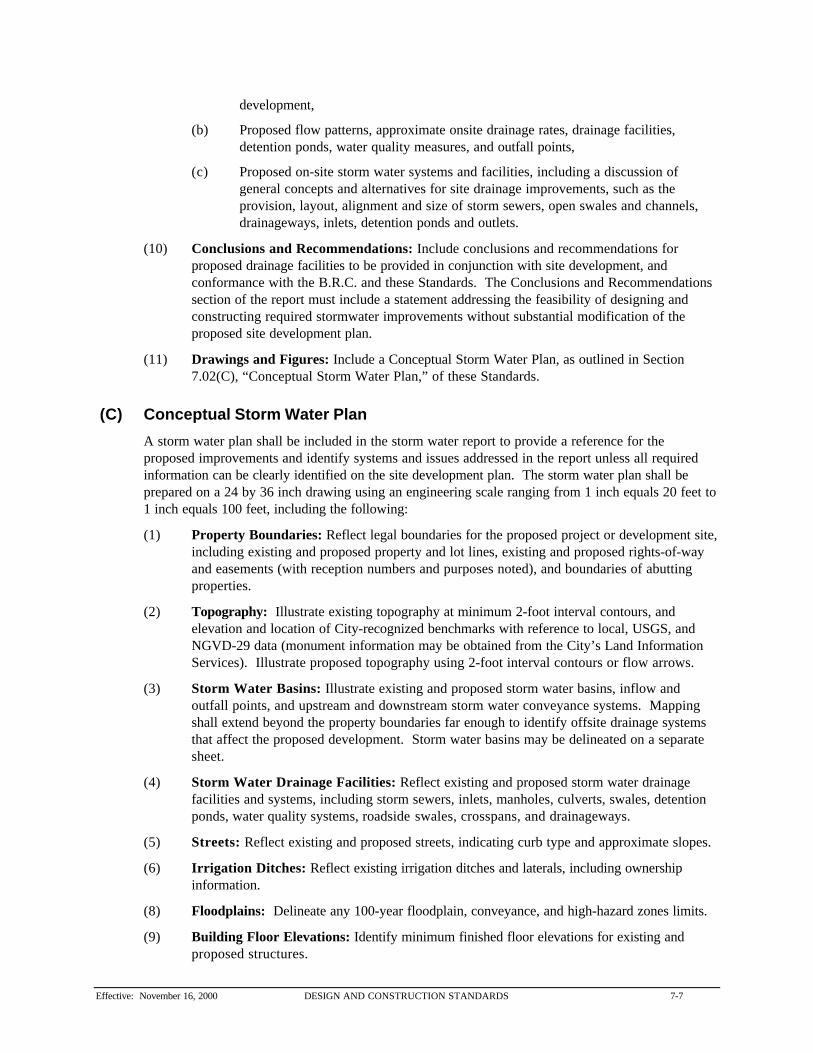
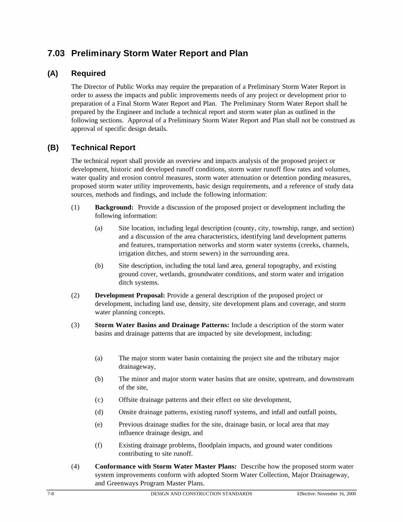


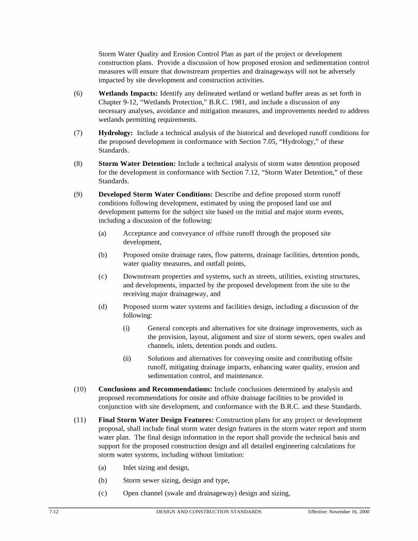
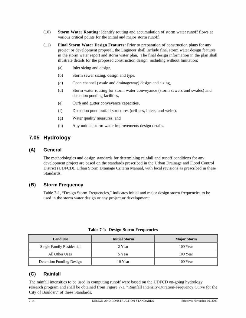


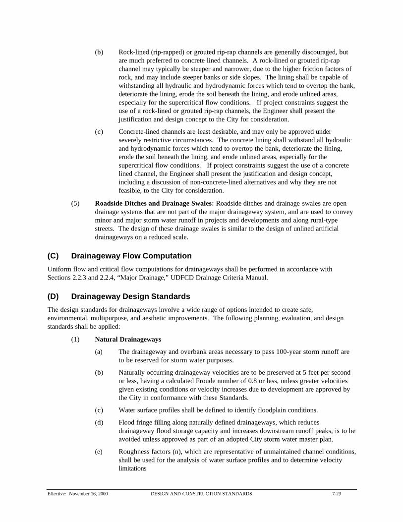


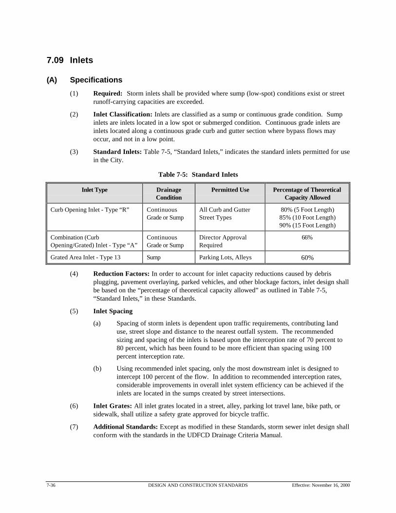
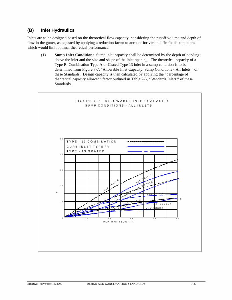


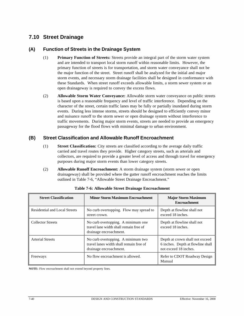


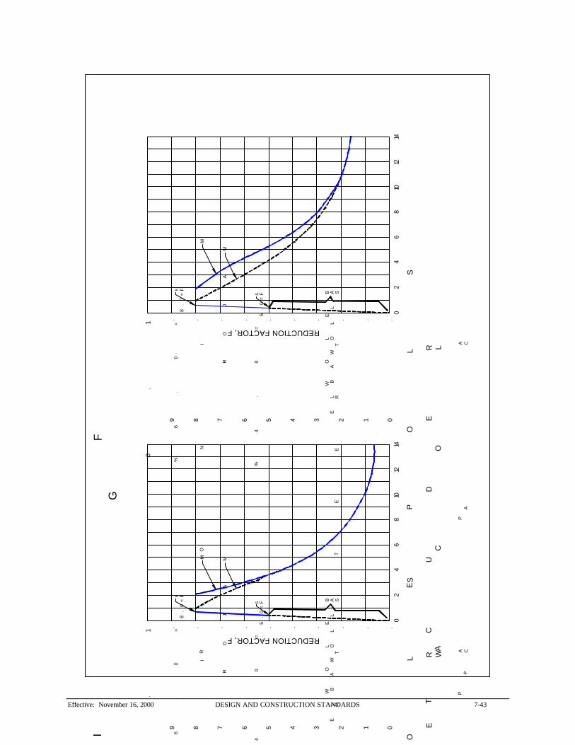

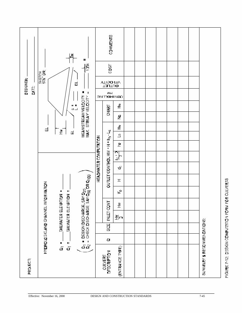


![Coupling discrete elements and micropolar continuum ...civil.colorado.edu/~regueiro/publications/...[Regueiro and Yan, 2010] that retains an “open window” compu tationally on the](https://static.documents.pub/doc/80x56/611236c163470671bf355222/coupling-discrete-elements-and-micropolar-continuum-civil-regueiropublications.jpg)

