Design and control of a brushless DC limited-angle torque motor with its application to fuel control of small-scale gas turbine engines Ching-Chih Tsai * , Shui-Chun Lin, Hsu-Chih Huang, Yu-Ming Cheng Department of Electrical Engineering, National Chung Hsing University 250, Kuo-Kuang Road, Taichung 40227, Taiwan article info Article history: Received 15 April 2006 Accepted 7 July 2008 Keywords: Actuator Fuel control Limited-angle torque motor (LATM) PID control Small-scale gas turbine engine abstract This paper presents techniques for design and control of a brushless direct-current (DC) limited-angle torque motor (LATM) with its application to fuel control of gas turbine engines. Given the desired spec- ifications, a two-pole brushless DC LATM with a toroidally wound armature is designed using selected ferromagnetic material and rare-earth permanent magnets; its electromagnetic characteristics is then computationally found and well tuned using the finite element method (FEM) in order to ensure whether the design meets the performance specifications. To achieve the simple and inexpensive semi-closed- loop fuel control, a robust position controller (including a proportional-integral-derivative (PID) control- ler with a prefilter) is synthesized for providing the required positioning performance for the developed motor, thereby achieving an inexpensive semi-closed-loop fuel control. A closed-loop fuel controller associated with the proposed position controller and a flow meter is then proposed based on multi-loop control structure in order to achieve required linear input–output relationship. All the proposed fuel con- trol laws were implemented using a stand-alone single-chip digital signal processor (DSP). Experimental results are conducted to show the efficacy and usefulness of the developed limited-angle torque motor with its application to an experimental gas turbine fuel control test platform. Ó 2008 Elsevier Ltd. All rights reserved. 1. Introduction The limited-angle torque motor (LATM) is an electromagnetic rotary actuator which converts small electrical current into limited angular movement, producing torque through a limited rotation angle of normally much less than ±180°. In order to accommodate the requirements of various applications, several different physical structures and configurations of LATMs have been presented based on their different working principles. For examples, the torque mo- tors developed in [1–3] are all based on the same polarized reluc- tance principle, Zhang et al. [4] constructed an LATM according to the Laws’ relay principle, Krishna and Kannan [5] designed and implemented a special type of brushless DC motor called brushless DC limited-angle torque motor, and Du et al. [6] presented a novel LATM where the stator is made by two pairs of permanent magnets and the rotor is composed of the winding. Common features of such motors hinge on their small physical sizes, quick response times and high flux density permanent magnets, even rare-earth permanent magnets. These torque motors have been widely used in the areas of aerospace and space equipment, optical scanning systems and even any drive systems that require limited mechan- ical rotation, ranging from the simple ON–OFF control of servo valves to the accurate tracking control of a reference signal. The brushless DC LATM has been considered as a direct-drive and frameless actuator which is designed for any positioning sys- tems requiring limited-angle operation. The brushless DC LATM has the similar structure of a typical brushless DC motor, namely that the stator supports the armature winding and the field mag- nets are mounted on the rotor. However, this type of limited-angle torque motor is much more inexpensive because the armature windings are connected for single phase, thereby eliminating the need of using the electronic switching to carry out commutation action. Furthermore, such a motor has been shown particularly useful in both aerospace and space applications with the perfor- mance benefits of high torque/power ratio, high reliability, low cost, precise positioning and maintain free operations. There are few published materials on the design of the brush- less DC LATM, in part due to the particular nature of its design and special applications and in part because of commercial confi- dentiality. In general, the structures of the brushless DC LATMs can be classified into two categories: slotted wound armature and toroidally wound armature. Krishna and Kannan [5] compared these two types of brushless DC LATM designs, and found that although the slotted wound LATMs have higher torque constant, they are with greater magnetic friction and iron losses, and even torque ripple due to cogging; on the contrary, the toroidally wound 0957-4158/$ - see front matter Ó 2008 Elsevier Ltd. All rights reserved. doi:10.1016/j.mechatronics.2008.07.003 * Corresponding author. Tel.: +886 4 22859351; fax: +886 4 22856232. E-mail address: [email protected](C.-C. Tsai). Mechatronics 19 (2009) 29–41 Contents lists available at ScienceDirect Mechatronics journal homepage: www.elsevier.com/locate/mechatronics
This paper presents techniques for design and control of a brushless direct-current (DC) limited-angletorque motor (LATM) with its application to fuel control of gas turbine engines. Given the desired spec-ifications, a two-pole brushless DC LATM with a toroidally wound armature is designed using selectedferromagnetic material and rare-earth permanent magnets; its electromagnetic characteristics is thencomputationally found and well tuned using the finite element method (FEM) in order to ensure whetherthe design meets the performance specifications. To achieve the simple and inexpensive semi-closed-loop fuel control, a robust position controller (including a proportional-integral-derivative (PID) control-ler with a prefilter) is synthesized for providing the required positioning performance for the developedmotor, thereby achieving an inexpensive semi-closed-loop fuel control. A closed-loop fuel controllerassociated with the proposed position controller and a flow meter is then proposed based on multi-loopcontrol structure in order to achieve required linear input–output relationship. All the proposed fuel con-trol laws were implemented using a stand-alone single-chip digital signal processor (DSP). Experimentalresults are conducted to show the efficacy and usefulness of the developed limited-angle torque motorwith its application to an experimental gas turbine fuel control test platform.
� 2008 Elsevier Ltd. All rights reserved.
1. Introduction
The limited-angle torque motor (LATM) is an electromagneticrotary actuator which converts small electrical current into limitedangular movement, producing torque through a limited rotationangle of normally much less than ±180�. In order to accommodatethe requirements of various applications, several different physicalstructures and configurations of LATMs have been presented basedon their different working principles. For examples, the torque mo-tors developed in [1–3] are all based on the same polarized reluc-tance principle, Zhang et al. [4] constructed an LATM according tothe Laws’ relay principle, Krishna and Kannan [5] designed andimplemented a special type of brushless DC motor called brushlessDC limited-angle torque motor, and Du et al. [6] presented a novelLATM where the stator is made by two pairs of permanent magnetsand the rotor is composed of the winding. Common features ofsuch motors hinge on their small physical sizes, quick responsetimes and high flux density permanent magnets, even rare-earthpermanent magnets. These torque motors have been widely usedin the areas of aerospace and space equipment, optical scanningsystems and even any drive systems that require limited mechan-
ll rights reserved.
: +886 4 22856232.Tsai).
ical rotation, ranging from the simple ON–OFF control of servovalves to the accurate tracking control of a reference signal.
The brushless DC LATM has been considered as a direct-driveand frameless actuator which is designed for any positioning sys-tems requiring limited-angle operation. The brushless DC LATMhas the similar structure of a typical brushless DC motor, namelythat the stator supports the armature winding and the field mag-nets are mounted on the rotor. However, this type of limited-angletorque motor is much more inexpensive because the armaturewindings are connected for single phase, thereby eliminating theneed of using the electronic switching to carry out commutationaction. Furthermore, such a motor has been shown particularlyuseful in both aerospace and space applications with the perfor-mance benefits of high torque/power ratio, high reliability, lowcost, precise positioning and maintain free operations.
There are few published materials on the design of the brush-less DC LATM, in part due to the particular nature of its designand special applications and in part because of commercial confi-dentiality. In general, the structures of the brushless DC LATMscan be classified into two categories: slotted wound armatureand toroidally wound armature. Krishna and Kannan [5] comparedthese two types of brushless DC LATM designs, and found thatalthough the slotted wound LATMs have higher torque constant,they are with greater magnetic friction and iron losses, and eventorque ripple due to cogging; on the contrary, the toroidally wound
30 C.-C. Tsai et al. / Mechatronics 19 (2009) 29–41
LATMs do not have the cogging problem because of constant reluc-tance path and relatively large air gap, and they were selected forthe specific space applications. Furthermore, the authors in [5] pro-posed two-pole and four-pole toroidally wound brushless DC LAT-Ms with the rotors made by samarium cobalt magnets (Sm2CO5);they concluded that the toroidally wound armature along withrare-earth permanent magnet rotor seems to be a good solutionfor high-performance limited rotation applications.
For the brushless DC LATM design issues in the aircraft’s andspacecraft’s applications, the selection of the permanent magnetsis another significant problem. Rao [7] discussed with the Alnicoalloy and expounded its applications. Tufts [8] offered the way toselect appropriate and adequate permanent magnets, Mhango [9]presented the reports about the benefits of new rare-earth mag-nets for aircraft applications, and Petrie [10] provided a broad over-view of permanent magnet materials with their significantadvantages and disadvantages. For example, in comparison withsamarium cobalt magnets, Neodymium–ferrite–boron magnetshave the advantages of greater peak torque capability, higher en-ergy product, higher coercive force, more compactness, and lowerenergy cost, but posses the disadvantages of bad performancevarying with temperatures and lower service temperature. Fur-thermore, Pal [11] presented comparative study of the designand development of direct drive brushed and brushless DC motorswith samarium cobalt, neodymium–iron–boron and ceramic mag-nets, Oman [12] discussed the design considerations for permanentmagnet motors and Jabbar et al. [13] investigated permanent mag-net motors for brushless operation. Yoon [14] considered stator de-sign of a brushless DC motor for robust rotor position detection ininductive sense start-up. Zheng et al. [15] presented the design andimplementation of a super high-speed cryogenic permanent mag-net synchronous motor; this kind of motor has a similar configura-tion of the brushless DC LATM. Komori and Yamane [16] developeda millimeter-sized cylindrical rotor that makes a very quick re-sponse because of its small mass (95 mg). In addition, the use ofthe finite element method (FEM), called ANSYS, has been shown ef-fort-saving and effective in designing the brushless DC LATMs in[5]. Other finite element methods for motors design have also beenreported in [17,18].
Moreover, the recent rapid and revolutionary advent of powerelectronics and microelectronics has already made digital motorcontrollers possible to implement and apply well-developedsophisticated control theories. Up to now, digital signal processors(DSPs) have been used to most applications in [19,20]. Brown et al.[21] proposed the design of the DSP subsystem for gas turbine en-gine. Due to the powerful computation abilities and high samplingrate, DSPs are much easier to perform the desired function andcontrol algorithms in real time than the conventional microcom-puters and analog controllers. With the advantages, digital signalprocessors with military specifications have become prevalent innumerous aerospace and space applications.
Although the brushless DC LATMs are not new for practitionersand engineers in the fields of aerospace and space applications, thisarticle attempts to revisit the design of the toroidally woundbrushless DC LATM with the rotor made by specific rare-earth per-manent magnets, neodymium–ferrite–boron (NdFeB), and developsimple but robust position controllers using digital signal process-ing technology, thereby resulting in more compact, powerful andreliable motors and their position controllers. The proposed motoralong with the digital controllers will be then demonstrated bymeans of its application to a fuel control system in a small-scalegas turbine engine. Small-scale gas turbine engines have becomeincreasingly important for specific aircrafts and miniature rotor-crafts, such as unmanned airborne aircraft, missiles, miniaturehelicopters and power generators [22,23]. The fuel control systemsfor such small-scale gas turbine engines are considered as key
components because they significantly affect the performanceand reliability of the small-scale gas turbine engines. Generallyspeaking, such a fuel control system is typically equipped with alow-cost but very reliable brushless DC LATM, a fuel controllerand a simple valve with associated components. The proposedbrushless DC limited-angle torque motor along with the robustDSP-based controllers will be shown useful in such a small-scaleaviation subsystem due to its quick response, accurate positioningand robustness against possible parameter variations and exoge-nous disturbances.
The main contributions of the paper are threefold: (i) a newbrushless DC LATM with required design specifications is success-fully developed utilizing the analytical approach and the finite ele-ment method, called Flux2D. Furthermore, the developed motor isproven satisfactory and consistent through experimental data. Un-like the armature winding design in [5], the gaps between any twoserial windings are especially designed in order to generate the re-quired constant output torque within the operation range of themotor. (ii) The single-chip DSP-based robust position controller issuccessfully designed and implemented to achieve semi-closed-loop fuel control in a small-scale gas turbine engine fuel control testplatform. (iii) With a flowmeter, the overall closed-loop fuel controlsystem is constructed to carry out the required linear relationshipbetween the steady-state controlled flow rates and the correspond-ing commands. The proposed motor design and control methodsare expected to be efficient and pragmatic for other aerospaceand space applications requiring aforementioned advantages.
The remainder of this paper is organized as follows. Section 2 isdedicated to the design and implementation of the brushless DCLATM utilizing the analytical approach and the finite elementmethod (FEM)-based CAD program; particular attention is paidto the performance evaluation of the proposed motor with an ana-log proportional controller. In Section 3, the small-scale gas turbinefuel control system is briefly described and the low-cost, robustsemi-closed-loop fuel controller is designed using the two-de-gree-of-freedom control structure. To eliminate the nonlinearitycaused by the fuel valve, the closed-loop fuel controller with aflowmeter is also synthesized. In Section 4, experimental resultsare conducted to verify the efficacy and usefulness of the proposedsmall-scale gas turbine fuel control system. Section 5 concludes thepaper.
2. Brushless DC LATM design and performance evaluation
This section is concerned with the techniques for design andimplementation of the brushless DC LATM. The type of torque mo-tor is specially designed for the small-scale gas turbine fuel controlmodules with performance benefits of direct drive, high reliability,high torque, accurate positioning and maintenance free operation.The high reliability comes from its simple and rugged structure,which uses a two-pole permanent-magnet rotor and a solid-corestator with a toroidally wound armature. The high torque resultsfrom the use of rare-earth permanent magnets and numerous con-ductors over one pole. The accurate position capability can be eas-ily achieved using the proposed robust position controller togetherwith the high-resolution potentiometer mounted on the rotorshaft. The maintenance free operation is due to no commutationbrushes and no switching circuitry.
2.1. Specifications
The drive motor for this application should meet the specifica-tions throughout the life time of the small-scale gas turbine fuelcontrol modules. Moreover, the motor’s output torque should re-main constant, namely that the output torque is independent of
C.-C. Tsai et al. / Mechatronics 19 (2009) 29–41 31
the rotor’s position or velocity. To achieve desired performance re-quired in the small-scale gas turbine fuel system, the brushlessDCLATM must satisfy the following specifications: (1) the physicalsize is as small as possible; (2) the maximum torque is not lessthan 1.3 kg cm; (3) the limited angular rotation or the constant tor-que region (>80% of the peak torque) is limited to ±60�; (4) the in-put voltage ranges from 0V DC to 12 V DC; (5) the maximumarmature current is 800 mA; (6)the bandwidth requirement forclosed-loop position control is greater than 5 Hz; (7) the weightof the motor is less than 600 g.
2.2. Physical configuration
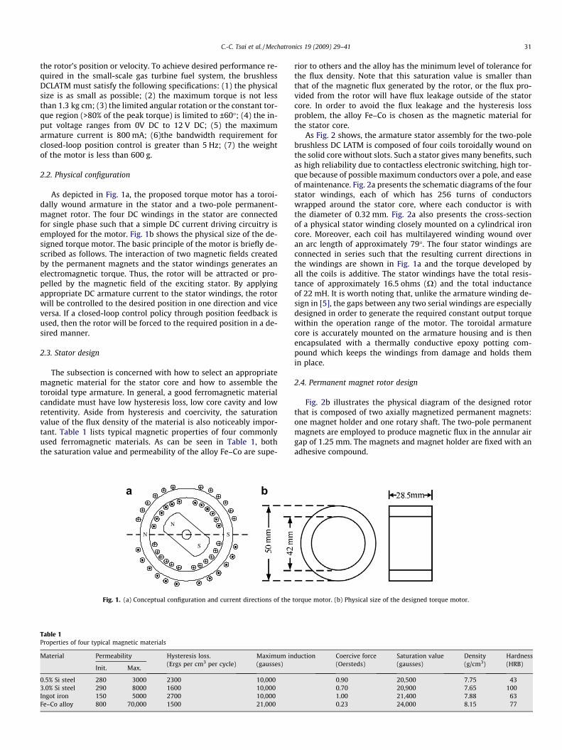
As depicted in Fig. 1a, the proposed torque motor has a toroi-dally wound armature in the stator and a two-pole permanent-magnet rotor. The four DC windings in the stator are connectedfor single phase such that a simple DC current driving circuitry isemployed for the motor. Fig. 1b shows the physical size of the de-signed torque motor. The basic principle of the motor is briefly de-scribed as follows. The interaction of two magnetic fields createdby the permanent magnets and the stator windings generates anelectromagnetic torque. Thus, the rotor will be attracted or pro-pelled by the magnetic field of the exciting stator. By applyingappropriate DC armature current to the stator windings, the rotorwill be controlled to the desired position in one direction and viceversa. If a closed-loop control policy through position feedback isused, then the rotor will be forced to the required position in a de-sired manner.
2.3. Stator design
The subsection is concerned with how to select an appropriatemagnetic material for the stator core and how to assemble thetoroidal type armature. In general, a good ferromagnetic materialcandidate must have low hysteresis loss, low core cavity and lowretentivity. Aside from hysteresis and coercivity, the saturationvalue of the flux density of the material is also noticeably impor-tant. Table 1 lists typical magnetic properties of four commonlyused ferromagnetic materials. As can be seen in Table 1, boththe saturation value and permeability of the alloy Fe–Co are supe-
N S
N
S
a b
Fig. 1. (a) Conceptual configuration and current directions of the
Table 1Properties of four typical magnetic materials
Material Permeability Hysteresis loss.(Ergs per cm3 per cycle)
Maximum in(gausses)
Init. Max.
0.5% Si steel 280 3000 2300 10,0003.0% Si steel 290 8000 1600 10,000Ingot iron 150 5000 2700 10,000Fe–Co alloy 800 70,000 1500 21,000
rior to others and the alloy has the minimum level of tolerance forthe flux density. Note that this saturation value is smaller thanthat of the magnetic flux generated by the rotor, or the flux pro-vided from the rotor will have flux leakage outside of the statorcore. In order to avoid the flux leakage and the hysteresis lossproblem, the alloy Fe–Co is chosen as the magnetic material forthe stator core.
As Fig. 2 shows, the armature stator assembly for the two-polebrushless DC LATM is composed of four coils toroidally wound onthe solid core without slots. Such a stator gives many benefits, suchas high reliability due to contactless electronic switching, high tor-que because of possible maximum conductors over a pole, and easeof maintenance. Fig. 2a presents the schematic diagrams of the fourstator windings, each of which has 256 turns of conductorswrapped around the stator core, where each conductor is withthe diameter of 0.32 mm. Fig. 2a also presents the cross-sectionof a physical stator winding closely mounted on a cylindrical ironcore. Moreover, each coil has multilayered winding wound overan arc length of approximately 79�. The four stator windings areconnected in series such that the resulting current directions inthe windings are shown in Fig. 1a and the torque developed byall the coils is additive. The stator windings have the total resis-tance of approximately 16.5 ohms (X) and the total inductanceof 22 mH. It is worth noting that, unlike the armature winding de-sign in [5], the gaps between any two serial windings are especiallydesigned in order to generate the required constant output torquewithin the operation range of the motor. The toroidal armaturecore is accurately mounted on the armature housing and is thenencapsulated with a thermally conductive epoxy potting com-pound which keeps the windings from damage and holds themin place.
2.4. Permanent magnet rotor design
Fig. 2b illustrates the physical diagram of the designed rotorthat is composed of two axially magnetized permanent magnets:one magnet holder and one rotary shaft. The two-pole permanentmagnets are employed to produce magnetic flux in the annular airgap of 1.25 mm. The magnets and magnet holder are fixed with anadhesive compound.
torque motor. (b) Physical size of the designed torque motor.
Fig. 2. (a) Schematic diagram of the toroidally wound stator assembly. (b) Physical size of the permanent magnet rotor assembly.
32 C.-C. Tsai et al. / Mechatronics 19 (2009) 29–41
2.4.1. Selection of permanent magnetsBefore selecting permanent magnets for the rotor, the under-
standing of the properties of the most useful permanent magnetsis a must. Among the most useful permanent magnets are hard fer-rite, alnico, samarium cobalt (SmCo) and neodymium–ferrite–bor-on (NdFeB). Table 2 compares the aforementioned permanentmagnets in terms of physical and magnetic characteristics, inwhich Br represents the residual flux (unit: T), Hc the coercivityforce (unit: kA/m), and BHmax the maximum of the product of themagnetic flux and magnetic intensity (unit: kJ/m3). For the temper-ature adaptability and the need of high peak torque capability,both samarium cobalt and neodymium–ferrite–boron (NdFeB)magnets are two good candidates for the rotor designed over thetemperature range from �15 �C to 80 �C. Furthermore, NdFeB per-manent magnets give the significant advantages of greater peaktorque, higher energy product, higher coercive force, allowing lar-ger air gap, less weight, less physical size and less energy costwhile compared to samarium cobalt magnets. Hence, NdFeB per-manent magnets are the chosen magnets for the rotor. Worthy ofmention is that particular protective coating is used to overcomewith the impressionable corrosion problem of NdFeB permanentmagnets through the life time of the motor.
Table 2Comparisons of the four commercial permanent magnets in terms of physical and magneticand magnetic intensity (unit: kJ/m3)
2.4.2. Air-gap magnetic flux density generated by the rotorEach pole surface of the rotor has an arc length of approxi-
mately 60� especially fitted to the requirement of the limited angu-lar movement of ±60�. From the Ampere’s law around the flux path,one obtainsI
H*
d~l ¼ Hmlm þ Hglg ¼ 0 ð1Þ
where Hm and lm represent, respectively, the magnetic intensity andthe length of the magnetic path in the stator core, and Hg and lg de-note, respectively, the magnetic intensity and the length of themagnetic path in the air gap. By assuming that no magnetic satura-tion occurs, the linear B–H characteristics of the permanent magnetmaterials are given by
Bm ¼ Br þ l0lrHm ð2Þ
where Bm and Br are the magnetic flux density in the stator and theresidual magnetic flux density in the air gap; l0 and lr are the rel-ative permeability in the free space and in the stator core, respec-tively. The continuity property of the magnetic flux U yields
U ¼ BmAm ¼ BgAg ð3Þ
properties where BHmax represents the maximum of the product of the magnetic flux
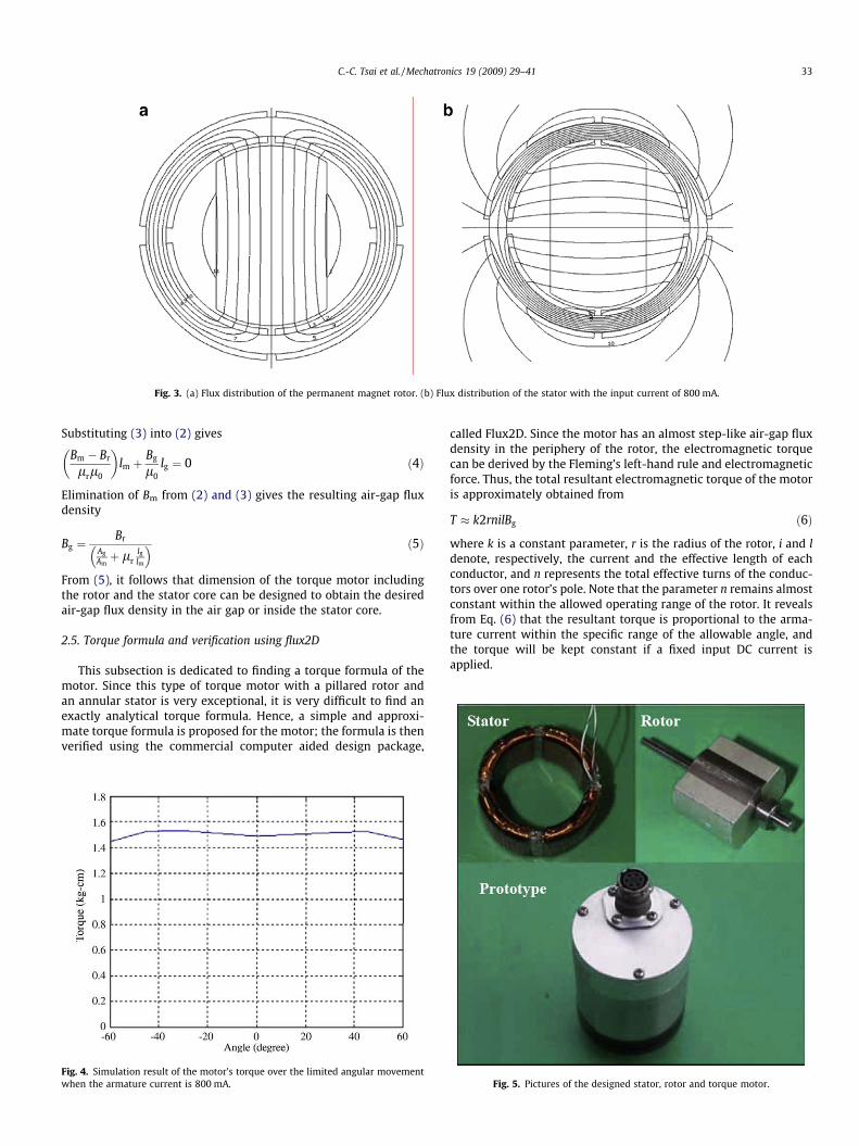
Fig. 3. (a) Flux distribution of the permanent magnet rotor. (b) Flux distribution of the stator with the input current of 800 mA.
C.-C. Tsai et al. / Mechatronics 19 (2009) 29–41 33
Substituting (3) into (2) gives
Bm � Br
lrl0
� �lm þ
Bg
l0lg ¼ 0 ð4Þ
Elimination of Bm from (2) and (3) gives the resulting air-gap fluxdensity
Bg ¼Br
AgAmþ lr
lglm
� � ð5Þ
From (5), it follows that dimension of the torque motor includingthe rotor and the stator core can be designed to obtain the desiredair-gap flux density in the air gap or inside the stator core.
2.5. Torque formula and verification using flux2D
This subsection is dedicated to finding a torque formula of themotor. Since this type of torque motor with a pillared rotor andan annular stator is very exceptional, it is very difficult to find anexactly analytical torque formula. Hence, a simple and approxi-mate torque formula is proposed for the motor; the formula is thenverified using the commercial computer aided design package,
Fig. 4. Simulation result of the motor’s torque over the limited angular movementwhen the armature current is 800 mA.
called Flux2D. Since the motor has an almost step-like air-gap fluxdensity in the periphery of the rotor, the electromagnetic torquecan be derived by the Fleming’s left-hand rule and electromagneticforce. Thus, the total resultant electromagnetic torque of the motoris approximately obtained from
T � k2rnilBg ð6Þ
where k is a constant parameter, r is the radius of the rotor, i and ldenote, respectively, the current and the effective length of eachconductor, and n represents the total effective turns of the conduc-tors over one rotor’s pole. Note that the parameter n remains almostconstant within the allowed operating range of the rotor. It revealsfrom Eq. (6) that the resultant torque is proportional to the arma-ture current within the specific range of the allowable angle, andthe torque will be kept constant if a fixed input DC current isapplied.
Fig. 5. Pictures of the designed stator, rotor and torque motor.
Fig. 7. Step response of the built motor using analog proportional position control.
34 C.-C. Tsai et al. / Mechatronics 19 (2009) 29–41
For verifying the validity of the torque formula (6), a powerfulmagnetic circuit analysis tool, called Flux2D, is used to proceedwith computational torque analysis and the design refinementfor the motor. Using the standard procedure to input the geometry,physical property and input current of the motor, one can simulatethe torque and the magnetic flux density generated respective bythe stator’s windings and the rotor via the finite element methodin the package Flux2D. Fig. 3, respectively, depicts the resultantflux distributions of the permanent magnet rotor and the statorwhen the rotor is at the position in Fig. 3a. The results in Fig. 3aand b indicate that two magnetic fields caused by the rotor andthe stator are almost perpendicular, thus generating required elec-tromagnetic torque. The result in Fig. 4 reveals that given the max-imum input current, the simulated torque remains approximatelyconstant at the entire constrained rotor’s angles.
2.6. Performance evaluation
Fig. 5 presents the prototype of the constructed motor with thestator core made by the alloy Fe–Co and the rotor with NdFeB per-manent magnets. Two experiments were conducted to examinethe performance of the motor; one was performed by setting thearmature current to be 800 mA and altering the rotor’s angles,and the other was carried out by changing the armature currentbut keeping the rotor at a fixed constant angle, for example, 40�.Fig. 6 depicts the experimental torque of the designed motor overthe limited rotor’s angles and the relationship of torque and the
Fig. 6. (a) Experimental motor torque over the limited rotor’s angles when thearmature current is 800 mA. (b) Plot of torque versus armature current for thedesigned motor.
armature current. The minimum and maximum torque outputsof the motor are about 1.37 kg cm and 1.43 kg cm, respectively.In Fig. 6, although the experimental torque outputs are less thanthe simulated ones, the experimental result showed a high degreeof consistence with the predicted one. Fig. 6a also shows that whenthe armature current is 800 mA, the total resultant electromag-netic torque of the motor is approximately obtained from Eq. (6),and the torque remains almost constant within the limited rotor’sangles from �60� to 60�. This result clearly confirms the validity ofthe torque equation (6). Moreover, the result in Fig. 6b shows thatthe approximate torque equation (6) is correct and useful, namelythat the torque equation (6) is shown valid, the generated torque isproportional to the armature current, and independent of the ro-tor’s positions. Worthy of mention is that although the result inFig. 6b was obtained from the second experiment, it can be furtherverified by conducting the same experiment with different rotor’sangles.
To further investigate the dynamic behavior of the proposedmotor, Fig. 7 depicts the step-like set-point transient response ofthe designed motor using an analog proportional position control-ler with its proportional gain of 0.3. The unit step input means theinput reference of 1 VDC, and the transient response represents thetime behavior of actual position of the controlled motor. In controlterminology, such a transient response can be used to find a dy-namic model of the motor. Furthermore, the result in Fig. 7 revealsthat the analog P controller with gain 0.3 was poor for obtainingsatisfactory closed-loop transient response because the closed-loop positioning response had a significant maximum overshotand long settling time. Nevertheless, the experimental responsewith respect to the kind of input reference will be employed toestablish an approximate transfer function of the motor.
In the sequel a two-degree-of-freedom position controller willbe synthesized in the following section to improve the bad dy-namic response of the torque motor while applied to small-scalegas turbine engine fuel control.
3. Application to fuel control of a small-scale gas turbine engine
3.1. Brief description of the small-scale gas turbine fuel system
This subsection aims to briefly describe the fuel control systemof a small-scale gas turbine engine where the fuel flow rate is theultimate controlled variable. Fig. 8 shows the physical configura-tion of a typical fuel control system in a small-scale gas turbine en-gine, where the controlled fuel flow rate at the outlet of the system
Fig. 8. Physical configuration of a typical small-scale gas turbine fuel system.
C.-C. Tsai et al. / Mechatronics 19 (2009) 29–41 35
directly affects the propulsion power of the small-scale gas turbineengine. The torque motor is directly connected to the variable-throttle valve where the opening degree (area) of the orifice con-trols the fuel flow rate into the small-scale gas turbine engine.The pressure control valve is employed to ensure that the differen-tial hydraulic pressure between the inlet and the outlet of the var-iable-throttle valve is constant. The safe valve is a protectiondevice to prevent the pressure from dangerous level tolerance.The loop control module makes sure that fuel flows to the spraynozzle at a specified direction. In the following, the nonlinear prop-erties of the pressure control valve and the variable-throttle valvewill be briefly introduced. The pressure control valve is used tomaintain the differential pressure between the inlet and outlet ofthe variable-throttle valve. Thus, the flow rate Q of the fuel valveis described by
where Cd is the orifice discharge coefficient, q is the density of thefuel, Pi represents the inlet pressure, Po the outlet pressure, and Dpis the differential pressure between the inlet and outlet. Assumingthat Dp be kept constant due to the pressure control valve, thenthe flow rate depends on the open area A(h). The variable-throttlevalve is directly mounted on the torque motor. The open area A ofthe orifice on the valve is the function, A(h), of the rotary angle hof the torque motor. Notice that the function A(h) depends uponthe shape of the valve. Fig. 9 shows the nonlinear relationship be-
Valve te
0
100
200
300
400
500
600
700
800
900
1000
0.00Percenta
Flow
rat
e (P
PH
)
Flow rate (PPH)
ip
50.0040.0030.0020.0010.00
Fig. 9. Flow rate characteristics o
tween the flow rate and the opening percentage (area) of the valve,where the differential pressure Dp is made constant via the pres-sure control valve. Note that a constant load torque about 0.8 kg cmwas applied to the valve during experimentation and this torqueprofile was provided using a small dynamometer. The result inFig. 9 also indicates the static or steady-state relationship betweenthe flow rate and the opening percentage of the valve.
3.2. Fuel controllers design
The main design idea of the overall fuel controller is to achieveconsistent performance of the fuel control system in spite ofparameter variations occurring in the proposed LATM and exoge-nous disturbances. In this subsection, a multi-loop control schemeis employed to accomplish such a control goal by introducing aninner loop, called robust position control loop, to overcome theparameter variations, and an outer loop to carry out the flow ratecontrol with desired performance without any steady-state track-ing errors. The inner loop is composed of a feedforward controller(prefilter) and a PID controller, aiming at obtaining robustly andconsistently transient responses of the motor in the presence ofuncertainties and disturbances. The outer loop, consisting of a sim-ple PI controller and a flow meter, is used to obtain an almost lin-ear relation between the flow rate commands and actual flowrates. It is worth mentioning that if the inner loop is employedwithout the outer loop, then the fuel control system still worksbut gives an imperfect linear input–output relationship; however,this kind of semi-closed-loop fuel control policy provides an
st
ge (%)
0
50
100
150
200
250
300
Pres
sure
(PS
IG)
i op p -p=
op
100.0090.0080.0070.0060.00
Δ
f the variable throttle valve.
Fig. 10. Block diagram of the proposed semi-closed-loop fuel control system.
+15V
+15V
-15V
-15V
TLO81CP2Q
1D
2DActuator
FeedbackV
R
cV
OPA
-TL
1Q
a
b
Fig. 11. (a) The proposed driving circuit. (b) The static voltage-to-currentrelationship.
36 C.-C. Tsai et al. / Mechatronics 19 (2009) 29–41
inexpensive implementation due to no additional flow meter. Onthe other hand, for some applications which require precise fuelcontrol, then the closed-loop PI fuel controller associated withthe cascaded position control structure and a flow meter is thenproposed to accomplish almost linear input–output relationship.However, this closed-loop fuel controller is designed at the costof an expansive flow meter.
3.3. Semi-closed-loop fuel control
Fig. 10 depicts the block diagram of the semi-closed-loop fuelcontrol system for the small-scale gas turbine engine, in whichthe inner control loop (robust position control loop for the motor)is employed without consideration of flow dynamics and nonlinearcharacteristics of the variable throttle valve. The use of the robustmotor position control system is necessary to provide the requiredpositioning performance for the developed motor, thereby achiev-ing the simple and inexpensive fuel control. Although giving thenonlinear steady-state relationship between the fuel flow ratesand the fuel input commands (see Fig. 18), this simple fuel control-ler can be applicable to some kinds of small-scale gas turbine en-gines that requires low-cost fuel control system. In theseapplications where only the inner control is needed, the prefilterhas to be introduced in order to cancel out the system zero(s) suchthat the resultant LATM position controller is capable of obtainingdesired robust set-point tracking performance for the motor.
3.3.1. DSP-based LATM position control systemThe DSP-based position control system for the proposed LATM
is shown in Fig. 10, where the main controlled variable is the shaftposition h of the torque motor. The potentiometer transforms theshaft position into the voltage used for feedback for the controller.Thus, the negative feedback path constitutes a closed loop for thecontrol system. The single-chip DSP (TMS320F240) from TexasInstruments is responsible for executing all the synthesized controlactions; accordingly, the controller has to continuously monitorthe feedback voltages from the potentiometer as well as the inputposition commands. Furthermore, the controller uses the digital-to-analog converter to convert the parallel 8-bit digital signals intothe corresponding analog control voltage, and the control voltage islinearly transformed into the driving current for the torque motorby the driving circuitry.
3.3.2. Motor driving circuitryThe type of motor driving circuit is a current-boosted voltage-
to-current circuit as shown in Fig. 11a. This circuitry uses the neg-ative feedback principle to achieve an almost linear voltage-to-cur-rent relationship. The main function of two power transistors, Q1
and Q2, is to amplify the output current to the torque motor suchthat the motor is controlled in the current mode. Fig. 11b displaysthe experimental result of the static voltage-to-current relation-ship. The result in Fig. 11b presents that the driving module is lin-ear except the saturation regions.
3.3.3. Experimental modeling of the torque motorThis subsection is devoted to finding an approximate transfer
function of the torque motor from experimental data. As can be
C.-C. Tsai et al. / Mechatronics 19 (2009) 29–41 37
seen in Fig. 7, the dynamic behavior of the simple feedback controlsystem with analog proportional position control indeed exhibitedan approximately second-order system response, which can bemodeled by following second-order transfer function
TðsÞ ¼ x2n
s2 þ 2nxnsþx2n; 0 < n < 1 and xn > 0 ð8Þ
By using the experimental data from the step response from Fig. 7,the damping ratio n and the natural frequency xn are obtained frommeasurements of the maximum overshot and the settling time, thatis,
Mp ¼ e�pn=ffiffiffiffiffiffiffiffi1�n2p
ð9Þ
tr ¼p� tan�1
ffiffiffiffiffiffiffiffi1�n2p
n
xn
ffiffiffiffiffiffiffiffiffiffiffiffiffiffi1� n2
p ð10Þ
As Fig. 9 shows, the maximum overshoot Mp is 0.64 and the risingtime tr is 21.8 ms and the proportional gain, KP, of the analog con-troller is 0.3. With the data, the closed-loop transfer function canbe then found by
TðsÞ ¼ KPGðsÞ1þ KPGðsÞ ¼
2043s2 þ 12:71sþ 2043
ð11Þ
which leads to the open-loop transfer function of the torque motor
GðsÞ ¼ TðsÞKpð1� TðsÞÞ ¼
20430:3ðs2 þ 12:71sÞ ¼
6810sðsþ 12:71Þ ð12Þ
3.3.4. Robust position controller designThe basic structure of the proposed robust position control sys-
tem for the LATM is shown in Fig. 12 in which R(s) represents thereference input of the closed-loop fuel control system, U(s) the out-put of the compensator Gc(s), D(s) exogenous disturbance in thecontrol system, and C(s) the output of the close-loop fuel controlsystem. The designed objective is to select a prefilter Gp(s) and acompensator Gc(s) in a two-degree-of-freedom feedback configura-tion so that the transient, and steady state, and frequency domainspecifications are satisfied. In addition, the controller design mustmeet the bandwidth requirement and to prevent the unavoidablemeasurement noise from degrading the control performance orgiving saturation at the stage of Gc(s) or at the early start-up stage.The proposed robust position control system is based on a specialtype of performance index as in (13) to select the three PID coeffi-cients [24].
ITAE ¼Z 1
0tjeðtÞjdt ð13Þ
where the performance index is designated the Integrated Timemultiplied by Absolute Error, abbreviated by ITAE. This ITAE perfor-mance index is used to reduce the contribution of the large initialerrors to the value of the performance integral, as well as to empha-size errors occurring large in the response. The ITAE performancecriterion for any step input has been employed to determine theoptimal coefficients of the following general nth-order closed-looptransfer function [24]
Fig. 12. Block diagram of the robust position control system.
TðsÞ ¼ CðsÞRðsÞ ¼
b0
sn þ bn�1sn�1 þ � � � þ b1sþ b0
which gives a zero steady-state error for a step input. For example,for the third-order closed-loop transfer function, its characteristicequation with the best coefficients determined by the ITAE criterionis s3 þ 1:75xns2 þ 2:15x2
nsþx3n ¼ 0 in which the natural frequency
xn is obtained from the specification of settling time. Next, theaforementioned technique will be applied to find the robust posi-tion controller, which is composed of a PID controller and a prefil-ter. Given the PID controller
GcðsÞ ¼Kds2 þ Kpsþ K i
sð14Þ
where Kd, Kp and Ki are the three-term parameters, the closed-looptransfer function without the prefilter T0(s) is given by
T 0ðsÞ ¼ CðsÞR0ðsÞ
¼ GcGðsÞ1þ GcGðsÞ
¼ 6810ðKds2 þ Kpsþ K iÞs3 þ ð12:71þ 6810KdÞs2 þ 6810Kpsþ 6810K i
ð15Þ
By choosing xn = 50 rad/s to meet the bandwidth requirement, oneobtains the optimum coefficients of the third-order characteristicequation for ITAE by
s3 þ 87:5s2 þ 5375sþ 125000 ¼ 0 ð16Þ
Equating the denominator of (15), (16) yields the three-termcoefficients Kp = 0.7893, Ki = 18.3554, and Kd = 0.011. To achievethe desired ITAE response, it requires that the overall transfer func-tion from the input R(s) to the output C(s) becomes
TðsÞ ¼ CðsÞRðsÞ ¼
GpGcGðsÞ1þ GcGðsÞ ¼
125000s3 þ 875s2 þ 5375sþ 125000
ð17Þ
From (17), the prefilter is obtained from
GpðsÞ ¼1671:3464
s2 þ 71:754sþ 1671:3ð18Þ
which cancels out the zero in (15) and makes the overall system be-come a unity-gain system. This completes the design of the robustposition controller for the LATM. Computer simulation results showthat the robust position controller generates small overshoots of1.9%, desired rising time of 0.04 s and settling time of 0.14 s for aunit step disturbance, and the maximum value of C(t)/D(t) due tothe disturbance is 0.08%, showing satisfactory disturbance rejectioncapability. Note that, to obtain desired transient responses for anystep-like position setpoints, the prefilter must be employed to can-cel out the two system zeros form the PID controller in the feedbackloop. If these two system zeros are not cancelled out by the prefilter,the overall position control loop will have a very oscillatory tran-sient response whose percentage of maximum overshoot can beup to 36.5%.
3.4. Closed-loop fuel controller design with a flowmeter
The design of the previous semi-closed-loop fuel control systemis easy and simple, but at the cost of the nonlinear input–outputrelationship between the fuel rate command and the actual fuelflow rate. This is in part due to the nonlinear variable-throttle va-lue, and in part because of no flow transducer for measuring thefuel flow rate. Moreover, another drawback of the previous semi-closed-loop fuel controller is that its overall set-point step trackingperformance varies with the input fuel rate commands. To over-come the shortcoming, this subsection aims at designing a feed-back controller with a flowmeter, and the control objective is tohave the linear relationship between the input fuel rate commandand the output fuel flow rate. Fig. 13 illustrates the block diagram
Fig. 13. Block diagram of the closed-loop fuel control system with a flow meter.
38 C.-C. Tsai et al. / Mechatronics 19 (2009) 29–41
of the closed-loop fuel control system with a flowmeter. As shownin Fig. 13, the transfer function Gv(s) indeed represents an approx-imation of the closed-loop transfer function of the inner positioncontrol loop and flow dynamics. To proceed with the approximatemodeling process, it is necessary to conduct several experiments toobtain transient responses of the transfer function Gv(s) for the fol-lowing four cases: (1) Vset = 0.5 V; (2) Vset = �0.5 V; (3)Vset = �1.0 V; (4) Vset = �1.5 V. Fig. 14a–d depicts the four set-pointtracking responses. From the experimental data, the transfer func-tions for the four cases are experimentally obtained as follows; (1)Gv1 ¼ 9:92
sþ5:95; (2) Gv2 ¼ 6:709sþ5:81; (3) Gv3 ¼ 5:0168
sþ5:81; (4) Gv4 ¼ 4:276sþ4:83.
Thus, the transfer function of the position control loop and flowdynamics can be given by the following first-order system model:
which has the time-varying parameters and steady-state errors forany set-point input.
Note that the response time of the used flowmeter (Model FT4-6 from FlowMeasurementSystems) is about 4 ms, thereby givingits bandwidth of 250 Hz. In comparison the bandwidth of the innerposition control loop along with flow dynamics (about 5–6 rad/s),
the dynamics of the flowmeter is much faster and can then be ne-glected in the controller design.
Since the model (19) has the time-varying parameters and stea-dy-state error for a step input, a PI control policy is employed toachieve the design goal. The transfer function of the overall systemis
TðsÞ ¼ KðKPsþ K IÞs2 þ ðaþ KKPÞsþ KK I
ð20Þ
where the natural frequency xn is designed to be smaller than18 rad/s since xn of the inner loop is 50 rad/s. This implies
KK I 6 324 ð21Þ
To complete the controller synthesis, we consider the worst casethat a = 5.95 and K = 9.92. Assume that the desired minimum-damping ratio f must be larger than 0.6, and then the selectionsof Kp and KI must satisfy the following two inequalities:
2:26 6 Ki 6 32:6
Kp P 1:2ffiffiffiffiK i
p�1:88
3:15
(ð22Þ
Hence, a simple PI fuel controller with the flowmeter is chosen as
Gf ðsÞ ¼ 2þ 15s
ð23Þ
4. Fuel control experiments, results and discussion
4.1. Experimental setup
Fig. 15 depicts the control architecture of the experimentalsmall-scale gas turbine fuel control system and the prototype of
Fig. 15. Monitoring and control architecture of the experimental small-scale gas turbine engine fuel controller.
C.-C. Tsai et al. / Mechatronics 19 (2009) 29–41 39
the DSP-based fuel control board. The robust position controllerdeveloped in Section 3.3.4 is considered as the inner loop control-ler and the closed-loop PI fuel controller is then considered as theouter loop controller. The flow rate signal measured by the flow-meter is a sinusoidal wave of low magnitude, and is amplifiedand converted to a square wave. The frequency-to-voltage con-
Fig. 16. Picture of the experim
verter (FVC) converts the frequency of the square wave into a cor-responding analog voltage. The PI fuel controller performs theclosed-loop control using the feedback voltage of the flow rate. Be-side, the remote supervisor using LabVIEW can monitor thechanges of the variable in the system or manipulate the controlledvariable through the serial port. The flow meter has a small fan and
ental fuel control system.
40 C.-C. Tsai et al. / Mechatronics 19 (2009) 29–41
several induction coils. As the fuel flows through it, the fan gener-ates a rotary movement. This action causes the coils to induce asinusoidal voltage, which is proportional to the flow rate of thefuel. Fig. 16 depicts the experimental fuel system.
Fig. 17. (a) Unit step response of the controlled torque motor. (b) Unit stepresponse of the controlled torque motor in the presence of external disturbance.
Fig. 18. Comparison of the steady-state flow rate characteristics of the p
4.2. Semi-closed-loop fuel control experiments
The experiment was conducted to examine and verify theproposed DSP-based robust position controller for achievingsemi-closed-Loop fuel control. Fig. 17a depicts the set-point track-ing response of the proposed robust position controller whose per-formance is characterized by the maximum overshoot of 0%, therising time of 0.04 s, and the settling time of 0.12 ms. The resultclearly indicate that the experimental result is highly consistentwith the simulation result in Section 3.3.4. Furthermore, addingan extra load torque 0.8 kg cm to the shaft obtained the experi-mental set-point tracking response, as shown in Fig. 17b. The resultin Fig. 17b also reveals that the robust position controller has theexcellent disturbance rejection as predicted by the previousnumerical simulation. Fig. 18 shows that the kind of fuel controllergives the nonlinear steady-state relationship between the fuel flowrates and the fuel input commands. Notice that the saturation ofthe fuel control system is unavoidable due to the characteristicsof the variable-throttle valve.
4.3. Experimental results of the closed-loop fuel controller with theflowmeter
Fig. 19 shows the transient step response of the fuel controllergiven in (23) for the worst case. Worthy of mention is that there
roposed semi-closed-loop controller and closed-loop fuel controller.
Fig. 19. Experimental closed-loop response of the controlled torque motor with theSetpoint Vref = 1 V.
C.-C. Tsai et al. / Mechatronics 19 (2009) 29–41 41
are no steady-state errors in Fig. 19. This shows that the perfor-mance of the proposed fuel controller with the flowmeter is greatlyimproved while compared with the semi-closed-loop fuel control-ler. Fig. 18 compares the steady-state fuel flow characteristics ofthe two proposed fuel controllers. The results in Fig. 18 indicatethat the nonlinearity caused by the semi-closed-loop fuel control-ler is almost eliminated via the closed-loop feedback policy.
5. Conclusions
This paper has proposed techniques for design and implementa-tion of a brushless DC limited angle torque motor with its applica-tion to fuel control of small-scale gas turbine engines. ThroughFEM-based computer simulations and experimental results, thedesign strategy of the proposed brushless DC LATM has been con-firmed effective and useful in achieving required specifications.The two-degree-of-freedom position controller has been success-fully designed and implemented on a DSP chip for the LATM. Withthe robust position controller, the semi-closed-loop fuel controlleris easily developed to accomplish a low-cost fuel supply strategyfor small-scale gas turbine engines, but its relationship betweenthe steady-state fuel flow rates and their commands remains non-linear. Therefore, the closed-loop fuel controller with a flow meteris then synthesized to accomplish desired linear relationship. Theexperimental results have shown that the closed-loop fuel controllerovercomes the plant uncertainties and nonlinearity. In comparisonwith both proposed fuel control approaches, the semi-closed-loopfuel controller is much more inexpensive than the closed-loop fuelcontroller, but the latter outperforms the former in terms of tran-sient responses and steady-state characteristics. An interesting to-pic for future research might be to design a linear throttle valve soas to greatly reduce the design complexity and cost of the fuelcontroller.
Acknowledgements
The authors acknowledge financial support in part from the Na-tional Science Council of the Republic of China under Grant NSC89-CS-D-005-001, and in part from the Ministry of Education,Taiwan, under the ATU plan.
References
[1] Dawson C, Bolton HR. Performance prediction of a wide-angle limited-motionrotary actuator. Proc Inst Elect Eng, Part B 1978;125(9):895–8.
[2] Dawson C, Bolton HR. Design of a class of wide-angle limited-motion rotaryactuators. Proc Inst Elect Eng Part B 1979;126(4):345–50.
[3] Dawson C, Bolton HR. Limited-motion rotary actuators of toroidal-stator,permanent-magnet rotor type. Proc Inst Elect Eng, Part B 1982;129(4):190–8.
[4] Zhang Y, Smith IR, Kettleborough JG. Performance evaluation for a limited-angle torque motor. IEEE/ASME Trans Mechatron 1999;4(3):335–9.
[5] Krishna PM, Kannan N. Brushless DC limited angle torque motor. In:Proceedings of the 1996 international conference on power electronics,drives and energy systems for industrial growth, vol. 1; 1996; p. 511–6.
[6] Du CY, Li T, Cao ZC. Accurate tracking control of a limited angle torque motor.In: Proceedings of the conference record of the 38th IEEE IAS annual meetingand industry applications, vol. 2; 2003. p. 744–8.
[7] Rao AS. Alnico permanent magnets and overview. In: Proceedings of theelectrical electronics insulation conference and electrical manufacturing & coilwinding conference; 1993. p. 373–83.
[8] Tufts CR. Selecting the correct magnetic material. In: Proceedings of theelectrical electronics insulation conference; 1995. p. 65–8.
[9] Mhango LMC. Benefits of Nd–Fe–B magnet in brushless DC motor design foraircraft applications. In: Proceedings of the fourth international conference onelectrical machines and drives; 1989. p. 76–9.
[10] Petrie R. Permanent magnets in review. In: Proceedings of the electricalelectronics insulation conference and electrical manufacturing & coil windingconference; 1993. p. 207–10.
[11] Pal SK. Comparative study of the design and development of direct drivebrushed and brushless DC motors with samarium cobalt, neodymium–iron–boron and ceramic magnets. IEE Colloquium on Permanent Magnet Machinesand Drives 1993:711–7.
[12] Oman H. Permanent magnets for vehicle-propulsion motors: cost/availability.In: Proceedings of the energy conversion engineering conference, vol. 1; 1996.p. 91–6.
[13] Jabbar MA, Low TS, Rahman MA. Permanent magnet motors for brushlessoperation. IEEE Trans on Ind Appl 1990;26:124–9.
[14] Yoon T. Stator design consideration of a brushless DC motor for robust rotorposition detection in inductive sense start-up. IEEE Trans Magn2006;42(3):453–9.
[16] Komori M, Yamane T. Magnetic levitation system with a millimeter-sizedcylindrical rotor. Mechatronics 2000;10:595–607.
[17] Pinhas BT, Mrad RB, Goldenberg AA. A conceptual design and FE analysis of apiezoceramic actuated dispensing system for microdrops generation inmicroarray applications. Mechatronics 2007;17:1–13.
[18] Gair S, Canova A, Eastham JF, Betzer T. A new 2D FEM analysis of a discmachine with offset rotor. In: Proceedings of the 1996 internationalconference on power electronics, drives and energy systems for industrialgrowth, vol. 1; 1996. p. 617–21.
[19] Hanselmann H. DSP in control: the total development environment. In:Proceedings of the 1996 IEEE IECON 22nd international conference onindustrial electronics, control, and instrumentation, vol. 3; 1996. p. 1647–54.
[20] Choi C, Tsao TC. Control of linear motor machine tool feed drives for endmilling: Robust MIMO approach. Mechatronics 2005;15:1207–24.
[21] Brown MN, Stewart RW, Durrani TS. DSP subsystem for knowledge basedhealth monitoring of gas turbine engines. In: Proceedings of the IEEEinternational conference on acoustics, speech, and signal processing, vol. 5;1992; p. 69–72.
[22] Exley TJ. Low cost propulsion for unmanned air vehicles. American Institute ofAeronautics and Astronautics paper 1991;29:2559.
[23] Nikkhajoei H, Iravani MR. A matrix converter based micro-turbine distributedgeneration system. IEEE Transactions on Power Delivery 2005;20(3):2182–92.
[24] Dorf RC, Bishop RH. Modern control systems. 10th ed. New York: Prentice-Hall; 2005.