D-Ri34 374 DESIGN AND D EVELOPMENT OF MILITARY PETROLEUM HOSELINE 112, SYSTEM(U) FOSTER-MILLER INC WALTHAM MR CETINER ET AL. AUG 83 MER0216-FM-8055-5 UNLASIIDRDAK708-C-02i6 F/G i3/ii H j UCRSFEEI-EEommhmiE
Transcript
D-Ri34 374 DESIGN AND D EVELOPMENT OF MILITARY PETROLEUM HOSELINE 112,SYSTEM(U) FOSTER-MILLER INC WALTHAM MR
CETINER ET AL. AUG 83 MER0216-FM-8055-5
UNLASIIDRDAK708-C-02i6 F/G i3/ii H
j UCRSFEEI-EEommhmiE
-~~9 1. L8
~- S
11111. 11112.
11111.2 1.6
MICROCOPY RESOLUTION TEST CHARTNATIONAL BUREAU OF STANDARDS- 1963-A
712
Report MER0216-FM-8055-5
DESIGN AND DEVELOPMENT OF MILITARYPETROLEUM HOSELINE SYSTEM
M. Selim CetinerJames L. FinneyF. GravesFoster-Miller, Inc.350 Second AvenueWaltham, MA 02254
August 1983
Final Report for Period October 1980 -August 1983
Fort Belvrr, VA 2206 ' .* -
"T
LJq Prepared for
SU.S. ARMY MOBILITY EQUIPMENT RESEARCH AND DEVELOPMENT COMMANDFort Belvoir, VA 22060
17 17
SECURITY CLASSIFICATION OF T04IS PAGE (When Dco Entered)
REPORT DOCUMENTATION PAGE BEFORE COMPLETING FORM
4. TITLE (and Subtilef) S. TYPE OF REPORT & PERIOD COvERED
Design and Development of Military Final ReportPetroleum Hoseline System
6. PERFORMING ORG. REPORT NUMBER
IMER 0216-FM-8055-57. AUT14OR(s) 8. CONTRACT OR GRANT NUMUER(s)
M. Selim Cetiner DAAK 70-80-C-0216James L. FinneyF. Graves______________
S. PERFORMING ORGANIZATION NAME AND ADDRESS 10. PROGRAM ELEMENT. PROJECT. TASKAREA II WORK UNIT NUMBERS
Foster-Miller, Inc.350 Second AvenueWaltham, MA 02154
ICONTROLLING OFFICE NAME AND ADDRESS 12. REPORT DATE
I3. NUMBER OF PAGES
14. MONITORING AGENCY NAME A AOORESS(iI different from Controlling Office) IS. SECURITY CLASS. (at this report)
Unclassified
ISa. DECLASSI FICATION/ DOWNGRADINGSCHEDULE
AA
III. STRPPUTMNTAYNTEETS1ti eot
19. KEY TRDT S T EEN (Cntnu threer e ebitrneessr e nerd intok.ifyb blkner) ,. eot
Petroleum hoseline Detail designHoseline reel assembly Deploy/recover procedureConcept study Lightweight collapsible hose( 5-ton military truck Purge and evacuation
20. ABSTRACT (Continue on revere side If necessay end Identify by block number)
2;7The objective of this program has been to develop: a) a self-containedHoseline Reel Assembly for deploying and picking up 6 inch lightweight,
collapsible petroleum hoseline in a tactical situation, and b) a 6 inchdiameter lightweight collapsible hoseline. This final report describesthe development of the hoseline and the hoseline reel assembly.
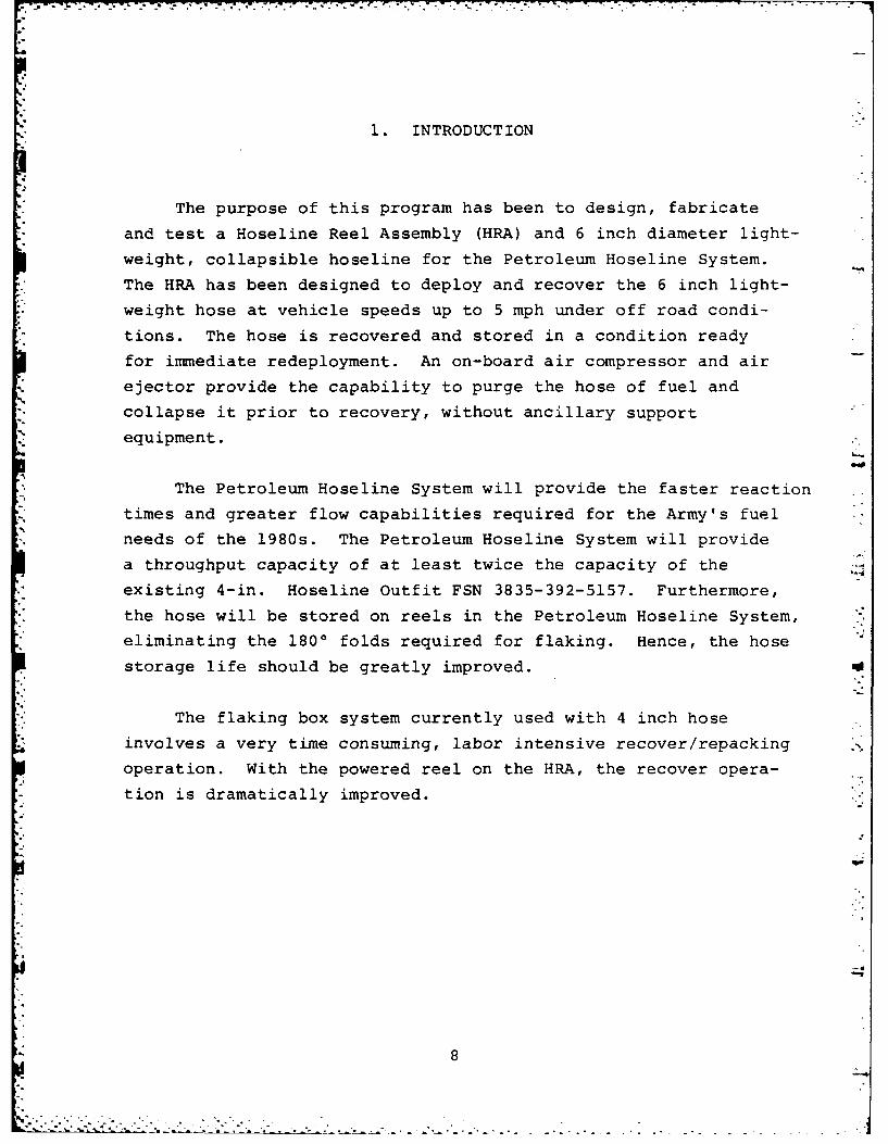
Paragraph 1 INTRODUCTION ....... .............. 12 ENGINEERING DEVELOPMENT GOALS FOR
THE PETROLEUM HOSELINE SYSTEM . ... 93 CONCEPT DEVELOPMENT AND EVALUATION. . . 133.1 Hose reel density study ......... . 133.1.1 Reel volume calculation study. ... 133.1.2 Reel hub study ........ ..... 183.1.3 Experimental hose analysis ..... . 213.2 Operational procedure analysis . . . 243.3 Fundamental arrangement study. ... 293.4 The first design review. ....... 463.5 Resolution of the final concept. 494 SUBSYSTEM CONFIGURATIONS FOR THE
PETROLEUM HOSELINE SYSTEM ....... . 554.1 The hose .... .............. 554.2 The reel .... .............. 564.3 The turntable .... 634.4 The engine enclosure and power
system ..... ............. . 634.5 Frame ...... ................ 744.6 Guide roll system ... .......... . 764.7 The hydraulic system ........ 824.8 Operator's station and automatic
deployment system ..... .. 854.9 Truck tiedown system ......... . 935 CHARACTERISTICS OF THE HOSELINE
REEL ASSEMBLY ... ............ .. 956 FABRICATION, ASSEMBLY AND TEST
OF THE HRA .... ............. 987 TRAINING COURSE ............... 1008 CONTRACTOR TECHNICAL SUPPORT TO
TO DT-1/OT-1 TESTING. . . ...... 1019 HOSELINE DEVELOPMENT ... .......... . 1149.1 Braided hose ........ 1149.2 Braided hose with longitudinal
reinforcement ... ........... . 1159.3 Loomed jacket construction ...... .. 1159.4 Hoseline selection and production
techniques .... ............ 1169.5 Hose assembly fabrication and
assembly ............. 11610 CONCLUSIONS AND RECOMMENDATIONS . ... 117
APPENDIX A INSTALLING AND OPERATING THEPETROLEUM HOSELINE SYSTEM ....... . 121
B TRAINING COURSE OUTLINE FOR THEPETROLEUM HOSELINE SYSTEM ....... . 133
DISTRIBUTION LIST ... ........... 142
4
FIGURES
Page
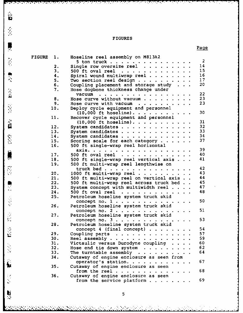
FIGURE 1. Hoseline reel assembly on M813A25 ton truck ........ .............. 2
2. Single row oversize reel . ....... ... 143. 500 ft oval reel . .... .......... . 154. Spiral wound multiwrap reel ......... . 165. Two section reel design .. ......... ... 176. Coupling placement and storage study . . . 207. Hose dogbone thickness change under
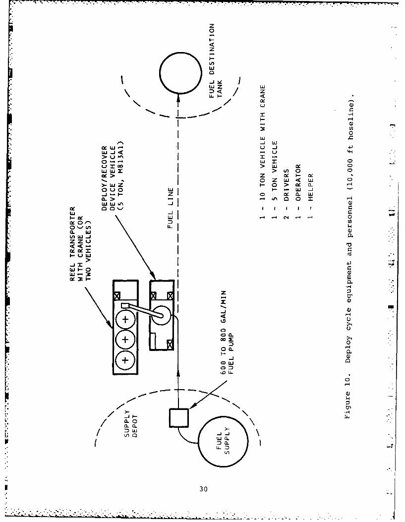
10. Deploy cycle equipment and personnel(10,000 ft hoseline) ... .......... ... 30
11. Recover cycle equipment and personnel(10,000 ft hoseline) ... ........... ... 31
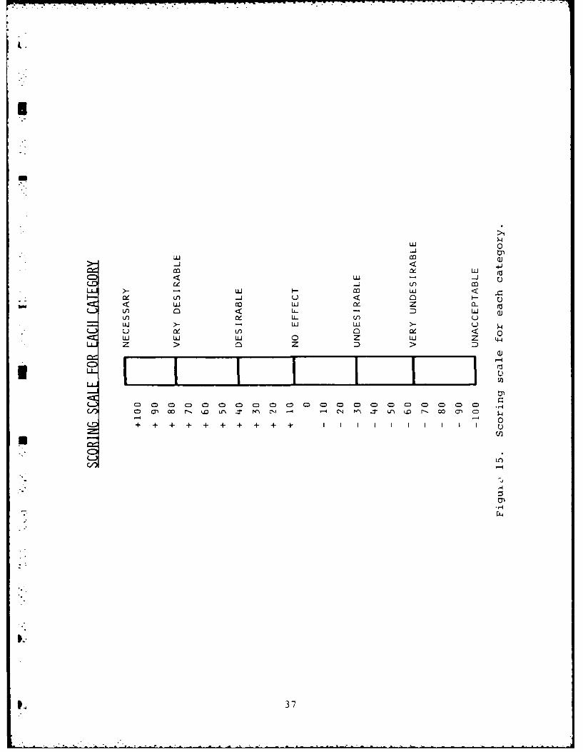
12. System candidates .... ............. .. 3213. System candidates .... ............. .. 3314. System candidates .... ............. .. 3415. Scoring scale for each category ...... 3716. 500 ft single-wrap reel horizontal
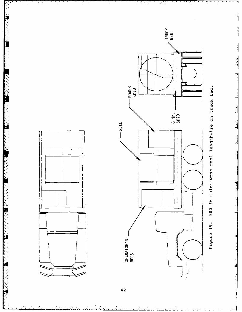
axis ....... ................... ... 3917. 500 ft oval reel .... ............ .. 4018. 500 ft single-wrap reel vertical axis . . 4119. 500 ft multi-wrap reel lengthwise on20.truck bed ...... ................ . 42
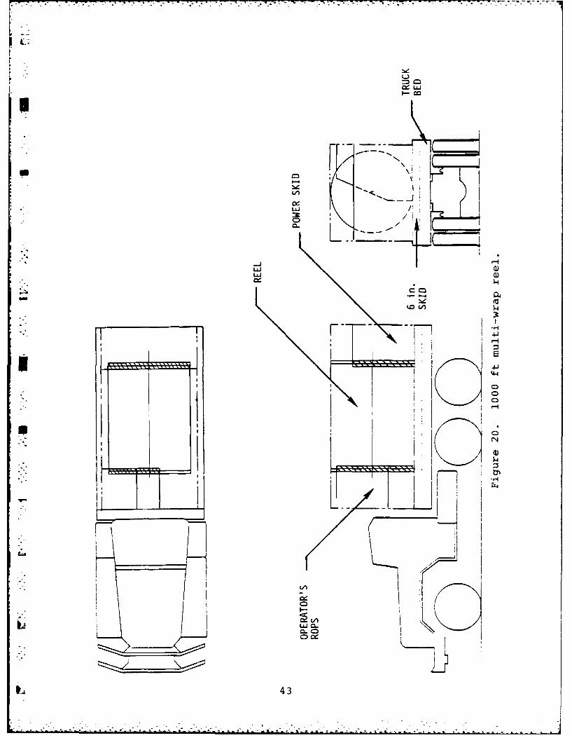
120. 000 ft multi-wrap reel ... ......... .. 4321. 500 ft multi-wrap reel on vertical axis . . 4422. 500 ft multi-wrap reel across truck bed . . 4523. System concept with multiwidth reel . . . 4724. 500 ft oval reel ....... 4825. Petroleum hoseline system truck skid
concept 4 (final concept) .. ........ .. 5429. Coupling parts .... .............. . 5730. Reel assembly ...... .............. . 5931. Victaulic versus Durodyne coupling . . . 6032. Hose end tie down system . ......... . 6233. The turntable assembly .. .......... .. 6434. Cutaway of engine enclosure as seen from
operator's station ... ............ ... 6735. Cutaway of engine enclosure as seen
from the reel .............. 6836. Cutaway of engine enclosure as seen
from the service platform ........ 69
5.... .. . . . . . .. . . . .. .
FIGURES (Continued)
Page
FIGURE 37. Engine enclosure with service platformin working position .. ........... 70
38. Typical panel construction. ......... 7139. Lifting provisions - sling point detail . 7540. Index rolls .................... 77 '41. Price roll assembly .. ............ 7942. Pinch roll released .. ............ 8043. Annotated copy of hydraulic circuit .... 84144. Reel drive control block diagram ........ 8647. Automatic deployment/recovery concept 8746. Operator's control panel. .. ......... 8947. Mode selection, automatic deployment
system. ................... 9048. Tiedown clamp ................. 9449. Final PHS configuration .. .......... 9750. Reel modification for addition
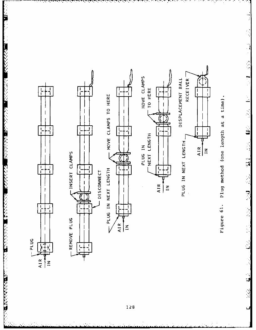
clearance. ................ 10251. Pinch roll modification. ........... 10352. Index roll bale modification ......... 10453. Pinch roll guide modification. ........ 10654. Accumulator installation ........... 10755. Clutch cooling modification. ......... 10956. Displacement pigs. ................11057. Evacuation kit....... ... . . .. .. .. ... 158. Inserting pig into adapter fitting .... 11359. Concept for adding surge loop. ........ 12060. Operator service points. ........... 12361. Plug method (one length at at time) .... 12862. Portable hose clamp. ............. 12963. Ejector assembly ............... 131
6
.FM.. -- . . . . . .
TABLE S
Page
TABLE 1. Reel summnary. ................. 192. Cycle times (itemized). ............ 263. Deploy cycle times for 10,000 ft long
hoseline. ................... 274. Recover cycle times for*10,000 ft'long
* and maintainability; productivity; and energy consumption. Each
study contributed key elements to the engineering specifications
that defined the HRA.
3.1 Hose Reel Density Study
There were three parallel efforts in this study. The first
was a volume calculation study to find out how much hose could
be stored on each of a number of reel configurations. The second
was an experimental study of hose supplied by the hose manufac-
turer, Durodyne, Inc., to determine its performance on a reel in
terms of packing density, hose dogbone size under vacuum, etc.
The third was a design study to define the minimum reel hub size
* that would contain a hose end fitting without subjecting the
hose to undue stress in the form of a sharp reverse bend.
3.1.1 Reel Volume Calculation Study - Four different reel typeswere investigated. They are shown in Figures 2 through 5.
Reel dimensions and configurations were developed for reels
holding 500 ft of hose. In all cases, the following assumptions
applied:
13
- -- 4F4T
141
......... --- 77
uio
-J <. =
Ia- '- NOW~
O sN O
co c-
C.D 0n
'-4 I
OL))
.00
LU -
c.4-
< -4
CD15
*~~~ '4co. . -
044
C~ii
~11
-o
0, 0
C~C
CV
a0
K0
-4
17
.°-.
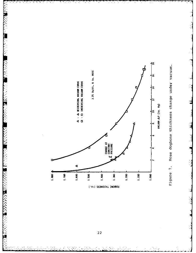
a. The hose dogbone thickness was assumed to be 1.375 in.
when collapsed. This was based on preliminary data sup-
plied by Durodyne based on a hose weighing 3.25 lb/ft.
The delivered hose had a dogbone thickness of about
0.85 in. and weighed 2.75 lb/ft.
b. The hose was assumed to lay on the reel as a flat belt
with the thickness of the dogbone.
c. Room was included for a Victualic style coupling at
each end of the 1.,se.
d. No coupling or splice was included in the middle of a
length of hose.
e. All reels were required to fit into an ISO standard
shipping container.
The results of this study are shown in Table 1. Note the
marked difference in shipping densities obtained for the various
reels (feet/hose/container). All of the results of Table 1 take
account of the conditions imposed by the reel hub study. While
the data in Table 1 is based on dogbone thickness of 1.375 in.
rather than the actual thickness of .85, the results are valid
for purposes of comparison.
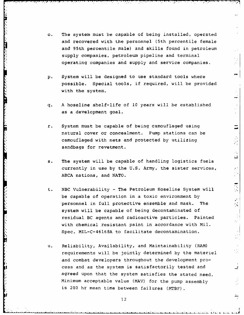
. 3.1.2 Reel Hub Study - The packing density achieved with each
of the four reel types being considered was greatly influenced
by the inner hub size chosen. The hub size had to be large
enough to contain the metal hose end with its plug and clamp.
The hub design used early in the concept development is shown
in Figure 6. The important item here is the minimum hose radius jallowed to exist where the first wrap of hose exits the hub. Too
sharp a bend is equivalent to the problem of flaking a hose
the sharp bend is a fatigue point in the hose which eventually
begins to leak. The hub of Figure 6 was used in the evaluation
described in subsection 3.1.1.
18
- .6,J
i
TABLE 1. REEL SUMMARY
Round Round Round Ovalsingle row multirow helical wound single row
Packingvol/500 ft 116 ft3 154 ft3 115 ft3 64 ft3
Reel 3-vol/500 ft 196 ft 223 ft 165 ft3 118 ft3
Hose/containerft 0 1000 ft 1500 ft3 2500 ft
Mass moment ofP inertia- lb-ft/sec2 530 202 622
19
41l
4. I
m -j i , c
czw
LU 20
Later, as a result of the experimental program, a modified
Ureel hub was designed for use in the single row reel. It is de-
scribed later in this report, in subsection 4.2.
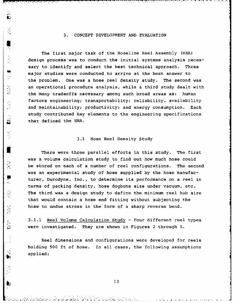
3.1.3 Experimental Hose Analysis - Two short pieces of hose
(50 to 100 ft) were provided by Durodyne during Phase I of their
subcontract. Each hose was subjected to laboratory evaluation to
determine its performance characteristics relative to packing
* and deployment. The first hose evaluated weighed 3.25 lb/ft and
displayed the characteristics shown in Figure 7. This 3.25-lb/ft
.• hose could be evacuated to maintain a dogbone thickness of 1.2 to
1.3 in. The hose wrapped on a 40-in. diam reel with 17-in. Hg
vacuum inside which was producing a thickness of 1.06 to 1.22 in.
per layer. Apparently, the curvature and tensile force necessary
to wrap it by hand were enough to flatten the dogbone somewhat.
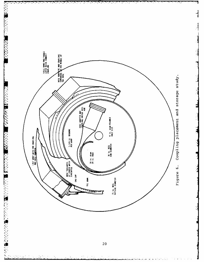
An important observation of this test was the importance of
using a collapsed hose for any automatic feed mechanism. If an
open-ended or uncollapsed hose is bent in a shape resembling the
*form it would take alongside the truck, it tends to buckle at
random points, and rises from the ground as a series of short
segments. This behavior is shown in Figure 8. Behavior of this
type would be undesirable with reeling systems which respond to
the shape of the hose as their key to maintaining the proper
reeling speed. Jerky motion could result from the random straight
*" segments.
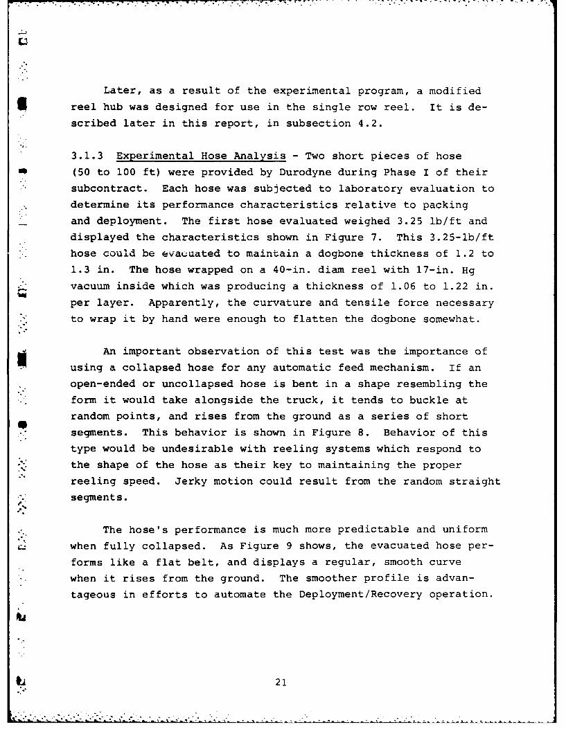
The hose's performance is much more predictable and uniform
when fully collapsed. As Figure 9 shows, the evacuated hose per-
forms like a flat belt, and displays a regular, smooth curve
- when it rises from the ground. The smoother profile is advan-
tageous in efforts to automate the Deployment/Recovery operation.
21
L)(%J 0>
LUZ
CO u
00'l0
%A VI
0
Q)
(uL) SS3NEIIHJ. 3N0990a
22
5
g Figure 8. Hose curve without vacuum.
.3o
Figure 9. Hose curve with vacuum.
23
A second hose weighing 2.75 lb/ft was evaluated later in
Phase I. It represents the reasonable limit in weight reduction
, for this size and type of hose construction. With this hose, dog-
. bone heights on the order of 0.82 to 0.85 in. were recorded
* ,at a vacuum level of 25 in. Hg. The vacuum was obtained withi a Penberthy GH-1/2 ejector similar to the GL-l being provided
with the Petroleum Hoseline system. The vacuum level was also
obtained and held unchanged for 40 min using Victualic-type
* seal gaskets. The hose wrapped on a 30-in. diam reel produced
layer thicknesses averaging 0.85-in. thick. The dimensions of
this hose proved to be the measurements which prevailed in the
final hose delivered with the Petroleum Hoseline System.
3.2 Operational Procedure Analysis
An operational procedure analysis was done to isolate and
quantify critical parameters of the deployment/recovery process
and establish realistic goals for the design process.
A basic time study showed that the truck is not a major factorin the overall deployment rate. Taking into account the need to
operate off the.road, a fundamental constraint of 7 mi/hr was
initially put on the truck's speed. This represents top speed
in first gear with the manual transmission of the M813A truck
" in high range on the transfer case. Several benefits are
obtained from this. The principal one is that gear changes are
not required during laying a hose. The transmission can be put
in first gear, high or low range, and left there depending on
- the terrain. With this simplification, acceleration and deceler-
ation rates are more predictable. The deployment can also utilize
• a less skillful operator with this simplification.
An important aspect of selecting the truck speed is that
*the rate at which the hose must be discharged or recovered
24
can then be determined. This has importance in defining the
hose reel drive. In conjunction with such variables as reel diam-
eter, hose tension, acceleration profiles, and reel inertia, truck
speed determines the reeling power required.
During the operational procedure analysis, the truck accelera-
- tion/deceleration profile was defined to be a speed of 7 mi/hr
obtained at a distance of 50 ft from a standing start. Constant
acceleration was assumed.
Once the truck speed, and thus the peak deployment/recovery
* rate, had been defined, an overall deployment rate could be devel-
oped using time simulation techniques. In the course of developing
the simulation data, the subtleties of laying a hose were further
exposed. As shown in Tables 2 and 3, it became clear that the
S--dominant factors that governed the deploy time were the time to
change reels and the time to remove and install couplings and end
plugs. Obviously if more hose can be carried on-board, the number
of reel changes can be reduced. In this case the coupling/
uncoupling time is the single most important factor affecting
deploy rate.
Referring to Tables 2 and 4, it is seen that the single most
important factor governing the recorery rate is the time required
for fuel evacuation. The relative signicance of the reel change
time, hose threading and coupling times are seen to be dependent
on the reel configuration, i.e., the amount of hose carried
on-board the HRA.
-Another item of signficance, closely associated with loading,
was the amount of time required to thread a hose through the HRA
index rolls and pinch rolls.
The various elements of the deployment/recovery cycle that were
identified during the operational procedure analysis are shown in
Table 2. The items of equipment found to give the best simulated
IL 25
TABLE 2. CYCLE TIMES (ITEMIZED)
CYCLE TIMES (ITEMIZED)
1. DEPLOY CYCLE TrMES
Time (sec)
1.1 Reel Change
Position trucks 30Move lift over reel (empty) 10Hook to lift 20Lift and swing over 30Unhook reel 20Move lift to full reel 10Hook to full reel 20Lift and swing over 30Position and place full reel 20Unhook full reel 20Fold reel out of the way 10Total reel change time T-O
300-ft Hose 500-ft Hose
1.2 Deoloy Hose
Unhook outer coupling 10 10Thread the hose 20 20Clamp hose end and remove plug 45 45Couple the hoses 60 60Remove clamp 10 10Deploy the hose 35 50Unthread the hose 20 20Total deploy hose TOT -M
2. RECOVER CYCLE TIMES
2.1 Evacuate Fuel (one hose at a time)
Clamp end of hose 10 10Install rubber ball and end plug 60 60Hook uo compressor, unclamp hose 15 15Evacuate 1 length, 70 ft
3/min 103 171
Evacuate 1 length (400 ft3/min) 18 30
Clamp the ball 15 15Unhook compressor 10 10Bleed the air 18 30Uncouple the hoses 30 30Plug end of hose 60 60Total evacuate fuel, 70 ft
3/min =321 M
Total evacuate fuel,(400 ft3/min) 236 260
10,000-ft
2.2 Evacuate Fuel (10,000 ft line)
Clamp end of hose 15Install ball ejector 60Hook up compressor 10Evacuate the line, 70 ft
3/min 3428
Evacuate the line, 400 ft3/min 600
Bleed the air 400U hook compressor 10Unhook ball ejector and receiver 45Total evacuate fuel, 70 ft
3/min 3968
Total evacuate fuel, 400 ft3/min 1140
300-ft hose 500-ft hose
2.3 Collapse the Hose (70 ft3/min)
Hook up ejector 10 10Hook up compressor 10 10Pull vacuum 103 171Unhook compressor and ejector 20 20Total vacuum 143 211
2.4 Recover the Hose
Thread hose end 30 30Secure hose end 30 30Pick up hose 35 50Unthread hose 20 20Secure hose end 30 30Total Recover 145
26
cc 4= H 0 Cq 0
a.I 000' 0 C
E-1J
0 LU W
x --
- 04
E- w C - C. -
0 (Dom -S.
0 0 -%
>4 C=.
>4 V) 0
x - (- 0:*U 0. z : I
0 4< w, 0-0
E-4 CD a
CN z w
27 - >-
U)-CLLL r-f LCn 00 :
~CCN C:)Nr- Lrr- NrrLr
LU)
I-
4LLLC) L.o C 00EnC) I M r0iL((O N r CN
0 C) rn~ CN NA r
0 z_ _ _ _ _ __
LU CLE-4 0,:
-L r No)u ll )L -- a 0r
j D NU )l -
05C)N l l L
u U
C/) CD.V))
>4w =- ZLLLL) 0 C/) CD C)C)-V
z 0 (Air- zC
w0 mL 0 > 0o~~~~L Cr-..) <U 0C
F- <. - WO 0U :0p
E-40 = U> 0 o-U - zw J = Z L
U- wJ C/ U) i U- <ui*~~ w <. LU W I-
*~ 0U <CZ- ~) C)
LU cli t U- LJ M
W u4ZO
280~,.ZW I-A
rates are shown in Figures 10 and 11. The results of the simula-
tion for a single 500-ft hose reel, and the final design consisting
of two dual wrap reels containing a total of four 500-ft hoses are
shown in Tables 3 and 4. (The evolution of the design will be
covered in more detail later.) The calculated deployment time for
the design shown in Figure 1 is 1.5 hr for 10,000 ft of hose and a
- vehicle speed of 7 mph. The recovery time is 4.5 hr for 10,000 ft
using only the air compressor on-board the HRA skid itself to purge
the hose of fuel one length at a time. With a supplemental3400 ft Imin air compressor used for purging, this time could be
reduced to 2.4 hr. The difference between deploy and recover is
* largely the time necessary to clear the hose of fuel and collapse it.
The time to evacuate fuel from the hose and consequently the
recovery rates is influenced by the length of hose to be evacuated
*in a single step. If several 500 ft lengths remain coupled together
and are evacuated in a single step, the evacuation time can be reduced.
m 3.3 Fundamental Arrangement Study
The third concept development study of the initial systems
analysis phase was concerned with the basic skid arrangement and itsimpact on the overall project. The seemingly simple task of select-
ing a reel and positioning it on the base had a profound effect on
all other aspects of the machine's production and use. Nine dis-
tinct skid system candidate concepts were generated and evaluated
* for their merit in a variety of categories. All were restricted to
discharge their hose off the right rear corner of the skid.
The nine candidate skids are shown in Figures 12, 13 and 14.
Figure 12 shows three variations of a single wrap reel on a skid.
* Figure 13 shows three possible configurations for a skid with a
reel carrying 500 ft of hose in a spiral-wound multiwrap configura-
tion similar to that shown in Figure 4. Figure 14 shows a group
of skids with a 1000-ft spiral-wound multiwrap reel.
29
-
DzI-
ac wi
0 / -0 UUU U)> A
_j - I- . -4 L
U) -
Ie 0 l0I % .) V)LLi
W LI -
I- L Li (0> 4-ui
LLji >u0IU z 3c
I~~~i 0a.aI L
00'00 I I ID 0
0. a. U
1-ULJ LL.
WI-0I
4 -4
a.0
oo
03
Dz
LL <
I - U
T: H
LU
IL -i <U0> o ,
uui = 0 > cn cc,,-. . I >Z W V)
)- LUZ 0. H > CD-Su 0 LUL H- - LU 1
_j-H z CD cl CL u-L >-4r0O
ftU -J 0UL
LU 0
UO LLJ
CL HU J I4
(A -U -z Z U
L) C)
00
Q)
< -
CDC-
I. a.
SYSTEM CANDIDATES
CANTILEVERED SINGLE WRAP ROUND
.°
VERTICAL AXIS SINGLE WRAP ROUND
CANTILEVERED SINGLE WRAP OVAL
Figure 12. System candidates.
32
SYSTEM CANDIDATES
a -.
500 Fr TRANSVERSE AXIS SPIRAL WOUND
a-f
S
500 FT LONGITUDINAL AXIS SPIRAL WOUND
500 Fr VERTICAL AXIS SPIRAL WOUND
Figure 13. System candidates.
33
SYSTEIM CANDIDATES
1000 FT TRANSVERSE AXIS SPIRAL WOUND
1000 ' LONGITUDINAL AXIS SPIRAL WOUND
1000 Fr VERTICAL AXIS SPIRAL WOUND
Figure 14. System candidates.
34
It is immediately obvious that the space utilization differs
in the nine concepts. Some leave virtually the whole skid avail-
* able to mount auxiliary subsystems such as the power plant and op-
erator's station; others leave little room for these items. A
great number of similar observations can be made about the nine
configurations. A way was needed to consolidate these observations
and rate the skid systems for their overall accommodation to the
problem of laying a hose in a military environment. A matrix eval-
uation technique was selected to measure this overall suitability.
A group of 20 general categories of performance were es-
tablished through reference to the contract and through the
combined experience of the design staff. These categories were
weighted as to their relative importance to a final design by
four experienced engineers on the basis of 100 being most im-
portant and 0 being least important.
The composite chart of the chosen categories and their
resulting weights is shown in Table 5.
Each of the nine candidate skids was then scored in each
* category by each engineer using the scale of Figure 15. For
each skid, each engineer created a total score by multiplying
each category score by its weight and taking the sum of the
weighted scores. The relative ranking of the nine evaluated
skid arrangements is shown in Table 6. Several trends are
detectable here. Side-mounted reels were judged best. Single-
width reels were judged best. The 500-ft version is of the
*spiral-wound multiwrap reels were consistently better than
the 1000-ft versions.
Concept drawings of a number of the nine skids were made
showing the machinery mounted on a 5-ton M813A2 military truck.
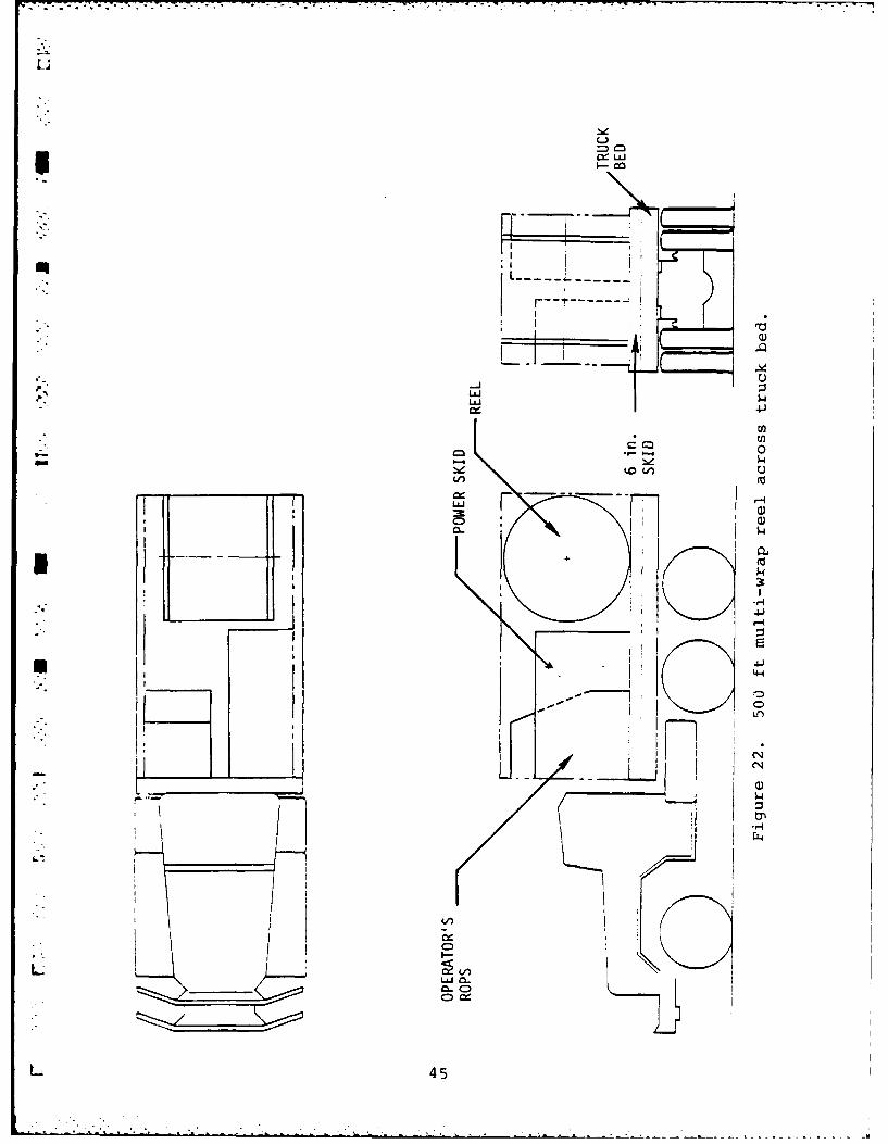
These are shown in Figures 16 through 22. From this group of
drawings, the decision to present Figure 17, the oval reel,
and Figure 19, the 500-ft spiral-wound, multiwrap configuration,
35
LU
H X -
u LuI H F
0 LU LL UlA I DzI > Lu
<1 LuI < <- H
-0 0 < LLHH 0 - - LL 0 U
0 CL < < < LuJ Z I Luu y Lu LA) < Lu
wz u Lu Lu LL - : <
: UlA 0 0 LA z 3 LA) C.
0H
4: 00D r. C14 CD r. 0C C) co
Lu
E-4
Lu
0
L) 0 Lu- -JLuJ >- U V)
H- )- - H Z C< Ho - C 0 Lu Lu <L) -j < 0 - -1 2 Lu H
- CO - L - > H -
< -j H - I 0 LU u UlA- - Z Z- Lu LuJ -j LU Z
Lu < Lu) UY - U > U-4L > < JL LA u Lu H
36
-J0
-AJ co
cc CALL
CA J F- 4o 0L4i co LUJ Z a
C) < 4L D LUJ
LU >--LU LUJ uu CA 0 w < oLU LUJ LUI 0 z LU Z 4-
ZL z >ZD>D
F- -4
-4 0
-4
37
'I-
LL LL LL LL LL LU LU LL LL
CD CD C) 0 0D CD 0 C0
CD C- C ) C C) C) C
U11% -j\ L ~ n CD V ) L\ C
LU Z
ZL -J J - U L
cl L LU LU
0i LUJ LU-.0 > LUJ LU Q
0 F- (fl LUI LUL
H -H 3 < < x
- - LUI - - LUJ LUJ3 3 -J 0n c -i -j o c
< <LUJ LU Z H- u LO VI~ )
- _- - c- - (/) I
- - 0 0 LU LUJ L uLfl ( - -j -j
U. 3 3 3LO j -1j .J -
- - LU D D DD
38
4-4
0N
~-~) co 0
41
4a
39
7.1
IINN
C)
400
x
-LUJ 4-J
LLJ
Q)
41
4-4
0
I -4
L77
7
41
C4-)
LLAJ 9
-- 4 J
04
-4J
LUn
:3
_____ ____ ____ ___
___ a--a-_ C)
I w
42w
LLIA
U 04
oV)
CoN
zzz-
432
I-J
ccA
FU iI N-Ii
wo I
o cm
~41
L&.I4
Qi)
Ko44
44-
JL-- wC
[2U
C-)
InLii
44
U)
. ............
c-C
' ')' I
* K
C 05
45I
at the design review was made. This was based on several factors,
all developed simultaneously. First, the single-wrap round reel
could not be shipped in an ISO container. As this was a necessity,
the round single-wrap was eliminated.
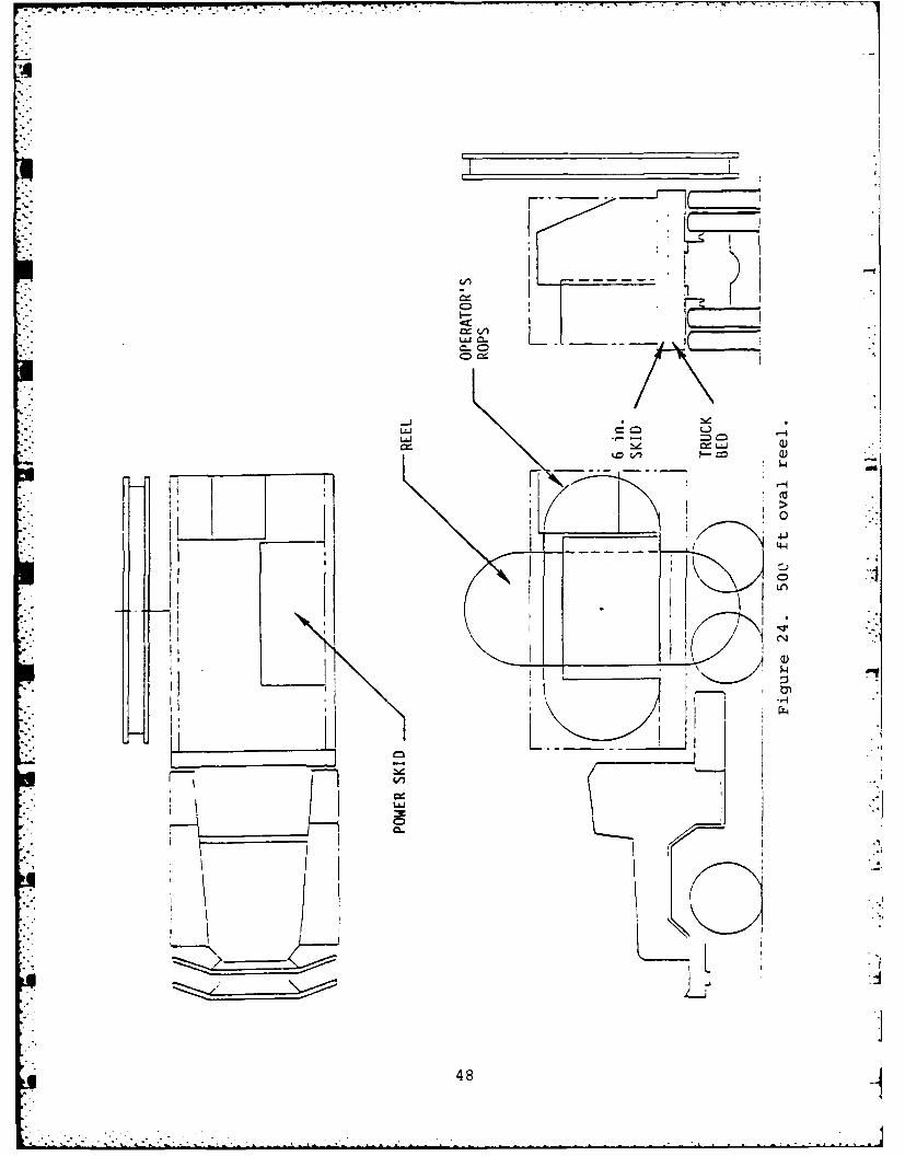
The highest-scoring remaining skid concept was the single-
wrap oval reel. It, however, required clearance greater than
11 ft vertical to rotate, and would present problems in passing
through bridges, tunnels, and the like. Its inherent simplicity
dictated that it be offered nonetheless, for it minimized hose
handling and was simple in construction.
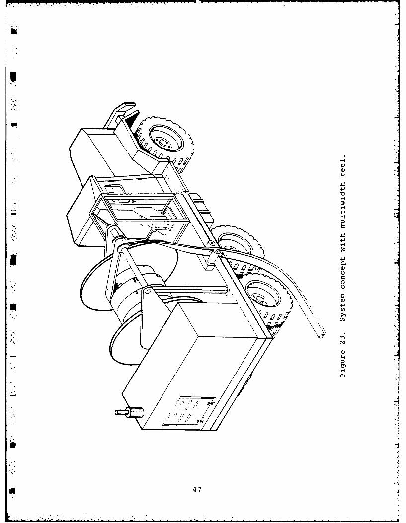
To provide for the possibility that the clearance problem
would be judged critical, the best scoring multiwidth concept
was developed for comparison. Its development at the time of
the first design review is shown in Figure 23. The competing
design was Figure 24, the oval reel concept.
With the evolution of the two concepts, the inital concept
* development was presented to MERADCOM for critique. The outcome
of that meeting was a new concept which became the concept
implemented in the detail design phase. The revised concept's
" genesis is described in the next subsection.
3.4 The First Design Review
In December 1980, the design team presented their concept
studies to MERADCOM for critique. In the course of the dis-
cussion, the simplicity of the single-wrap reel concept was
judged highly desirable in making a reliable machine. The re-
quirement to provide a minimum of 500 ft of hose on each reel was
relaxed to stimulate discussion. This led to the observation
that shorter hoses increase the time to lay a hose, because more
reels must be moved. Putting more than one piece of hose on a
reel would remove this constraint, however.
46
- -..---~--.-~---.~----- -~ -
5
U
a)a)
4-J'0
_ 4-J
4-'
S0
C)
U
p. C'.'
a)
-I~L4
Iii
i 47 .1*1- II
C--
r II)
CLL
I I48
Gradually, a new concept evolved which had the simplicity
of a single-wrap reel combined with the storage capacity of
5 the spiral-wound reels. It was, in retrospect, a derivative
* of the third and fourth scored skid concepts - a vertical axis
* group of single-width reels. The first concept drawing generated
* is shown in Figure 25.
The growth of the unexpected concept necessitated a period
of study to find the most practical configuration for the idea.
* A second design review was ultimately required to solidify the
concept and allow for detailed drawing to begin. The following
subsection describes the evolution of the final concept.
3.5 Resolution of the Final Concept
Immediately after the first design review, a series of four
variants on the new concept were laid out for analysis. At this
time, the primary design emphasis was on maximizing operator
and crew efficiency.
The first variant is depicted in Figure 25. Here, a crew of
* two men is required to operate the equipment. The skid operator
* could only lay hose from his position in the right front corner
* of the truck bed. A second man was required to mount the rear
platform to change reels and thread the hose over the laying
rollers. The concept as developed was collapsible to the length
* of the existing M813A2 truck bed for road transport.
To improve crew efficiency, a second concept was proposed.
This is shown in Figure 26. Here, the hose loading and threading
operation has been shifted forward to where the operator can
perform this task in addition to laying the hose. This concept
also could be contained within the length of the truck bed.
49
404
4J4
02
4J
04
)
500
S71
41)
>1
C-)
02
C)
73
51.
Figure 27 shows a third variant proposed to get the skid
operator away from the truck's exhaust stack and facing in the
direction of travel, as opposed to sitting across the bel of
the truck. This concept could not be contained in the length
of the M813A2 bed, and required an overhang of around 1-1/2 ft.
Furthermore, access -co the engine was severely limited.
A fourth variant, shown in Figure 28, was finally developed
to overcome some of the difficulties inherent in the third
* variant. The engine of the third variant is almost impossible
to service if a reel is in place. In the fourth variant, the
daily maintenance points are accessible through doors on the left
side of the skid. Operator comfort in the fourth variant was
*. thought to be improved by designing a standing operator's station
so that the operator's legs would cushion him from the vehicle
*excursion that takes place so far from the pitch center of the
vehicle. An overhang of 2 ft off the truck bed was necessary
to implement this concept.
At a second design review, held on 27 April 1981, the
merits of the four concepts were discussed. The variants of
Figures 26 and 28 were presented as 1/8-scale moa]els. The fourth
variant, Figure 28, was selected as the preferred concept.
As a result of reductions in hose thickness achieved by
Durodyne during their Phase I work, the preferred concept for
*the Hoseline Reel Assembly (HRA) was judged capable of carrying
and deploying four 500-ft hose lengths before changing reels.
A pErformance capability considerably greater than that pro-
jected early in Phase I was thus achieved by the selected con-
cept. During the concept development stage, a simplifying pro-
* cess also took place which reduced the complexity of the Hoseline
Reel Assembly, improving its inherent reliability. Section 4
g will describe the final design configuration of the HRA and
discuss its capabilities.
52
-
c4j
4-1
C-4
Q)
4
U 53
w rrw-v--x---r -u--v - . -~ - ~
'I- - -.-- --
.J-J
C)U
r
-H
- - -- -- T--t-- .~j.
0
C)C-)
0U
H
CC
C.)0
-4J
C)4~J
C)
C)CC0
0C)
0
C,
_____ _____ C)
0U.'
-HC'-4
54
. 4. SUBSYSTEM CONFIGURATIONS FOR THE PETROLEUM HOSELINE SYSTEM
S
Once the concept configuration, which was shown in Figure 28,
had been selected and approved, the various subsystem components
could be detailed. The rest of Section 4 is devoted to a des-
scription of the final designs developed for these subsystems.
Design analysis numbers are provided at appropriate points in
" the narrative.
4.1 The Hose
The 6-in. petroleum hose developed by Durodyne, Inc., during
Phase I of their subcontract is, of course, a major element of
the Petroleum Hoseline System. The hoseline development effort
is discussed in Section 9; only those features of the hose which
impact the Hoseline Reel Assembly will be discussed here.SThe final hose configuration weighs 2.75 lb/ft. The 2000 ft
of hose carried on the Deployment/Recovery Device thus weighs
5500 lb, exclusive of couplings. As loaded on a reel, each
end coupling consists of four major parts: an adapter, a clamp
-. ring, a seal, and an end plug to hold a vacuum in the hose. The
total assembly weighs 12 lb; thus, 2000 ft of hose requires
96 lb of couplings. The adapter is an aluminum cylindrical
insert clamped into the hose with band straps. It is machined
* with grooved ends to interface with couplings andgaskets
conforming to MIL-C-10387. A standard Victaulic( seal is
used. The coupling (or clamp ring) is a low profile aluminum
split ring coupling having a uniform outside diameter. The
internal dimensions of the coupling comply with MIL-C-10387.
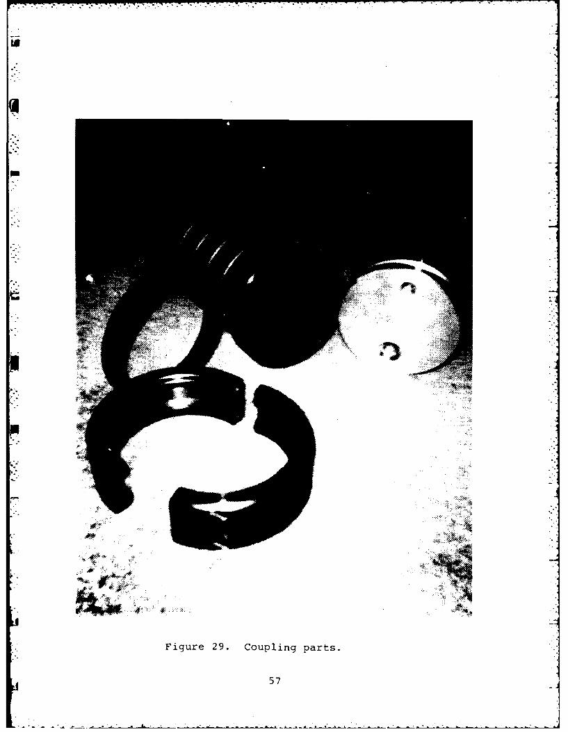
* The basic end plug (shown in Figure 29 with other coupling
components) has a circumferential groove machined in accordance
with MIL-C-10387 to mate with the coupling clamping. The end
clamp ring plug is fitted with a quick disconnect for attaching
55
the air hose or an ejector and a D-ring which are not shown in
Figure 29. The end plug provides the necessary sealing to ensure
that the vacuum in the hose is maintained.
The collapsed hose, with vacuum of 15 in. of mercury, packs
on the reel in layers approximately 0.82 to 0.85 in. thick. Pack-
ing is aided by the tensile force of up to 275 lb provided by
the HRA. The tensile strength of the hose is in excess of 4000 lb~2
to sustain its rated pressure of 150 lb/in. , so this is not
detrimental to the hose.
4.2 The Reel
An important component of the Petroleum Hoseline System is
the reel which carries the hose. It must satisfy a number of
*requirements. It must be strong enough to protect the hose in
shipment and use and be as light as possible to improve handling
and reduce the installed weight on the HRA. It must transmit
- the reeling torque to the hose and resist the gyroscopic forces
imposed by the hose itself and transmit them to the turntable.
These gyroscopic forces are worthy of note. A loaded reel
*carries around 2750 lb of hose and has an outer radius of 42 in.
* Since the reels are stacked two high (described below), the
bottom reel is required to transmit the effect of 5500 lb of hose
into the turntable. The reel stack is a large vertical axis gyro
spinning as fast as 100 rpm. Under a 1 rad/sec angular precession
of the gyro, as might be introduced by truck pitch or roll, the
resulting gyro induced torque will be on the order of 14,000 ft-lb
_ about an axis orthogonal to both the rotation of the gyro and its
precession.
The number is significant for two reasons: first, strength
of components, and, second, lateral truck stability. Strength of
components is self-explanatory. Truck stability on a 15-deg side
slope has been calculated to be on the order of 18,000 to 20,000
56
tot
Figure 29. Coupling parts.
57
L -- 2W7 7 - 7- u rz .- -
ft-lb. Thus, the gyro force is large enough to be sensed by the
HRA operator and the truck driver, and perhaps large enough to
affect mission performance.
It should be noted that the 14,000 ft-lb torque is a worst-
case situation, reflecting the simultaneous occurrence of a full
reel load, a 100-rpm reel speed, and a 1 rad/sec precession rate.
All other anticipated gyro induced loads are lower than this.
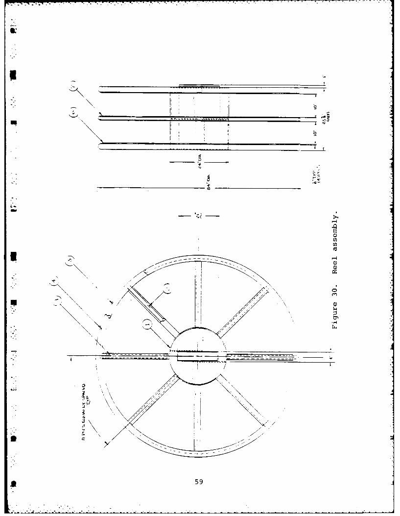
The final reel design provided the strength necessary to
* witx±-tand the forces anticipated. Each reel consists of a
24-in. diam hub and three 84-in. diam spoked flanges that are
- spaced 12 in. apart to provide slots for wraps of hose. (The
slot width was increased from 10 in. to 12 in. during DT-I
testing as discussed in Section 8). Each slot will accommodate
a wrap of up to 500 ft of hose. A rectangular steel tube, in-
corporated in the center of the hub includes provisions for
latching reels together and latching the reel to the turntable.
An attachment point for single point lifting of the loaded reel
in a horizontal position is provided in the rectangular tube.
The lifing point is designed for lifting up to three reels
locked together.
A pocket for nesting the adapter and coupling fittings is
incorporated in the hub as shown in Figure 30. The improvement
in packing density that is possible with the Durodyne coupling
* is depicted in Figure 31. Also, the lack of a sharp bend in
* the hose as it conforms to the hub is shown in this figure.
Essentially, the unavoidable distortion of the hose where it
meets its adapter is utilized to make the transition to the hub
efficiently. The sharp reverse bend common in flaking a hose
for storage is missing. This should prolong the hose storage
* life.
58
.* . . .
icn
*5
VIC7A.ULIC
DURODYNE
Figure 31. Victaulic versus Durodyne coupling.
60
The reel flanges are of tubular construction to save weight.
Since each reel is installed on the turntable hub only one way
(same side down all the time) , thin perforated sheet metal has
been added to the flange surfaces where the hose rests.
To save space, the reel flanges end at the expected diameter
necessary to store 500 ft of hose. The outer coupling is lashed
to the reel with a retaining strap. The end condition is shown
in Figure 32. With this construction, it was possible to build
a reel holding 500 ft of hose that would fit through the cargo
* door of an ISO standard shipping container. The two hose couplings
* are simply oriented away from the door edge during the insertion
and removal process.
It is important to realize that centrifugal force is a
*factor in selecting the strap to hold the end of the hose to the
reel. The hose end and first 180-deg wrap of hose induce loads
of 200 to 250 lb in the direction tangent to the rim at rotational
speeds of 100 rpm. A substantial strap is indicated. During
operation, the strap must be installed properly, too, to preventthe hose coming loose during deployment or recovery of subsequent
hoses.
4 61
10
-LJ
C-L
LUU
-Jy
uu
1 0
0~C >- 0
I
.o LU
* 0u0 U')
V)~ 0=
I< =-J a,
LU
62
4.3 The Turntable
UThe turntable and its drive are key elements of the HRA.
This assembly drives and supports the reel stack and must
resist all of the gyroscopic forces discussed in the reel section.
A low-profile Keene MTO 265 turntable bearing is the principal
support for the turntable. It reacts the loads down into the
frame weldment. The radial piston low speed hydraulic motor
that drives the turntable is isolated from all forces except
the reeling torque by this bearing.
The Sundstrand motor is capable of producing 1500 ft-lb of2torque at 1500 lb/in. This is adequate to accelerate the reel
fast enough to follow the truck as it accelerates to lay or recover
a hose. The torque capacity includes a provision for maintaining
up to 275 lb of tension in the hose at all times.
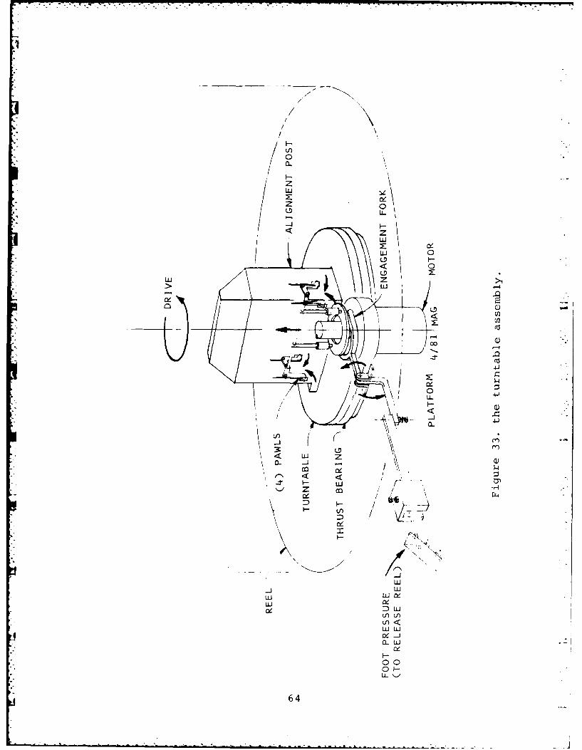
U The turntable assembly is shown in Figure 33. The large
tapered post is the drive key which fits into the rectangular
socket of the reel. Four pawls are spring-driven into slots in
the reel socket to lock the reel to the turntable automatically.
*The taper facilitates the reel's dropping over the post on uneven
ground during a reel change.
A foot pedal is provided to release the pawls while lifting
off a reel. The pedal must be held depressed while the lift is
* made. Upon release of the pedal, the pawls reset under spring
force, ready to receive another reel.
4.4 The Engine Enclosure and Power System
Contained within the engine enclosure is the power system for
the Hoseline Reel Assembly. Power is derived from a GMC
63
-)
zLuJ
0~IL
zC
Lu >D0-
LO-.4
U)
~r0 41/ ~ LL
I--
CL
L)
I-.
64J
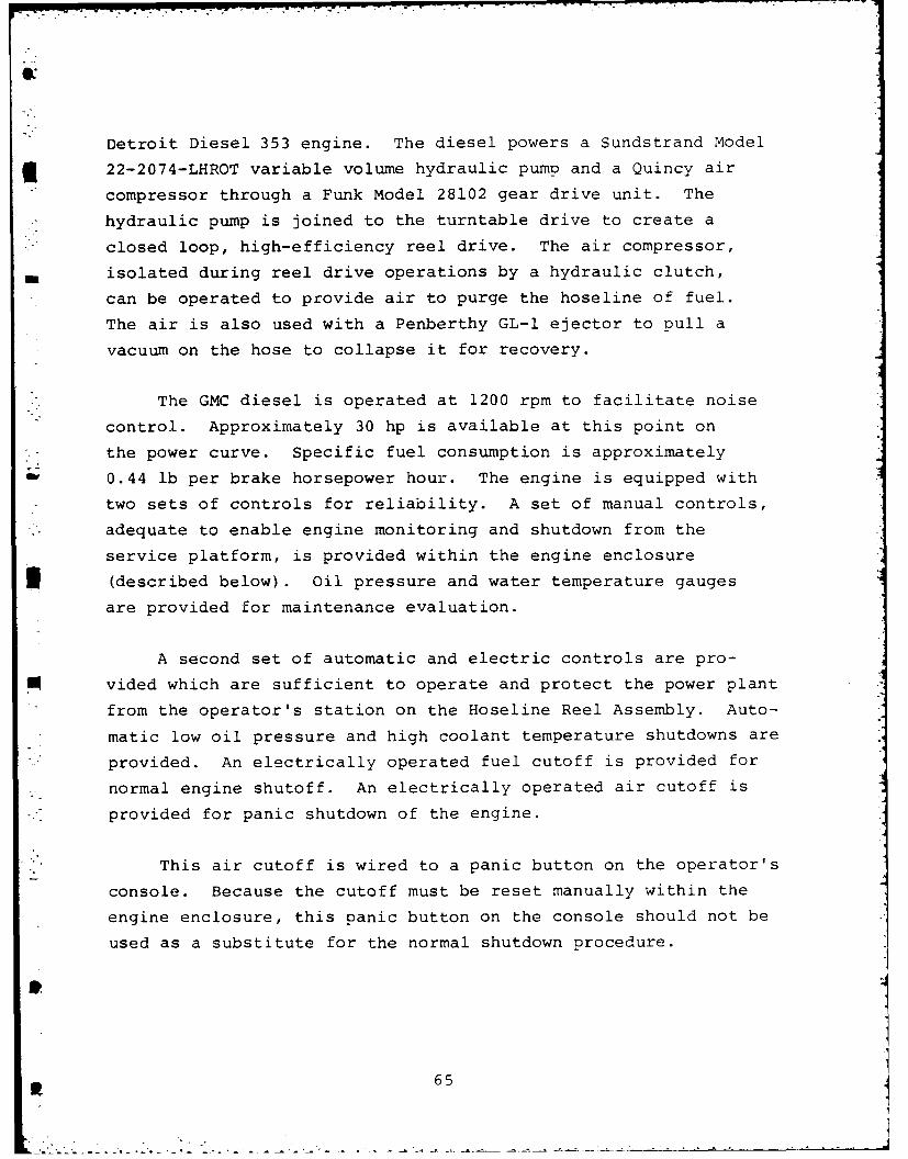
Detroit Diesel 353 engine. The diesel powers a Sundstrand Model
3 22-2074-LHROT variable volume hydraulic pump and a Quincy air
compressor through a Funk Model 28102 gear drive unit. The
* hydraulic pump is joined to the turntable drive to create a
closed loop, high-efficiency reel drive. The air compressor,
- isolated during reel drive operations by a hydraulic clutch,
can be operated to provide air to purge the hoseline of fuel.
The air is also used with a Penberthy GL-l ejector to pull a
vacuum on the hose to collapse it for recovery.
The GMC diesel is operated at 1200 rpm to facilitate noise
control. Approximately 30 hp is available at this point on
*. the power curve. Specific fuel consumption is approximately
;0.44 lb per brake horsepower hour. The engine is equipped with
two sets of controls for reliability. A set of manual controls,
adequate to enable engine monitoring and shutdown from the
service platform, is provided within the engine enclosure
3 (described below). Oil pressure and water temperature gauges
are provided for maintenance evaluation.
A second set of automatic and electric controls are pro-
vided which are sufficient to operate and protect the power plant
from the operator's station on the Hoseline Reel Assembly. Auto-
matic low oil pressure and high coolant temperature shutdowns are
provided. An electrically operated fuel cutoff is provided for
normal engine shutoff. An electrically operated air cutoff is
-* provided for panic shutdown of the engine.
*' This air cutoff is wired to a panic button on the operator's
console. Because the cutoff must be reset manually within the
engine enclosure, this panic button on the console should not be
used as a substitute for the normal shutdown procedure.
6i 65
I?'47
An electrically operated throttle is provided to synchronize
the engine speed to the work cycle. The throttle is a two-
- position control: idle and power. The engine has a governor to
match power output to engine revolutions per minute setting
(throttle setting). The throttle setting, or rather a variation
of the throttle setting, is not a control provided to the operator
directly. By selecting his desi-ed mode of operation on his
console, he gets the proper throttle position. This simplifies
his console and ensures that adequate power will be available to
meet demand.
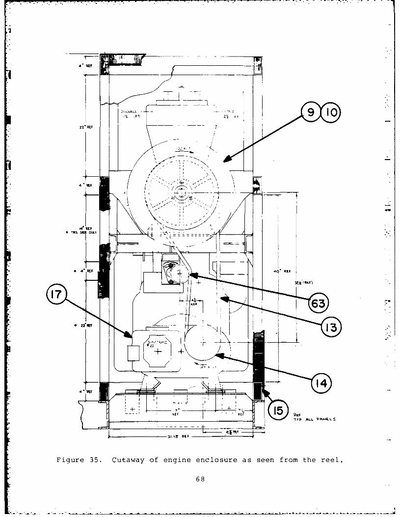
Figures 34 through 37 show the configuration of the engine
enclosure and its contents. In addition to the major items
mentioned above, the enclosure contains a number of other essen-
tials, such as the engine air cleaner, the engine silencer, and
the hydraulic oil cooler.
Care has been taken throughout the design of the engine
enclosure to provide acoustic attenuation to ensure meeting the
specified requirement of 85 dBA noise level at the operator's
station. As was mentioned earlier, the diesel runs at 1200 rpm
to reduce noise. A special muffler, termed a hospital silencer,
is used to cut exhaust noise. An oversize air cleaner is used
to reduce intake air noise. The engine enclosure itself is a
sophisticated acoustic enclosure.
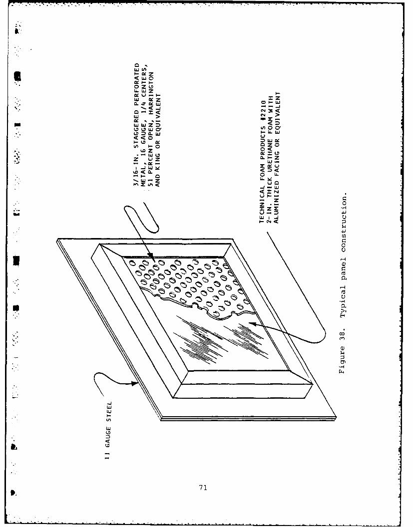
All the side panels and the top of the enclosure are con-
structed as shown in Figure 38. A 2-in. thick acoustic attenuat-
ing foam is sandwiched between two pieces of sheet metal to absorb
as much sound as possible. All openings on the enclosure are pointed
away from the operator so that transmitted noise is not focused
in his direction. The need for intake air and cooling flow
* 66
(0
-
0
N . 0
g
42
L2L~
0
--
Tr2~r --~ - - -w___
____ w
__
. , 0
- - . 0
S -
--
. - C).~ ~- U,
/
0K A-*1~~~
UU
-..
-
- r"]
V. C)
0~>1
42U
.~j.
a)
H
*
67
4 'RE
22* RIF
V M O:OV: (z\
4" WE 40 EV
14t14
~R F
Figure 35. Cutaway of engine enclosure as seen from the reel.
68
4-4
4 J
-4
Qk 4i
4j
69
0
-)
-404
700
w00
0 .JO
U.LLW Z
LU eZ OLL
O4L LL >
LU >
Q) U) L CD, ( 00vI-- LL LU
V) 0QZ-. LU -. I=Z
0 L0
-J -4
4)
I U
LU4
71J
prevents sealing the enclosure. At the recommendation of MERADCOM
acoustic specialists, all air passages contain a right angle turn
to make the acoustic absorption as effective as possible. As
* discussed in Section 8, the louvered openings for air flow should
be modified to eliminate line of sight from the interior of the
enclosure to the outside.
As a sidelight to acoustic treatment, MERADCOM personnel
pointed out the desirability of a pusher fan for the engine, to
ensure that warm cooling air exists the enclosure as quickly as
possible. This reduces engine operating temperature, which is
, always desirable with a closely cowled engine. Consequently a
pusher fan has been used.
To reduce structure-borne noise, the engine is mounted
on sound absorbing pads.
With the acoustic treatment described above, the sound
level at the operator's station was 89.5 dBA with the HRA engine
running at 1200 RPM and the truck engine off. Futhermore, the
engine tended to overhead during air compressor operations under
high ambient conditions. Both of these problems may be corrected
."by modifying the air openings as described in Section 8.
A futher feature of the engine enclosure is shown in
Figure 37. The routine service points on the engine, Funk box,
and compressor must be made available for daily maintenance.
Space utilization prevented access to these points from the
operator's side of the engine enclosure. Therefore, a fold-
down service platform was provided on the left side of the
Hoseline Reel Assembly skid to perform maintenance. The com-
ponents within the upper area of the enclosure can be accessed
by removing the two upper enclosure panels. The two most fre-
quently used lower panels are hinged for convenience. The plat-
form is provided with guard rails and toeboards for safety and
is constructed of aluminum for weight reduction. This allows
72
i
a single soldier capable of lifting 30 lb to raise the plat-
3 form into its storage position and secure it. The platform
is rated for 300 lb live loads and is so marked.
37
".73
8.
4.5 Frame
The Hoseline Reel Assembly frame is a large structural
weldment that serves as the mounting base for all other sub-
systems. For example, it seals the bottom of the engine enclo-
sure to prevent sound propagation. It is the reaction base for
the turntable, and transmits all the forces generated above
the turntable down into the truck bed through the truck tiedown
system. It is the base for such auxiliaries as the battery
box, the hydraulic oil tank, and the fuel tank and supports
the guide roll system which controls the path of the hose from
the ground to the reel.
It incorporates overhead protection for both the truck
driver and the HRA operator. This is principally for protection
during the lift of the reel stack. It also provides brush
protection for the operator by enclosing the operator's station
with a large mesh screen.
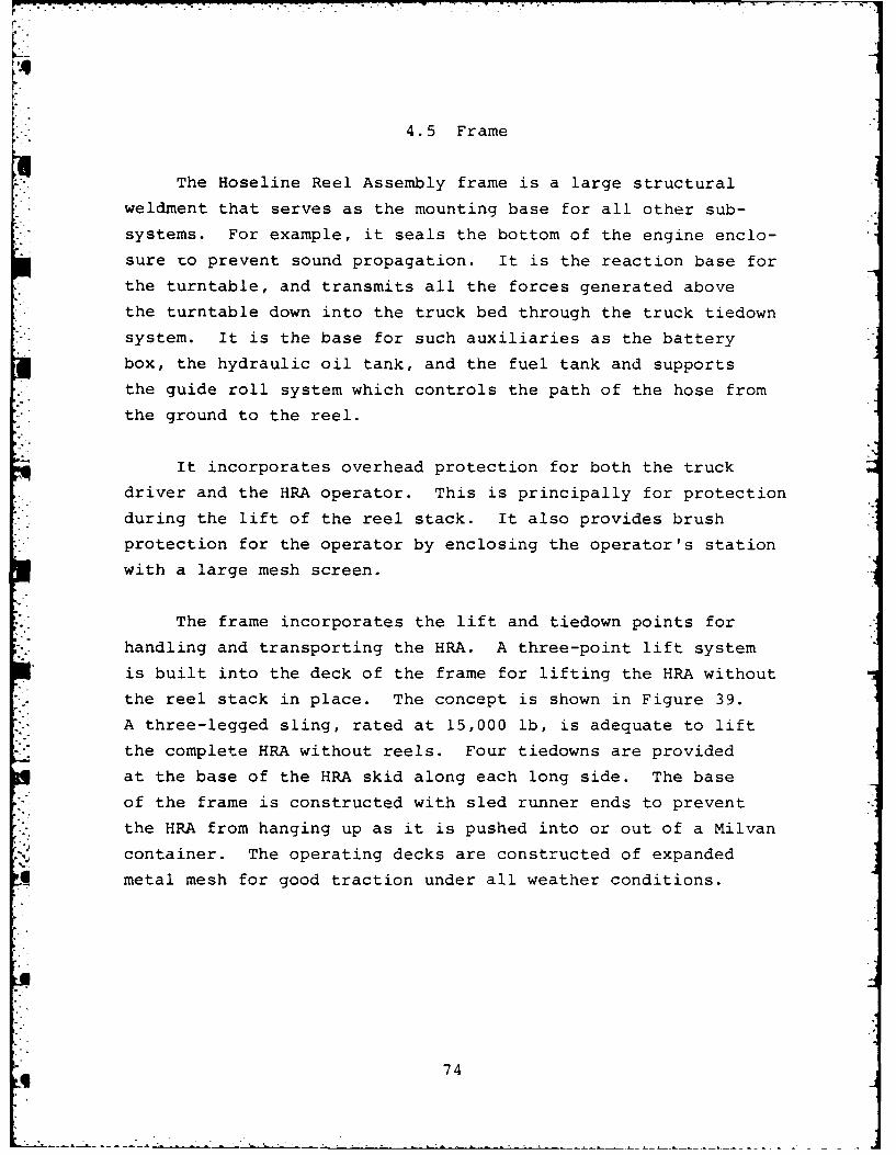
The frame incorporates the lift and tiedown points for
. handling and transporting the HRA. A three-point lift system
is built into the deck of the frame for lifting the HRA without
the reel stack in place. The concept is shown in Figure 39.
A three-legged sling, rated at 15,000 lb, is adequate to lift
- the complete HRA without reels. Four tiedowns are provided
at the base of the HRA skid along each long side. The base
*" of the frame is constructed with sled runner ends to prevent
the HRA from hanging up as it is pushed into or out of a Milvan
container. The operating decks are constructed of expanded
Iq metal mesh for good traction under all weather conditions.
9 74
-4
.
.0J
0
-44
0)
t 75
4.6 Guide Roll System
Two sets of rolls serve to define the path the hose takes
from the reel to the ground. A significant amount of design
effort was expended to create the simplest hose path possible.
The hose was treated as a flat belt, rather than as a round
tube. When properly evacuated, the hose simulates a belt nicely.
Having a belt limits the number of stable paths that can be
developed and creates other potential instabilities, such as the
tendency of a belt to develop differential tension across its
width and "walk" off pulleys.
The path developed for use consists of three turns across
*the width of the hose and one 90-deg twist. This configuration
* is stable, and does not develop differential tension between
belt edges.
As stored on the reel, the hose is on edge. The first turn
and the 90-deg twist that places the belt parallel to the ground
* is controlled by the index roll set. The second of these two
rolls also controls the turn which points the hose down toward
"- the ground. The pinch roll set then guides the hose down along
*i the side of the truck and becomes the starting point for the final
90-deg turn to lay the hose on the ground. The path which the
hose takes is shown conceptually in Figure 28.
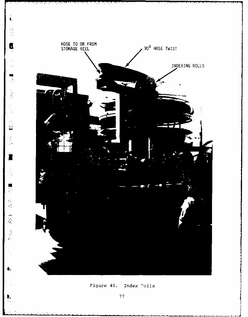
The construction of the index roll assembly is shown in
Figure 40. This roll group is required to move up and down to
remove or load a hose into each of the four reel slots. A
hydraulically-driven screw and nut assembly positions the index
roll set. Moving the rolls is a manual operation with fiducial
marks provided to indicate the proper stopping points.
26
I.
HOSE TO OR FROMSTORAGE REEL 9 HOSE TWIST
INDEXING ROLLS
I
Figure 40. Index olls
I 77
-.6
The correct positioning of the index roll is critical to smooth
operation and proper packing of the hose on the reel. The cor-
rect positions for deploy and recovery are different and are
also dependent,to some degree, on the suppleness of the hose.
Fortunately, the correct positioning of the index rolls is
quickly learned in a few hours of operation. The hose must be
threaded over the index rolls in such a manner that the hose
twists 90% clockwise as viewed from the operator's station
looking forward.
* - The pinch roll assembly (shown in Figure 41) consists of
a pair of rubber surfaced rollers through which the hoseline
passes during deployment or recovery. The rear roller is driven
via a drive chain by a Char-Lyn Model 104-1061-005 hydraulic
gear motor. The forward roller is an idler that is spring loaded
to provide the desired pinching force on the hoseline. During
deployment, the pinch rolls pull on the hoseline to take up
slack as the hoseline is unreeled, and lay the hoseline on the
ground. During pick up, the hoseline is dragged through the
rollers by the reel assembly and the pinch rolls are back driven
to tension the hoseline.
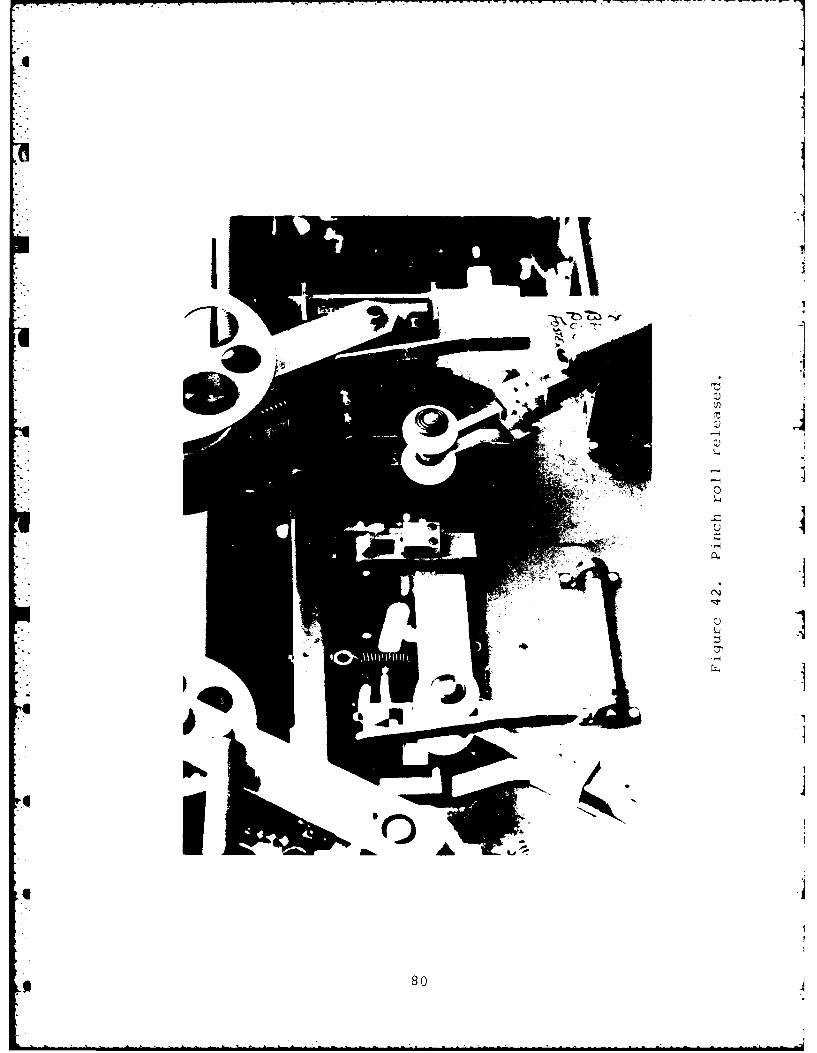
A tripping mechanism is designed into the pinch roll assembly
* to allow th'- ninch rolls to release and pivot upward (as shown
* - in Figure 42 to permit the rigid adapter fittings at the end
of the hose to pass through. The release can be activiated
manually, using the release levers provided, or automatically
when the adapter strikes the dancer roller located directly
below the pinch rolls.
* The dancer roller is attached to the end of a spring-
loaded linear potentiometer that serves to sense the shape of
the hoseline loop between the pinch rolls and the ground.
BIf the rate at which the hose is unreeled is too slow for the
vehicle speed, the hose is pulled taught against the dancer
78
.5
M)~
~.
U
. .
* :.~ * 0
Cl)U)
-4
0'-4
U U
"-4
'-4
U G)~~4
"-4
79
-I
II
0A
800
roller stroking the linear potentiometer. This sends a command
to the turntable drive system to increase the turntable reel
speed. Conversely, if hose is unreeled too rapidly for the
vehicle speed, the hose will go slack, the potentiometer will be
fully extended, the pump will be commanded to zero stroke and
M the turntable will be dynamically braked.
M
8
81
4.7 The Hydraulic System
All of the functions of the HRA are hydraulically actuated.
*This power form is easily modulaed to provide the wide range of
speed and torque needed by the various components.
There are two powered functions used to actually lay or
recover a hose. They are the reel drive and the pinch roll
drive. The variable speed requirement of the reel drive and its
need to respond to the truck's travel through a servo systemsuggested a hydrostatic drive for this component. A variable
volume pump equipped with electrical and manual controls for
displacement is connected to a radial piston hydraulic motor in
a closed loop. Either through the automatic deployment system
or through manual input, this hydraulic drive controls the speed
and direction of rotation of the reel.
While the reel is moving under the direction of the hydro-
static drive, a constant tension is maintained in the hose by
the pinch roll drive. The pinch roll drive consists of a gerotor-
type hydraulic motor driven by a constant volume gear pump.
Relief valves installed between the pump and motor ensures that
a constant but limited pressure is supplied to the motor for
torque control.
*The amount of hoseline tension during recovery can be ad-
justed by means of a pressure relief valve. Test experience
*indicated that a setting of about 500 psig is correct. The
hydraulic supply pressure to the pinch roll motor during de-
ployment is set at about 1500 psi. Also, to increase the speed
of the pinch rolls during deployment, the oil flow rate is in-
creased by supplementing the flow from cam shaft-drive pump with
oil from the main pump. This is accomplished automatically via
a solenoid valve whenever the deploy mode is selected whether
in automatic or manual control.
82
This tension serves two purposes. In picking up a hose, it
4 ensures a good packing density on the reel. In laying a hose,
it pulls the hose away from the reel and gets it off the truck.
Besides the two deployment functions, there are two ancillary
hydraulic functions. One is used to raise the index roll assembly
to reach the four reel slots. This function consists of a small
hand-operated pilot valve which controls a larger valve to deliver
oil from the pinch roll pump to the gear type hydraulic motor
raising the index rolls. The second ancillary function is a
circuit normally plugged off that allows the oil from the pinch
roll pump to be taken off the HRA for remote use. This cir-
cuit has no current purpose in the operational scenario,
but was provided for the convenience of future users at the
request of MERADCOM personnel.
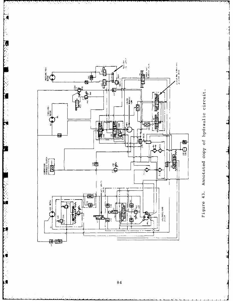
The hydraulic system in general is state of the art and is
expected to be highly reliable. Filtration to the 3w level is
provided on the charge pump circuit feeding the hydrostatic drive,
and 10 filtration is provided on the constant volume pinch roll
pump. A large hydraulic oil cooler is provided in the engine
enclosure. The cooler is positioned in the engine cooling air
flow so that it will warm the oil during low temperature opera-
tion. The recommended hydraulic fluid is mineral-base oil with
antiwear additives. An annotated copy of the hydraulic circuit
is shown in Figure 43 with the purpose of the components
identified.
83
4.
0
04
13.,
4J
84
4.8 Operator's Station and Automatic Deployment System
* Three separate control systems are provided to pick up or
*lay hose within the Hoseline Reel Assembly. Although complete
- redundancy is not provided at all component levels, the control
- loops are independent, in that with virtually any control compo-
* nent failure another control loop exists which will enable mission
completion. Examples of this independence will be demonstrated
later.
The three control loops are an automatic control system, a
manual control loop using electric controls, and a manual control
loop using nonelectrical components. Their priority of use is asb~s indicated: automatic, electrical manual, then mechanical manual.
- The mechanical manual system should be used for deployment only in
* extreme emergencies. The sensitivity of the feedback process de-
* creases with each succeeding control loop.
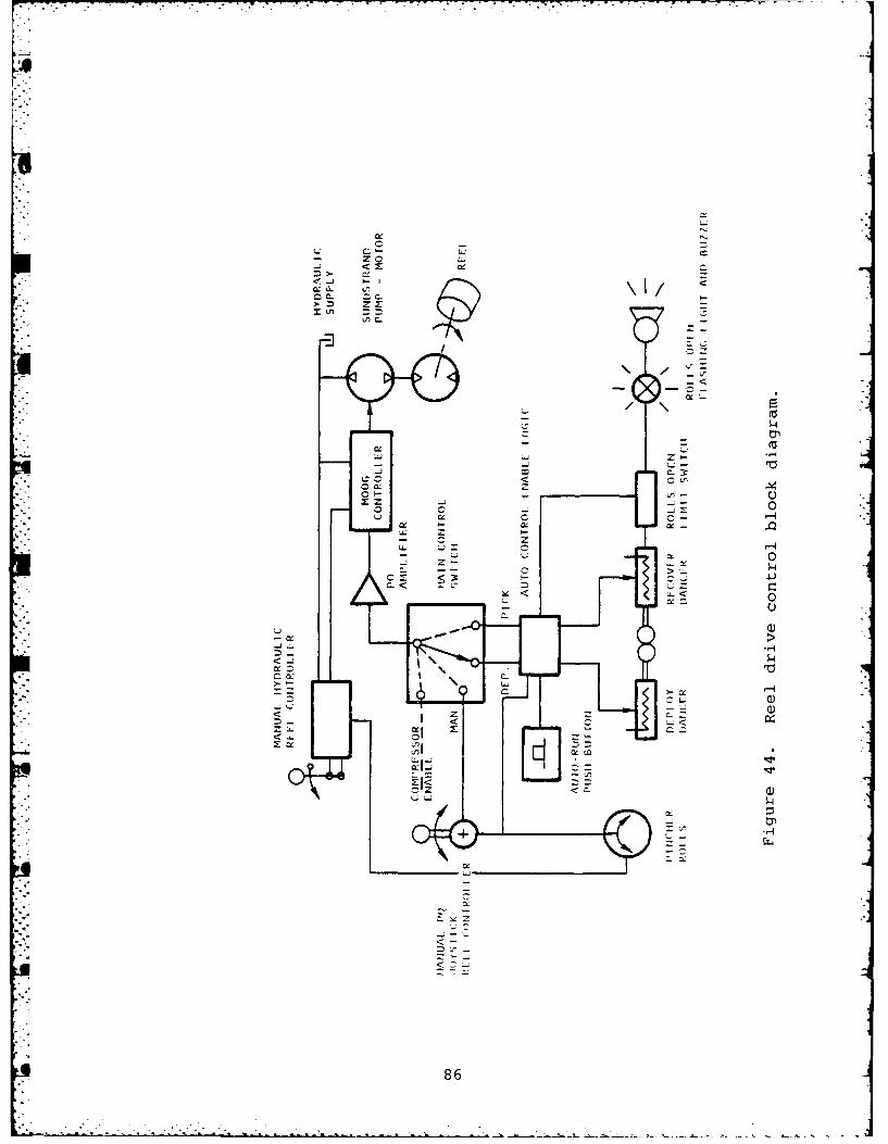
The block diagram of the col:Itrol options is shown in Fig-
* ure 44. The main control switch is the key to control loop selec-
tion. In the positions DEPLOY (DEP), or PICK, the automatic
* deployment system is in use. In the MANUAL (MAN) position the
electric joystick is available for use. The manual hydraulic reel
controller is available with the mode switch in Automatic or Manual.
The automatic control system is an electrical feedback circuit
* . using the hose position off the side of the truck as the feedback
* parameter to adjust reel speed. The concept is shown in Figure 45.
During deployment, a tightening hose loop causes the reel to
* speed up by depressing the deploy sensor (Ri). During recovery of
a hose, shown in the second picture of Figure 45, a slackened loop
permits the sensor (Ri) to fully extend causing the reel to
slow down. owing to the inertia of the reel system, reverse
85
- zo
z) x~
' Ul CI
~ i.-r
~- zc. -)-~Lz:
J~ - .c r L 4
44)
M (r
860
U PINCHER ROLLERS
TRUCK FORWARDO
DEPLOY/RECOVER
TRIP LIMIT SPITCH
E i HOSE
DEPLOYMENT
.U" TRIP LIMITSWITCH (SW2) " PINCHER
DEPLOY/RECOVERSENSOR (R1)
HOSE 1
3STOP
IRECOVERY
Figure 45. Automatic Deployment/Recovery concept.
L 87
* direction signals are not transmitted through the electrical
system to the hydraulic drive. The direction of rotation of the
reel is selected by the main control switch; speed is regulated
* by the feedback control circuit.
Interlocks are provided with the automatic deployment system
* to ensure that the pinch rolls are properly engaged prior to
* initiation of control and throughout the control period. The
engine throttle is electrically interlocked through the main
control switch as well. Automatic control is initiated by a
- START button after control mode selection. Automatic control is
* terminated by control mode change (main control switch movement)
* or by a STOP button. It is, of course, terminated by the
EMERGENCY STOP button as well, but this is an abnormal stop which
- requires special procedures to restart.
* The layout of the operator's control panel is shown in
Figures 46 and 47. Figure 46 shows the controls for all three
control loops. These will be described presently. The left hand
area of Figure 46 is concerned with the mode selection and
automatic deployment system. It is isolated in Figure 47. To
operate the automatic deployment system, the operator selects
* DEPLOY or PICKUP on the main switch. He checks to see that the
amber ROLLS OPEN light is off, then presses the button markedSTART AUTO. The engine speeds up and the dancer roll becomes
active to drive the reel in response to the truck's movement. To
shutdown the automatic system, the STOP button can be depressed
or the mode switch can be moved.
9 To activate either of the two manual control loops, the main
* control switch in Figure 47 is moved to MANUAL. When this is
* done, the electric joystick in the middle of the console of Fig-
* ure 46 is active and available for use. It is interlocked
Hose Storage Capacity: 2000 ft of 6-in. petroleum hose
Storage and Shipping Container: 20-ft Milvan orISO container
b. Operating Dimensions on M813A2 Dropside Truck(including the truck)-
Overall length: 326 in. (without winch)
Width: 97-1/2 in. (road travel condition)
Height: 138 in.
* Total Weight: 1 reel; 500 ft hose, 32,540 lb2 reels; 2,000 ft hose, 37,620 lb
c. Operating Conditions -
Maximum truck speed: 5 mi/hr
Side slope capability: 15 deg
d. Major Components -
Engine: GMC Detroit Diesel 353
Fuel Capacity: 28 gal No. 2 diesel fuel
95
. . . - , .-. . . . . . . . - - ... . . .. .
Hydraulic System: 1 Sunstrand Pump
1 Vickers Pump 4
1 Sunstrand Motor
1 Eaton Char-Lynn Motor
1 Electric Solenoid Valve
1 Pilot-operated Valve
1 Hydraulic Oil Cooler
4 Relief Valves
Hydraulic tank capacity: 30 gal
Electrical system: 24V, 2 batteries, 12V, MS35000
Hose purging system: 70 ft3/min Quincy Air CompressorGL-l Penberthy Ejector
Hose: 500-ft length of 6-in. petroleumhose manufactured by Durodyne, Inc.
Hose Coupling: Victaulic-type seal in custom ringclamp seal and couplings per MIL-C-10387C.
J
96
. . . . . .
97.
6.0 FABRICATION, ASSEMBLY AND TEST OF THE HRA
The HRA was assembled at Foster-Miller's Waltham, MA.
facility during the spring of 1982. Major subsystems and com-
ponents such as the base frame weldment, the engine enclosure,index roll assembly, and reels were manufactured by local sub-
contractors in conformance with Foster-Miller's engineering
* drawings. Five (5) 500 ft hoseline assemblies were received
from Durodyne in mid April and spooled onto three dual reels
;* at Foster-Miller.
Integration and checkout of the Hoseline Reel Assembly con-
tinued through the month of April and the controls and safety
- related features were demonstrated to MERADCOM personnel on28 April 1982. System integration and debugging continued in
May and the unit was shipped to Aberdeen Proving Ground for
DT-l testing on 2 June 1982. 4
During this period, the hydraulic system was modified to
* increase the flow of hydraulic oil to the pinch roll drive motor
when deploying hose. Because the pump for the pinch rolls is
driven off the cam shaft of the GM3-53 diesel, the available
horsepower for driving a pump is limited to 10 horsepower.
Consequently, a larger pump could not be installed to provide
the increased flow at 1500 psi. To minimize the impact on the
overall system, a system for diverting some flow from the main(turntable) pump was designed and installed. During deployment,
approximately 6 gpm of oil from the main pump is diverted via a
vented relief valve and solenoid control valve to supplement
oil from the cam shaft driven pinch roll pump. The additional
flow (a total of about 13 gpm at 1500 psi) ensures that the
pinch rolls will drive fast enough to avoid excessive slack in
the hoseline as it comes off the reel and passes over the
index rolls.
98
. ..; . .'. . ." , .', .-.= : . , .1
The only other significant modification during this time
* period was the addition of a spring loaded bail to the vertical
axis index roll. The hose has a tendency to fall off the index
. roller if slack develops in the hose during deployment. The
" bail proved to be very helpful and made the system more for-
* giving of variations in hose thickness and stiffness (e.g. the
splices) and hose tension. The design if the bail was improved
upon during DT-l as described in Section 8.
The performance of the reel control system was initially
very erratic. This proved to be due in large part to air
entrapped in the hydraulic system and the low setting of the
• "cross-over relief valves. The cross-over relief valves were
set at 3000 psi and the air was ultimately purged from the
system resulting in greatly improved response particularly in
. dynamic braking.
U A test and demonstration of the HRA was completed at Foster-
Miller, Waltham, MA. facility prior to shipping the unit to
Aberbeen Proving Ground. The results are documented in Foster-
Miller Report No. MER 0216-FM-8055-I.
99
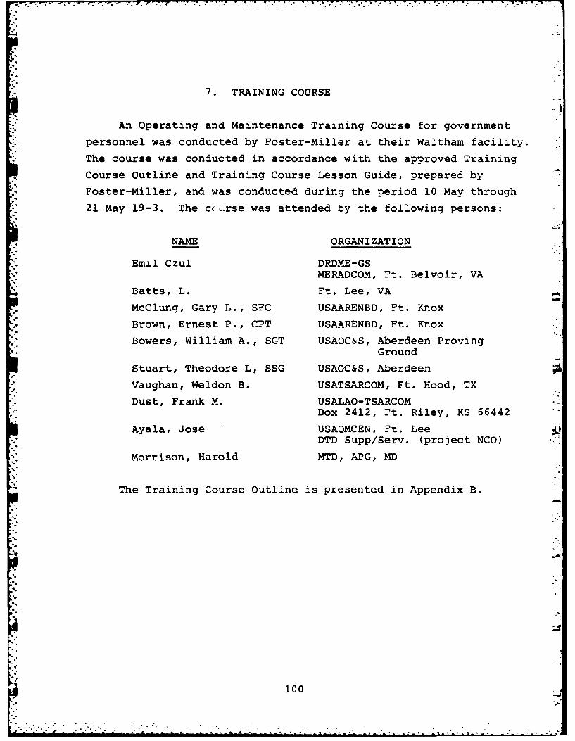
7. TRAINING COURSE
An Operating and Maintenance Training Course for government
personnel was conducted by Foster-Miller at their Waltham facility.
The course was conducted in accordance with the approved Training
Course Outline and Training Course Lesson Guide, prepared by
Foster-Miller, and was conducted during the period 10 May through
*" 21 May 19-3. The ccL.rse was attended by the following persons:
NAME ORGANIZATION
Emil Czul DRDME-GS
MERADCOM, Ft. Belvoir, VA
Batts, L. Ft. Lee, VA
McClung, Gary L., SFC USAARENBD, Ft. Knox
Brown, Ernest P., CPT USAARENBD, Ft. Knox
Bowers, William A., SGT USAOC&S, Aberdeen Proving* Ground
Stuart, Theodore L, SSG USAOC&S, Aberdeen
Vaughan, Weldon B. USATSARCOM, Ft. Hood, TX
Dust, Frank M. USALAO-TSARCOMBox 2412, Ft. Riley, KS 66442
Ayala, Jose USAQMCEN, Ft. LeeDTD Supp/Serv. (project NCO)
Morrison, Harold MTD, APG, MD
The Training Course Outline is presented in Appendix B.
'.10
i00,
. . . . . . . . .
8. CONTRACTOR TECHNICAL SUPPORT
TO DT-1/OT-1 TESTINGRFoster-Miller provided technical support to the D5T-i testing
at Aberdeen Proving Ground (APG) and to the OT-1 testing at
, Fort Pickett. The problems addressed and the resulting hardwarechanges are discussed in the following paragraphs.
During initial start-up at APG, it was determined that the
electric joystick controller was malfunctioning, commanding the
turntable to rotate at nearly full speed with no manual displace-
ment of the joystick. The problem was traced to the fact that
the set screw that secured the drive gear and cam to the P-Q
joystick potentiometer shaft was loose and the potentiometer was
.. effectively stuck in a nearly full stroke position. The gear
and cam were properly aligned on the potentiometer shaft and the
set screws retightened. No further problems with the joystick
were encountered. A minor modification consisting of drilling
three holes in the bottom of the control panel was made to
facilitate removal of the joystick controller.
Deploy/recover operations at APG indicated that some hard-
ware modifications were needed to improve system performance,
particularly when deploying hose. The hose, when collapsed, is
slightly wider than expected (10 in. versus 9 5/8 in.) and
* consequently does not reel on and off the reel as smoothly as it
should or wrap around the index roll as well as it should. The
reel slots measured between 9.5 and 10.25 in. at the outer rim
which resulted in excessive snagging of the hose and varying
. degrees of slack between the reel and the pinch rolls. It was
*also noted that the pinch rolls had a tendency to skid on the
hose when it was wet.
101
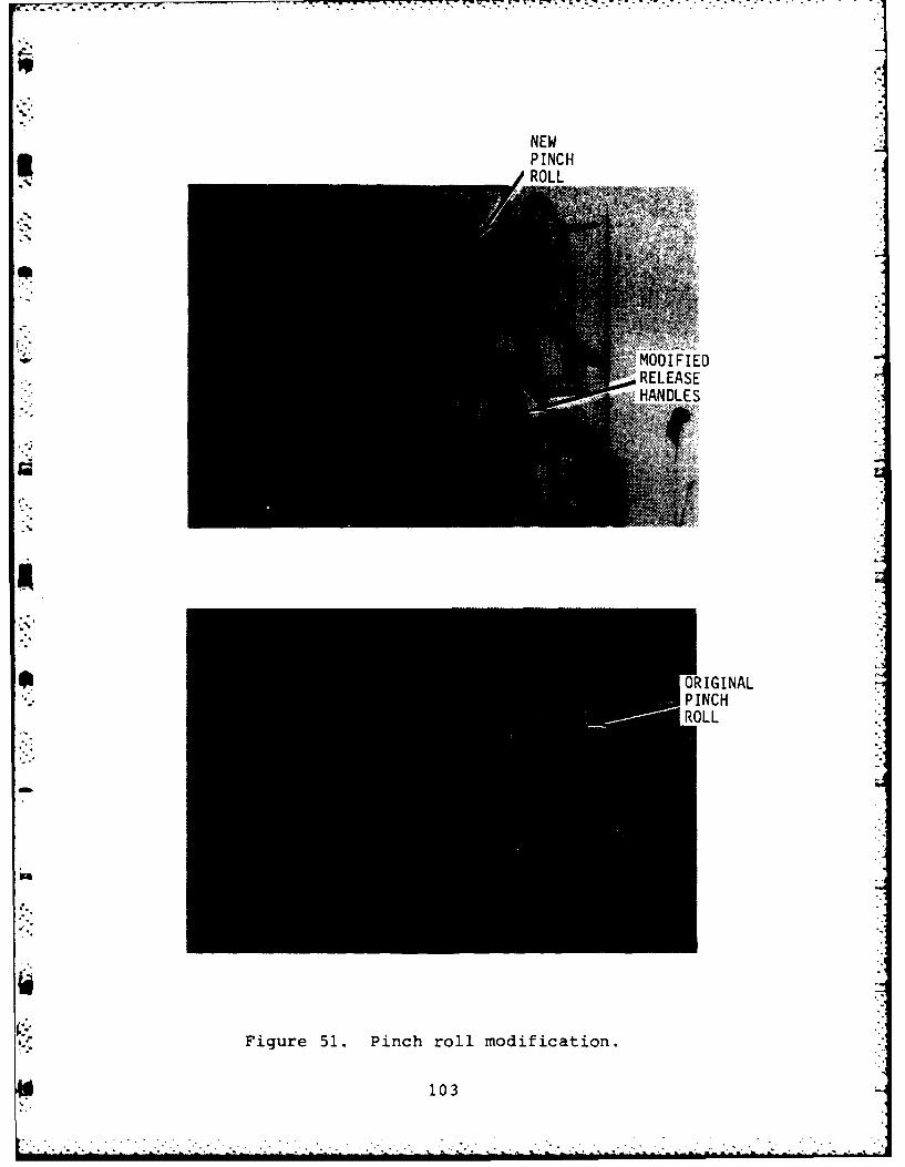
To improve system performance, two of the reels were re-
worked to widen the slot width to 12 in. and the index rolls
were modified to increase the diameter of the flanges from 11 to
13 in. and also increase the distange between flanges from 10.25
*" to 12 in. Pinch rolls having a softer, textured rubber surface
were installed. The new covering is 30 durometer BUNA rubber
with 3 circumferential grooves 1/4 in. wide by 1/8 in. deep cut
into the surface. At this time, the pinch roll release handles
were replaced also with heavier (3/8 in. versus 1/8 in.) handles
These modifications are shown in Figures 50 through 52.
A modified bale that is compatible with the larger index
rolls was installed with the index rolls to improve retention
of the hose on the vertical axis index roll. The bale consists
of two high molecular weight polypropelene rollers which contact
the hose near the top and bottom of the flattened hose. The
tension in the tensioning spring can be adjusted by means of a
turnbuckle. (See Figure 52).
-5 .1
Figure 50. Reel modification for additional clearance.
102
NEW5 PINCHROL
MODIFIED
REES
K Figure 51. Pinch roll modification.
103
LARGERINDEXROLL
MODIFIEDBALE
* Figure 52. Index roll bale modification.
104
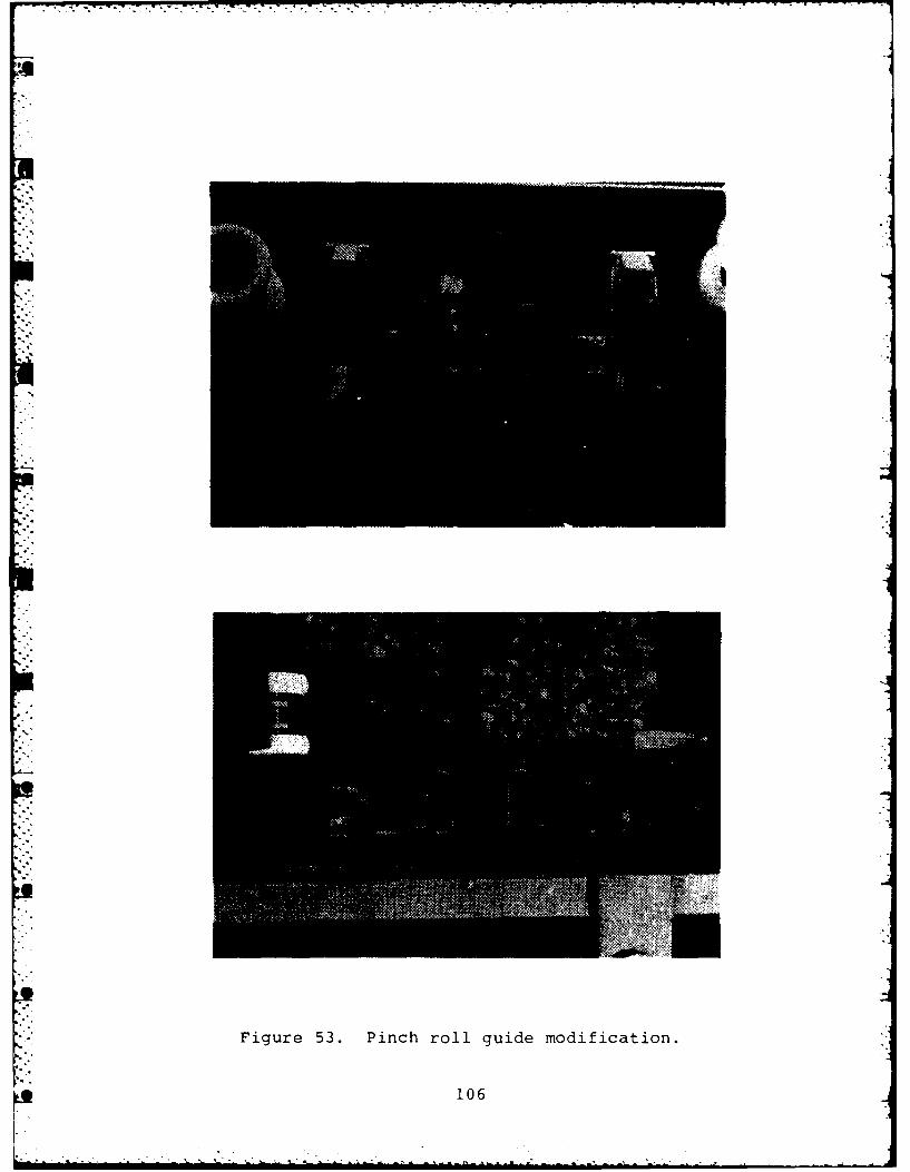
To provide additional guidance for the hose as it passed
from the index roll through the pinch rolls, two hat-section-
shaped guides were added to the pinch roll release bar as shown
,. in Figure 53. These guides eliminated the problem of the hose
riding in behind the pinch rolls and jamming.
With the above modifications, the system's performpnce was
improved. However, recovery (or pick-up) operations cc. inued
" to be smoother than deploy. When operating in the depl mode
(automatic or manual control), excessive slack was deve )ing
. between the reel and pinch rolls during turntable brak. It
had been noted that the charge pump pressure momentarily fell to
zero during turntable braking. The charge pump provides pilot
pressure for the control valve that controls the operation of
the pinch rolls and the momentary loss of pilot pressure was
- causing the pinch rolls to stop. Thus, the pinch rolls were
effectively clamping the hose at a point between the reel (which
is still paying out hose) and the ground. This resulted inexcessive slack between the reel and the vertical axis index roll.
To correct this problem, a small hydraulic accumulator was
installed in the charge pump circuit to maintain charge pressureduring turntable braking. The accumulator is rated for 2000 psi
and is operating in the system at about 200 psi. With the simplemodification, system performance during deploy operation was
dramatically improved. The accumulation is shown in Figure 54.
The screw drive for positioning the index rolls performederratically for a period of time. It was determined that a
closed center spool had inadvertantly been installed in the
manual pilot valve instead of the specified open center spool.
The correct spool was installed and the problem was corrected.
The locking pawls and the mating slots in the reel hubs
were reworked to add a positive rake to the pawls and add a
105
.- ,
* N
Figure 53. Pinch roll guide modification.
Of 106
. ,..
4 i
3 Figure 54. Accumulator installation.
chamfer to the mating surface of the reel slot to ensure proper
locking between reels. The locking pawls in the turntable were
also reworked to strengthen the tip of the pawls.
At the start of OT-I, the floodlights for night operation
were modified to improve lighting in the area of the pinch rolls.
The floodlight on the inboard, foward corner of the engine
*enclosure was removed and two portable, clamp-mounted lights were
added. The selected light is a fog light type with a narrow,
* flat beam and worked out very well in OT-1.
The voice communication system appeared to be malfunctioning
after a lost microphone was replaced by APG personnel. Upon
further investigation, it was determined that the replacement
microphone had an impedance of 30Q instead of the required 160V
resulting in a substantial loss of output. The correct micro-
phone was installed, correcting the problem.
i107
The HUSCO clutch that engages/disengages the air compressor
failed and was replaced. Because the clutch had obviously over-
heated, the hydraulic syste- was modified slightly to provide a
continuous flow of hydraulic fluid through the clutch housing
for cooling as shown in Figure 55. The clutch failure is attri-
buted to initial start-up problems at Foster-Miller that were
not recognized at the time.
Running the air compressor for extended periods of time in
high ambient temperatures resulted in overheating of the diesel
engine and, consequently, automatic shutdown of the engine. The
problem is due to the restricted air flow through the engine
enclosure. With the additional heat load of the air compressor,
the air flow is inadequate. The expedient solution for the pro-
totype HRA was to remove the front top and rear lower engine
* enclosure panels to improve cooling air flow. Sound measure-
ments were taken with the panels removed with the following
results:
a. At operator's station, system stationary, 86 dBA
diesel at 1200 RPM
b. At operator's station, diesel at 1200 RPM, 87 dBA
deploying and recovering hose
Heating protectors were provided and DT-l/OT-1 continued.
A number of displacement pigs were tried with the system
for purging the hoseline of liquid (water was used in testing).
Of the four (4) types of pigs shown in Figure 56, only the
12 in. long 6-1/2 in. diam urethane foam pig worked satisfactorily.
The four types of pigs are discussed in the following
paragraphs:
108
;2 2
I
ii
Figure 55. Clutch cooling modification.
109
%* '
J.4
Figure 56. Displacement pigs.
110
a. Bullet-shaped urethane foam. The evacuation kit as
received from Durodyne (Figure 57) contained bullet-
shaped urethane foam pigs. A semi-rigid plastic disk
was bonded to the base of the pigs. In use, the plastic
disk had to be deformed to insert the pig into the
hose adapter fitting. When compressed air was intro-
duced behind the pig, the pig moved only a few inches
and stopped. The semi-rigid disk apparently deformed
and allowed the air to flow past the pig. The semi-
rigid disk was removed and the pig tried again without
success.
-.' b. F.H. Maloney - Inflatable Sphere. A so-called
"inflatable" rubber sphere was then purchased from
F.H. Maloney Co. The ball proved to be virtually
rigid and could not be manually inserted into the
adapter fitting. These balls are widely used commeri-
I cally but in rigid pipe-not in hose. They are
"inflated" by pumping liquid into the hollow core.
Figure 57. Evacuation kit.
, iii
C. F.H. Maloney then provided a sample pig consisting of
multiple rubber disks mounted to a common shaft as
shown in Figure 56. While the concept appears reason-
able, the disks are much too stiff and the pig could
not be manually inserted into the adapter.
d. Pneumatically inflated ball - In an effort to determine-, if a pneumatically inflated sphere would work, a child's
soccer ball was tried. The under inflated soccer ball
worked very well indeed. The soccer ball was inflated
to about 1.0 psi and had an outside diameter of 6.5 in.
The use of a rugged (heavy walled) pneumatically Ainflated sphere may prove to be the preferred pig for
the system as discussed in Section 9.
e. Urethane Foam Cylinders - Cylindrical urethane foam
pigs were received from Durodyne to replace the bullet
shaped pigs. The new pigs were 12 in. long and 6.5 in.
in diameter and did not have semi-rigid endplates.
These pigs performed quite well and were used through-
out the DT-l/OT-l tests.
The procedure for purging and evacuating the hose was modi-
fied somewhat as a result of DT-1 testing. It became obviousthat the pig inlet fitting was not required and that the pig
could be pushed through multiple lengths of hose without diffi-
culty. After inserting the pig into the adapter fitting, as
shown in Figure 58, the coupling and end plug are re-installedand compressed air is introduced by simply connecting the air
line to the same quick disconnect fitting used for the air
ejector. An airhose adapter consisting of a double ended nipple
is used between the female quick disconnect on the air hose and
the female quick disconnect on the end plug.
112
* -.
Figure 58. Inserting pig into adapter fitting
During DT-1/OT-1, Foster-Miller personnel replaced the
Sfollowing failed components.
a. P-Q amplifier coil
b. Linear potentiometer
C. Solenoid control valve
d. Voice communication system microphone
e. Turntable bearing seals
f. Air compressor clutch.
113
- 7
9. HOSELINE DEVELOPMENT
The lightweight, 6 in. diam collapsible hose for the
Petroleum Hoseline System was developed by Durodyne Inc. ofTucson, Arizona under subcontract to Foster-Miller.
These candidate hoseline constructions were considered:
a) Braided hose
b) Braided hose with longitudinal reinforcement
c) Loomed jacket construction.
The salient features of each of the candidate hoses are
summarized in the following subsections.
9.1 Braided Hose
-. a) This construction contains a light layer of nylon
reinforcement and two polyester braids. Weight can
range from approximately 2.6 to 3.25 LB/FT depending
on amount of rubber compound used.
b) Typical Test Values are as follows:
1. Actual Weight - 2.75 lb/ft
2. Tube Thickness - .060 lb/ft
3. Cover Thickness - .025 lb/ft
4. Wall Thickness - .0280 lb/ft average
5. Outside Diameter - 6.56 lb/ft average
6. .65% elongation at 125 psig
7. 2.3% swell at 125 psig
8. 5% elongation at 250 psig
9. 9.5% swell at 250 psig
c) The braided hose meets all performance requirements
of specification.114
9.2 Braided Hose with Longitudinal Reinforcement ]a) Basically the same as previously mentioned braided
construction except longitudinal polyester tire cord
will be added.
b) Typical test values are as follows:
1) Outside diameter - 6.65 in. minimum possible
2) Burst pressure - 650 psig
3) 1% elongation at 150 psig
4) 2.86% diameter change at 150 psig
5) 3.97% elongation at 300 psig
6) 7.43% diameter change at 300 psig
c) This hoseline candidate is not as flexible and light-
weight as the previously mentioned braided hose. Even
with the addition of tire cord reinforcement, hose
does not meet length change requirement at 300 psig
proof pressure. This hose has excellent dimensional
stability at 150 psig (working pressure) and will with-
stand end loading to approximately 6,000 lb with very
little neckdown (approximately 4%).
9.3 Loomed Jacket Construction
This is a polyester/Kelvar jacketed hose similar to a fire
hose, but with a cover. Most loomed jacket constructions produce
*poor dimensional stability and a high degree of twist. There are
many processing problems involved in looming Kevlar yarn. Some
. work has been done on loomed jacket construction for Ft. Belvoir
Development Contract with no success. One advantage, if processing
*problems (loom) could be overcome, long length, would pose no
extreme production problems in our system.
115
.i . . * .
9.4 Hoseline Selection and Production Techniques
The braided 2.75 lb/ft hose was selected for the PHS system.
,. The Advancing Manual Technique was selected by Durodyne as the
production technique based on experimental results using produc-
tion equipment for braiding and nonstandard equipment for curing.
. Durodyne was able to produce good hose by this method, encounter-
ing no major problems that could not be resolved. Although the
" hose delivered for this program consisted of 50 ft lengths
spliced together, the same manufacturing techniques could be
used on 300 to 500 ft lengths.
9.5 Hose Assembly Fabrication and Assembly
Durodyne designed and fabricated a modified clamp ring
coupling suitable for use with grooved end pipe coupling with
MIL-C-10387. This coupling has a smooth constant outside
diameter that nests neatlyAn the coupling pocket in the reel
hub. A standard VictaulicQY style 77 gasket is used with the
clamp ring.
A total of eight (8) 500 ft hoseline assembles including
adapter fittings, clamp ring couplings, gaskets and end plugs
were delivered under this program. Five of the hoselineassemblys were put on reels and used throughout DT-I/OT-1
without failure.
116
10. CONCLUSIONS AND RECOMMENDATIONSU
The ability of the prototype Hoseline Reel Assembly to deploy
and pick up lightweight 6 in. collapsible hoseline without damage
at vehicle speeds up to 6 mi/hr was demonstrated with many dif-
ferent operators operating under automatic and manual control.
The ability to evacuate the hoseline and fully collapse it
to a repeatable thickness that permits 500 ft wraps on the reel
using the onboard air compressor and air ejector assembly was
successfully demonstrated. The ability of the hoseline assembly
including the couplings, end plugs and quick disconnect fittings
to retain a vacuum over an extended period of time was also
* demonstrated.
Functional pig geometry and physical characteristics were
Ridentified and the ability to purge multiple lengths of hose atone time was demonstrated.
Based on the results of testing and training exercises atU* Foster-Miller and the subsequent DT-l/OT-l testing it is concluded
that the Hoseline Reel Assembly is a viable design concept for
" deploying hose and, more importantly, rapidly recovering hose
" and storing it in such a manner that it is ready for immediate
redeployment. By storing the hose on a powered reel, 1800 folds
that are required in the existing flaking box hoseline systems
are eliminated and hoseline life will be improved. The labor--intensive repacking process is also eliminated.
Although the prototype HRA worked reasonably well, a number
of candidate areas for modification or redesign were identified.
117
As originally designed and built, the reel slot widths and
the index rolls were too small to ensure that the hose would reel
and unreel smoothly without grabbing or spilling off the rollers.
The reel slot widths and index rolls and other elements that
* guide the hose from the reel to ground should be re-examined
and resized to allow for such things as reel rim deformation
* and ensure that adequate clearances exist at all pointF. In
DT-1, the reel slots and index rolls were made oversized inten-
- tionally to facilitate further investigation for operating
these parameters.
The hydraulic system should be modified to incorporate a
larger pump for the pinch rolls to replace the cam-shaft-driven
pump. A larger pump could be belt driven or driven off a
multiple output gear box. This change would eliminate the
interaction between the primary (turntable) hydraulic circuit and
the pinch rolls and simply the hydraulic circuit as well as the
electrical circuit.
To reduce weight, it is recommended that a lightweight diesel
- such as the Deutz F2L511 be considered to replace the GMC 3-53
diesel. Also, the availability of a smaller, lighter air compres-
sor should be investigated. If practicable, the air compressor
* should be located at about the same level as the diesel engine
to lower the vertical center of gravity.
With a smaller diesel and air compressor, the engine enclos-
sure could also be made smaller. In any event, it is recommended
that the engine enclosure be made of aluminum and that the air
flow passages be redesigned to eliminate line of sight sound
paths and eliminate the perforated metal plates that now restrict
* air flow unnecessarily.
11
~118
To further reduce weight, consideration should be givenJ
to using a lighter hose and preferably a hose with fewer splices.
It is recommended that the automatic control system be
* retained but that the dancer roll/linear potentiometer assembly
be redesigned to provide a larger stroke with a higher spring
* rate and to replace the oil-filled wire around the potentiometer
with a DC DVDT. Consideration should also be given to incor-
* porating a surge loop perheaps similar to the concepts shown
perhaps in Figure 59.
The pinch roll release mechanism should be strengthened,
* particularly the manual release levers. Improved guides should
also be provided to prevent jamming of the hose behind the
pinch rollers.
In conclusion, several of the recommended changes would
reduce the vertical profiles, the weight, and improve the utility
of the PHS system. A smaller air-cooled diesel engine will allow
it and a smaller air compressor to be deck-mounted, lowering the
center of gravity and reducing the size of the enclosures.
The center of gravity and profile would also be lowered
by using a lighter hose with fewer splices. It has recently come
*to our attention that at least one manufacturer has developed a
light (1 lb/ft) hose capable of meeting Petroleum Hoseline System
* requirements. Use of this kind of hose would dramatically reduce
reel diameter, height, and weight, and provide for a generally
lighter and more compact HRA.
A lighter frame and deck with readily adjustable bed
clamps would reduce weight and add mounting versatility. The
* HRA could then be mounted on a variety of dedicated or undicated
SD trailers, as well as trucks.
5 119
Figure 59. Concept for adding surge loop.
The hydraulic systera for the next generation H-RA will be
manifolded as much as possible, with all components panel mounted
in readily accessible locations.
12C
U
APPENDIX A
W INSTALLING AND OPERATING THEPETROLEUM HOSELINE SYSTEM
* The Petroleum Hoseline System, comprised in part of the
Hoseline Reel Assembly (HRA) and a number of reels of 6-in.
petroleum hose, enters the theater of operations as a group of
Milvan containers. To demonstrate the level of effort needed to
operate the system, the steps of activating and using the system
to lay hose will be enumerated. Skill levels beyond those out-
lined in the letter of agreement for developing the system are
- not needed.
-,. A.1 Activating the Petroleum Hoseline System
To activate the Petroleum Hoseline System:
1. Secure a 5-ton military truck M813A2 with drop-side
- cargo bed. Secure adequate transportation for the
hose as well.U
2. Remove the drop-sides spare tire and tailgate in the
*motor pool.
3. Open the Milvan containing the Hoseline Reel Assembly
and remove the blocking and bracing.
4. Pull the HRA from the milvan using the rear tiedown
points at the base of the frame.
5. Locate the truck tiedown kit packed with the HRA.
Break it open and check the contents against the
parts list in the operating manual.
121
6. Using a forklift or crane, place the HRA on the M813A2
truck. The proper position on the truck is forward
against the front panel and offset to the right approx-
imately 8 in. as needed to get the tiedown rods of the
tiedown clamps to clear the bed sides. Secure the
tiedown clamps.
7. Using the information shown in Figure 60 and the
operating manual, perform the daily maintenance checks
on the HRA. Swing the index roll assembly outboard
if need be to add diesel fuel. No fuel will be
shipped in the unit. Prime the engine fuel system as
described in the operating manual.
8. With the engine enclosure doors open, and someone
'" watching the engine gauges, start the diesel from the
operator's station. Know where the emergency manua.
engine shutdown is! Run the engine until the water
temperature gauge needle starts to move. Shut the
diesel down.
9. Using the operating manual as a guide, swing the index
rolls into position for laying a hose. Pull the pinch
rolls out from their storage position and lock in the
operate position. Swing the loading platform out
above the pinch rolls.
10. Start the engine and use the manual controls on the
right of the operator's console to test the turn-
table's rotation, the pinch roll's rotation, and the
air compressor's function. From the loading platform,
test the turntable's free-wheeling and the index
roll's vertical movement. Depress the reel lock foot
pedal to be sure the pawls on the turntable work.
122
4IJ
-j 0
LA (3)
V))
CD M
a 4JV) w CAm -j I
cc 0 0
C-
=A~ I x ;c
W- U- ;ZA -
u.A -j -o
W- IJ
. ~ ~ C --I __ _ __ _ __
~OLALJ J L.-c
La .- LA123
11. Unpack the communications system hardware. Test the
horn and the voice circuit.
12. Button up the engine enclosure and secure the service
platform for travel.
13. Move the index rolls and the pinch rolls to their
storage positions; close the hose loading platform.
The HRA is now ready for service.
A.2 Loading a Reel on the HRA
To load a reel on the HRA:
1. Open a Milvan containing hose and pull out the first
stack of three dual reels.
2. Prepare to lift the top reel off the stack. A single
lift point is provided in the center of the reel.
3. Locate the reel separation handle in one end of the
rectangular hole. Pull on it to separate the top
reel. Lift the reel with the crane or forklift while
pulling.
4. Set the one dual reel aside.
5. Lift the remaining two dual reels and move them to
the HRA.
6. Lower the reels onto the turntable; they will lock
in place.
7. The HRA is now loaded.
124
8. Pull the second reel stack out of the milvan.
9. Separate the top dual reel following step three again.
10. Place this reel above the single reel fronm the first
* stack. Line up the rectangular slot and lower it into
contact. The reels will latch together.
11. Lift the two dual reels and place them on their
transportation. Do the same with the two dual reels
remaining. Each dual reel with two 500 ft hoseline
assemblies weighs 3550 lb. Therefore, up to five
dual reels can be transported over the highway in a
5 ton truck.
A.3 Laying a Hose
5 To lay a hose:
1. Load a reel as detailed in subsection A.2.
* 2. Drive the truck to the site with the HRA in its
storage condition.
3. Perform the daily maintenance checks.
4. Deploy the index rolls, the pinch rolls and the hose
loading platform.
5. Activate the release latch to open the pinch rolls.
6. Start the engine.
7. Freewheel the turntable with the safety gate on the
access ladder to the hose loading platform.
125
8. Starting with the upper most hose, release the secur-
ing strap holding the hose coupling to the reel.
Remove and stow the strap.
9. With the index rolls adjusted to a comfortable height,
feed the hose over the rolls and down through the
pinch rolls. Be sure that the hose is twisted clock-
wise as viewed from the operator's station looking
forward.
10. On the first hose, if at all practical, squeeze or
fold the end of the hose back on itself and tie it off
to prevent air infiltration into the hose at it is
being laid.
11. Place hose end near the pump, pipe, or existing hose.
12. Close the pinch rolls.
13. Raise the index rolls so that the hose feeds straight
to the first roll.
14. Close the safety gate after leaving the hose loading
platform.
15. Move the main control switch on the operator's console
to AUTOMATIC DEPLOY.
16. Depress the AUTOMATIC START switch.
17. Check to see that the pinch rolls tension the hose
properly.
18. Tell the truck driver to proceed in low gear along
the planned route.
126
19. Monitor the hose payout and stop the truck driver as
*the end of the hose comes up.
20. Hit the STOP switch after the truck stops.
21. Open the pinch rolls.
22. Freewheel the reel and feed the end of the hose to
the ground.
23. Feed a second hose through the HRA rolls and close the
pinch rolls. Tighten the hose on the truck and deploy
the second hose.
24. Repeat procedure for deploying additional lengths of
hose.
25. Connect ail hose ends to pump, pipe, existing hose or
tank.
26. Take the leftover parts: two plugs, one seal, and
one clamp ring. Join them together and store them.
A.4 Recovering a Hose
A.4.1 How to Evacuate and Collapse the Hose (see Figure 61)
To evacuate and collapse the hose:
1. Pinch the near end of the hose with a clamp
(Figure 62).
2. Partially pinch the end of the last hose with a clamp.
127
< >4
Fi I IL u IL LI~~i LU II
0- 40ux-
L(U
0 z w
-
w z zaZLLJ z. '-4(A, z _zo
. -J 0u.LL I- -D
UJ CL a4
D z:(i LUi
a.,
1285-
CLAMPING SCREW
Figure 62. Portable hose clamp.
129
9 7 Y
3. Remove the coupling from the near end of the hose,
insert the evacuation pig and reinstall the coupling
with an end plug.
4. Select COMPRESSED AIR on the HRA.
5. Connect air line to the plug end quick disconnect using
the double ended nipple and turn air supply on to push
the pig forward.
6. When the pig reaches the end of the hose (that is,
when it is captured by the ?artial clamp), secure the
pig by another clamp and then remove the air line.
Vent the air pressure in the petroleum hoseline.
7. Break all hose couplings and install end plugs at
both ends of each hose assembly. (See Figure 52)
8. Attach the ejector assembly to the near end of each
hose in succession (Figure 63).
9. Turn air on, and evacuate the hose of air until the
vacuum gauge reads 15 in. of mercury.
10. Remove the air line and ejection assembly.
The hose is now evacuated and collapsed and ready for
recovery.
A.4.2 How to Recover the Hose
To recover the hose:
1. Turn the selector switch of the control panel to -
MANUAL and have the pinch rolls open.
130
- ."-
. . .o.
SE
PLGVCUMGUE
VALV
Figure 63. Ejector assembly.
131
2. Position the index rolls to the lower reel slot level.
3. Rotate the reel to gain access to the coupling in the
hub.
4. Pass the end of the hose to the operator on the deck.
5. Place the end of the hose into the pocket and position
the hose in the rolls.
6. Close the pinch rolls.
7. Use the manual (electric) joystick to operate the reel
to take up any hose slack.
8. Select AUTOMATIC PICK-UP on the control panel and push
the "START" button.
9. Signal the truck driver to advance forward. As the
truck moves, the hose will be recovered automatically.
10. Watch out for the yellow band on the hose, and, when
it appears on the ground directly below the operator'sstation, signal the driver to stop.
11. Turn mode selector switch to MANUAL, and open the
pinch rolls.
12. Manually recover the remaining few feet of hose by
operating the joystick control.
13. Attach the ratchet to the end of the hose, and tie it
securely to the rim of the reel.
Proceed as outlined above to pick up any additional hoses.
132
APPENDIX B
TRAINING COURSE OUTLINE
FOR THE
PETROLEUM HOSELINE SYSTEM
Prepared by:
Foster-Miller, Inc350 S6-(ond Aveniw.,
Waltham, MA 0225-
Contract No. DAAK7O-80-C-0216
April 1982
133
SECTION I - PREFACE
A. Course: Operation and Maintenance of the Petroleum Hoseline
System Hoseline Reel Assembly
B. Purpose: To provide MERADCOM, TRADOC, TSARCOM and TECOMpersonnel with the skills and knowledge requiredto operate and maintain the Hoseline Reel Assemblyin support of DT1/OTl testing.
C. Length: 2 weeks; 10 May 1982 through 21 May 1982
D. Training Location: Foster-Miller, Inc.350 Second AvenueWaltham, MA
134
SECTION II - SUMMARY
Course- Operation and Maintenance of the Petroleum Hoseline System Hoseline
Reel Assembly
* Hours - 80
Subject: Hours Annex Page
A. Academic Subjects
Introduction 1.0 A* Elements of the Petroleum Hoseline System (PHS) 2.0 B
Operation of the Hoseline Reel Assembly (HRA) 20.0 CMaintenance of the HRA 34.0 DShipping, Storing and Installing the HRA 4.0 E
Subtotal 61.0
* B. Non-academic Subjects
Inprocessing 8.0Outprocessing 8.0Open Time 3.0
Subtotal 19.0
Total 80.0
C. Recapitulation
1. Security Classification:
Top Secret Restricted Data 0Top Secret 0Secret Restricted Data 0Secret 0Confidential 0Unrestricted 80
Nomenclature and Functions of the-HRA 2.5General Tasks and Duties of Operatorand Crew 1.5
Operating the HRA 16.0
Annex Total 20.0
Maintenance of the HRA D
Preventive Maintenance Checks and Services 8.0Corrective Maintenance 18.0Perform Maintenance 8.0
Annex Total 34.0
Shipping, Storing and Installing the HRA E
Installing the HRA 2.0Preparation for Storage 2.0 4
Annex Total 4.0
136
(2
SECTION IV - ANNEXES
ANNEX A - Introduction
Hours - 1.0
Purpose - To acquaint the student to the need for the Petroleum Hoseline-System, particularly the Hoseline Reel Assembly; to introduce the
technical manuals; to expose the student to the Hoseline ReelAssembly; and, to familiarize the student with the training facility.
• . . A-I - U.S. Army Petroleum Requirements and Methods of Delivery
Hours: 0.3
Objective: Establish the need for the Petroleum Hoseline System.
*. A-2 - Technical Manuals
Hours: 0.2
Purpose: To introduce and familiarize student with the technicalmanuals which will be the primary text for the course.
A-3 Facility and Hardware Tour
Hours: 0.5
Objective: To expose the student to the Hoseline Reel Assembly hardwarefor the purpose of associating subsequent classroom instruc-
I tion with the physical hardware.
U137
SECTION IV - ANNEXES (Continued)
ANNEX B - Elements of the Petroleum Hoseline System (PHS)
Purpose - To provide the student with a knowledge of the nomenclature, function,performance capability and physical characteristics of the followingmajor elements of the PHS:
B-1 - Pump
Hours: 0.1
Objective: To provide the student with a knowledge of the pump's
function, physical characteristics and performancecapability.
B-2 - Hose
Hours: 0.3
Objective: To provide the student with a knowledge of the hcseline'sphysical characteristics and performance capability.
B-3 - Hoseline Repair Kit
Hours: 0.2
Objective: To provide the student with a knowledge of the componentparts of the hoseline repair kit, their use, application,and physical characteristics.
B-4 - Displacement and Evaluation Kit
Hours: 0.4
Objective: To provide the student with a knowledge of the componentsof the displacement and evacuation kit, their function andphysical characteristics.
B-5 - Hoseline Reel Assembly (HRA)
Hours: 1.0
Objective: To provide the student with a knowledge of the HRA function,physical characteristics and performance capabilities.
Reference TM-5-3835-218-14, Chapter 1, Section II.
138
L)
* SECTION IV -ANNEXES (Continued)
* . ANNEX C - Operation of the Hoseline Reel Assembly (HRA)
-Purpose - 1) To provide the student with a knowledge of the major sub-assemblies of the HRA, their function, location, performanceand physical characteristics.
-P 2) To define the general duties of the operator and crew.
3) To teach the student how to operate the HRA.
* C-1 Nomenclature and Functions of the HR.A
Hours: 2.5
Objective: To provide the student with a knowledge of the nomenclature,function, location, and characteristics of the followingsubassemblies: frame; turntable and turntable drive; reel;engine enclosure; pinch roll assembly; index roll assembly;control station; communication system.
Reference TM 5-3835-218-14, Chapter 1, Sections II and III.
* C-2 - General Tasks and Duties of Operator and Crew
UHours: 1.5
objective: To define the general tasks assigned to the vehicle driver,the HRA operator, and the ground crew.
C-3 -Operating the HRA
*Hours: 16.0
*objective: To teach the student how to operate the HRA under normaland unusual conditions. Several hours of student opera-tion of the HRA will be provided.
* Reference TM 5-3835-218-14, Chapter 2, Sections I, III, and IV.
139
SECTION IV -ANNEXES (Continued)
ANNEX D -Maintenance of the HRA
Purpose -To provide the student with a knowledge of the preventive and correc-tive maintenance procedures required to support operation of theHRA.
D-1 - Preventive Maintenance Checks and Services
Hours: 8.0
objective: To teach the student the preventive maintenance proceduresrequired at the operator and direct support level, includingthe frequency at which service is to be done. To allow thestudent to practice preventive maintenance procedures onthe HRA.
Reference TM 5-3835-218-14, Chapter 2, Section II; Chapter 3, Sections I and III.
D-2 -Corrective Maintenance
Hours: 18.0
objective: To instruct the students in the troubleshooting proceduresand corrective maintenance procedures required to supportoperation of the electrical systems and hydromechanicalsystems of the HRA. Troubleshooting techniques and pro-cedures will be emphasized. To allow the student to performselected corrective maintenance procedures on the HP.A.
Reference TM. 5-3835-218-14, Chapter 3, Sections IV and V.
140
SECTION IV - ANNEXES (Continued)
BANNEX E - Shipping, Storing and Installing the HRA
Purpose - To provide the student with a knowledge of the procedures forinstalling the HRA on the truck bed and preparing the unit forshipping and storage.
E-1 - Installing the HRA
Hours: 2.0
Objective: To teach the student what service to perform upon receipt,how to install the HRA on the vehicle bed with emphasis onsafety procedures and the preliminary servicing and adjust-ment procedures.
Reference TM 5-3835-218-14, Chapter 3, Section VI.
E-2 - Preparation for Storage
Hours: 2.0
Objective: To provide the student with a knowledge of the proceduresfor preparing the HRA for:
a. Administrative stordgeb. Intermediate storagec. Long-term storage.