Page 1
KSC-PLN-5406 OCTOBER 22, 2013
Revision: Basic
METRIC/INCH-POUND
National Aeronautics and Space Administration
John F. Kennedy Space Center
KSC FORM 16-12 (REV. 6/95) PREVIOUS EDITIONS ARE OBSOLETE (CG 11/95)
KDP-F-5407 BASIC DOCUMENT1/
DESIGN AND DEVELOPMENT ELECTRICAL, ELECTRONIC, ELECTROMECHANICAL (EEE) PARTS
PLAN
ENGINEERING AND TECHNOLOGY DIRECTORATE
EAR 99 The information contained in the document is technical in content, but not technical data as defined by the
International Traffic in Arms Regulations (ITAR) or the Export Administration Regulations (EAR), and therefore is EAR 99 NLR, no export license required. [General Prohibition Six (Embargo) applies to all items subject to the EAR, (i.e.,
items on the CCL and within EAR 99 NLR). You may not make an export or re-export contrary to the provisions of part 746 (Embargos and Other Special Controls) of the EAR and 22 CFR part 126.1 of the ITAR].
Reference EDDR #1315836 -- NASA KSC Export Control Office -- 321-867-9209
.
RELEASED - Printed documents may be obsolete; validate prior to use.
Page 2
RELEASED - Printed documents may be obsolete; validate prior to use.
Page 3
KSC-PLN-5406 OCTOBER 22, 2013
Revision Basic
JOHN F. KENNEDY SPACE CENTER, NASA
DESIGN AND DEVELOPMENT ELECTRICAL, ELECTRONIC, ELECTROMECHANICAL (EEE) PARTS
PLAN
Prepared by: _____________________________________ Erik C. Denson Chief Engineer, Electrical Design and Development, KSC Engineering and Technology Directorate
Approved by: _____________________________________ Pepper E. Phillips Director, KSC Engineering and Technology Directorate
RELEASED - Printed documents may be obsolete; validate prior to use.
Page 4
KSC-PLN-5406
October 22, 2013
Revision Basic
iv Document1
CONTENTS
1. SCOPE ...............................................................................................................1
2. APPLICABLE DOCUMENTS .........................................................................2
3. ROLES AND RESPONSIBILITY ....................................................................4 3.1 The Program/Project ..........................................................................................4 3.2 The EEE Parts Control Panel .............................................................................4
4. APPLICABILITY ..............................................................................................5
5. EEE PART TYPES ............................................................................................6
6. PART SELECTION AND GRADE ..................................................................7 6.1 Parts Grade Comparisons ...................................................................................7 6.2 Parts Selection ..................................................................................................11 6.2.1 GSE and GSS Part Selection............................................................................11 6.2.2 Grade 1 Parts for Criticality 1 Part Applications .............................................11 6.2.3 Grade 2 Parts for Criticalities 1R, 2, 2R, 3, and 1S Part Applications ............12 6.2.4 Grade 3 Parts for Criticality 3 Applications ....................................................12 6.2.5 Grade 4 Parts for Criticality 2 and 3 Applications ...........................................13 6.3 Qualified Manufacturer Lists (QMLs) .............................................................13
7. COTS AND NONSTANDARD PARTS .........................................................14 7.1 Evaluation ........................................................................................................14 7.2 Testing and Qualification .................................................................................15 7.3 Vendor Selection ..............................................................................................15 7.4 Procurement .....................................................................................................15
8. AS-BUILT, AS-DESIGNED PARTS AND MATERIAL LIST .....................16
9. IONIZING RADIATION ................................................................................16
10. SCREENING ...................................................................................................19
11. QUALIFICATION ..........................................................................................20 11.1 Qualification Requirements .............................................................................20 11.1.1 Component/Part Level .....................................................................................20
11.1.2 Assembly Level ...............................................................................................21 11.2 Additional Qualification Types ........................................................................21 11.2.1 History..............................................................................................................21 11.2.2 Similarity..........................................................................................................21 11.2.3 Existing Test Data ............................................................................................21
RELEASED - Printed documents may be obsolete; validate prior to use.
Page 5
KSC-PLN-5406
October 22, 2013
Revision Basic
Document1 v
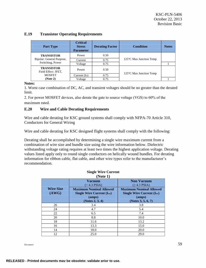
12. DERATING .....................................................................................................21
13. TRACEABILITY ............................................................................................22 13.1 Traceability Overview .....................................................................................22 13.2 Traceability Requirements ...............................................................................22 13.3 Part Tracking ....................................................................................................23 13.4 Traceability Records ........................................................................................23
14. COUNTERFEIT PART PREVENTION .........................................................23 14.1 OCM, OEM, and Franchised Distributors .......................................................24 14.2 Nonfranchised Distributors ..............................................................................24
14.3 Procurement Requirements ..............................................................................24 14.4 Detected Counterfeit Parts ...............................................................................25 14.5 Part Inspection and Testing ..............................................................................25
15. GOVERNMENT-INDUSTRY DATA EXCHANGE PROGRAM (GIDEP) .26
16. PART OBSOLESCENCE ...............................................................................26 16.1 Part Selection ...................................................................................................27 16.2 Obsolescence Avoidance .................................................................................27 16.2.1 Obsolescence Analysis.....................................................................................27 16.2.2 Manufacturing Status .......................................................................................27 16.2.3 Projected Availability ......................................................................................28 16.3 Part Procurement ..............................................................................................28
16.3.1 Lifetime Buy and Bridge Buy ..........................................................................28 16.3.2 Planned Technology Refresh ...........................................................................28 16.4 Obsolete Part Alternatives ...............................................................................29 16.5 Part Obsolescence Tracking .............................................................................30
17. EEE PARTS AND QUALIFICATION DATABASES ..................................30
18. LIMITED-LIFE PARTS/ITEMS LIST ...........................................................31
19. AVOIDING HAZARDS ..................................................................................31
20. HANDLING AND STORAGE .......................................................................32
21. VERIFICATION..............................................................................................32
APPENDIX A. DEFINITIONS .................................................................................................35
APPENDIX B. PROJECT AND PAYLOAD CLASSISFICATIONS .....................................41
APPENDIX C. EEE PARTS APPLICABILITY MATRIX .....................................................43
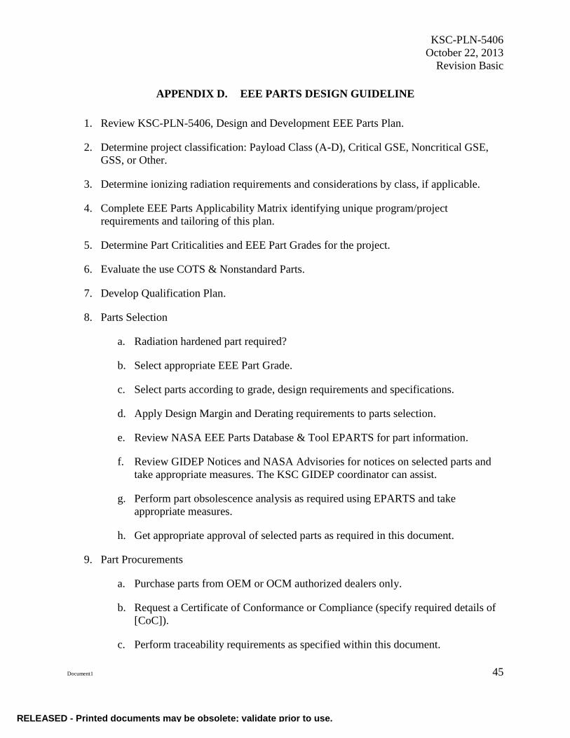
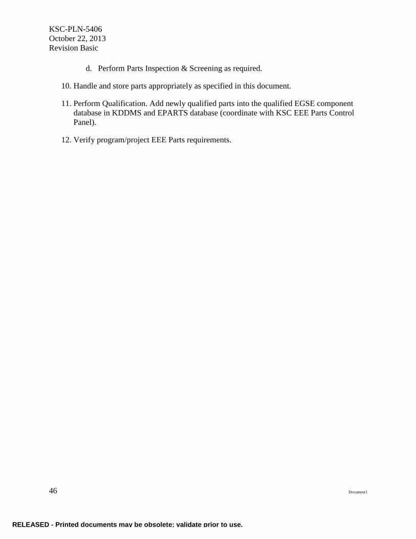
APPENDIX D. EEE PARTS DESIGN GUIDELINE...............................................................45
RELEASED - Printed documents may be obsolete; validate prior to use.
Page 6
KSC-PLN-5406
October 22, 2013
Revision Basic
vi Document1
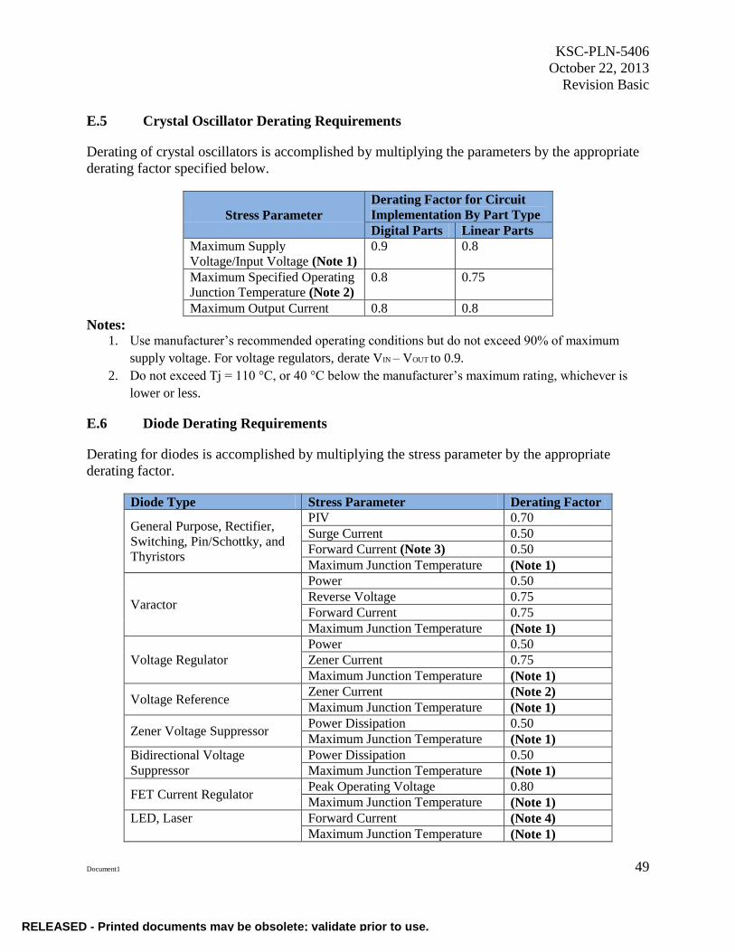
APPENDIX E. EEE PARTS DERATING REQUIREMENTS ...............................................47
APPENDIX F. HAZARD AND SAFETY RISKS ...................................................................61
APPENDIX G. WEBPAGES AND HYPERLINK REFERENCES ........................................65
APPENDIX H. EXAMPLE NONSTANDARD PART APPROVAL REQUEST
(NSPAR) FORM ..............................................................................................67
TABLES
Table 1. EEE Part Types ..................................................................................................7 Table 2. EEE Parts Grade Description .............................................................................8 Table 3. Comparison of EE Part Grade Requirements ....................................................9 Table 4. Radiation Considerations by Class ..................................................................18 Table 5. EEE Part Manufacturing Status .......................................................................27 Table 6. EEE Part Availability Projection .....................................................................28 Table 7. Obsolescence Mitigations ................................................................................29 Table 8. Obsolescence Mitigation Risk Matrix .............................................................30
FIGURE
Figure 1. EEE Parts Requirement Flow ............................................................................2
.
RELEASED - Printed documents may be obsolete; validate prior to use.
Page 7
KSC-PLN-5406
October 22, 2013
Revision Basic
Document1 vii
ABBREVIATIONS, ACRONYMS, AND SYMBOLS
ACORD Association for Cooperative Operations Research and Development
AEC Automotive Electronics Council
AoA analysis of alternatives
CAGE Commercial And Government Entity
CDR Critical Design Review
CoC Certificate of Compliance
COTS commercial-off-the-shelf
DD displacement damage
DMSMS Diminishing Manufacturing Sources and Material Shortages
DSCC Defense Supply Center, Columbus
EEE Electrical, Electronic, and Electromechanical
EGSE Electrical Ground Support Equipment
ELDRS Enhanced Low Dose Rate Sensitivity
EMI Electromagnetic Interference
EOL end of life
EPARTS Electronic Parts Applications Reporting and TrackingSystem
EPCP EEE Parts Control Panel
ERAI Electronic Resellers Association International
ERD environmental requirements document
ESD electrostatic discharge
GIDEP Government-Industry Data Exchange Program
GSE Ground Support Equipment
GSS Ground Support Systems
JANS Joint Army Navy Class S
KDDMS Kennedy Design Data Management System
KNPR Kennedy NASA Procedural Requirements
KSC John F. Kennedy Space Center
LDC lot date code
LET linear energy transfer
RELEASED - Printed documents may be obsolete; validate prior to use.
Page 8
KSC-PLN-5406
October 22, 2013
Revision Basic
viii Document1
MSFC Marshall Space Flight Center
NASA National Aeronautics and Space Administration
NE KSC Engineering and Technology Directorate
NPD NASA Policy Directive
NPSL NASA Parts Selection List
NSPAR Nonstandard Part Approval Requests
OCM original component manufacturer
OEM original equipment manufacturer
OIG Office of the Inspector General
PDN product discontinuance notice
PEM plastic encapsulated microcircuits
PDR Preliminary Design Review
PMN Program Model Number
PR Purchase or Procurement Request
QML Qualified Manufacturing Line
QPL Qualified Parts List
RDM radiation design margin
RSAR Reliability and Safety Assessment Report
SAA Safety Assurance Analysis
SCD Source Control Drawing
SEB single event burnout
SEE single event effects
SEFI single event functional interrupts
SEGB single event gate rupture
SEL single event latchup
SET single event transient
SOW Statement of Work
TID total ionizing dose
VICD Vendor Item Control Drawing
RELEASED - Printed documents may be obsolete; validate prior to use.
Page 9
KSC-PLN-5406
October 22, 2013
Revision Basic
Document1 1
DESIGN AND DEVELOPMENT ELECTRICAL, ELECTRONIC,
ELECTROMECHANICAL (EEE) PARTS PLAN
1. SCOPE
This plan establishes guidelines for the implementation of requirements for electrical, electronic,
and electromechanical (EEE) parts selection, management, and control for flight projects, flight
experiments, and Ground Systems (GS) that include Ground Support Equipment (GSE) and
Ground Support Systems (GSS) for Kennedy Space Center (KSC) design and development
projects. The implementation of an EEE parts plan greatly increases the predicated reliability of
electronic components, assemblies, and subsystems, thus increasing the likelihood of mission
success.
As specified in this document, requirements and guidelines differ between flight projects and
ground systems. EEE parts include components, assemblies and subassemblies. This plan is
tailorable, and is intended to meet the requirements specified in NPD 8730.2, NASA Parts
Policy, KNPR 8720.2, KSC Reliability and Maintainability Procedural Requirements, Chapter 3,
EEE & Mechanical Parts, Material and Processes, and KSC-DE-512, Facility Systems, Ground
Support Systems and Ground Support Equipment General Design Guidelines. The EEE parts
requirements flow is shown in Figure 1.The parts requirements and the guidelines described in
this document are to be selectively applied based on mission needs, spaceflight project and
payload classification, GSE system criticality, and program/project requirements. System needs
and requirements should be evaluated to determine the extent to which each requirement and
guideline should be applied and documented in the project plan. The tailored plan shall be
approved by the KSC EEE Parts Control Panel (EPCP).
The implementation of an EEE parts plan greatly increases the predicated reliability of electronic
components, assemblies and subsystems, thus increasing the likelihood of mission success.
RELEASED - Printed documents may be obsolete; validate prior to use.
Page 10
KSC-PLN-5406
October 22, 2013
Revision Basic
2 Document1
* Project EEE Parts Plans may be tailored from KSC-PLN-5406, EEE Parts Plan, and may be as simple as completing the applicability matrix with specific program/project requirements.
Figure 1. EEE Parts Requirement Flow
2. APPLICABLE DOCUMENTS
The following documents form a part of this document to the extent specified herein. When this
document is used for procurement, including solicitations, or is added to an existing contract, the
specific revision levels, amendments, and approval dates of said documents shall be specified in
an attachment to the Solicitation/Statement of Work/Contract.
Government
GSFC-EEE-INST-002 EEE-INST-002: Instructions for EEE Parts
Selection, Screening, Qualification, and Derating
GSFC-311-QPLD-017 Goddard Spaceflight Center Qualified Parts List
KDP-KSC-P-2102 Kennedy Documented Procedure: GIDEP
Evaluation-Disposition
KDP-KSC-P-2103 Kennedy Documented Procedure: GIDEP Initiation
& Publication
KNPR 8700.2 KSC System Safety and Reliability Analysis
Methodology Procedural Requirements
RELEASED - Printed documents may be obsolete; validate prior to use.
Page 11
KSC-PLN-5406
October 22, 2013
Revision Basic
Document1 3
KNPR 8720.2 KSC Reliability and Maintainability Procedural
Requirements
KSC-NE-10074 Electrical Ground Support Equipment Qualification
Test Plan
KSC-STD-164 Standard for Environmental Test methods for
Ground Support Equipment
KSC-STD-G-0003B Standard for Qualification of Launch Support and
Facility Components
MSFC-STD-3012 Electrical, Electronic, And Electromechanical (EEE)
Parts Management And Control Requirements For
MSFC Space Flight Hardware
MSFC-STD-3619 MSFC Counterfeit Electrical, Electronic, And
Electromechanical Parts Avoidance, Detection,
Mitigation, And Disposition Requirements For
Space Flight And Critical Ground Support Hardware
NPD 8730.2 NASA Policy Directive: NASA Parts Policy
NPR 7120.5 NASA Space Flight Program and Project
Management Requirements
NPR-8705.4 NASA Policy Requirements: Risk Classification for
NASA Payloads.
Military
MIL-PRF-27 Performance Specification Transformers And
Inductors (Audio, Power, And High-Power Pulse),
General Specification For
MIL-PRF-38534 Performance Specification Hybrid Microcircuits,
General Specification For
MIL-PRF-39010 Performance Specification Coil, Radio Frequency,
Fixed, Molded, Established Reliability And
Nonestablished Reliability, General Specification
For
MIL-PRF-83446 Performance Specification Coils, Radio-Frequency,
Chip, Fixed Or Variable, General Specification For
RELEASED - Printed documents may be obsolete; validate prior to use.
Page 12
KSC-PLN-5406
October 22, 2013
Revision Basic
4 Document1
MIL-STD-883 Test Method Standard Microcircuits
MIL-T-55631 Transformers; Intermediate Frequency, Radio
Frequency, and Discriminator, General Specification
for
Commercial
ANSI/ESD S20.20 Development of an Electrostatic Discharge Control
Program for: Protection of Electrical and Electronic
Parts, Assemblies and Equipment (Excluding
Electrically Initiated Explosive Devices)
AS9003 Inspection and Test Quality Systems
AS9100 Quality Systems – Aerospace - Model for Quality
Assurance in Design, Development, Production,
Installation and Servicing.
AS9120 Quality Management Systems – Aerospace
Requirements for Stocklist Distributors.
ISO 9001 International Organization for Standards, Quality
Management System Standards.
3. ROLES AND RESPONSIBILITY
3.1 The Program/Project
It is the ultimate responsibility of the program/project to implement the requirements and
guidelines specified in this document to meet program/project needs and requirements. The
project may develop a tailored EEE Parts Plan which may include only the EEE Parts
Applicability Matrix identifying specific program/project requirements and the EEE Parts Design
Checklist described in the appendices of this document and verify compliance.
3.2 The EEE Parts Control Panel
The roles and responsibilities of the KSC EEE Parts Control Panel (EPCP) are defined in the
EPCP charter.
KSC EPCP responsibilities include:
a. establish KSC EEE parts policy compliance to NPDs and KNPRs,
RELEASED - Printed documents may be obsolete; validate prior to use.
Page 13
KSC-PLN-5406
October 22, 2013
Revision Basic
Document1 5
b. review and approve new parts, materials, and processes as required,
c. approve program/project-tailored EEE Parts Plans as required,
d. approve waivers and exceptions to part-selection requirements specified in this
document that do not violate NPD or KNPR requirements,
e. review all proposed commercial-off-the shelf (COTS) hardware for criticality 1 or
criticality 2, high-risk, significant-risk or safety risk applications for acceptability
and define any additional screening, qualification, inspections, or modifications
required before approval for use on the program/project,
f. approve nonstandard part requests.
g. approve part procurements for nonfranchised distributors,
h. initiate investigative action on suspect counterfeit parts and other
noncompliances,
i. provide alert notifications to NASA, Government-Industry Data Exchange
Program (GIDEP), Electronic Resellers Association International (ERAI), and the
Office of the Inspector General (OIG) for counterfeit parts and other
noncompliances as required,
j. review and approve submissions of newly qualified EEE parts into the Electronic
Parts Applications Reporting and Tracking System (EPARTS) database,
k. review and approve submission of newly identified obsolete and end-of-life
(EOL) EEE parts to the EPARTS obsolescence tool,
l. approve using a part that has an expected life less than its design life, and
m. for spaceflight projects, approve project-specified screening requirements that are
less stringent than EEE-INST-002
4. APPLICABILITY
NPD 8730.2, The NASA Parts Policy Directive, applies to flight hardware, critical GSE, and
critical ground test systems used in Category 1 and Category 2 projects as defined by
NPR 7120.5D, NASA Space Flight Program and Project Management Requirements, and/or
Class A, B, or C payloads as defined by NPR 8705.4, Risk Classification for NASA Payloads,
Appendix A (also specified in Appendix B of this document). Although agency part
requirements are specified for the classifications above, there are sound engineering EEE parts
practices that should be applied throughout NASA projects. This plan applies to KSC-designed
and -developed flight projects and experiments (space and aeronautical), Ground Systems that
include GSE and GSS. As specified in this document, requirements and guidelines differ
RELEASED - Printed documents may be obsolete; validate prior to use.
Page 14
KSC-PLN-5406
October 22, 2013
Revision Basic
6 Document1
between flight projects and ground systems. The implementation of the parts requirements and
guidelines described in this document are tailorable, and should be selectively applied based on
mission requirements, spaceflight project and payload classification, GSE system criticality, and
program/project requirements. Appendix C shows the EEE parts applicability matrix for payload
classes A-D, critical and noncritical GSE, GSS, and other systems. As indicated in the Appendix
C matrix, depending on the category, specific project requirements may be added or removed.
EEE part grade selection shall be based upon spaceflight project and payload classification, GSE
system criticality, and program/project requirements. A risk assessment shall be performed by
the program/project to determine the use of EEE parts.
COTS equipment is used extensively in the design of GS and some low-cost spaceflight projects.
It can be cost prohibitive to apply EEE parts requirements to COTS equipment. Implementation
of requirements and guidelines for the use of COTS EEE parts and equipment in flight projects
and GS are defined within this document.
5. EEE PART TYPES
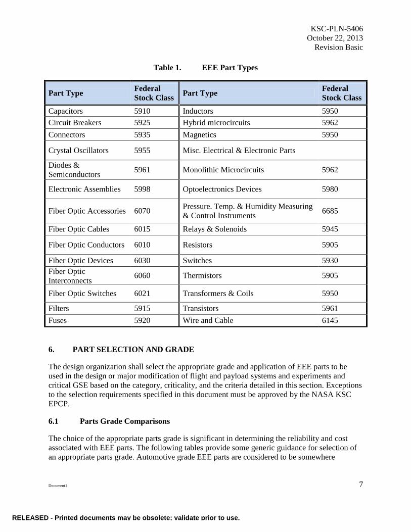
This document applies to the EEE part types listed in Table 1. Assemblies and subassemblies,
including COTS assemblies that contain component part types in Table 1, are considered EEE
parts.
The EEE parts requirements also apply to EEE parts in sensor and transducer assemblies and
solenoids where basic sensing/transducer pieces are packaged in an assembly with other
electrical part types such as wire, connector, resistor, etc.
For flight projects, parts approved for use with waivers/deviations, electronic parts and materials
should be manufactured and processed to applicable guidelines referenced in MIL-HDBK-454,
General Guidelines for Electronic Equipment, or MIL-HDBK-1547, Electronic Parts, Materials,
and Processes for Space and Launch Vehicles.
Part types that do not fall into one of the categories listed in Table 1 shall be reviewed on a case-
by-case basis using the closest NASA, Defense Supply Center Columbus (DSCC), or
government-controlled specification as a baseline. The review shall ensure that part meets the
reliability requirements of its intended application and covers the selection, screening,
qualification, and applicable derating. In the event a suitable government baseline specification
does not exist, the project shall approach the NASA KSC EPCP.
RELEASED - Printed documents may be obsolete; validate prior to use.
Page 15
KSC-PLN-5406
October 22, 2013
Revision Basic
Document1 7
Table 1. EEE Part Types
Part Type Federal
Stock Class Part Type
Federal
Stock Class
Capacitors 5910 Inductors 5950
Circuit Breakers 5925 Hybrid microcircuits 5962
Connectors 5935 Magnetics 5950
Crystal Oscillators 5955 Misc. Electrical & Electronic Parts
Diodes &
Semiconductors 5961 Monolithic Microcircuits 5962
Electronic Assemblies 5998 Optoelectronics Devices 5980
Fiber Optic Accessories 6070 Pressure. Temp. & Humidity Measuring
& Control Instruments 6685
Fiber Optic Cables 6015 Relays & Solenoids 5945
Fiber Optic Conductors 6010 Resistors 5905
Fiber Optic Devices 6030 Switches 5930
Fiber Optic
Interconnects 6060 Thermistors 5905
Fiber Optic Switches 6021 Transformers & Coils 5950
Filters 5915 Transistors 5961
Fuses 5920 Wire and Cable 6145
6. PART SELECTION AND GRADE
The design organization shall select the appropriate grade and application of EEE parts to be
used in the design or major modification of flight and payload systems and experiments and
critical GSE based on the category, criticality, and the criteria detailed in this section. Exceptions
to the selection requirements specified in this document must be approved by the NASA KSC
EPCP.
6.1 Parts Grade Comparisons
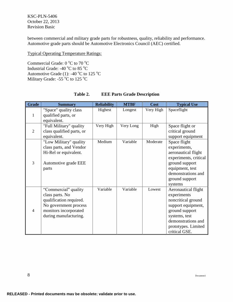
The choice of the appropriate parts grade is significant in determining the reliability and cost
associated with EEE parts. The following tables provide some generic guidance for selection of
an appropriate parts grade. Automotive grade EEE parts are considered to be somewhere
RELEASED - Printed documents may be obsolete; validate prior to use.
Page 16
KSC-PLN-5406
October 22, 2013
Revision Basic
8 Document1
between commercial and military grade parts for robustness, quality, reliability and performance.
Automotive grade parts should be Automotive Electronics Council (AEC) certified.
Typical Operating Temperature Ratings:
Commercial Grade: 0 oC to 70
oC
Industrial Grade: -40 oC to 85
oC
Automotive Grade (1): -40 oC to 125
oC
Military Grade: -55 oC to 125
oC
Table 2. EEE Parts Grade Description
Grade Summary Reliability MTBF Cost Typical Use
1
"Space" quality class
qualified parts, or
equivalent.
Highest Longest Very High Spaceflight
2
"Full Military" quality
class qualified parts, or
equivalent.
Very High Very Long High Space flight or
critical ground
support equipment
3
"Low Military" quality
class parts, and Vendor
Hi-Rel or equivalent.
Automotive grade EEE
parts
Medium Variable Moderate Space flight
experiments,
aeronautical flight
experiments, critical
ground support
equipment, test
demonstrations and
ground support
systems
4
“Commercial" quality
class parts. No
qualification required.
No government process
monitors incorporated
during manufacturing.
Variable Variable Lowest Aeronautical flight
experiments
noncritical ground
support equipment,
ground support
systems, test
demonstrations and
prototypes. Limited
critical GSE.
RELEASED - Printed documents may be obsolete; validate prior to use.
Page 17
KSC-PLN-5406
October 22, 2013
Revision Basic
Document1 9
Table 3. Comparison of EE Part Grade Requirements
Item Grade 1 Grade 2 Grade 3 Grade 4
Typical
Minimum
Quality Class for
First Choice.
Microcircuit:
Class S or V
Hybrid
Microcircuit:
Class K
Discrete
Semiconductor:
JANS (Joint
Army-Navy,
Class S)
Cap. Or Resistor:
Failure Rate
Level (FRL) S, R
or C
Other: Various
Microcircuit:
Class B or Q
Hybrid
Microcircuit:
Class H
Discrete
Semiconductor:
JANTXV
Cap. Or Resistor:
FRL R, P, or B
Other: Various
Microcircuit:
Class M, N, T, or
/883
Hybrid: Class G,
D, or E
Discrete
Semiconductor:
JANTX
Cap. or Resistor:
P or B, and Other
Other: Various
Vendor Hi-Rel
Automotive
grade EEE parts
Commercial
(Often is PEM)
PIND & X-Ray Intrinsic to Class
Accomplished by
additional
screening
Not required No
Typical
Minimum Piece
Part
Qualification
Military or NASA or equivalent
As required per
program/project
qualification
plans.
Not specified
Radiation
Hardness
Assurance
(RHA) by
Analysis and/or
Test
Yes, When Specified Not required
Procurement
Limited to
Qualified Source
Yes
Required for
flight systems
and experiments,
GSE, and GSS.
Recommended
for others
Lot Quality
Conformance
Inspection
Required
Yes
Yes, but less
stringent than
Grade 1
requirements
Yes, but much
less stringent
than Grade 2
requirements
No
RELEASED - Printed documents may be obsolete; validate prior to use.
Page 18
KSC-PLN-5406
October 22, 2013
Revision Basic
10 Document1
Item Grade 1 Grade 2 Grade 3 Grade 4
Screening 100% required
100%
recommended,
not as stringent
as Grade 1
Limited Limited if used
in critical GSE
Hazard
Avoidance Yes
Specification and
Control
Drawings
Military, NASA,
or Industry
Standard, or
Project prepared
Control Drawing
(e.g. SCD,
VICD)
Mostly Military,
NASA, or
Industry
Standards, or
Project prepared
Control Drawing,
but also limited
use of Vendor
Specifications.
Vendor
Specifications,
Industry and
Organizational
Standards, and
Military or
NASA
Standards.
Optional
Derating Yes Yes if used in
critical GSE
Nonstandard Part
Approval
Request
For a part not
listed as a
standard Grade 1
part which may
be determined
acceptable to use
in a Grade 1
application.
Yes if used in
critical GSE
For a part not
listed as a
standard Grade 3
part which may
be determined
acceptable to use
in a Grade 3
application.
Yes if used in
critical GSE
As-Designed
EEE Parts List Yes
Traceability By Lot and Serial Number as a Minimum
Required for
flight systems
and experiments,
GSE, and GSS.
Recommended
for others.
Part Selection
Preferences
Specified
Yes As determined
by design team
Substitutions
Restricted Yes
Substitutions
allowed based on
parts selection
criteria
No
As-Built EEE
Parts List Yes
RELEASED - Printed documents may be obsolete; validate prior to use.
Page 19
KSC-PLN-5406
October 22, 2013
Revision Basic
Document1 11
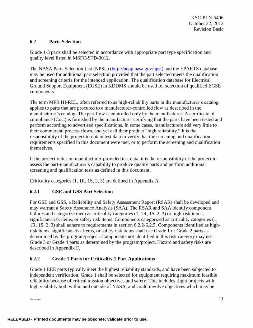
6.2 Parts Selection
Grade 1-3 parts shall be selected in accordance with appropriate part type specification and
quality level listed in MSFC-STD-3012.
The NASA Parts Selection List (NPSL) (http://nepp.nasa.gov/npsl) and the EPARTS database
may be used for additional part selection provided that the part selected meets the qualification
and screening criteria for the intended application. The qualification database for Electrical
Ground Support Equipment (EGSE) in KDDMS should be used for selection of qualified EGSE
components.
The term MFR HI-REL, often referred to as high-reliability parts in the manufacturer’s catalog,
applies to parts that are procured to a manufacturer-controlled flow as described in the
manufacturer’s catalog. The part flow is controlled only by the manufacturer. A certificate of
compliance (CoC) is furnished by the manufacturer certifying that the parts have been tested and
perform according to advertised specifications. In some cases, manufacturers add very little to
their commercial process flows, and yet call their product “high reliability.” It is the
responsibility of the project to obtain test data to verify that the screening and qualification
requirements specified in this document were met, or to perform the screening and qualification
themselves.
If the project relies on manufacturer-provided test data, it is the responsibility of the project to
assess the part-manufacturer’s capability to produce quality parts and perform additional
screening and qualification tests as defined in this document.
Criticality categories (1, 1R, 1S, 2, 3) are defined in Appendix A.
6.2.1 GSE and GSS Part Selection
For GSE and GSS, a Reliability and Safety Assessment Report (RSAR) shall be developed and
may warrant a Safety Assurance Analysis (SAA). The RSAR and SAA identify component
failures and categorize them as criticality categories (1, 1R, 1S, 2, 3) or high-risk items,
significant-risk items, or safety risk items. Components categorized as criticality categories (1,
1R, 1S, 2, 3) shall adhere to requirements in section 6.2.2-6.2.5. Components identified as high-
risk items, significant-risk items, or safety risk items shall use Grade 1 or Grade 2 parts as
determined by the program/project. Components not identified in this risk category may use
Grade 3 or Grade 4 parts as determined by the program/project. Hazard and safety risks are
described in Appendix F.
6.2.2 Grade 1 Parts for Criticality 1 Part Applications
Grade 1 EEE parts typically meet the highest reliability standards, and have been subjected to
independent verification. Grade 1 shall be selected for equipment requiring maximum feasible
reliability because of critical mission objectives and safety. This includes flight projects with
high visibility both within and outside of NASA, and could involve objectives which may be
RELEASED - Printed documents may be obsolete; validate prior to use.
Page 20
KSC-PLN-5406
October 22, 2013
Revision Basic
12 Document1
difficult to repeat in another mission. Flight missions of 5 years or longer may also require
Grade 1 parts. Repair during the mission is not a practical or desirable option. The parts selection
of Grade 1 parts shall conform to the requirements contained in MSFC-STD-3012, Table V.
Parts selection should be accomplished in the order indicated. A lower-ranked selection should
not be used if a higher-ranked part selection can be obtained.
6.2.3 Grade 2 Parts for Criticalities 1R, 2, 2R, 3, and 1S Part Applications
For hardware items used in criticality 1R#, 2R, 2, 3, and 1S applications, except as noted in
sections 6.2.4 and 6.2.5 for Criticality 3 applications, a minimum of grade 2 parts should be used
in the design, modification, and fabrication of flight equipment and critical GSE. Maximum use
should be made of standard parts that have a history of high reliability.
The parts selection shall conform to the requirements contained in MSFC-STD-3012,
Table VI. Parts selection shall be accomplished in the order indicated. A lower ranked selection
should not be used if a higher-ranked selection can be obtained. A nonstandard grade 2 part may
be used in accordance with MSFC-STD-3012 when a standard part is not available. Commercial-
quality-assurance-level parts shall not be used in these applications without EPCP approval. The
objective shall be to minimize part types, utilize standard part types to the maximum extent
possible, and ensure that appropriate minimum quality levels are maintained.
Grade 2 EEE parts typically meet rigorous (but not the highest) industry reliability standards, and
have been subjected to independent verification. Grade 2 should be selected for equipment that
requires high reliability, but for which a low risk of failure can be tolerated to meet cost
constraints. Flight missions of 1 to 5 years duration may use grade 2 parts. The mission may be
multiple or single purpose, with a repeat mission possible. Repair during the mission may be
practical. Functional or block redundancy for all primary objectives is desirable but single-string
design may be acceptable. The application usually is spaceflight equipment or critical GSE
components categorized as high-risk items, significant-risk items, or safety risk items.
6.2.4 Grade 3 Parts for Criticality 3 Applications
For Criticality 3 applications, the program/project may approve the use of grade 3 parts in the
design, modification, and fabrication of the flight equipment and critical GSE. Grade 3 parts
shall be qualified for its operational environment.
The parts selection of Grade 3 parts shall conform to the requirements contained in MSFC-STD-
3012, Table VII. Parts selection should be accomplished in the order indicated. A lower-ranked
selection should not be used if a higher-ranked selection can be obtained. A nonstandard grade 3
part may be used in accordance with MSFC-STD-3012 when a standard part is not available. The
objective is to minimize part types, utilize standard part types to the maximum extent possible,
and ensure that appropriate minimum acceptable quality levels are maintained.
Grade 3 EEE parts typically meet standards for high reliability, but there may be significant
exceptions and the parts may not have been independently verified. Grade 3 parts should be
RELEASED - Printed documents may be obsolete; validate prior to use.
Page 21
KSC-PLN-5406
October 22, 2013
Revision Basic
Document1 13
selected for equipment where high reliability is desired, but is not mandatory. The flight missions
are typically for a single-purpose or routine mission with repeat missions possible. Flight mission
duration may be less than 1 year. Repair during the mission would not necessarily be considered
worthwhile. Single-string design would normally be acceptable. For critical GSE, redundancy is
usually implemented. The application is usually spaceflight and aeronautical experiments or
critical GSE and GSS components NOT categorized as high-risk items, significant-risk items, or
safety risk items.
Grade 3 parts include “industrial” rated commercial parts. Grade 3 parts shall be qualified for
their environment per program/project requirements.
6.2.5 Grade 4 Parts for Criticality 2 and 3 Applications
For Criticality 2 and 3 applications, the EPCP may approve the use of grade 4 parts in the design,
modification, and fabrication of the flight equipment and critical GSE components not
categorized as high-risk, significant-risk, or safety risk items. The parts selection of Grade 4
parts should conform to the requirements contained in MSFC-STD-3012 Table VIII. A Grade 4
part shall be qualified for its operational environment.
Grade 4 EEE parts typically meet vendor standards for high reliability or commercial
marketplace reliability, but have not been independently verified. Grade 4 should be selected for
equipment where high reliability is not a primary factor, the mission is not critical, or a repeat
mission is possible. The duration of a mission would typically not be lengthy. Repair may be
very practical. Typical applications of Grade 4 parts include low-cost flight experiments, test
demonstration projects, prototypes, and some GSE and GSS. For GSE applications, redundancy
should be implemented.
6.3 Qualified Manufacturer Lists (QMLs)
Use of Qualified Manufacturer Lists (QMLs) can greatly aid in the selection and procurement of
qualified EEE parts. “QML” means a list of manufacturers who have had their products
examined and tested and who have satisfied all applicable qualification requirements for that
product according to manufacturer requirements and military specifications. To select and
procure an EEE part using a QML, a Part Identification Number (PIN) is generated for the part.
The PIN is generated using the appropriate military performance specification (MIL-PRF) or
military detail specification (MIL-DTL) for the desired federal stock class and part grade. Using
the PIN, one can query the QML for providers of that part. Purchasing parts from a QML
provides the pedigree of that part, and asserts the reliability of the part for a given usage.
Information on QML, MIL-PRF, and MIL-DTL can be found on the Defense Logistics Agency
website: http://www.landandmaritime.dla.mil/programs/qmlqpl/ .
RELEASED - Printed documents may be obsolete; validate prior to use.
Page 22
KSC-PLN-5406
October 22, 2013
Revision Basic
14 Document1
7. COTS AND NONSTANDARD PARTS
The determination of EEE part grades used in COTS equipment and assemblies is difficult to
achieve. Testing and qualification are critical to the implementation of COTS in NASA projects.
A nonstandard part is an electronic part that has not been approved for listing in GSFC-EEE-
INST-002, KSC EGSE qualified component database or in other applicable NASA-approved
parts lists; e.g., EPARTS, NPSL, or does not have a qualification plan and which fits into one of
the applicable Federal Stock Classes (i.e., 5905, 5910, 5915, 5920, 5935, 5950, 5961, 5962, or
6145). Nonstandard parts also include lower-grade parts that are used in higher-grade
applications outside the requirements specified in paragraph 6.2 of this document.
The selection, application, and testing of COTS and nonstandard parts shall be in accordance to
the following criteria:
7.1 Evaluation
Programs/projects and contractors shall evaluate systems using COTS and nonstandard
components to determine the criticality category of applications.
System concepts shall be evaluated (performance, availability, etc.) including life cycle/mission
profile (transportation and storage, operation mode and sequences, duration, etc.), and
environmental conditions (temperature extremes, humidity, shock, vibration, acoustics,
electromagnetic compatibility, and radiation).
The following conditions shall apply for the use of COTS and nonstandard parts:
a. For component criticality category 1 or 2 , high-risk items, significant-risk items, or
safety risk items, the KSC EPCP shall review all proposed COTS and nonstandard
hardware for acceptability, and shall define any additional screening, qualification,
inspections, or modifications required before approval for use on the project. A
Nonstandard Part Approval Request (NSPAR) form must be completed to use
nonstandard parts. An example NSPAR form is shown in Appendix H.
b. A reliability analysis shall be performed (typically performed by safety and reliability
engineers).
c. Designers/developers shall evaluate a redundant architecture and implement in the design
as required.
d. Designers/developers shall implement derating and adequate design margins.
e. Government Industry Data Exchange Program (GIDEP), NASA and contractor alerts,
advisories, and reports shall be reviewed for relevance to potential COTS items before
selection or use in the project or system.
RELEASED - Printed documents may be obsolete; validate prior to use.
Page 23
KSC-PLN-5406
October 22, 2013
Revision Basic
Document1 15
7.2 Testing and Qualification
An appropriate prescreening, test, and qualifications plan shall be developed based on the
environmental and mission profile requirement.
COTS and nonstandard parts shall also be tested in accordance to its operational/mission profile
environment.
Environmental tests such as acoustic, vibration, shock, radiation, pressure, thermal,
electromagnetic compatibility, and accelerated life shall be performed on COTS, when
applicable.
7.3 Vendor Selection
Authorized vendor sources shall be determined and used to prevent counterfeit parts. Original
component/equipment manufacturers have lists of authorized vendors for their products. The
supplier quality listings shall be reviewed to determine existing acceptability of any potential
vendor.
The vendor’s quality practices (audits), test data, and failure data shall be investigated. The
vendor selected shall have in place good design, workmanship, and quality control practices.
The project and design organizations purchasing COTS items shall work with vendors to
modify/upgrade parts with higher reliability parts, if necessary. COTS shall be evaluated for
lifecycle obsolescence and required logistic spares for the project life cycle.
7.4 Procurement
When parts cannot be procured to appropriate specifications, a drawing, such as a Source Control
Drawing, should be prepared by the developer to control procurement requirements. For
spaceflight projects, the drawing should include the screening and qualification requirements
specified in Tables 2 and 3 of EEE-INST-002 for the applicable part type. The drawing shall also
include performance parameters, absolute maximum ratings, dimensions, terminal descriptions,
materials, and other unique requirements.
With project approval, unique screening and qualification requirements that are not normally
performed by the manufacturer as part of their normal production practice may be placed directly
in the purchase order in lieu of preparing a developer-controlled drawing. It is the responsibility
of the project to require test data from the manufacturer in order to verify compliance.
The following documents and reports, as applicable, shall be requested as part of the purchase
request.
a. certificate of conformance or compliance (CoC)
b. test and analysis reports
RELEASED - Printed documents may be obsolete; validate prior to use.
Page 24
KSC-PLN-5406
October 22, 2013
Revision Basic
16 Document1
c. workmanship certifications
d. test and inspection compliance
e. material certifications
f. screening results
g. calibration records
8. AS-BUILT, AS-DESIGNED PARTS AND MATERIAL LIST
An as-built parts or as-designed parts and materials list for EEE parts shall be prepared and
maintained.
The as-built parts or as-designed parts and materials list shall be reviewed against GIDEP failure
experience data and NASA Parts Advisories.
The list shall include, as a minimum, the following information:
a. part number
b. part name or description
c. manufacturer name or Commercial and Governmental Entity (CAGE) number
d. quantity
e. schematic reference numbers
f. screening information
g. lot date code
h. drawing number and name of the next higher assembly where part is located
If it is a standard part, the part number shall be the military specification part number or the
procurement document number. If it is a nonstandard part, it shall include the manufacturer's part
number and the nonstandard part approval number.
9. IONIZING RADIATION
EEE parts intended for use in flight hardware shall be qualified to operate with acceptable
performance during and after exposure to the part-level radiation environment specified in the
program/project environmental requirements document (ERD).
RELEASED - Printed documents may be obsolete; validate prior to use.
Page 25
KSC-PLN-5406
October 22, 2013
Revision Basic
Document1 17
For grades 1, 2, and 3 parts, and where feasible, for grade 4 parts used in spaceflight
applications, the effects of the projected ionizing radiation on each part or assembly shall be
determined by analysis and/or test. Radiation evaluation shall address all threats appropriate for
the technology, application, and environment, including Total Ionizing Dose (TID), Enhanced
Low Dose Rate Sensitivity (ELDRS), Single Event Effects (SEE), and Displacement Damage
(DD) as defined in the project ionizing radiation control document and shall be assessed on a lot-
specific basis according to the program/project requirements.
Parts shall be selected based upon their ionizing radiation environment and immunity, life cycle,
and program/project requirements. Failure mitigation or a design margin shall be established by
the project to ensure acceptable performance in the projected radiation environment. Parameter
degradation limits shall be developed from the available test data for use in the worst-case
analysis and for use in determining acceptance requirements after radiation testing.
Allowable SEE rates shall be defined and used for reference in evaluating designs for suitability.
Parts shall be selected so that equipment meets specified performance requirements when
exposed to the SEE radiation environment. SEE includes single-event upsets, transients, latch-
ups, burnouts, gate ruptures, and snapbacks. Safety-critical circuits shall be designed so that they
will not fail because of SEE. The project shall demonstrate through testing or analysis whether
the selected parts can withstand SEE.
Table 4 provides ionizing radiation considerations by class as indicated in Appendix B and
defined by NPR 8705.4.
Low-cost spaceflight experiments and projects such as Class D payloads that do not require
radiation hardened parts should consider the following:
a. Analyze parts for radiation susceptibility, considering environment and project lifetime.
b. Identify critical parts. Use the highest grade feasible for critical parts.
c. Implement redundancy.
d. Utilize watchdog timers and software resets.
RELEASED - Printed documents may be obsolete; validate prior to use.
Page 26
KSC-PLN-5406
October 22, 2013
Revision Basic
18 Document1
Table 4. Radiation Considerations by Class
Requirement
Class A
Payload
Class B
Payload
Class C
Payload
Class D
Payload
SEL
(Single Event
Latchup)
Linear Energy
Transfer
(LET)th >75
MeV-cm2/mg
LETth >75
MeV-cm2/mg
or <10-4
events/yr
LETth >75
MeV-cm2/mg
or <10-4
events/yr
LETth >37
MeV-
cm2/mg or
<10-3
events/yr
SEGR/SEB
(Single Event
Gate Rupture /
Single Event
Burnout)
LETth >37
MeV-cm2/mg
LETth >37
MeV-cm2/mg
LETth >37
MeV-cm2/mg
LETth >37
MeV-
cm2/mg
SEU
(Single Event
Upset)
LETth >75
MeV-cm2/mg
or <1E-10 per
bit per day or
by analysis
verifying no
impact to
mission
requirements
LETth >75
MeV-cm2/mg
or < 1E-10 per
bit per day or
by analysis
verifying no
impact to
mission
requirements
LETth >37
MeV-cm2/mg
or <1E-10 per
bit per day or
by analysis
verifying no
impact to
mission
requirements
none
SEFI
(Single Event
Functional
Interrupts)
LETth >75
MeV-cm2/mg
or <10-3
events/yr
LETth >75
MeV-cm2/mg
or <10-2
events/yr
LETth >37
MeV-cm2/mg
or <10-1
events/yr
none
SET
(Single Event
Transient)
LETth >75
MeV-cm2/mg
or by analysis
verifying no
impact to
mission
requirements
LETth >75
MeV-cm2/mg
or by analysis
verifying no
impact to
mission
requirements
LETth
>37MeV-
cm2/mg or by
analysis
verifying no
impact to
mission
requirements
none
RELEASED - Printed documents may be obsolete; validate prior to use.
Page 27
KSC-PLN-5406
October 22, 2013
Revision Basic
Document1 19
Requirement
Class A
Payload
Class B
Payload
Class C
Payload
Class D
Payload
TID, ELDRS 1/ (Total
Ionizing
Radiation,
Enhanced Low
Dose Rate
Sensitivity)
Meets ERD
level w/RDM
(Radiation
Design
Margin) of 2;
Parametric
acceptance @
90%
confidence w/
99%
probability of
success
Meets ERD
level w/RDM
of 2;
Parametric
acceptance @
90%
confidence w/
99%
probability of
success
Meets ERD
level w/RDM
of 2;
Parametric
acceptance @
90%
confidence w/
99%
probability of
success
Meets ERD
level
w/RDM of
1;
Parametric
acceptance
at specified
limits
DD 1/
(Displacement
Damage)
Meets ERD
level w/ RDM
of 2; Survival
@ 90%
confidence w/
99%
probability of
success
Meets ERD
level w/ RDM
of 2; Survival
@ 90%
confidence w/
99%
probability of
success
Meets ERD
level w/ RDM
of 2; Survival
@ 90%
confidence w/
90%
probability of
success
Meets ERD
level w/
RDM of 1;
at go- no-go
Notes: 1/ Parts with spot shielding require an RDM of 3 for Class A, B, and C, and an RDM of 2 for Class D.
Spaceflight classifications are given in Appendix B.
10. SCREENING
Screening tests are intended to remove nonconforming parts (parts with random defects that are
likely to result in early failures [known as infant mortality]) from an otherwise acceptable lot and
thus increase confidence in the reliability of the parts selected for use.
For spaceflight projects and payload project class A-C, grades 1, 2, and 3 parts shall be subjected
to screening. Any required test that is already performed by the procurement specification
(military or SCD) or that is normally performed by the manufacturer need not be repeated,
however, lot specific attributes data must be submitted to show that tests were performed with
acceptable results. The project is responsible for specifying and documenting device-unique
requirements, if any. Screening shall be performed in accordance with EEE-INST-002,
Instructions for EEE Parts Selection, Screening, Qualification, and Derating. The
program/project shall determine the appropriate level of screening required based on project
classification and criticality. Project specified screening requirements that are less stringent than
EEE-INST-002 shall be approved by the KSC EEE Parts Control Panel. For other flight project
classifications, screening may be performed based on project requirements.
RELEASED - Printed documents may be obsolete; validate prior to use.
Page 28
KSC-PLN-5406
October 22, 2013
Revision Basic
20 Document1
Traditional screening of GS components is not required. Because electronics designed for KSC
GS projects will have a large number of run-time hours prior to launch, are redundant, and are
easily accessible for replacement; visual screening, along with functional and performance
testing of components and assemblies is sufficient. Functional and performance testing shall be
conducted on 100% of assemblies.
11. QUALIFICATION
11.1 Qualification Requirements
When a KSC flight project is required by spaceflight project or payload classification to use
grades 1, 2, and 3 EEE parts, these parts should be qualified at the component/part level.
Otherwise, assembly-level qualification should be performed. Specified KSC spaceflight projects
and payload project class A-C shall perform qualification per Goddard Space Flight Center
EEE-INST-002, Instructions for EEE Parts Selection, Screening, Qualification, and Derating.
For other flight project classifications, the program/project may develop a qualification plan or
tailor EEE-INST-002 and KSC-E-NE-10074 to meet program/project requirements.
For KSC GSE projects, grades 1 and 2 EEE parts shall be qualified at the component part level.
For projects using grades 3 and 4 EEE parts, assembly level qualification is sufficient.
Qualification shall be performed in accordance with KSC-STD-G-0003B, Standard for
Qualification of Launch Support and Facility Components. Qualification testing shall be in
accordance with KSC-NE-10074, Electrical Ground Support Equipment Qualification Test Plan.
Qualification methods shall be in accordance with KSC-STD-164, Standard for Environmental
Test Methods for Ground Support Equipment
Any required test that is already performed by the procurement specification (military or SCD)
need not be repeated. However, lot specific or generic attributes data, as applicable, must be
submitted to show that tests were performed with acceptable results. Qualification is generally
considered destructive and samples shall be segregated from flight parts or field-deployed
operational GSE.
11.1.1 Component/Part Level
Qualification at the component/part level shall be achieved by meeting designated military or
NASA standards component part qualification requirements or by other means as documented
for nonstandard part approval. Requirements for qualification of nonstandard parts shall be
equivalent to the requirements imposed on similar standard parts, or shall otherwise satisfactorily
demonstrate that the part has an approved margin of safety beyond the demands of the equipment
in which it will be used.
RELEASED - Printed documents may be obsolete; validate prior to use.
Page 29
KSC-PLN-5406
October 22, 2013
Revision Basic
Document1 21
11.1.2 Assembly Level
Part qualification at the assembly level shall be based upon qualification testing of the assembled
equipment. A part shall be qualified for a given application within the assembly by successful
performance during qualification testing, or by similarity to a part which has been so qualified.
11.2 Additional Qualification Types
Qualification by usage history or similarity to qualified parts is acceptable as discussed below.
11.2.1 History
A part can be considered qualified if it has been used successfully in (a) applications identical to
that proposed (heritage design) or (b) applications different from that proposed if the application,
including derating and environmental conditions, is fully documented and is more severe than
the proposed application. For spaceflight projects, the part must have been used for 2 years
minimum total operating time in orbit. The part must have been built by the same manufacturer
in the same facility, using the same materials and processes to an equivalent Source Control
Drawings (SCD). It is the program/project’s responsibility to have such evidence documented.
11.2.2 Similarity
A part can be considered qualified if it is similar to a part for which qualification test data exists,
and the test data (a) satisfies the requirements specified herein for the applicable part level, and
(b) is available and is less than 2 years old relative to the lot date code of parts. In order to be
considered similar, the part shall be made by the same manufacturer on the same manufacturing
line, or on a line with only minor differences, and these differences shall be documented and
shown to represent no increased reliability risk.
11.2.3 Existing Test Data
Parts can be qualified by existing test data that meets the requirements specified herein: (a) Lot
specific data indicates that parts have the same lot date code as the qualification samples. Lot
specific data is always acceptable in place of qualification testing when it meets the requirements
specified herein. (b) Generic data is an acceptable basis for qualification if it is less than 1 year
old relative to the lot date code of parts, and is acquired and reviewed for acceptability by the
designer/developer. The project shall also verify that the data is representative of parts, e.g., built
in the same facility using identical or similar processes.
12. DERATING
Derating guidance for flight and ground system EEE parts is provided in Appendix E. Project
derating requirements may differ based upon project life cycle, reliability, and performance
requirements. GSE is typically designed for a life expectancy of 15-20 years. Derating
calculations shall be documented in the system design analysis report.
RELEASED - Printed documents may be obsolete; validate prior to use.
Page 30
KSC-PLN-5406
October 22, 2013
Revision Basic
22 Document1
13. TRACEABILITY
13.1 Traceability Overview
Traceability and certification information shall be captured during the design process in order to
prepare for the ultimate certification process. Traceability records include the heritage and
compliance for purchased parts and material, along with design compliance with requirement
traceability, including all tests, analyses, demonstrations, and inspections accomplished to verify
the product has met the intended design. Waivers, deviations, and exceptions to any requirement
shall be substantiated, approved, and documented.
Traceability is important because it allows us to track the location and usage of parts in hardware
designs. In case of obsolescence, NASA advisory alerts, and GIDEP alerts, it is possible to
identify the parts and implement the required resolution.
13.2 Traceability Requirements
a. Identification and traceability data for all EEE parts shall be documented by
program/project or design organization.
b. Parts shall be traceable to the next level assembly and to the reference designator level.
c. As a minimum, the following information shall be documented for purchased parts:
1) Procurement request number
2) Part name and number
3) Part manufacturer’s name or CAGE code
4) Vendor or distributor information (EEE parts shall only be purchased from authorized
vendors)
5) Manufacturer’s lot date code and/or serial number
6) Logistics arrival date
7) Quantity purchased
d. A CoC shall be provided by the manufacturer when specified in the procurement request.
Although warranties provide the government with rights for repair or replacement, a CoC
provides the assurance that the material, part, component, or system is new and that tests
have proven that the item provided conforms to the purchase requirement. A CoC may
include test and analysis reports, workmanship compliance, material compliance,
calibration records, and inspection reports.
RELEASED - Printed documents may be obsolete; validate prior to use.
Page 31
KSC-PLN-5406
October 22, 2013
Revision Basic
Document1 23
13.3 Part Tracking
a. Parts shall be tracked during all phases of the project, procurement, storage (logistics),
issuance/kitting, fabrication (assembly and subassemblies), and installation.
b. Piece parts or component-level parts shall be tracked by manufacturer lot numbers.
c. Assemblies and subassemblies, including COTS (when applicable), shall be tracked by
serial number. Assemblies shall be serialized.
d. Parts shall be tracked to the assemblies in which they are used. Distributed parts shall be
tracked to assembly kit and next level assembly number.
e. A means for parent-child relationships between components, subassemblies, and
assemblies, i.e., schematic drawing number, reference designators (Ref Des), and
program model numbers (PMN), should be established and documented.
f. Maintenance, refurbishment, replacement, and repair actions shall be traced and
documented.
13.4 Traceability Records
Traceability records include the heritage and compliance for purchased parts and material.
Applicable records should include the following:
a. certificate of conformance or compliance (CoC)
b. test and analysis reports
c. workmanship certifications
d. test and inspection compliance
e. material certifications
f. screening results
g. calibration records
14. COUNTERFEIT PART PREVENTION
EEE parts shall be procured only from the original component manufacturer (OCM), original
equipment manufacturer (OEM), or their franchised (authorized) distributors.
RELEASED - Printed documents may be obsolete; validate prior to use.
Page 32
KSC-PLN-5406
October 22, 2013
Revision Basic
24 Document1
14.1 OCM, OEM, and Franchised Distributors
OCMs, OEMs, and their franchised distributors shall be required to provide CoCs and
acquisition traceability. Acquisition traceability consists of the name and location of all supply-
chain intermediaries from the part manufacturer to the direct source of the product. CoCs and
acquisition traceability requirements shall be clearly stated in the procurement purchase order. If
traceability is unknown or documentation is suspect, appropriate risk mitigation shall be used as
described in MSFC-STD-3619.
14.2 Nonfranchised Distributors
EEE parts should not be procured from nonfranchised (nonauthorized) distributors. Procurement
of parts from a nonfranchised distributor shall require approval from the KSC EEE Parts Control
Panel and utilization of these parts shall be in accordance with MSFC-STD-3619.
14.3 Procurement Requirements
To minimize the risk of procuring counterfeit product, the buyer’s procurement contract
language shall include requirements that will ensure conforming, authentic material is provided.
The seller’s responsibilities shall be plainly stated and agreed upon in Purchase Request (PR) or
a Statement of Work (SOW) and shall include the following:
a. The seller shall be capable of providing full traceability for the parts being purchased,
including names and addresses of prior sources (if any) to the buyer. Both buyer and
seller shall maintain records containing date and/or lot codes, and any serialization
associated with the purchase order and invoice.
b. The buyer shall notify the seller of all tests and inspections that the seller will be required
to perform to assure product authenticity, including development of accept/reject criteria
and qualification of test/inspection personnel.
c. The seller shall be required to comply with and/or be certified to, an appropriate quality
standard (e.g., AS9100, AS9120, ISO 9001, and AS9003) as determined by the buyer.
d. The buyer shall notify the seller that the seller may be liable for remedial costs associated
with the selling of counterfeit product. Procurement contracts shall state that the buyer is
not under obligation to return suspect or confirmed counterfeit product. The buyer may
request proof of financial responsibility, such as a product liability/completed operations
certificate of insurance (e.g., Association for Cooperative Operations Research and
Development [ACORD] Certificate of Liability Insurance) issued from the seller’s
insurance agent or broker. Limits of at least $1,000,000 per occurrence and $1,000,000
annual aggregate are common. The buyer may also request similar evidence of
professional liability and/or product recall insurance with similar limits from the seller.
RELEASED - Printed documents may be obsolete; validate prior to use.
Page 33
KSC-PLN-5406
October 22, 2013
Revision Basic
Document1 25
e. The buyer shall inform the seller of the specific time period for which their responsibility
applies. Terms and conditions between the buyer and seller shall allow for a reasonable
time period for the buyer to detect, quarantine, and confirm counterfeit or substandard
product. The buyer should perform a level of inspection or test sufficient to detect gross
or common indications of counterfeiting before the time expires.
f. The buyer shall provide the seller with clear and specific instructions concerning
deliverable documentation from the buyer. Documentation requirements, including
certificates of conformance and test/inspection data, should be included in the contract
terms and conditions.
g. The buyer shall notify the seller of potential Federal penalties associated with fraud and
falsification.
14.4 Detected Counterfeit Parts
If a suspected counterfeit part is detected, the following actions should be taken immediately:
a. Quarantine the product.
b. Notify KSC EEE Parts Control Panel of potential counterfeit parts.
c. Determine part authenticity by further inspection and communications with the OCM,
OEM, or supply source.
d. Identify the lot date code.
e. Identify the shipped field product.
f. The KSC EPCP shall initiate investigative action.
g. The KSC EPCP will address anomalous findings and technical issues brought up by
either the part supplier or test laboratory performing the part authentication procedures.
h. The KSC EPCP shall provide timely notification to GIDEP, ERAI, and the OIG.
14.5 Part Inspection and Testing
All items shall undergo receiving inspection, as soon as possible upon receipt, and not just prior
to installation or placing item(s) in service. Focus on whether the carton and packaging looks
worn or reused, if the manufacturer date and serial number on the carton matches the device.
Check all accessories and cables to ensure correct and functional.
Verify items are genuine by registering or sending serial numbers to the manufacturer to verify
item is new and the buyer is the original owner or licensee.
RELEASED - Printed documents may be obsolete; validate prior to use.
Page 34
KSC-PLN-5406
October 22, 2013
Revision Basic
26 Document1
Counterfeit part inspection and testing requires specialized tools and expertise. This will
typically be performed outside of KSC as necessary. Part inspection and testing may be
performed in accordance with MSFC-STD-3619.
15. GOVERNMENT-INDUSTRY DATA EXCHANGE PROGRAM (GIDEP)
EEE Parts shall be reviewed for applicable GIDEP Alerts, GIDEP Safe-Alerts, GIDEP Problem
Advisories, and GIDEP Agency Action Notices, collectively called “GIDEP Notices” and NASA
Advisories during part selection and procurement phases. The GIDEP evaluation-disposition
process shall be in accordance to KDP-KSC-P-2102. The designated KSC GIDEP coordinators
may assist in the alert search process.
As manufacturing defects, nonconformances, or problems are identified, a NASA Advisory or
GIDEP Notice (as appropriate for the situation) shall be generated and distributed accordingly.
GIDEP Notice or NASA Advisory initiation and publication shall be in accordance with
KDP-KSC-P-2103.
For parts affected by NASA Advisories, GIDEP Alerts, Safe-Alerts, or Problem Advisories the
following procedure should be performed.
a. Identify lot date code and location of parts.
b. Remove and quarantine the parts.
c. Notify KSC EPCP and KSC GIDEP coordinator of affected parts.
16. PART OBSOLESCENCE
Some flight projects have short product life cycles and are not exposed to high risk of being
affected by parts obsolescence. However, EEE parts should be evaluated for availability issues to
ensure life expectancy exceeds system design and production milestones. This process
guarantees selected parts are available beyond initial system design and procurable for
production. Performing a parts obsolescence assessment reduces cost, schedule, and technical
risk to hardware production for these flight projects.
Projects with extended product life cycles, such as GS, and those that plan to utilize heritage
hardware are exposed to high risk of being affected by parts obsolescence. To mitigate this risk,
EEE parts should be assessed prior to selection to ensure part availability meets or exceeds
production milestones and mission duration. In addition, parts will be monitored throughout the
system life cycle to identify and mitigate obsolescence issues before they occur. In the event a
system is retained in service beyond its original life expectancy, spare parts will be required for
repairs and maintenance operations. Obsolescence monitoring provides notification of part
discontinuance to allow projects with sufficient time to procure spares.
RELEASED - Printed documents may be obsolete; validate prior to use.
Page 35
KSC-PLN-5406
October 22, 2013
Revision Basic
Document1 27
16.1 Part Selection
Obsolete and limited-life EEE parts shall not be selected for hardware design unless approved by
the program/project and KSC EEE Parts Control Panel. EEE part availability should coincide
with project life-cycle requirements to avoid obsolescence impacts. Project As-Designed EEE
Parts Lists shall be analyzed prior to preliminary design review (PDR), critical design review
(CDR), as well as informal 30%, 45%, 60%, and 90% design reviews, to screen for potential
obsolescence issues. This process ensures obsolescence is not incorporated into hardware design
and eliminates diminishing manufacturing sources and material shortages (DMSMS) risks to
system production.
16.2 Obsolescence Avoidance
16.2.1 Obsolescence Analysis
The best way to avoid implementing obsolete and End of Life (EOL) parts into new designs is to
conduct an Obsolescence Analysis. An Obsolescence Analysis of EEE parts should be performed
by the designer during the early design stages when the engineer is selecting parts for their
design. If a sufficient amount of time has elapsed, another analysis should be done prior to
procuring the parts, as well as before fabrication. The NASA EPARTS EEE parts database tool
may be used to conduct the Obsolescence Analysis. This tool generates EEE part manufacturing
status and part availability projections. EEE parts should be monitored on a continuous basis for
manufacturer product discontinuance notification (PDN). EEE part manufacturers announce a
product as end-of-life (EOL) to notify consumers of the last buy date for part procurements.
Notification is typically provided one year in advance of the actual obsolescence date. Advanced
notification allows the project ample time to plan for product obsolescence and to budget for part
procurement. Obsolescence analysis tools such as the EPARTS EEE Parts Obsolescence tool
provide direct notification from the manufacturers to announce EOL EEE parts.
16.2.2 Manufacturing Status
A manufacturing status color code is usually assigned to each EEE part to denote the number of
current, active manufacturing sources. Table 5 lists each EEE part manufacturing status and
associated definition.
Table 5. EEE Part Manufacturing Status
EEE Part Manufacturing Status Definition
Obsolete (Red) No production sources are available.
End-of-Life (Orange) The manufacturer issued a part discontinuance notice.
Sole Source (Yellow) Only one production source is available.
Two or More Sources (Green) Two or more production sources are available.
Unknown (White)
EEE Part availability not recognized by tools and requiresmanual
research.
RELEASED - Printed documents may be obsolete; validate prior to use.
Page 36
KSC-PLN-5406
October 22, 2013
Revision Basic
28 Document1
Projected Years of Availability Obsolescence Date
Obsolete Current Date
1-2 years Current Date + 1 Year
3-4 years Current Date + 3 Years
5-7 years Current Date + 5 Years
8-10 years Current Date + 9 Years
11-15 years Current Date + 13 Years
16-18 years Current Date + 17 Years
16.2.3 Projected Availability
Each EEE part should be assigned projected years of availability and an estimated obsolescence
date. This forecasting technique, as seen in Table 6, allows projects to prepare and plan for EEE
part obsolescence issues that may occur throughout the system life cycle. Another method of
avoidance is the Lifetime or Bridge Buy, as discussed in the next section.
Table 6. EEE Part Availability Projection
16.3 Part Procurement
EEE parts shall be procured only from the OCM or their franchised (authorized) distributors. If
parts cannot be procured from authorized sources, then the risk of counterfeit parts shall be
avoided by complying with the requirements specified within this document.
16.3.1 Lifetime Buy and Bridge Buy
One method of avoiding obsolete parts is a lifetime buy or bridge buy. Early part procurement
entails procuring sufficient part quantities to sustain current and/or future production
requirements. A lifetime buy refers to procurement of sufficient quantities to sustain the life of
the program, while a bridge buy satisfies part requirements for a specific contract or timeframe.
The program/project shall determine the quantity required to sustain the project and comply with
the part availability requirements.
16.3.2 Planned Technology Refresh
Proactive resolution of EOL EEE parts reduces the risk of costly, unplanned redesigns of
hardware. Continuous monitoring of EEE part availability allows the program/project to plan for
technology insertion and redesign. The program/project should consider timeframe for planned
upgrades when selecting an obsolescence resolution. DMSMS issues that occur in conjunction
with or near a scheduled system upgrade provide optimal timing for technology refresh and
mitigation of obsolescence. Identification of known obsolescence and projection of future
obsolescence issues are used to prioritize assembly-level refresh cycles. System life cycle, parts
RELEASED - Printed documents may be obsolete; validate prior to use.
Page 37
KSC-PLN-5406
October 22, 2013
Revision Basic
Document1 29
sparing requirements, and program/project budget allocations should be considered for
obsolescence resolution and technology insertion.
16.4 Obsolete Part Alternatives
If unexpected obsolescence occurs without warning and the program/project is unable to prepare
for DMSMS impacts, an Analysis of Alternatives (AoA) shall be performed by the obsolescence
management team to identify potential obsolescence resolutions. This approach assumes no
authorized sources of supply for the original, obsolete part are available and part procurement
(lifetime buy or bridge buy) is not an option. The engineering team will perform an AoA using
the mitigation factors specified in Table 7
Table 7. Obsolescence Mitigations
Resolution Description
Existing Inventory Utilize existing and in-house inventories.
Form, Fit, Function Alternate Part Alternate part maintains compatible package
type, mounting and function as original part.
Functional Alternate Part
Alternate part maintains same function as
original part, but may require a circuit or
mounting change.
Equivalent Alternate Part Alternate part maintains similar attributes as the
original part.
New Manufacturing Source Identification of a new, approved source of
supply for the original obsolete part.
Redesign or Technology Refresh
Design-out obsolescence items via engineering
changes at system indenture levels, with the
goals of enhancing system performance and
improving reliability and maintainability.
The engineering and project management team shall evaluate each potential resolution for cost,
schedule, and technical risk. Table 8 provides typical risk levels associated with obsolescence
resolutions defined in Table 7. Risk levels may vary depending on system life-cycle phase,
program/project requirements, and mission duration. Resolution risk factors should be
incorporated with the AoA.
RELEASED - Printed documents may be obsolete; validate prior to use.
Page 38
KSC-PLN-5406
October 22, 2013
Revision Basic
30 Document1
Table 8. Obsolescence Mitigation Risk Matrix
Program/project management shall select obsolescence mitigations in accordance with project
life-cycle requirements and mission duration. Results of the AoA and resolution risk matrix
should be used as guidance for mitigation selection
16.5 Part Obsolescence Tracking
Newly identified obsolete and EOL EEE parts shall be reported to the KSC EPCP. These parts
will be entered and tracked in the EPARTS obsolescence tool.
17. EEE PARTS AND QUALIFICATION DATABASES
NASA is establishing a secured centralized database, the Electronic Parts Applications Reporting
and Tracking System (EPARTS). The database will serve as a central repository for project
specific EEE parts lists provided by the NASA centers. EPARTS will eventually serve as the
primary EEE parts repository for KSC projects. EPARTS is located at https:/eparts.nasa.gov/.
The qualification database for Electrical Ground Support Equipment (EGSE) contains a list of all
qualified EGSE components. The database will be maintained in KDDMS. Qualified
components listed in this database will also be exported into EPARTS.
EEE Parts that are candidates for submission into the EPARTS database must be approved by the
KSC EEE Parts Control Panel before submission.
The following resources may also be used for additional part selection provided the part selected
meets the qualification and screening criteria for the intended application.
Resolution Risk
Cost Schedule Technical
Existing Inventory Low Low Low
Form, Fit, Function Alternate Part Low Low Low
Functional Alternate Part Low Medium Medium
Equivalent Alternate Part Low Medium Medium
New Manufacturing Source High High Medium
Redesign or Technology Refresh High High High
RELEASED - Printed documents may be obsolete; validate prior to use.
Page 39
KSC-PLN-5406
October 22, 2013
Revision Basic
Document1 31
a. NASA Parts Selection List (NPSL) – http://nepp.nasa.gov/npsl/index.htm
b. Goddard Spaceflight Center Qualified Parts List (GSFC-311-QPLD-017) -
https://nepp.nasa.gov/index.cfm/12832
c. Goddard Spaceflight Center Parts Database (Access must be requested)-
https://partsdb.gsfc.nasa.gov/
18. LIMITED-LIFE PARTS/ITEMS LIST
Limited-life items shall be identified and managed using a limited-life items list.
The list shall present the following data elements: expected life, required life, duty cycle, and
rationale for selection. The useful life period starts with fabrication and ends with the completion
of the defined mission.
Records shall be maintained that allow evaluation of the cumulative stress (time and/or cycles)
for limited-life items, starting when useful life is initiated and indicating the program activity
that stressed the items. Refurbishment schedules and procedures shall be included.
The use of an item whose expected life is less than its mission design or project life should be
avoided or designed out. Use of these items shall be approved by the NE EEE Parts Control
Panel. GS are typically designed for a life expectancy of 15-20 years.
Provisions shall be made to periodically inspect limited life items which have been placed in
storage to verify condition and continued usability.
19. AVOIDING HAZARDS
No pure tin (or greater than 97% tin by weight), zinc, cadmium, or other metals that are subject
to the growth of metal whiskers, shall be used internally or externally, as an underplating or final
finish in the design and manufacture of the hardware, including, but not limited to, EEE parts
and their packages/terminals/leads, mounting hardware, solder lugs, electromagnetic interference
(EMI) shields, and structures. Tin shall be alloyed with a minimum of 3 percent lead (Pb) by
weight.
Lead-free tin alloy coatings or solders have not been approved for use on NASA hardware. Any
lead-free tin alloy soldering process used to manufacture the equipment must meet the program’s
requirements for reliability, mission life, parts compatibility, rework and thermal, vibration, and
shock environments. The information provided shall include data from design of experiments,
life test results, whiskering and/or tin pest susceptibility evaluation results, statistical process
control monitor data, temperature/materials compatibility analyses, and mechanical test results.
The EEE Parts Control Panel shall review and approve these data.
RELEASED - Printed documents may be obsolete; validate prior to use.
Page 40
KSC-PLN-5406
October 22, 2013
Revision Basic
32 Document1
Note that Sn96/Ag4 and Sn95/Sb5 are standard solder-attach materials used in high-temperature
soldering applications and are acceptable for those applications only.
20. HANDLING AND STORAGE
Electrostatic discharge (ESD) control plans shall be developed in accordance with
ANSI/ESD S20.20, or an approved equivalent.
Environmental conditions such as temperature, humidity, and particulate contamination shall be
identified and appropriately controlled for parts handling, packaging, and storage.
When required, parts may be stored in logistic areas with restricted access.
Parts shall be stored indicating:
a. project and point of contact
b. part name and number
c. manufacturer’s lot date code and/or serial number
d. arrival date
e. Procurement Request number
Documentation received with parts such as certificates of compliance or conformance,
warranties, test and inspection reports, material certifications, screening results and calibration
records shall be archived.
EEE parts older than 5 years from date of manufacture shall be reviewed by the responsible EEE
parts engineering activity to determine the need for rescreening and qualification. Parts stored in
conditions where moisture or ESD are not controlled shall not be used.
Suspect or counterfeit parts and parts affected by NASA Advisories, GIDEP Alerts, Problem
Advisories, or Safe-Alerts shall be quarantined from general stock and handled appropriately.
Obsolete parts shall be labeled as such.
21. VERIFICATION
The program/project shall verify that applicable requirements specified within this document and
defined in the project EEE Parts Applicability Matrix and EEE Parts Design Checklist have been
adhered to.
The as-designed EEE Parts List shall be analyzed to determine what EEE parts are used by
design.
Nonstandard Part Approval Requests (NSPAR) or equivalent data shall be analyzed to determine
the terms for acceptance and use of the applicable EEE parts.
RELEASED - Printed documents may be obsolete; validate prior to use.
Page 41
KSC-PLN-5406
October 22, 2013
Revision Basic
Document1 33
The EEE Parts Derating Analysis Report shall be analyzed to determine what derating is
achieved for the application.
The As-built EEE Parts List shall be analyzed to determine that only traceable approved EEE
parts and sources are used.
RELEASED - Printed documents may be obsolete; validate prior to use.
Page 42
RELEASED - Printed documents may be obsolete; validate prior to use.
Page 43
KSC-PLN-5406
October 22, 2013
Revision Basic
Document1 35
APPENDIX A. DEFINITIONS
Analysis of Alternatives: An analytical comparison of the operational effectiveness, cost, and
risks associated with proposed solutions to EEE parts obsolescence issues.
Audit: A systematic, independent, official, examination and verification of: records and other
objective evidence of work performed; the process; or the process requirements to determine
compliance to requirements; and to assess the effectiveness of implementation and identify
potential improvements.
Bridge Buy: The early procurement of EEE part requirements for a specific contract or
timeframe.
Certificate of Conformance (CoC): A document provided by a supplier formally declaring that
all buyer purchase order requirements have been met. The document may include information
such as manufacturer, distributor, quantity, lot batch, lot date code, inspection date, etc., and is
signed by a responsible party for the supplier.
Certificate of Conformance and Traceability (CoCT): A certificate of conformance required
by certain military specifications, which requires documented traceability from the Qualified
Parts List/Qualified Manufacturing Line (QPL/QML) manufacturer through delivery to the
Government if the material is not procured directly from the manufacturer.
Commercial Off-The-Shelf (COTS): Equipment, including hardware and associated
software/procedures, that is commercially available from the industrial inventory at the time of
purchase.
Counterfeit Part: A part whose material, performance, or characteristics are knowingly
misrepresented by a supplier in the supply chain. Examples of counterfeit parts include the
following:
a. Parts that do not contain the proper internal construction (die, manufacturer, wire
bonding, etc.) consistent with the ordered part.
b. Parts that have been used, refurbished, or reclaimed but are represented as new
product.
c. Parts that have different package style or surface plating/finish than the ordered
parts.
d. Parts that have not successfully completed the OCM’s full production and test
flow but are represented as completed product.
e. Parts sold as upscreened parts, which have not successfully completed
upscreening.
RELEASED - Printed documents may be obsolete; validate prior to use.
Page 44
KSC-PLN-5406
October 22, 2013
Revision Basic
36 Document1
f. Parts sold with modified labeling or markings intended to misrepresent the part’s
form, fit, function, or grade.
g. Parts which have been refinished, upscreened, or uprated and have been identified
as such, are not considered counterfeit.
Critical Ground Support Equipment: a system whose loss of function or improper
performance could result in serious injury, damage to flight hardware, loss of mission, or major
damage to a significant ground asset.
Critical Ground Test Systems: a system whose loss of function or improper performance could
result in serious injury, damage to the item under test, or major damage to a significant ground
asset.
Criticality Category 1: A single failure point that could result in loss of vehicle or loss of flight
or ground personnel.
Criticality Category 1R: Redundant items, which if all failed, could result in loss of the vehicle
or loss of flight or ground personnel.
Criticality Category 1S: A single failure point of the system component designed to provide
safety or protection capability against a potentially hazardous condition or event, or a single
failure point in a hazard or safety monitoring system that causes the system to fail to detect, or
operate when needed during the existence of a hazardous condition that could lead to a loss of
flight or ground personnel or vehicle.
Criticality Category 2: A single failure point that could result in loss of a critical mission
support capability.
Criticality Category 3: All others.
Note: Some programs/projects may define severity categories differently.
Derating: Derating is the reduction of electrical and thermal stresses applied to a part during
normal operation in order to decrease the degradation rate and prolong its expected life.
Diminishing Manufacturing Sources and Material Shortages: The loss or impending loss of
manufacturing or production sources or suppliers of components, end-items, and/or raw
materials.
End-of-Life: Indication that a manufacturer will no longer produce or support a particular
product after a specified discontinuance date.
Finding: A conclusion of importance based on facts established during S&MA audits, reviews,
and assessments. There are seven categories of findings for S&MA audits, reviews, and
RELEASED - Printed documents may be obsolete; validate prior to use.
Page 45
KSC-PLN-5406
October 22, 2013
Revision Basic
Document1 37
assessments: Catastrophic Noncompliance, Critical Noncompliance, Major Noncompliance,
Noncompliance, Minor Noncompliance, Observation, Commendation, and Best Practice.
Franchised Distributor: A source authorized by the original component manufacturer to
distribute its parts.
Government Agency: A contract administration office, such as, Air Force, Navy, or Defense
Contract Management Command, or another NASA Center, that has been delegated authority by
KSC, or any element of KSC, to perform contract administrative service functions.
Government-Industry Data Exchange Program (GIDEP): A cooperative effort to exchange
information essential to the research, development, design, testing, acquisition, production,
operation, and logistics among U.S. and Canadian governments and industry participants.
GIDEP seeks to reduce or eliminate expenditures of time and money. The proper utilization of
GIDEP data can materially improve the total quality, reliability, and maintainability of systems
and components during the acquisition and logistic phases of the life cycle while reducing costs
in the development and manufacture of complex systems and equipment. The goal of GIDEP is
to ensure that only reliable and conforming parts, material, and software are in use on all
Government programs and to avoid the use of known problem or discontinued parts and
materials. (www.gidep.org)
Grade 1: The classification used for higher quality standard parts intended for applications
where either:
a. Part performance is critical to safety.
b. Part performance is critical to mission success.
c. Maintenance or replacement is extremely difficult or impossible, and failure would cause
major mission degradation.
d. Long-duration spaceflight equipment
Grade 1 parts are Level 1 parts contained in the NASA Parts Selection List (NPSL), Class
S/Class V microcircuits, Class K hybrids, JANS semiconductor devices, and established
reliability passive parts with failure rate levels S and R.
Grade 2: The classification used for standard parts which meet minimum criteria for inclusion in
the NPSL and are intended for applications not requiring Grade 1 parts.
Grade 2 parts are Level 2 parts contained in the NPSL, Class B/Class Q microcircuits, Class H
hybrids, JANTXV and JANJ semiconductor devices, and established reliability passive parts
with failure rate level P. Grade 2 parts include full Military qualified standard parts.
RELEASED - Printed documents may be obsolete; validate prior to use.
Page 46
KSC-PLN-5406
October 22, 2013
Revision Basic
38 Document1
Grade 3: Grade 3 parts are Level 3 parts contained in the NPSL; Class M/Class N/Class T
microcircuits; Class D/Class E hybrids; MIL-STD-883 compliant microcircuits; JANTX and
JAN semiconductor devices; and established reliability passive parts with failure rate levels M
and L. Grade 3 parts include “low military” quality class and vendor high-reliability (industrial)
parts. Parts shall be qualified for its operational environment.
Grade 4: Grade 4 EEE parts typically meet vendor standards for high reliability or commercial
market place reliability, but have not been independently verified. The duration of a mission
would typically not be lengthy. Repair may be very practical. This is a typical choice for flight
experiments and noncritical ground support equipment. Other applications of Grade 4 parts may
require screening and qualification.
Ground Support Equipment (GSE): Nonflight equipment, systems, or devices specifically
designed and developed for a direct physical or functional interface with flight hardware.
Ground Support System (GSS): equipment or infrastructure (portable or fixed) that provides
functional or physical support to GSE. It does not directly interface with flight hardware,
although it may supply commodities, power, or data that eventually reaches the flight hardware
after being conditioned or controlled by GSE.
Ground Systems (GS): Ground support equipment, ground support systems, and facility ground
support systems.
Lifetime Buy: Early procurement of EEE part requirements to sustain the life of a system.
Lot: A group of parts received in a given shipment that are of the same part type and have the
same manufacturer, part number, and lot date code.
Lot Date Code (LDC): A marking, usually inscribed on an EEE part and required by the
applicable specification, to identify parts which have been processed as a batch.
Nonfranchised Distributor: A seller of EEE parts or EEE assemblies that may procure from the
open market. Brokers or broker distributors, independent distributors, stocking distributors, or
suppliers other than the OCM or their franchised distributor are considered nonfranchised
distributors, regardless of how many franchised product lines they may have.
Nonstandard Part: An electronic part that has not been approved for listing in GSFC-EEE-
INST-002, KSC EGSE qualified component database, or other applicable NASA-approved parts
lists; e.g., EPARTS,NPSL, or does not have a qualification plan and which fits into one of the
applicable Federal Stock Classes (i.e., 5905, 5910, 5915, 5920, 5935, 5950, 5961, 5962, or
6145). Nonstandard parts also include lower-grade parts that are used in higher-grade
applications outside the requirements specified in paragraph 6.2 of this document.
Obsolete Part: A part that is no longer produced or available from the original equipment
manufacturer.
RELEASED - Printed documents may be obsolete; validate prior to use.
Page 47
KSC-PLN-5406
October 22, 2013
Revision Basic
Document1 39
Original Component Manufacturer (OCM): An organization that designs and/or engineers a
part and is pursuing or has obtained the intellectual property rights to that part.
Notes:
a. The part and/or its packaging are typically identified with the OCMs trademark.
b. OCMs may contract out manufacturing and/or distribution of their product.
c. Different OCMs may supply product for the same application or to a common
specification.
Original Equipment Manufacturer (OEM): A company that designs and manufacturers its
products (directly or by a third party) from purchased components and sells those products under
the company’s brand name.
Procedures: Approved written instructions for performing assigned tasks, for example,
assembly, test, test preparation, checkout, operation, and maintenance.
Product Discontinuance Notice: Advanced notification from OCM that a part has a planned
end of production and procurement date.
Screening: Tests intended to remove nonconforming parts (parts with random defects that are
likely to result in early failures, known as infant mortality) from an otherwise acceptable lot and
thus increase confidence in the reliability of the parts selected for use.
Source Control Drawing (SCD): Provides an engineering description (including configuration,
part number, marking, reliability, environmental, functional/performance characteristics),
qualification requirements and acceptance criteria for commercial items or vendor-developed
items procurable from a specialized segment of industry that provides for application critical or
unique characteristics.
Standard Part: An electronic part approved for listing in GSFC-EEE-INST-002 or other
applicable NASA-approved parts lists.
Survey: An independent, official, comprehensive evaluation and assessment of capabilities to
ensure programmatic systems are adequately documented, effectively implemented, and suitable
for achieving requirements and desired S&MA objectives.
Traceability: The data, reports, and records that document the history of a product or component
from the point of origin to final use.
Vendor Item Control Drawing: (Formerly known as Specification Control Drawing) Provides
an engineering description (including configuration, performance, reliability, environmental, and
functional characteristics) and acceptance criteria for commercial or vendor-developed items that
are procurable from a specialized segment of industry. The drawing is used to provide an
administrative control number, but the item is marked with the vendor's part number
RELEASED - Printed documents may be obsolete; validate prior to use.
Page 48
RELEASED - Printed documents may be obsolete; validate prior to use.
Page 49
KSC-PLN-5406
October 22, 2013
Revision Basic
Document1 41
APPENDIX B. PROJECT AND PAYLOAD CLASSISFICATIONS
Project Categorization Guidelines
Priority Level LCC <
$250M
$250M < LCC <
$1B
LCC > $1B, significant radioactive
material or human spaceflight
High Category 2 Category 2 Category 1
Medium Category 3 Category 2 Category 1
Low Category 3 Category 2 Category 1
Reference: NPR-7120.5 Rev E, Table 2-1.
RELEASED - Printed documents may be obsolete; validate prior to use.
Page 50
KSC-PLN-5406
October 22, 2013
Revision Basic
42 Document1
Classification Considerations for NASA Class A-D Payloads
Reference: NPR-8705.4 Appendix A
Characterization Class A Class B Class C Class D
Priority (Criticality
to Agency Strategic
Plan) and
Acceptable Risk
Level
High priority, very
low (minimized)
risk
High priority, low
risk
Medium priority,
medium risk
Low priority, high risk
National
significance
Very high High Medium Low to medium
Complexity Very high to high High to medium Medium to low Medium to low
Mission Lifetime
(Primary Baseline
Mission
Long, >5years Medium, 2-5 years Short, <2 years Short < 2 years
Cost High High to medium Medium to low Low
Launch Constraints Critical Medium Few Few to none
In-Flight
Maintenance
N/A Not feasible or
difficult
Maybe feasible May be feasible and
planned
Alternative
Research
Opportunities or
Re-flight
Opportunities
No alternative or
re-flight
opportunities
Few or no
alternative or re-
flight opportunities
Some or few
alternative or re-
flight opportunities
Significant alternative
or re-flight
opportunities
Achievement of
Mission Success
Criteria
All practical
measures are taken
to achieve
minimum risk to
mission success.
The highest
assurance standards
are used.
Stringent assurance
standards with only
minor compromises
in application to
maintain a low risk
to mission success.
Medium risk of not
achieving mission
success may be
acceptable.
Reduced assurance
standards are
permitted.
Medium or significant
risk of not achieving
mission success is
permitted. Minimal
assurance standards are
permitted.
Examples HST, Cassini,
JIMO, JWST
MER, MRO,
Discovery
payloads, ISS
Facility Class
Payloads, Attached
ISS payloads
ESSP, Explorer
Payloads, MIDEX,
ISS complex
subrack payloads
SPARTAN, GAS Can,
technology
demonstrators, simple
ISS, express middeck
and subrack payloads,
SMEX
RELEASED - Printed documents may be obsolete; validate prior to use.
Page 51
KSC-PLN-5406
October 22, 2013
Revision Basic
Document1 43
APPENDIX C. EEE PARTS APPLICABILITY MATRIX
EEE Parts Applicability Matrix
EEE Parts
Requirement
Class A
Payload
Class B
Payload
Class C
Payload
Class D
Payload
Critical
GSE
Non-
critical
GSE &
GSS
Other1
EEE Part Grade
Selection
X X X X3 X X
2 X
2
COTS &
Nonstandard
Parts Utilization
X X X X X X X
As-Built, As-
Designed Parts &
Material List
X X X X X X X3
Ionizing
Radiation
X X X3 X
3 N/A N/A X
3
Qualification &
Screening
X4 X
4 X
4 X
4 X
4 X
4 X
3
Derating X X X X3 X X
3 X3
Traceability X X X X X X X3
Counterfeit Part
Prevention
X X X X X X X
GIDEP X X X X X X X
Parts
Obsolescence
X X3 X
3 X
3 X X
3 X
3
EEE Parts
Database
X X X X X X5 X
5
Limited-Life
Parts/Items List
X X X X3 X X
3 X
3
Hazardous
Avoidance
X X X X X X X
Handling &
Storage
X X X X X X3 X
3
Verification X6 X
6 X
6 X
6 X
6 X
6 X
6
Notes:
1- Other includes nonflight experiments, test demonstrations, prototypes, etc.
2- Grade 3 or 4 EEE Parts are typically used.
3- As required by program/ project requirements
4- Requirements & tailoring as specified by program/project
5- Desired
6- All projects should verify their EEE Parts Requirements
RELEASED - Printed documents may be obsolete; validate prior to use.
Page 52
RELEASED - Printed documents may be obsolete; validate prior to use.
Page 53
KSC-PLN-5406
October 22, 2013
Revision Basic
Document1 45
APPENDIX D. EEE PARTS DESIGN GUIDELINE
1. Review KSC-PLN-5406, Design and Development EEE Parts Plan.
2. Determine project classification: Payload Class (A-D), Critical GSE, Noncritical GSE,
GSS, or Other.
3. Determine ionizing radiation requirements and considerations by class, if applicable.
4. Complete EEE Parts Applicability Matrix identifying unique program/project
requirements and tailoring of this plan.
5. Determine Part Criticalities and EEE Part Grades for the project.
6. Evaluate the use COTS & Nonstandard Parts.
7. Develop Qualification Plan.
8. Parts Selection
a. Radiation hardened part required?
b. Select appropriate EEE Part Grade.
c. Select parts according to grade, design requirements and specifications.
d. Apply Design Margin and Derating requirements to parts selection.
e. Review NASA EEE Parts Database & Tool EPARTS for part information.
f. Review GIDEP Notices and NASA Advisories for notices on selected parts and
take appropriate measures. The KSC GIDEP coordinator can assist.
g. Perform part obsolescence analysis as required using EPARTS and take
appropriate measures.
h. Get appropriate approval of selected parts as required in this document.
9. Part Procurements
a. Purchase parts from OEM or OCM authorized dealers only.
b. Request a Certificate of Conformance or Compliance (specify required details of
[CoC]).
c. Perform traceability requirements as specified within this document.
RELEASED - Printed documents may be obsolete; validate prior to use.
Page 54
KSC-PLN-5406
October 22, 2013
Revision Basic
46 Document1
d. Perform Parts Inspection & Screening as required.
10. Handle and store parts appropriately as specified in this document.
11. Perform Qualification. Add newly qualified parts into the qualified EGSE component
database in KDDMS and EPARTS database (coordinate with KSC EEE Parts Control
Panel).
12. Verify program/project EEE Parts requirements.
RELEASED - Printed documents may be obsolete; validate prior to use.
Page 55
KSC-PLN-5406
October 22, 2013
Revision Basic
Document1 47
APPENDIX E. EEE PARTS DERATING REQUIREMENTS
E.1 Capacitor Derating Requirements
Type Military Style
Voltage Derating
Factor
(Note 1)
Maximum
Ambient
Temperature
Ceramic
CCR, CKS, CKR,
CDR
(Note 2)
0.60 110 °C
Glass CYR 0.50 110 °C
Plastic Film CRH, CHS 0.60 85 °C
Tantalum, Foil CLR25, CLR27,
CLR35, CLR3 0.5 70 °C
Tantalum, Wet Slug CLR79, CLR81 0.60
0.40 (Note 3)
70 °C
110 °C
Tantalum, Solid (Note 4) CSR, CSS, CWR 0.50
0.30 (Note 3)
70 °C
110 °C
Notes:
1. The derating factor applies to the sum of peak AC ripple and DC polarizing voltage.
2. For low-voltage applications (<10 Vdc), parts shall be rated at least 100 Vdc for styles CCR,
CKR, CDR.
3. Derate voltage linearly from 70 °C to 110 °C.
4. The effective series resistance shall be at least 0.1 ohms per volt or 1 ohm, whichever is
greater, for Grade 2 applications, and at least 0.3 ohms per volt or 1 ohm whichever is greater,
for Grade 1 applications.
E.2 Circuit Breaker Derating Requirements
Part Type Critical Stress
Parameter
Derating
Factor
Condition Note
CIRCUIT
BREAKER Load Current
0.75 Rated
Carry Current
TCASE < T(MAX
RATED) -20°C
Compatibility with transients for
various types of load is largely
influenced by type of circuit breaker
and how that type responds to
transients. Excessive derating of the
carry current of a circuit breaker can
reduce circuit protection
unnecessarily. Use of series
resistance should be considered to
moderate inrush currents where
necessary.
RELEASED - Printed documents may be obsolete; validate prior to use.
Page 56
KSC-PLN-5406
October 22, 2013
Revision Basic
48 Document1
E.3 Connector Derating Requirements
Connectors of all types/styles are derated by limiting the voltage stress placed on the dielectric
material, and by limiting the current flow and consequent temperature rise due to the effects of
resistive heating across mated contacts within the dielectric insert.
The following table establishes minimum derating for connectors.
Parameter Derating Factor
Operating
Voltage
25% of the connector Dielectric Withstanding test Voltage (at sea level,
unconditioned)
- or –
75% of the connector rated operating (working) voltage (at sea level).
(Note 1) Contact Current Less than or equal the values listed in Wire Derating (Section E20) for the conductor
size selected for use with the contact.
(Note 2) Temperature Rated maximum temperature, less 25°C
Notes:
1. Example: MIL-DTL-38999 series I connectors have a DWV test voltage of 1300VAC. They
also have a suggested operating (working) voltage of 400VAC at sea level. Derated voltage
would be 25% of 1300VAC (325VAC) or 75% of 400VAC (300VAC). Either value is
acceptable.
2. For printed circuit connectors, apply derating based on the contact size vs. the equivalent wire
size in section E.22. Example, as a minimum, a size 20 contact shall be derated the same as a
20 AWG wire used in a bundled cable assembly.
E.4 Crystal Derating Requirements
Derating of crystals is accomplished by multiplying the stress parameter by the appropriate
derating factors specified below.
Critical Stress Parameters
(Note 1)
Derating Factor
Maximum Rated Current 0.5
Maximum Rated Power 0.25
Notes
1. Choose either current or power to derate, but do not derate both. These deratings apply
over the manufacturer’s recommended operating temperature range.
RELEASED - Printed documents may be obsolete; validate prior to use.
Page 57
KSC-PLN-5406
October 22, 2013
Revision Basic
Document1 49
E.5 Crystal Oscillator Derating Requirements
Derating of crystal oscillators is accomplished by multiplying the parameters by the appropriate
derating factor specified below.
Stress Parameter
Derating Factor for Circuit
Implementation By Part Type
Digital Parts Linear Parts
Maximum Supply
Voltage/Input Voltage (Note 1)
0.9 0.8
Maximum Specified Operating
Junction Temperature (Note 2)
0.8 0.75
Maximum Output Current 0.8 0.8
Notes: 1. Use manufacturer’s recommended operating conditions but do not exceed 90% of maximum
supply voltage. For voltage regulators, derate VIN – VOUT to 0.9.
2. Do not exceed Tj = 110 °C, or 40 °C below the manufacturer’s maximum rating, whichever is
lower or less.
E.6 Diode Derating Requirements
Derating for diodes is accomplished by multiplying the stress parameter by the appropriate
derating factor.
Diode Type Stress Parameter Derating Factor
General Purpose, Rectifier,
Switching, Pin/Schottky, and
Thyristors
PIV 0.70
Surge Current 0.50
Forward Current (Note 3) 0.50
Maximum Junction Temperature (Note 1)
Varactor
Power 0.50
Reverse Voltage 0.75
Forward Current 0.75
Maximum Junction Temperature (Note 1)
Voltage Regulator
Power 0.50
Zener Current 0.75
Maximum Junction Temperature (Note 1)
Voltage Reference Zener Current (Note 2)
Maximum Junction Temperature (Note 1)
Zener Voltage Suppressor Power Dissipation 0.50
Maximum Junction Temperature (Note 1)
Bidirectional Voltage
Suppressor
Power Dissipation 0.50
Maximum Junction Temperature (Note 1)
FET Current Regulator Peak Operating Voltage 0.80
Maximum Junction Temperature (Note 1)
LED, Laser Forward Current (Note 4)
Maximum Junction Temperature (Note 1)
RELEASED - Printed documents may be obsolete; validate prior to use.
Page 58
KSC-PLN-5406
October 22, 2013
Revision Basic
50 Document1
Notes:
1. Do not exceed Tj = 125 °C or 40 °C below the manufacturer’s maximum rating,
whichever is lower.
2. Operate at the manufacturer’s specified Zener current (IZT) to optimize temperature
3. Forward current derating does not apply to chassis-mounted power diodes as long as
Note 1 is adhered to.
4. Use manufacturer’s recommended operating current.
E.7 Electromagnetic Relay Derating Requirements
(Note 1)
Style Make, Break, and/or Carry
Load Currents
Transient Current Surges
(Note 3)
All Select the appropriate factors for
T, R, and L from the subtables:
Iderated = Irated x T x R x L
(Note 2)
For t ≤ 10μs,
Imax ≤ 4 x Irated
For t > 10 μs,
(Imax)2 x t ≤ 16 x (Irated)
2 x 10
-5
(A2s)
Subtable L Subtable R Subtable T
Load Application Factor Cycle Rate
Per Hour Factor
Temperature
Range Factor
Make, break, and/or
carry loads with an on-
time duration of 0 to
500 ms. Off-time is
equal to or greater than
on-time.
1 >10 0.85 +85 °C to +125
°C 0.7
Carry-only loads. Relay
does not make or break
the load. Maximum on-
time is 5 minutes. Off-
time is equal to or
greater than ontime.
1.5 1 to 10 0.9 +40 °C to +84
°C 0.85
All other load
conditions. 0.8 <1 0.85 -20 °C to +39 °C 0.9
-65 °C to –21 °C 0.85
Notes:
1. Warning: Do not derate coil voltage or current. Operating a relay at less-than-nominal coil
rating can result in either switching failures or increased switching times. The latter condition
induces contact damage because of the longer arcing time, thus reducing relay reliability.
2. Iderated = derated contact current carrying capacity
Irated = rated contact current
3. If during switching, transient current surges exceed the derated contact current, the following
applies, where:
t = period of time that transient current exceeds rated contact current (Irated)
RELEASED - Printed documents may be obsolete; validate prior to use.
Page 59
KSC-PLN-5406
October 22, 2013
Revision Basic
Document1 51
Imax = maximum permitted surge
Irated = rated contact current
E.8 Filter Derating Requirements
Class Stress Parameter
(Note 1)
Derating Factor
All
Rated current 0.50 (Note 2)
Rated voltage 0.50 (Note 2)
Maximum ambient
temperature
85 °C or 30 °C less than maximum
rated temperature, whichever is
less
Notes: 1. Applies to rated operating current or voltage, not the absolute maximum.
2. For power filter applications, .75 derating factor can be used for flight and GSE projects.
E.9 Fuse Derating Requirements for Cartridge Style
Fuses are derated by multiplying the rated amperes by the appropriate derating factor listed
below.
Fuse Current Rating
(Amperes) @ 25 °C
Current
Derating
Factor
Temperature Derating
Factor
Remarks
2, 2-1/2, 3, 4, 5, 7, 10,
15 .50 There is an additional
derating of 0.2%/°C for an
increase in the temperature
of fuse body above 25 °C.
1, 1-1/2 .45 3/4 .40 1/2 .40 The flight use of fuses rated
1/2 ampere or less require
application approval by the
project.
3/8 .35
1/4 .30
1/8 .25
Notes: General: For GSE a derating factor of .50 is acceptable for all fuse current ratings.
1. Fuses are specified to interrupt within a maximum of 5 seconds when driven at 200% of their rated current for
nominal ratings up to and including 10 amperes. A fuse with a nominal rating of 15 amperes is specified to interrupt
within a maximum of 10 seconds when driven at 200% of its rated current. The power supply shall be capable of
delivering appropriate levels of current to achieve short fusing times.
2. In a space environment, the possible escape of air from inside the fuses reduces the filament cooling mechanism
(heat transfer by conduction). This lowers the blow current rating and decreases current capacity with time, making
it necessary to derate current ratings on fuses used in space applications.
3. Fuses rated at 1/2 ampere or below are especially affected by loss of air; thus, their derating factors are larger.
RELEASED - Printed documents may be obsolete; validate prior to use.
Page 60
KSC-PLN-5406
October 22, 2013
Revision Basic
52 Document1
4. Current derating factors are based on data from fuses mounted on printed circuit boards and conformal coated.
Other types of mountings require project approval. It should be noted that the lifetime of the fuses is controlled by
two factors: cold resistance of the fuse and the heat sinking provided by the installer. The thermal resistance of the
fuse to the thermal ground is very important, as is the case with power transistors and power diodes mounted on
circuit boards.
5. Recent studies have shown the occurrence of enduring arcs in fuses rated at 125 volts when the applied voltage is
greater than 50 volts. Therefore, the voltages on these fuses should be derated to 50 volts or less.
6. Electrical transients produce thermal cycling and mechanical fatigue that could affect the life of the fuse. For each
application, the capability of the fuse to withstand the expected pulse conditions should be established by
considering the pulse cycle withstanding capability for nominal I2t (energy let through the fuse) specified by the
manufacturer.
E.10 Heater Derating Requirements
Class Stress Parameter
(Note 1)
Derating Factor
All
Rated Current Use within manufacturer’s
recommended operating current.
Rated Voltage Use within manufacturer’s
recommended operating voltage.
Maximum Ambient Temperature
85 °C or 30 °C less than
maximum rated temperature,
whichever is less.
Note: 1. Applies to rated operating current or voltage, not the absolute maximum.
E.11 Hybrid Microcircuit Derating Requirements
For hybrid devices, derating guidelines are divided into two categories: derating of components
used in hybrid design and manufacture, and derating for applications in which the part is used.
These guidelines are provided as follows:
a. Derating of components used in hybrid design and manufacture:
(1) Derating analysis for existing hybrid devices that are qualified to MIL-
PRF-38534 is not required.
(2) Custom hybrids shall be designed such that all internal components
comply with the electrical and temperature derating requirements set forth
in this document for the specific commodity device types (i.e., diodes,
capacitors, etc.). Derating analysis shall be reviewed and approved by the
project.
b. Application derating for hybrids:
(1) General requirements for all applications and all device types:
RELEASED - Printed documents may be obsolete; validate prior to use.
Page 61
KSC-PLN-5406
October 22, 2013
Revision Basic
Document1 53
Specific electrical parameter derating shall be based on the
requirements set forth for similar microcircuit device types.
Case temperature derating shall be 75% of the maximum rated case
temperature specified by the manufacturer or 80 °C, whichever is
lower.
(2) Special requirements for high-temperature applications and high-power
hybrids (ex: DC-DC converters):
Additional derating beyond the general requirements stated above may be required in order to
prevent localized device overheating within the hybrid, and tailored on a case-by-case basis to
account for the application temperature and power dissipation needs. In this case, a derating
analysis shall be performed.
E.12 Inductor Derating Requirements
Insulation Class Stress Parameter Minimum Derating
MIL-PRF-27 MIL-PRF-39010 MIL-PRF-15305/
MIL-T-55631
Maximum
Operating
Temperature
(Notes 1, 2)
Derated Operating
Temperature
Q - O +85 °C +65 °C
R A A +105 °C +85 °C
S - - +130 °C +115 °C
- B B +125 °C +105 °C
- C >+125 °C Max Temp -20 °C
- F - +150 °C +130 °C
V - - +155 °C +135 °C
T - - +170 °C +155 °C
MIL-PRF-83446 - Chip Inductors Max Temp -20 °C
All Part Types Operating Voltage
Derate to 50% of the
rated Dielectric
Withstanding
Voltage
RELEASED - Printed documents may be obsolete; validate prior to use.
Page 62
KSC-PLN-5406
October 22, 2013
Revision Basic
54 Document1
Notes: 1a. Maximum operating temperature equals ambient temperature plus temperature rise plus
10 °C allowance for hot spots. The temperature rise may be calculated in accordance with
MIL-PRF-27, paragraph 4.7.13. The formula is:
Where:
ΔT = Temperature rise (in °C) above specified maximum ambient temperature
R = Resistance of winding (in ohms) at temperature (T+ΔT)
r = Resistance of winding (in ohms) at temperature (t)
t = Specified initial ambient temperature in °C)
T = maximum ambient temperature (in °C) at time of power shutoff. (T) shall not differ
from (t) by more than 5°C.
1b. The insulation classes of MIL-style inductive parts generally have maximum operating
temperature ratings based on a life expectancy of 10,000 hours. The derated operating
temperatures are selected to extend the life expectancy to 50,000 hours at rated voltage.
1c. Custom made inductive devices shall be evaluated on a materials basis to determine the
maximum operating temperature. Devices with temperature ratings different from the military
insulation classes shall be derated to 0.75 times maximum operating temperature.
2. MIL-PRF-21038 has a maximum operating temperature range of 130 °C. For MIL-PRF-
83446, refer to the detailed specification sheet for the maximum operating temperature.
E.13 Microcircuit Derating Requirements
Derating of microcircuits is accomplished by multiplying the stress parameter by the appropriate
derating factor specified below.
Stress Parameter Derating Factor
Digital Linear
Maximum Supply Voltage/Input
Voltage (Note 1) 0.9 0.8
Power Dissipation 0.8 0.75
Maximum Specified Operating
Junction Temperature (Note 2) 0.8 0.75
Maximum Output Current 0.8 0.8
Clock Frequency 0.8 0.8
Radiation Effects (Note 3) Check with project radiation
engineer.
RELEASED - Printed documents may be obsolete; validate prior to use.
Page 63
KSC-PLN-5406
October 22, 2013
Revision Basic
Document1 55
Notes:
1. Do not exceed 90% of absolute maximum supply voltage for digital devices and 80% of
absolute maximum supply voltage for linear/mixed signal devices except to meet the
manufacturer’s recommended operating conditions. For voltage regulators, derate VIN – VOUT
to 0.9.
1.a. For low-voltage (< 5V) devices, use manufacturer’s recommended operating
conditions.
2. Do not exceed Tj = 110 °C or 40 °C below the manufacturer’s maximum rating, whichever is
lower.
3. Consult the project radiation engineer to determine derating guidelines
E.14 PEM Derating Requirements
Derating requirements for Plastic Encapsulated Microcircuits (PEMs) are listed in the table.
Taking a conservative approach, derating requirements for PEMs should be more stringent than
the requirements for their high-reliability equivalents. In addition to the requirements in the
table, derating specific to some PEMs may be required based on design and technology of the
part intended for special application. All part-specific derating shall be approved by the project.
Stress Parameter Derating Equation/Factor
Digital Linear /Mixed Signal
Maximum Supply Voltage
(Note 1)
0.9 0.8
Maximum Input Voltage - 0.8
Maximum Operating Junction
Temperature (Note 2)
0.8 or 95 °C (whichever is lesser) 0.7 or 85 °C (whichever is lesser)
Maximum Output Current 0.8 0.7
Maximum Operating Frequency 0.8 0.7
Notes:
1. Do not exceed 90% of absolute maximum supply voltage for digital devices and 80% of
absolute maximum supply voltage for linear/mixed signal devices except to meet the
manufacturer’s recommended operating conditions. For voltage regulators, derate VIN – VOUT
to 0.9.
2. For power devices, do not exceed 110 °C or 40 °C below the manufacturer’s rating, whichever
is lower.
RELEASED - Printed documents may be obsolete; validate prior to use.
Page 64
KSC-PLN-5406
October 22, 2013
Revision Basic
56 Document1
E.15 Resistor Derating Requirements
Style Description
Derating
Factors
(Note 1) (Note 2)
Derating
Temperatures
(°C)
Zero
Power
Temp.
(°C)
Power Voltage T1 T2 T3
G311P672 Fixed, High Voltage 0.6 0.8 70 94 110
G311P683 Fixed, Precision, High
Voltage
0.6 0.8 125 185 225
G311P742 Fixed, Low TC,
Precision
0.6 0.8 125 155 175
RBR
1%
0.5%
0.1%
Fixed, Wirewound
(Accurate), ER
0.6
0.35
0.25
0.8
0.8
0.8
125
125
125
137
132
130
145
145
145
RWR Fixed, Wirewound
(Power Type), ER
0.6 0.8 25 175 250
RCR Fixed, Composition
(Insulated), ER
0.6 0.8 70 (Note 3) (Note 3)
RER Fixed, Wirewound
(Power Type), Chassis
Mounted, ER
0.6 0.8 25 175 250
RTR Variable, Wirewound
(Lead Screw Actuated),
ER
0.6 0.8 85 124 150
RLR
100ppm
350ppm
Fixed, Film (Insulated),
ER
0.6
0.6
0.8
0.8
70
70
118
103
150
125
RNC, RNR,
RNN
Fixed, Film, ER 0.6 0.8 125 155 175
RM Fixed, Film, Chip, ER 0.6 0.8 70 118 150
RZ Fixed, Film, Networks 0.6 0.8 70 103 125
Others Various 0.5 0.8 (Note 4) (Note 4) (Note 4)
Notes:
1. Compute the resistor’s derated power level by multiplying its nominal power rating by the
appropriate derating factor for ambient temperatures ≤ T1. If the resistor is operated above T1,
derate linearly from the T1 power level to the zero power level at T2. Exposing the resistor to
temperatures exceeding T3, even under no load conditions, may result in permanent degradation.
2. The maximum applied voltage shall not exceed the lesser of the following: (1) 80% of the
specified maximum voltage rating, or (2) √PR where
P = Derated power (Watts)
R = Resistance of that portion of the element actually active in the circuit.
This voltage derating applies to dc and regular ac waveform applications. For pulse and other
irregular waveform applications, consult the manufacturer.
RELEASED - Printed documents may be obsolete; validate prior to use.
Page 65
KSC-PLN-5406
October 22, 2013
Revision Basic
Document1 57
3. Determine the zero power temperature (T3) from the applicable detail specification. Compute
the derated zero power temperature (T2) from the following formula:
T2 = DF (T3-T1) + T1
where:
T2 = Derated zero power temperature
DF = Derating factor
T3 = Zero power temperature
T1 = Rated power temperature
4. Determine the rated power, the rated power temperature (T1), and the zero power temperature
(T3) from the manufacturer’s specification. Calculate the derated zero power temperature (T2) as
per the previous note.
E.16 Switch Derating Requirements
Switch contacts are usually provided with multiple ratings dependent on the type of load being
switched. For lamp (filament), motor, inductive and capacitive loads, the inrush current at the
instant the switch actuates, is several times higher than the nominal current flow. Switches are
seldom rated for capacitive loads that are subject to similar inrush surge currents as lamp
(filament) or inductive loads. Ratings for all of these types of loads are less than resistive loads.
Derating is applied by the table herein to the rated resistive, inductive and lamp ratings. Pressure-
sensitive switches have additional derating applied for temperatures above 85 °C.
As a minimum, commercial switches have a resistive rating and may not be rated for inductive,
motor, lamp or capacitive loads.
When switches are not rated for these loads, they must be derated as a percentage of the rated
resistive load.
The following table establishes derating for switches.
Current Derating Factor @ Application Ambient Temperature
Military Commercial (Note 1)
Load Type 0°C to 85°C Above 85°C (Note 2)
0°C to 85°C Above 85°C
(Note 2) Resistive 75% of rated
Resistive load
60% of rated
Resistive load
75% of rated
Resistive load
60% of rated
Resistive load
Inductive & Motor 75% of rated
Inductive load
60% of rated
Inductive load
40% of rated
Resistive load
30% of rated
Resistive load
Capacitive &
Lamp
75% of rated
Capacitive load
60% of rated
Capacitive load
25% of rated
Resistive load
20% of rated
Resistive load
Notes:
1. Applies mainly to switches that are rated with a resistive load current rating only.
2. Temperature derating is not applicable to thermostatic switches.
RELEASED - Printed documents may be obsolete; validate prior to use.
Page 66
KSC-PLN-5406
October 22, 2013
Revision Basic
58 Document1
E.17 Thermistor Derating Requirements
Type Derating
Positive Temperature Coefficient Derate to 50% of rated power.
Negative Temperature Coefficient Derate to a power level that limits dissipation
constant to a maximum increase of 50 times, or to a
maximum case temperature of 100°C, whichever is
less.
Notes: 1. Derating is applicable to thermistors operating in the self-heating mode.
E.18 Transformer Coil Derating Requirements
Transformer Type
Critical
Stress
Parameter
Derating
Factor
Derated
Operating
Temperature (TDERATED)
Note MIL-PRF-27
Insulation
Class
Rated
Operating
Temperature
(T
RATED)
Q +85°C
Operating
Voltage 0.50 of DWV
+65°C
Custom-made transformers shall be
evaluated on a materials basis and
stressed at levels below the maximum
rated operating temperature for the
materials used. Devices having a
maximum rated operating temperature
in the range from +85° to +130°C shall
be derated as follows:
TDERATED = 0.75 * TRATED (°C)
Devices having a maximum rated
operating temperature greater than
130°C shall be derated as follows:
TDERATED = TRATED - 25°C.
R +105°C +85°C
S +130°C +105°C
V +155°C +130°C
T +170°C +155°C
MIL-PRF-21038 TRATED - 25°C
MIL-PRF-21038 transformers have no
insulation class.
RELEASED - Printed documents may be obsolete; validate prior to use.
Page 67
KSC-PLN-5406
October 22, 2013
Revision Basic
Document1 59
E.19 Transistor Operating Requirements
Part Type
Critical
Stress
Parameter
Derating Factor Condition Notes
TRANSISTOR Bipolar: General Purpose,
Switching, Power
Power 0.50
125°C Max Junction Temp
Current 0.75
Voltage 0.75 1
TRANSISTOR Field Effect: JFET,
MOSFET
(Note 2)
Power 0.50
125°C Max Junction Temp
Current (ID) 0.75
Voltage 0.75 1
Notes: 1. Worst case combination of DC, AC, and transient voltages should be no greater than the derated
limit.
2. For power MOSFET devices, also derate the gate to source voltage (VGS) to 60% of the
maximum rated.
E.20 Wire and Cable Derating Requirements
Wire and cable derating for KSC ground systems shall comply with NFPA-70 Article 310,
Conductors for General Wiring
Wire and cable derating for KSC designed flight systems shall comply with the following:
Derating shall be accomplished by determining a single wire maximum current from a
combination of wire size and bundle size using the wire information below. Dielectric
withstanding voltage rating requires at least two times the highest application voltage. Derating
values listed apply only to round single conductors on helically wound bundles. For derating
information for ribbon cable, flat cable, and other wire types refer to the manufacturer’s
recommendation.
Single Wire Current
(Note 1)
Wire Size
(AWG)
Vacuum (< 4.3 PSIA)
Non Vacuum (≥ 4.3 PSIA)
Maximum Nominal Allowed
Single Wire Current (Isw)
(amps)
(Notes 2, 3, 4)
Maximum Nominal Allowed
Single Wire Current (Isw)
(amps)
(Notes 3, 5, 6, 7)
26 3.4 3.8
24 4.7 5.4
22 6.5 7.4
20 8.8 10.0
18 11.6 13.2
16 13.3 15.0
14 18.0 20.0
12 25.0 29.0
RELEASED - Printed documents may be obsolete; validate prior to use.
Page 68
KSC-PLN-5406
October 22, 2013
Revision Basic
60 Document1
Wire Size
(AWG)
Vacuum (< 4.3 PSIA)
Non Vacuum (≥ 4.3 PSIA)
Maximum Nominal Allowed
Single Wire Current (Isw)
(amps)
(Notes 2, 3, 4)
Maximum Nominal Allowed
Single Wire Current (Isw)
(amps)
(Notes 3, 5, 6, 7)
10 34.8 40.0
8 56.0 63.0
6 80.0 92.0
4 110.0 120.0
2 150.5 170.5
1/0 220.5 260.0
NOTES: 1. When wire is bundled, the maximum design current for each individual wire shall be derated according to the
following:
For N < 15 For N > 15
IBW = ISW X (29 - N)/28 IBW = (0.5) X ISW
Where: N = number of wires
IBW = current, bundle wire
ISW = current, single wire
2. These currents are for wires in a vacuum at 94°C (200°F) ambient.
3. Deratings listed are for wire rated for 200°C maximum temperature. Derating factors for lower temperature rated
wire shall be as follows:
A. For 150°C wire, use 65% of value shown in vacuum column, and 80% of value shown in nonvacuum
column.
B. For 135°C wire, use 45% of value shown in vacuum column, and 75% of value shown in nonvacuum
column.
C. For 105°C wire, do not use this wire in vacuum environments, and use 65% of value shown in
nonvacuum column.
4. Maximum wire temperature for the maximum single wire current is 147°C (295°F).
5. These currents are for wires on-orbit in cabin ambient at 22°C (72°F).
6. Wire with these currents and temperatures are not to be accessible to the crew.
7. Maximum wire temperature for the maximum single wire current 118°C (242°F).
RELEASED - Printed documents may be obsolete; validate prior to use.
Page 69
KSC-PLN-5406
October 22, 2013
Revision Basic
Document1 61
APPENDIX F. HAZARD AND SAFETY RISKS
Consequence and Likelihood levels associated with hazards/safety-related risks are as defined in
KNPR 8700.2, KSC Safety and Reliability Analysis Methodology Procedural Requirements, and
shown in the following Tables. Hazards/risks with a Likelihood level of 1 are considered
controlled risks.
Consequence Definitions
Consequence Risk Attribute Definitions
Level 1 2 3 4 5
Consequence Very Low Low Moderate High Very High
Personnel Safety A condition that
could cause the
need for minor
first aid
A condition that
may cause
minor injury,
impairment, or
incapacitation
A condition that
may cause
moderate injury,
impairment, or
incapacitation
A condition that
may cause
severe injury,
impairment, or
incapacitation
A condition that
may cause loss
of life
Facilities/Equipment A condition that
subjects facilities,
equipment, or
flight hardware to
more than normal
wear and tear
A condition that
may cause
minor property
damage to
facilities,
systems,
equipment, or
flight hardware
A condition that
may cause
moderate property
damage to
facilities, systems,
equipment, or
flight hardware
A condition that
may cause
major property
damage to
facilities,
systems,
equipment, or
flight hardware
A condition that
may cause
destruction of
critical facilities
on the ground,
major systems,
or vehicle during
ground
operations
Environmental Negligible
environmental
impact, negligible
OSHA/EPA
violation –
nonreportable
Minor
environmental
impact, minor
reportable
OSHA/EPA
violation
Moderate
environmental
impact, moderate
reportable
OSHA/EPA
violation which
requires immediate
remediation
Major
environmental
impact, major
reportable
OSHA/EPA
violation
causing
temporary
stoppage
Catastrophic
environmental
impact, serious
or repeat
OSHA/EPA
violations
resulting in
termination
RELEASED - Printed documents may be obsolete; validate prior to use.
Page 70
KSC-PLN-5406
October 22, 2013
Revision Basic
62 Document1
Likelihood Definitions
Likelihood Classification Definitions
Level Likelihood Definition
Level 1 (Very Low) Highly Unlikely Existing controls are strong and very likely to prevent
this risk scenario.
Level 2 (Low) Unlikely Existing controls have minor limitations and/or
uncertainties and usually are sufficient to prevent this
risk scenario; some additional actions may be required.
Level 3 (Moderate) Could Happen Existing controls have some limitations and/or
uncertainties and may prevent this risk scenario;
additional actions may be required.
Level 4 (High) Likely Existing controls have significant limitations and/or
uncertainties and cannot prevent this risk scenario;
additional actions will be required.
Level 5 (Very High) Highly Likely Existing controls have little or no effect and cannot
prevent this risk scenario; no alternative controls are
available.
Component failures are segregated into three categories to provide added visibility into the
effects of the components’ failures on people, assets/environment, and safety systems:
High-risk items
Significant-risk items
Safety system risk items
High- and significant-risk items are components that, if failed, can result in a Level 4 or 5
consequence/severity hazard (per the KNPR 8700.2 definitions), and the component must also
meet one of these criteria:
A. is a single-failure point,
B. is redundant, but is NOT normally verified during ground processing OR
the health and status of the redundant items are not readily detectable by a person
or a system AND corrective action cannot be accomplished quickly enough such
that the time to detect and correct is less than the time to effect
RELEASED - Printed documents may be obsolete; validate prior to use.
Page 71
KSC-PLN-5406
October 22, 2013
Revision Basic
Document1 63
C. is redundant but a credible common cause (e.g., contamination) exists that
could cause both redundant items to fail
If, when the component fails, the hazardous consequences affect people, the item is said to be a
High risk item. If, when a component fails, the hazardous consequences affect flight hardware,
facilities, ground systems, ground support equipment, or the environment, the item is said to be a
“Significant-Risk” item.
“Safety System Risk” items are those components in a safety system whose single failure can
result in inability of the safety system to perform its intended safety function.
RELEASED - Printed documents may be obsolete; validate prior to use.
Page 72
RELEASED - Printed documents may be obsolete; validate prior to use.
Page 73
KSC-PLN-5406
October 22, 2013
Revision Basic
Document1 65
APPENDIX G. WEBPAGES AND HYPERLINK REFERENCES
Defense Logistics Agency:
HTTP://WWW.LANDANDMARITIME.DLA.MIL/PROGRAMS/QMLQPL/
Electrical GSE Qualification (Includes link to qualification database):
HTTPS://WIKI.KSC.NASA.GOV/EIPT/INDEX.PHP?TITLE=QUALIFICATION
Electronic Parts Applications Reporting and Tracking System (EPARTS):
HTTPS:/EPARTS.NASA.GOV
Government-Industry Data Exchange Program (GIDEP):
WWW.GIDEP.ORG
Goddard Spaceflight Center Qualified Parts List (GSFC-311-QPLD-017):
HTTPS://NEPP.NASA.GOV/INDEX.CFM/12832
Goddard Spaceflight Center Parts Database (Access must be requested):
HTTPS://PARTSDB.GSFC.NASA.GOV/
NASA Parts Selection List (NPSL):
HTTP://NEPP.NASA.GOV/NPSL
NASA Standards Website- Standards & Technical Assistance Resource Tool (START):
HTTPS://STANDARDS.NASA.GOV
RELEASED - Printed documents may be obsolete; validate prior to use.
Page 74
RELEASED - Printed documents may be obsolete; validate prior to use.
Page 75
KSC-PLN-5406
October 22, 2013
Revision Basic
Document1 67
APPENDIX H. EXAMPLE NONSTANDARD PART APPROVAL REQUEST (NSPAR)
FORM
NSPAR ID: Submission Date: Part Status: New
Review Status: Part Grade Approved For: Pending
Project or Subsystem: Next Higher Level Assembly:
Name: Criticality or Risk Item Category:
Phone: Manufacturer
Email: POC:
Company: Phone:
Email:
Part Grade Requested: Package Type:
Part Type:
Description:
Part Number
Specification or Drawing #:
Manufacturer: Cage Code:
Estimated Lead Time:
Other Sources:
Prohibited Items or Materials:
Radiation Requirements:
Special Requirements:
Additional Testing Required:
Qualification Tests Required:
Screening Required:
Additional Derating Required:
Radiation Tests Required:
EPCP Chair: Date:
EPCP Co-Chair: Date:
KSC EEE Parts Control Panel (EPCP) Disposition:
KSC EPCP Authorizations:
Required Testing and Status:
Additional Information:
Part Application Description, Data and Analysis:
Justification for Use:
Response & Comments:
Part Information:
Submitter Info: Major Assembly/End Item Info:
RELEASED - Printed documents may be obsolete; validate prior to use.
Page 76
KSC-PLN-5406
October 22, 2013
Revision Basic
68 Document1
This page intentionally left blank.
RELEASED - Printed documents may be obsolete; validate prior to use.