Design and development of a hydraulic Manipulator with Mechanism/Pro International ADAMS Users' Conference Berlin, November 17-18, 1999 Dipl.-Ing. U. Gnasa, University of Applied Sciences Koblenz Dipl.-Ing (FH) K. Thielecke, Mechanical Dynamics GmbH Prof. Dr. rer. nat. habil. K.-H. Modler, Technical University of Dresden Prof. Dr.-Ing. E.-R. Richter, University of Applied Sciences Koblenz
Transcript
Design and development of a hydraulicManipulator with Mechanism/Pro
International ADAMS Users' ConferenceBerlin, November 17-18, 1999
Dipl.-Ing. U. Gnasa, University of Applied Sciences KoblenzDipl.-Ing (FH) K. Thielecke, Mechanical Dynamics GmbH
Prof. Dr. rer. nat. habil. K.-H. Modler, Technical University of DresdenProf. Dr.-Ing. E.-R. Richter, University of Applied Sciences Koblenz
International ADAMS Users' Conference, November 17-18 in Berlin 1999, Page - 2 -
Udo Gnasa, University of Applied Sciences Koblenz, Tel.: +49 2642 932-314, email: [email protected]
Highly flexible handling devices which carry loads or generate great forces, demandthe use of hydraulic driven manipulators. Of crucial importance here are type andquality of the mechanism conveying motion between the jibs. This paper willintroduce designs of mechanism which can be applied to swing the arms of themanipulator. The development aims at computer aided design, serves to automatethe process of construction, and to simulate the three-dimensional drive ofmechanisms. In this process, both CAD-Software Pro/Engineer and Mechanism/Pro,the integrated multi-body system analysis module, will be applied.The CAD system Pro/Engineer creates a consistent database which serves as basisfor a highly automated design of such mechanisms. The fully parametric structurepermits the change of kinematic variables at any time in order to study effects onsystem behaviour. The integration of the kinematic developmental environment intothe CAD system significantly increases the efficiency of the whole developmentalprocess, as the mechanism hardly ever mirrors the complete product, but usuallyonly a small part of the whole system. Designing the structure with Pro/Engineer andMechanism/Pro makes it possible to transfer the complete construction directly intoADAMS without the manual use of interfaces and in accordance with virtual productdevelopment.
Introduction
Highly flexible handling devices are used wherever great power dependent on placeand/or time is needed. Especially the mobile use of hydraulic drives is quite common.Mainly in the building and constructing industry, a wide spectrum of possibleapplications opens up. Examples are construction robots, as well as assembly,mounting, cleaning, inspection, redevelopment and demolition systems for largebuildings. Apart from the building industry, cleaning systems for aeroplanes andships, rescue systems in case of disaster and loading systems for goods traffic arecommon and highly useful.Important signifying quantities such as range, registration and repeating accuracy, aswell as degrees of freedom in space orientation demand mulitlink robot andmanipulation systems which have to be collapsible, small and mobile in order totransport them and use them in restricted spaces. Figure 1 shows the framework of amultilink manipulator. Complex mechanisms demand the use of computer-assistedcalculation and design procedures so that different construction variations can bestudied efficiently and in short periods of time. CAD-Software and its integratedmodules for mechanical system simulation such as Mechanism/Pro are ideally suitedfor this.
International ADAMS Users' Conference, November 17-18 in Berlin 1999, Page - 3 -
Udo Gnasa, University of Applied Sciences Koblenz, Tel.: +49 2642 932-314, email: [email protected]
The framework of the manipulator shown in figure 1 consists of three moveable armswhich are moved by three hydraulic cylinders. The moveable arms are driven via amechanism which ensures a defined relational swinging movement of the arms inrelation to each other and converts the transitional drive into a rotating drive.
Deflecting mechanisms
From the mechanism system of n-part kinematic chains, forms, which are suitable forpower transmission between brackets, can be deduced. Possible constructions arebased on four- to six-part kinematic chains. Table 1 shows a systematic overviewover suitable forms of mechanisms. Based on the approach in rows 2, 3 first modelswere developed, analysed and compared to each other. Figures 2 and 3 show therespective constructive solutions.
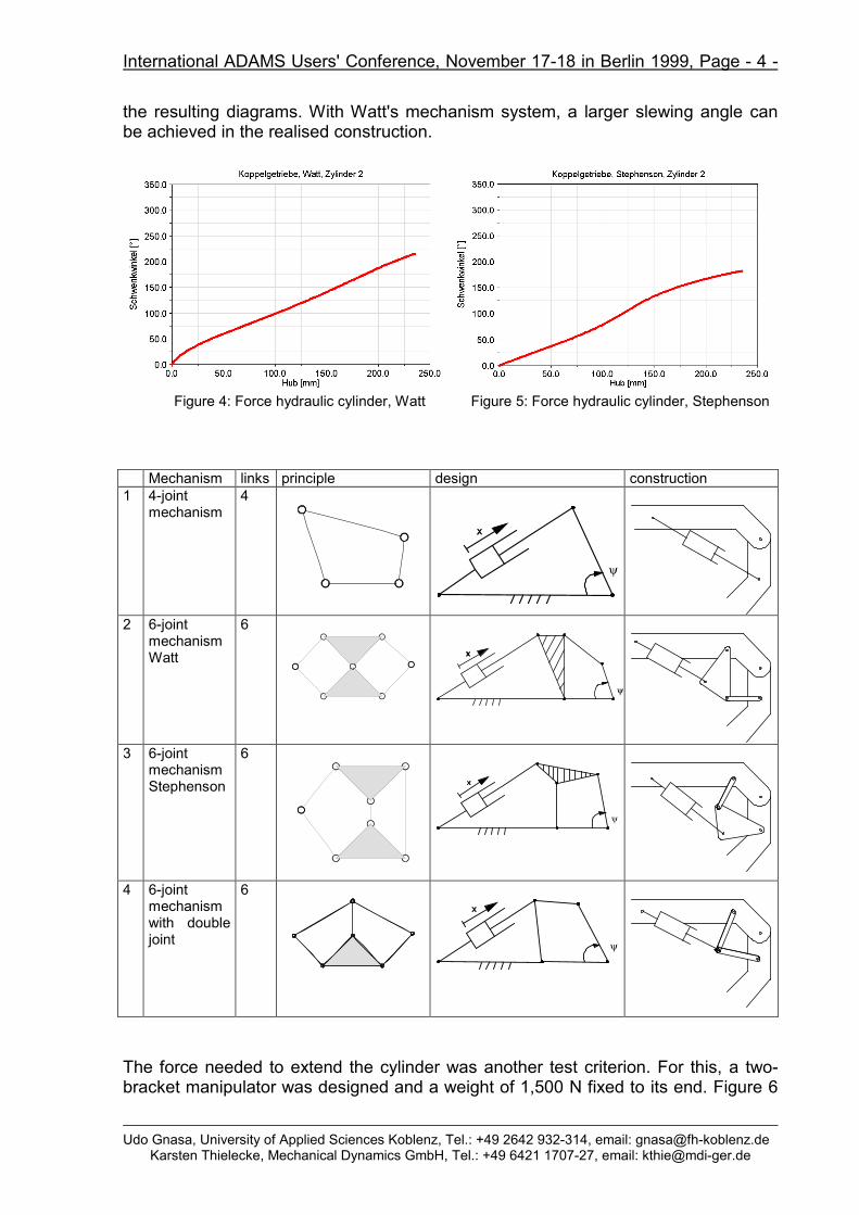
Based on the constructional solutions shown in figures 2 and 3, the maximumslewing angle was deduced, dependent on the cylindrical lift. Figures 4 and 5 show
International ADAMS Users' Conference, November 17-18 in Berlin 1999, Page - 4 -
Udo Gnasa, University of Applied Sciences Koblenz, Tel.: +49 2642 932-314, email: [email protected]
The force needed to extend the cylinder was another test criterion. For this, a two-bracket manipulator was designed and a weight of 1,500 N fixed to its end. Figure 6
International ADAMS Users' Conference, November 17-18 in Berlin 1999, Page - 5 -
Udo Gnasa, University of Applied Sciences Koblenz, Tel.: +49 2642 932-314, email: [email protected]
shows the manipulator with a partly extended end-bracket. The necessary cylinderforce was measured under the following premises: in one second, the end bracket isdriven from 0 to a lift velocity of 50 mm/s with a STEP5 function. This speed is thenkept constant to the end stop. The cylinder force needed for this was measured withboth mechanisms. Figures 7 and 8 show the results.
Based on the mentioned results, a first virtual prototype was designed. Figure 9shows the manipulator in working position. The structure is fully parametric, so thateach system parameter can be changed at any time in order to judge the effects onthe whole system. The path assigned to the end-effector can be based on any orbitand therefore on any geometry from Pro/Engineer. Figure 10 shows the prototypewith a given orbit, e.g. while working on a wall of a factory hall.
International ADAMS Users' Conference, November 17-18 in Berlin 1999, Page - 6 -
Udo Gnasa, University of Applied Sciences Koblenz, Tel.: +49 2642 932-314, email: [email protected]
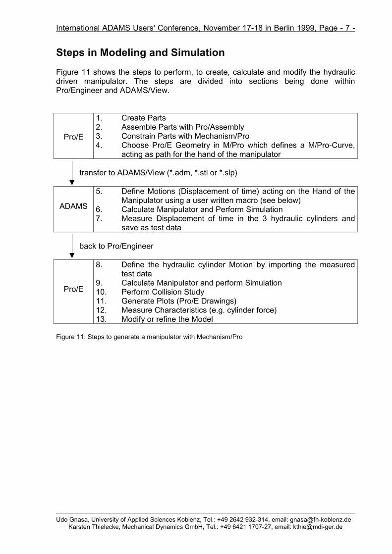
Figure 11 shows the steps to perform, to create, calculate and modify the hydraulicdriven manipulator. The steps are divided into sections being done withinPro/Engineer and ADAMS/View.
Pro/E
1. Create Parts2. Assemble Parts with Pro/Assembly3. Constrain Parts with Mechanism/Pro4. Choose Pro/E Geometry in M/Pro which defines a M/Pro-Curve,
acting as path for the hand of the manipulator
transfer to ADAMS/View (*.adm, *.stl or *.slp)
ADAMS
5. Define Motions (Displacement of time) acting on the Hand of theManipulator using a user written macro (see below)
6. Calculate Manipulator and Perform Simulation7. Measure Displacement of time in the 3 hydraulic cylinders and
save as test data
back to Pro/Engineer
Pro/E
8. Define the hydraulic cylinder Motion by importing the measuredtest data
9. Calculate Manipulator and perform Simulation10. Perform Collision Study11. Generate Plots (Pro/E Drawings)12. Measure Characteristics (e.g. cylinder force)13. Modify or refine the Model
Figure 11: Steps to generate a manipulator with Mechanism/Pro
International ADAMS Users' Conference, November 17-18 in Berlin 1999, Page - 8 -
Udo Gnasa, University of Applied Sciences Koblenz, Tel.: +49 2642 932-314, email: [email protected]
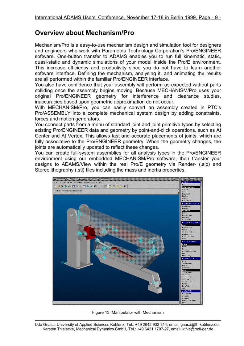
Mechanism/Pro is a easy-to-use mechanism design and simulation tool for designersand engineers who work with Parametric Technology Corporation’s Pro/ENGINEERsoftware. One-button transfer to ADAMS enables you to run full kinematic, static,quasi-static and dynamic simulations of your model inside the Pro/E environment.This increase efficiency and productivity since you do not have to learn anothersoftware interface. Defining the mechanism, analysing it, and animating the resultsare all performed within the familiar Pro/ENGINEER interface.You also have confidence that your assembly will perform as expected without partscolliding once the assembly begins moving. Because MECHANISM/Pro uses youroriginal Pro/ENGINEER geometry for interference and clearance studies,inaccuracies based upon geometric approximation do not occur.With MECHANISM/Pro, you can easily convert an assembly created in PTC’sPro/ASSEMBLY into a complete mechanical system design by adding constraints,forces and motion generators.You connect parts from a menu of standard joint and joint primitive types by selectingexisting Pro/ENGINEER data and geometry by point-and-click operations, such as AtCenter and At Vertex. This allows fast and accurate placements of joints, which arefully associative to the Pro/ENGINEER geometry. When the geometry changes, thejoints are automatically updated to reflect these changes.You can create full-system assemblies for all analysis types in the Pro/ENGINEERenvironment using our embedded MECHANISM/Pro software, then transfer yourdesigns to ADAMS/View within the real Pro/E geometry via Render- (.slp) andStereolithography (.stl) files including the mass and inertia properties.
Figure 13: Manipulator with Mechanism
International ADAMS Users' Conference, November 17-18 in Berlin 1999, Page - 10 -
Udo Gnasa, University of Applied Sciences Koblenz, Tel.: +49 2642 932-314, email: [email protected]
MarkersMarkers are coordinate systems belonging to a rigid body. Markers arefundamental ADAMS entities that you can use to define complex entities. Mostof your mechanisms can be defined without creating any marker.
•••• Multi Components ForcesA force element that consists of three orthogonal translational forcecomponents and three orthogonal torque components. In ADAMS/Solverthese types of forces are called GFORCES or General Forces.
•••• Flexible BeamsYou can define straight beams, beams on Pro/ENGINEER Datum Curves andbeams defined picking a list of Pro/ENGINEER Datum Points.
Data Elements
•••• CurvesYou can define curves referencing geometric edges and datum curves orreading curve points from an external ascii file. Defined curve entities can beused to define Point On Curve and Curve On Curve constraints. You cansimply export curves to ADAMS/View if required.
•••• Spline, Variable, ArrayYou can define ADAMS/Solver SPLINE, VARIABLE, ARRAY entities that youcan reference in motion and force functions.
•••• MeasureYou can define and plot displacement/velocity/acceleration measures betweenmarkers. Measures can be defined and plotted also after the simulation hasbeen performed!
Enhancements on existing ADAMS Entities
JointsYou can add Friction to Revolute and Translational joints.
MotionsYou can define a motion generator acting between a pair of markers.
International ADAMS Users' Conference, November 17-18 in Berlin 1999, Page - 11 -
Udo Gnasa, University of Applied Sciences Koblenz, Tel.: +49 2642 932-314, email: [email protected]
Ground ManagementMECHANISM/Pro automatically creates the ground rigid body for you andnames it as “GROUND”. The ground rigid body created by MECHANISM/Prois “empty”; this means that by default no Pro/ENGINEER assembly/partbelongs to it.You can modify the ground rigid body (adding/removing Pro/ENGINEERassemblies/parts, changing its name) but you can’t delete it.
Simulation Enhancements
Run a Custom ADAMS/SolverYou can specify a custom ADAMS/Solver to be used instead of the standardone during the simulation of your mechanism.
Modify ADAMS/Solver SettingsYou can modify the settings of each analysis type (Kinematic, Dynamic, Static)entering data in auxiliary dialog boxes.
Mechanism MergingYou can merge a previously defined mechanism into a bigger one. Define amechanism on a certain “small” assembly being a subassembly (even withmultiple instances) of a bigger one. While you are defining your mechanism onthe “big” assembly you can merge (import) the already defined smallmechanism.
Gui Enhancements
Entity SelectionRigid bodies and all the entities that are represented with a icon can beselected either by picking or selecting their names from a name list.
Modify the EntitiesEntities can be modified, you don’t need to delete an entity and create it again.
Activate/Deactivate EntitiesMost commonly used entities can be activated/deactivated, you don’t need todelete and create an entity if you want to simulate the mechanism without it.
Single Entity InfosYou can show an information window containing the properties of a singleselected entity; the entity can be selected also by pick.
Auxiliary Dialog BoxesA File Browser and Auxiliary dialog boxes appears for entering data.
On The Fly Orientation FlippingYou can flip on the fly the orientation of an entity, just click the right mousebutton.
International ADAMS Users' Conference, November 17-18 in Berlin 1999, Page - 12 -
Udo Gnasa, University of Applied Sciences Koblenz, Tel.: +49 2642 932-314, email: [email protected]
The state of your mechanism can be saved in mechanism definition file (.mprextension) having a completely new format; it is not a ADAMS/Solver Dataset file.
The .mpr file containing your mechanism definition includes the following information:• The name of the Pro/ ENGINEER assembly related to the mechanism defined in
the file.• Various MECHANISM/Pro interface settings such as Icon Size and Icon Visibility.• The current associativity between your Pro/E parts and subassemblies and your
rigid bodies.• The list of all defined entities with the associativity with your Pro/E features and
their properties.• Analysis settings:
Embedded Plot Editor
The MECHANISM/Pro Plot Editor is a powerful visual tool that allows you to definethe plottings you want to see and to examine after your simulations inside thePro/Engineer environment:• The Plot Editor allows you to define as many plots you desire and each plot can
contain as many curves you want.• You can define plot curves getting data from different analysis results.• Defined plots can be drawings inside the Pro/ENGINEER environment or can be
exported to the ADAMS/Post Processor tool.
Figure 14: MECHANISM/Pro Plot Editor
International ADAMS Users' Conference, November 17-18 in Berlin 1999, Page - 13 -
Udo Gnasa, University of Applied Sciences Koblenz, Tel.: +49 2642 932-314, email: [email protected]
References:[Enge95] Engeln, W.: Rechnergestützte Auslegungsverfahren für Großmanipulatoren mit Gelenkarmkinematik, IPA-IAO
Forschung und Praxis, 206, Springer-Verlag, 1995[Gnas96] Gnasa, U.; Modler, K.-H.; Richter, E.-R.: Computerintegrierte Entwicklung nichtlinearer Bewegungsvorgänge durch
Mechanismen mit elektrohydraulischen Antrieben; 41. IWK TU-Ilmenau, 1996[Grab97] Grabowski, H.:; Geiger, K: Neue Wege zur Produktentwicklung, Raabe Fachverlag Stuttgart, 1997[Grün95] Grün, J.: Mikroelektronische Steuerung offener Mechanismenketten durch direkte Auslegerwinkelzuordnung,
Diplomarbeit, TU Dresden 1995[Grün96] Grün, J.; Modler, K.-H.; Richter, E.-R.: Elektrohydraulische Antriebe in offenen Mechanismenketten; Kurvengetriebe,
Gelenkgetriebe, gesteuerte Antriebe; VDI-Berichte 1281, VDI-Verlag 1996[Herm95] Hermsdorf, H.: Entwurfsmethodik für Mechanismenstrukturen mit linearen Antrieben, Habilitation, TU Dresden 1995[Hill93] Hiller, M., Schneider, M.: Zwischenbericht für den Zeitraum 4.11.91 bis 1.7.93 im DFG-Vorhaben Hi 370/6-1
"Regelung von Großrobotern", Universität -GH- Duisburg, Fachgebiet Mechatronik, August 1993[Spur97] Spur, G.; Krause, F.-L.: Das virtuelle Produkt - Management der CAD-Technik, Hanser-Verlag 1997