NASA Technical Memorandum 4722 Design and Development of an F/A-18 Inlet Distortion Rake: A Cost and Time Saving Solution October 1995 Andrew J. Yuhas, Ronald J. Ray, Richard R. Burley, William G. Steenken, Leon Lechtenberg, and Don Thornton
Transcript
NASA Technical Memorandum 4722
Design and Development of an F/A-18 Inlet Distortion Rake: A Cost and Time Saving Solution
October 1995
Andrew J. Yuhas, Ronald J. Ray, Richard R. Burley,William G. Steenken, Leon Lechtenberg, and Don Thornton
NASA Technical Memorandum 4722
National Aeronautics and Space Administration
Office of Management
Scientific and Technical Information Program
1995
Andrew J. Yuhas
PRC Inc.Edwards, California
Ronald J. Ray
Dryden Flight Research CenterEdwards, California
Richard R. Burley
NASA Lewis Research CenterCleveland, Ohio
William G. Steenken, Leon Lechtenbergand Don Thornton
General Electric Aircraft EnginesEvendale, Ohio
Design and Development of an F/A-18 Inlet Distortion Rake: A Cost and Time Saving Solution
DESIGN AND DEVELOPMENT OF AN F/A-18 INLET DISTORTION RAKE: A COST AND TIME SAVING SOLUTION
Andrew J. Yuhas*
PRC Inc. Edwards, California
Ronald J. Ray**
NASA Dryden Flight Research CenterEdwards, California
Richard R. Burley†
NASA Lewis Research CenterCleveland, Ohio
William G. Steenken,†† Leon Lechtenberg‡, and Don Thornton‡‡
General Electric Aircraft EnginesEvendale, Ohio
ABSTRACT
An innovative inlet total-pressure-distortion mea-surement rake has been designed and developed for theF/A-18 A/B/C/D aircraft inlet. The design was con-ceived by NASA and General Electric Aircraft Enginespersonnel. This rake has been flight qualified and flownin the F/A-18 High Alpha Research Vehicle at NASADryden Flight Research Center, Edwards, California.The eight-legged, one-piece, wagon wheel design ofthe rake was developed at a reduced cost and offeredreduced installation time compared to traditionaldesigns. The rake features 40 dual-measurement portsfor low- and high-frequency pressure measurementswith the high-frequency transducer mounted at theport. This high-frequency transducer offers directabsolute pressure measurements from low to high fre-quencies of interest, thereby allowing the rake to beused during highly dynamic aircraft maneuvers. Out-standing structural characteristics are inherent to thedesign through its construction and use of lightweightmaterials.
NOMENCLATURE
Acronyms
AIP aerodynamic interface plane
AIR Aerospace Information Report
ALF aft looking forward
AOA angle of attack, deg
ARP Aerospace Recommended Practice
ac alternating current
CFD computational fluid dynamics
DFRC Dryden Flight Research Center, Edwards, California
F/A fighter–attack aircraft
FOD foreign object damage
GE General Electric
GEAE General Electric Aircraft Engines, Evendale, Ohio
g inertial force expressed in multiples of gravity
HARV High Alpha Research Vehicle
HATP High Alpha Technology Program
ID inside diameter
LeRC Lewis Research Center, Cleveland, Ohio
M Mach number
NASA National Aeronautics and Space Administration
NASTRAN NASA Structural Analysis, a finite element modeling program
OD outside diameter
PSI Pressure Systems Incorporated, Hampton, Virginia
PSIPP pounds force per square inch, peak to peak
RTV room temperature vulcanizing
SAE Society of Automotive Engineers
X experimental aircraft
Symbols
σ standard deviation
INTRODUCTION
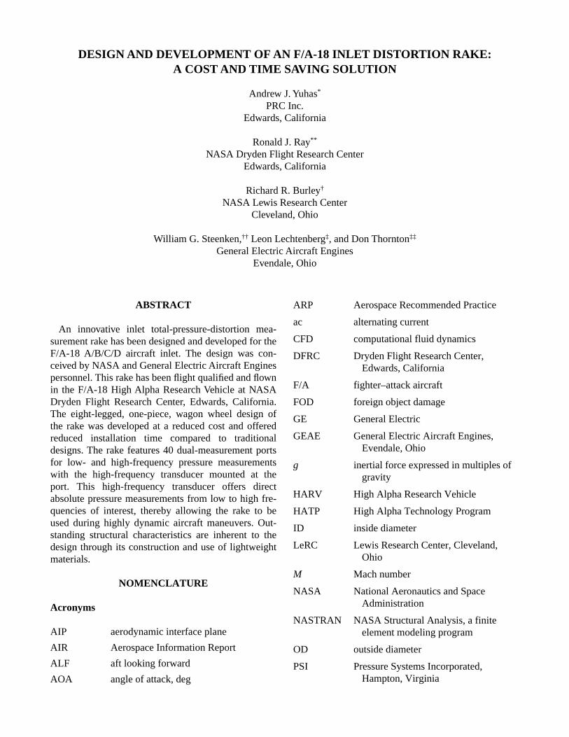
Designing, developing, and installing an inlettotal-pressure-distortion rake can be expensive andtime consuming. Figure 1 shows the F/A-18 HighAlpha Research Vehicle (HARV) being flown at NASADryden Flight Research Center (DFRC), Edwards, Cal-ifornia. The HARV inlet research program goalsrequired a low-cost, short-installation-time, and low-maintenance solution to meet the need for a total-pressure inlet-distortion measurement system. TheHARV inlet research program evaluates the inletcharacteristics of high-performance aircraft during
stabilized and highly dynamic maneuvers at highangles of attack.
Traditional inlet rake systems typically use eight-legged, duct-mounted cantilevered designs, such asthose used on the developmental F/A-18A1 or inletguide vane leading-edge designs.2 These designs havecommonly required extensive modifications to the air-craft or the engine. In particular, the cantilevered sys-tem, with its individual rake leg designs andinstallations, can be costly, because of separate rake legdevelopment and testing. In addition, this system canbe time consuming because of increased structuralmodifications of the aircraft and flight qualificationtesting.
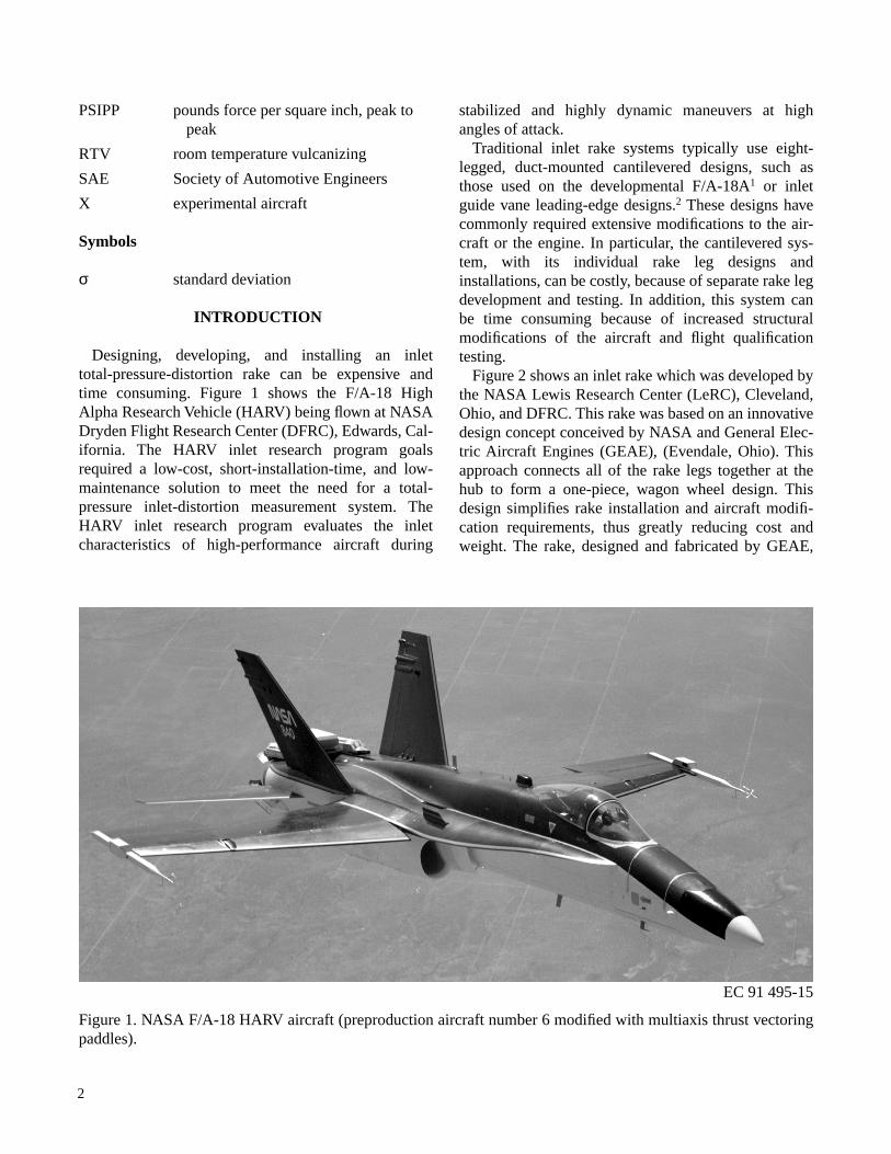
Figure 2 shows an inlet rake which was developed bythe NASA Lewis Research Center (LeRC), Cleveland,Ohio, and DFRC. This rake was based on an innovativedesign concept conceived by NASA and General Elec-tric Aircraft Engines (GEAE), (Evendale, Ohio). Thisapproach connects all of the rake legs together at thehub to form a one-piece, wagon wheel design. Thisdesign simplifies rake installation and aircraft modifi-cation requirements, thus greatly reducing cost andweight. The rake, designed and fabricated by GEAE,
2
EC 91 495-15
Figure 1. NASA F/A-18 HARV aircraft (preproduction aircraft number 6 modified with multiaxis thrust vectoringpaddles).
has passed the needed flight qualification requirementsand has been flown on the HARV.
This paper describes the design, fabrication, installa-tion, and qualification testing of the HARV inlet rakesystem. Comparisons of cost and installation timebetween this design and a previous design are made.The paper also details the design requirements andpressure transducer selection. All stages of flight quali-fication testing, from laboratory to flight test, aredescribed.
Use of tradenames or names of manufacturers in thispaper does not constitute an official endorsement ofsuch products or manufacturers, either expressed orimplied, by the National Aeronautics and SpaceAdministration.
INLET RAKE SYSTEM REQUIREMENTS
When considering an inlet rake design for use on theF/A-18 HARV flight program, the basic requirementswere first established. The most important requirementwas to provide as much commonality as practical withthe planned HARV inlet wind tunnel test at the LeRCand with previous F/A-18 inlet testing. Commonalityconsiderations with past and present testing included
but were not limited to instrumentation setup, rakepositioning, and probe configuration. The design alsohad to allow accurate data measurements to be gath-ered to meet all of the HARV inlet research objectives.This requirement primarily concerned instrumentationselection. In addition, following established industryguidelines wherever possible was desired. Consider-ations of cost and installation time are always impor-tant factors that ultimately constrained the designrequirements.
Commonality
Inlet instrumentation was required on the HARV tocorrelate flight data with and verify test results from theplanned 9- by 15-ft wind tunnel tests scheduled at theLeRC as part of the High Alpha Technology Program(HATP) inlet research program. In that aspect, theHARV instrumentation was developed to emulate thewind tunnel set, limited primarily by the cost and com-plexity of modifying the full-scale vehicle.
Having commonality between the current flight testrake and previous F/A-18 flight test rakes was alsodesirable. In the mid-1970’s, the U.S. Navy along withindustry partners, McDonnell Douglas Aerospace
3
EC 93 41084-7
Figure 2. NASA and GEAE inlet pressure distortion rake mounted in HARV right inlet.
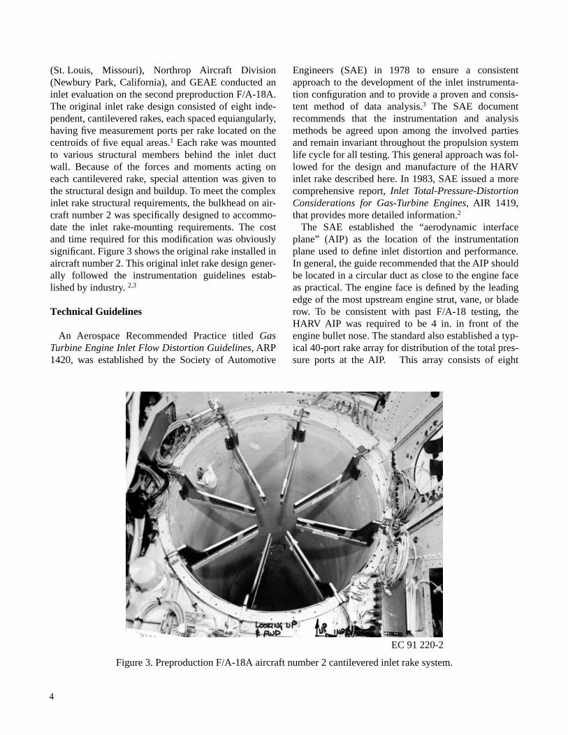
(St. Louis, Missouri), Northrop Aircraft Division(Newbury Park, California), and GEAE conducted aninlet evaluation on the second preproduction F/A-18A.The original inlet rake design consisted of eight inde-pendent, cantilevered rakes, each spaced equiangularly,having five measurement ports per rake located on thecentroids of five equal areas.1 Each rake was mountedto various structural members behind the inlet ductwall. Because of the forces and moments acting oneach cantilevered rake, special attention was given tothe structural design and buildup. To meet the complexinlet rake structural requirements, the bulkhead on air-craft number 2 was specifically designed to accommo-date the inlet rake-mounting requirements. The costand time required for this modification was obviouslysignificant. Figure 3 shows the original rake installed inaircraft number 2. This original inlet rake design gener-ally followed the instrumentation guidelines estab-lished by industry. 2,3
Technical Guidelines
An Aerospace Recommended Practice titled GasTurbine Engine Inlet Flow Distortion Guidelines, ARP1420, was established by the Society of Automotive
Engineers (SAE) in 1978 to ensure a consistentapproach to the development of the inlet instrumenta-tion configuration and to provide a proven and consis-tent method of data analysis.3 The SAE documentrecommends that the instrumentation and analysismethods be agreed upon among the involved partiesand remain invariant throughout the propulsion systemlife cycle for all testing. This general approach was fol-lowed for the design and manufacture of the HARVinlet rake described here. In 1983, SAE issued a morecomprehensive report, Inlet Total-Pressure-DistortionConsiderations for Gas-Turbine Engines, AIR 1419,that provides more detailed information.2
The SAE established the “aerodynamic interfaceplane” (AIP) as the location of the instrumentationplane used to define inlet distortion and performance.In general, the guide recommended that the AIP shouldbe located in a circular duct as close to the engine faceas practical. The engine face is defined by the leadingedge of the most upstream engine strut, vane, or bladerow. To be consistent with past F/A-18 testing, theHARV AIP was required to be 4 in. in front of theengine bullet nose. The standard also established a typ-ical 40-port rake array for distribution of the total pres-sure ports at the AIP. This array consists of eight
equiangularly spaced rakes with five ports per rakelocated at the centroids of equal areas. The originalF/A-18 rake (fig. 3) followed this configuration andwas clocked (rotated clockwise aft looking forward(ALF)) approximately 9°. Clocking the rake is oftenrequired because of structure installation consider-ations. The HARV inlet flight test program goal was tomeet this arrangement. Because the original F/A-18Arake was installed in the left inlet, the HARV rake, tobe installed in the right inlet, was required to beclocked counterclockwise ALF approximately 9°. Thisconfiguration would make the installation equivalentbecause of symmetry.
HARV Inlet Research Objectives
Another consideration necessary for the design of theinlet rake was its intended use during the HARV inletresearch flight test. The primary objectives of theresearch were as follows: 1. Determine whether highly dynamic aircraft
maneuvers result in a significant increase in inletpressure distortion levels compared to correspond-ing steady-flight conditions.
2. Determine whether sources other than spatial time-variant distortion lead to engine aerodynamicinstabilities during aircraft departures.
3. Assess predicted inlet distortion from computa-tional fluid dynamics (CFD) as compared to flighttest measured levels.
These objectives have the dual requirement for gath-ering accurate inlet measurements during stabilizedand dynamic maneuvers, including aircraft departures.The instrumentation setup for dynamic maneuverswould require more attention than the setup for stabi-lized maneuvers.
Instrumentation
Inlet pressure distortion instrumentation typically hasthe requirement for accurately measuring pressure lev-els at high frequencies. This requirement is typicallyachieved by measuring the inlet characteristics with adual-probe configuration using low- and high-frequency response sensors. The low-frequencyresponse probe usually consists of pneumatic tubingrouted through and beyond the rake where it is con-nected to a highly accurate transducer. This pressure
transducer can either be absolute or differential (withan accurate reference source). This response systemmeasures an accurate absolute pressure level. Thehigh-frequency response probe typically consists of aminiature transducer mounted at the AIP. This responsesystem measures the time-dependent component of thepressure but, normally, not an accurate absolute pres-sure level.
The HARV research objectives required instrumenta-tion to measure stabilized and dynamic maneuvers.The typical instrumentation setup described in the pre-vious paragraph would not be adequate to meet thedemanding requirement of measuring inlet characteris-tics during dynamic maneuvers without introducing alarge amount of measurement uncertainty. The HARVrequires a system which would minimize the effects oftwo known drawbacks of the typical instrumentationsetup that affect the ability to measure an accurate pres-sure level during a dynamic maneuver: pneumatic lagand thermal zero shift. Pneumatic lag describes thecondition where the pressure signal at the AIP isdelayed in reference to time to the transducer at the endof the tubing and, therefore, affects low-frequencyresponse accuracy. Thermal zero shift affects the abil-ity of the low- and, especially, the high-frequencyresponse transducer to accurately measure the pressurelevel at varying inlet temperature conditions. Thermalzero shift describes the calibration shift of the zerovoltage condition experienced as a pressure-sensingelement of the transducer varies with temperature.Thus, the requirement was to develop an instrumenta-tion setup that would allow for accurate measurementof the pressure level and the time-dependent compo-nent of the pressure during highly dynamic maneuvers.
The requirements for pressure and temperatureranges were determined by the flight conditions whereresearch testing would take place. The HARV researchoccurred between an altitude from 15,000 to 40,000 ftand below Mach 0.9 (fig. 4). The necessary instrumen-tation pressure range was determined to be 2 to 16 psia.The temperature was from 395 to 618 °R.
Other instrumentation considerations outlined byindustry through the SAE3 include that “the frequencyresponse characteristic of the probe and transducercombination should be determined with reference tosystem accuracy requirements.” GEAE determined thatthe highest frequency of interest for the F404-GE-400engine was 105 Hz. NASA chose to increase the high-est frequency of interest to 250 Hz. Industry require-ments for the highest frequency of interest vary. NASA
5
required the higher range to allow the HARV inletresearch database to be used by all interested industrycustomers. The instrumentation accuracy requirementneeded to meet or exceed the original F/A-18A flighttest. This testing called for the following system accu-racy as a percent of reading (2σ): 3.2 percent at 2 psia,1.3 percent at 5 psia, and 1 percent at 32 psia.1
A final requirement stated for the instrumentationwas ease of maintainability. Transducers needed to beaccessible without engine removal. The ability toreplace the transducer without removing the enginewas also desirable. Additionally, the transducer orprobe configuration should provide the sensing elementof the transducer with protection from foreign objectdamage (FOD).
Aerodynamic and Structural Requirements
Figure 4 shows the aerodynamic design flight enve-lope. This envelope coincides with the normal operat-ing envelope of the HARV aircraft and was chosen toallow unrestricted flight with the inlet rake installed.Inlet research test points were primarily focused at thelow-speed portion of the envelope between Mach 0.3and Mach 0.4. The worse-case dynamic pressure con-dition was at a Mach 0.7 at sea level conditions where
the freestream total pressure was 20.4 psia, and the hotday total temperature was 618 °R.
Requirements for the inlet rake design included addi-tional aerodynamic and structural considerations.Designing the rake legs and center hub with an aerody-namic shape that minimized airflow disturbance andwith a blockage factor as small as possible was desir-able. The HARV blockage goal was to be equal to orless than the previous F/A-18A inlet rake design,which had a flow blockage of less than 8 percent.1
Structural requirements included meeting the worse-case pressure loads. These loads include an inlet ham-mershock overpressure of 20 psi maximum caused byan engine surge. The HARV structural load limits withthe thrust vectoring vanes installed are 5.4 normal gloads and 2.0 lateral g loads. Of particular concern wasthe requirement to meet dynamic structural require-ments as outlined in DFRC document “Process Specifi-cation 21-2, Environmental Testing Electronic andElectromechanical Equipment.”* In particular, the rakehad to be designed stiff enough so that it did not exceedstress limits at its predominant structural frequencies
*NASA Dryden internal document, “Process Specification 21-2,Environmental Testing Electronic and Electromechanical Equip-ment.” Original released on May, 1968 with current updates untilApr. 1989.
6
Figure 4. HARV inlet rake design flight envelope.
.4 .6 Mach number
.8 1.0.20
10
20
30
40
50 x 103
Altitude, ft
940086
450 kts
within the airframe and engine operating range. NASAalso wanted a number of structural materials consid-ered for the rake including composite materials. Use ofcomposites could translate into a lighter, more aerody-namic design along with structural tailoring of the rakearms as compared to traditional designs.
Cost and Time Considerations
Two of the critical requirements that had to be metfor the HARV inlet rake design were low cost and min-imal installation time. An evaluation of the rake used inthe original F/A-18 inlet compatibility program indi-cated costs in excess of $1.5 million and installationtime on the order of 1 year or more. Driving both thesefactors were the complexity of using eight cantileverrakes. Those designs had to be developed, tested, andinstalled independently. Installation would require theaft portion of the inlet duct to be extensively rein-forced. Thus, this evaluation quickly revealed that thisapproach was not viable for the HARV project. A liter-ature search of past rake designs did not provide a via-ble alternative approach.4,5
During an early design conception meeting, NASAand GEAE personnel conceived an alternativeapproach in which the eight rake legs would be joinedat the center of the inlet with a hub similar to that of awagon wheel. The rake would thus be one piece andwould only have to consider shear loads (no moments)at its attachment points. This alternative would greatlysimplify the structural installation requirements. Also,it was envisioned that the rake would slip up the backof the inlet ahead of the engine and attach to the mainbulkhead near this location.
Similar wagon wheel rake designs of the past differfrom the NASA and GEAE approach. Previous designstypically used a modified engine bullet nose whichacted as the hub. The NASA and GEAE concept wouldbe self-supported with no physical contact with theengine. This design would minimize vibrational andforce transfer from the engine. The NASA and GEAEdesign would greatly simplify installation and aircraftmodifications and significantly reduce aircraftdown time. GEAE has successfully designed, devel-oped and built one prototype and two flight-worthyrakes for less than $500,000. One flight-worthy rakehad an entire set of high-frequency response transduc-ers included in the cost. The design details and specifi-cations associated with the delivered rake along withits flight qualification testing are described in the
HARV Inlet Rake System and Flight QualificationTesting sections.
One significant advantage of the new rake designincludes its transportability to other aircraft which useF404-GE-400 engines, such as other F/A-18, X-29, andX-31 aircraft. GEAE is currently under contract todetermine the feasibility of extending the currentdesign to supersonic flight conditions and to scale thisdesign to larger inlet diameters.
HARV INLET RAKE SYSTEM
This section describes the HARV Inlet Rake System.The design and development of the HARV inlet rakesystem are detailed in the Rake Description, PressureTransducer Selection, and Rake Fabrication subsec-tions. Placement of the rake into the HARV isdescribed in the Rake Installation subsection. A sum-mary description of the rake system is described in theOperating Principles subsection.
Rake Description
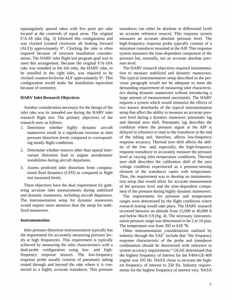
The HARV rake is similar to a wagon wheel with thestreamlined centerbody acting as the hub, the eightaerodynamic rake bodies being the spokes, and theinlet duct being the rim. The load-bearing structure is awelded Inconel 625* unit that joins the rake bodies andthe central hub into a single piece that is supported byintegral footpads and bolted to the aircraft inlet ductflange (fig. 5). Each of the eight rake legs contain fiveports located on the centroids of five equal areas of theflow area. The ports are aligned within 2° of the antici-pated steady-flow streamlines. The innermost port isthe only one that had to be angled (5.5°) with respect tothe rake body. All others were already within 2° of theflow angle.
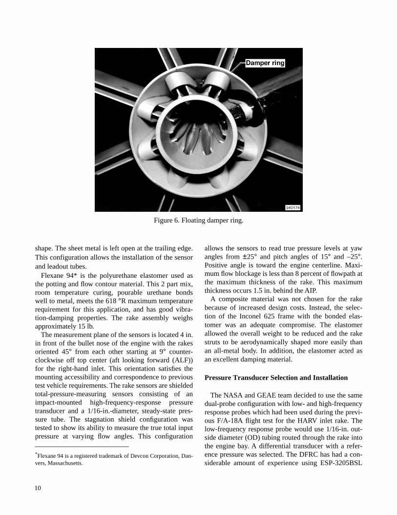
The central hub also contains an isolated metaldamper ring potted in the polyurethane centerbody(fig. 6). This configuration allows the damping materialto dissipate vibration energy more effectively than anall-metal body. The same polyurethane material alsoforms the streamlining of both the centerbody and thetrailing edges of the rake bodies. The rake bodies(or spokes) of the structure are made by forming sheetmetal into the leading edge and sides of the airfoil
*Inconel 625 is a registered trademark of Huntington Alloy Prod-ucts Division, International Nickel Company, Huntington Beach,West Virginia.
7
(a)
Fron
t and
sid
e vi
ews.
Figu
re 5
. Inl
et d
isto
rtio
n ra
ke.
D
9400
96
D
C
CF
ron
t vi
ew o
f ra
ke
Sec
tio
n B
Sec
tio
n A
Sid
e vi
ew o
f ra
ke
En
gin
e b
ulle
t n
ose
Met
al d
amp
er r
ing
8
(b)
Sect
ions
A th
roug
h D
.
Figu
re 5
. Con
clud
ed.
Lea
d-o
ut
tub
es
Mea
sure
men
t p
ort
S
ecti
on
AM
ou
nti
ng
inst
alla
tio
n
Sec
tio
n B
Fo
otp
ad
Sec
tio
n C
Rak
e b
od
y cr
oss
-sec
tio
n
Sec
tio
n D
K-s
eal
En
gin
e f
ron
t fr
ame
Ep
oxy
fill
er
Fu
sela
ge
bu
lkh
ead
Sh
im Fo
otp
ad
Sta
gn
atio
n s
hie
ld
Sh
rin
k tu
be
Hig
h-f
req
uen
cy
res
po
nse
tra
nsd
uce
r
Lo
w-f
req
uen
cy r
esp
on
se
pn
eum
atic
tu
bin
g
Met
al r
ake
bo
dy
Ela
sto
mer
fill
er
Lea
d-o
ut
tub
es
Bo
lt h
ole
s
9401
73
9
Figure 6. Floating damper ring.
shape. The sheet metal is left open at the trailing edge.This configuration allows the installation of the sensorand leadout tubes.
Flexane 94* is the polyurethane elastomer used asthe potting and flow contour material. This 2 part mix,room temperature curing, pourable urethane bondswell to metal, meets the 618 °R maximum temperaturerequirement for this application, and has good vibra-tion-damping properties. The rake assembly weighsapproximately 15 lb.
The measurement plane of the sensors is located 4 in.in front of the bullet nose of the engine with the rakesoriented 45° from each other starting at 9° counter-clockwise off top center (aft looking forward (ALF))for the right-hand inlet. This orientation satisfies themounting accessibility and correspondence to previoustest vehicle requirements. The rake sensors are shieldedtotal-pressure-measuring sensors consisting of animpact-mounted high-frequency-response pressuretransducer and a 1/16-in.-diameter, steady-state pres-sure tube. The stagnation shield configuration wastested to show its ability to measure the true total inputpressure at varying flow angles. This configuration
*Flexane 94 is a registered trademark of Devcon Corporation, Dan-vers, Massachusetts.
allows the sensors to read true pressure levels at yawangles from ±25° and pitch angles of 15° and –25°.Positive angle is toward the engine centerline. Maxi-mum flow blockage is less than 8 percent of flowpath atthe maximum thickness of the rake. This maximumthickness occurs 1.5 in. behind the AIP.
A composite material was not chosen for the rakebecause of increased design costs. Instead, the selec-tion of the Inconel 625 frame with the bonded elas-tomer was an adequate compromise. The elastomerallowed the overall weight to be reduced and the rakestruts to be aerodynamically shaped more easily thanan all-metal body. In addition, the elastomer acted asan excellent damping material.
Pressure Transducer Selection and Installation
The NASA and GEAE team decided to use the samedual-probe configuration with low- and high-frequencyresponse probes which had been used during the previ-ous F/A-18A flight test for the HARV inlet rake. Thelow-frequency response probe would use 1/16-in. out-side diameter (OD) tubing routed through the rake intothe engine bay. A differential transducer with a refer-ence pressure was selected. The DFRC has had a con-siderable amount of experience using ESP-3205BSL
10
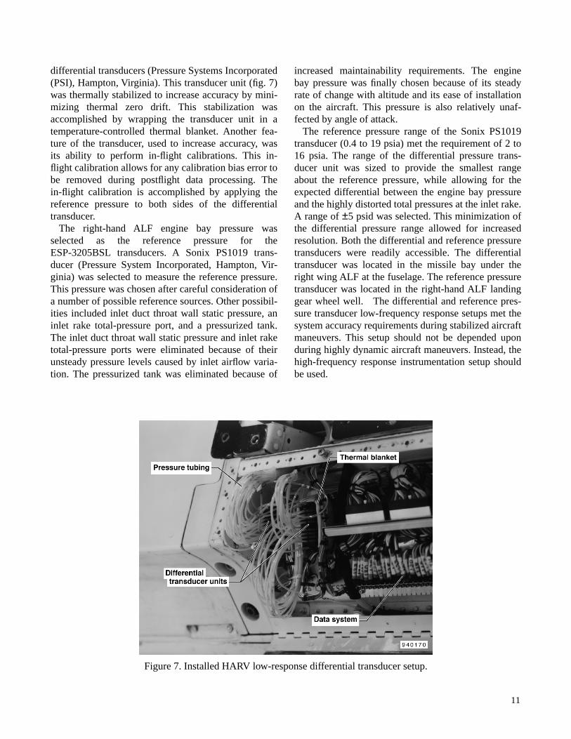
differential transducers (Pressure Systems Incorporated(PSI), Hampton, Virginia). This transducer unit (fig. 7)was thermally stabilized to increase accuracy by mini-mizing thermal zero drift. This stabilization wasaccomplished by wrapping the transducer unit in atemperature-controlled thermal blanket. Another fea-ture of the transducer, used to increase accuracy, wasits ability to perform in-flight calibrations. This in-flight calibration allows for any calibration bias error tobe removed during postflight data processing. Thein-flight calibration is accomplished by applying thereference pressure to both sides of the differentialtransducer.
The right-hand ALF engine bay pressure wasselected as the reference pressure for theESP-3205BSL transducers. A Sonix PS1019 trans-ducer (Pressure System Incorporated, Hampton, Vir-ginia) was selected to measure the reference pressure.This pressure was chosen after careful consideration ofa number of possible reference sources. Other possibil-ities included inlet duct throat wall static pressure, aninlet rake total-pressure port, and a pressurized tank.The inlet duct throat wall static pressure and inlet raketotal-pressure ports were eliminated because of theirunsteady pressure levels caused by inlet airflow varia-tion. The pressurized tank was eliminated because of
increased maintainability requirements. The enginebay pressure was finally chosen because of its steadyrate of change with altitude and its ease of installationon the aircraft. This pressure is also relatively unaf-fected by angle of attack.
The reference pressure range of the Sonix PS1019transducer (0.4 to 19 psia) met the requirement of 2 to16 psia. The range of the differential pressure trans-ducer unit was sized to provide the smallest rangeabout the reference pressure, while allowing for theexpected differential between the engine bay pressureand the highly distorted total pressures at the inlet rake.A range of ±5 psid was selected. This minimization ofthe differential pressure range allowed for increasedresolution. Both the differential and reference pressuretransducers were readily accessible. The differentialtransducer was located in the missile bay under theright wing ALF at the fuselage. The reference pressuretransducer was located in the right-hand ALF landinggear wheel well. The differential and reference pres-sure transducer low-frequency response setups met thesystem accuracy requirements during stabilized aircraftmaneuvers. This setup should not be depended uponduring highly dynamic aircraft maneuvers. Instead, thehigh-frequency response instrumentation setup shouldbe used.
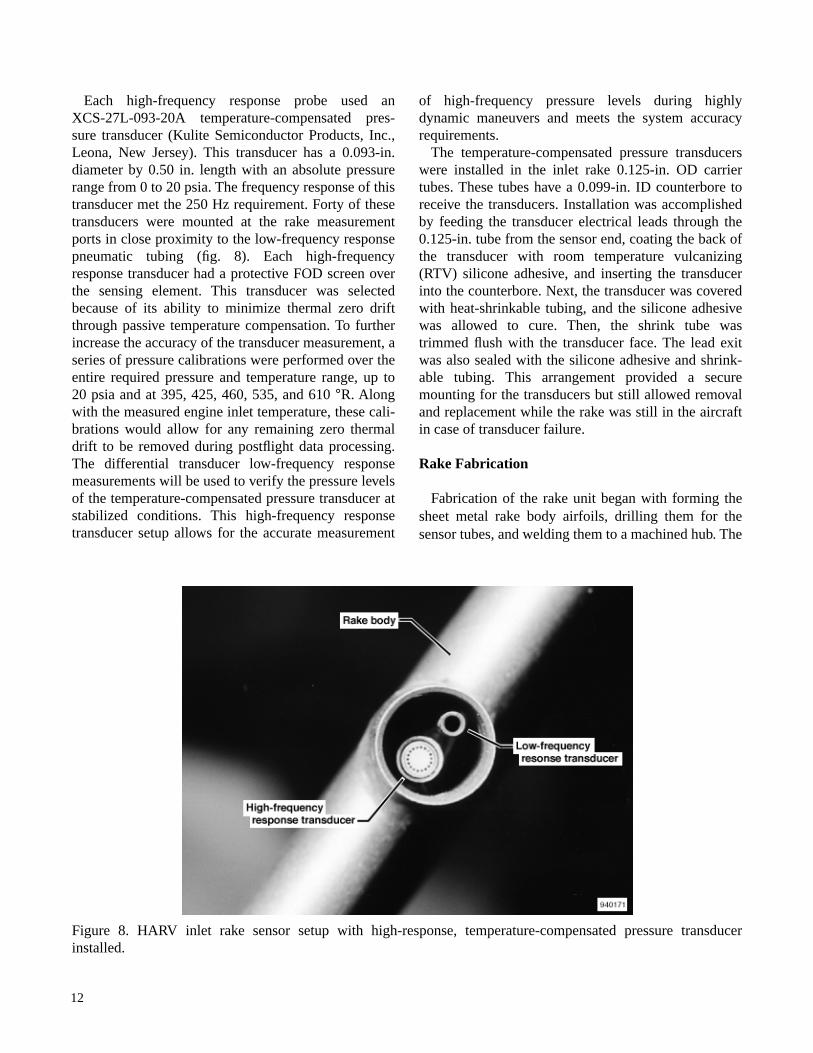
Each high-frequency response probe used anXCS-27L-093-20A temperature-compensated pres-sure transducer (Kulite Semiconductor Products, Inc.,Leona, New Jersey). This transducer has a 0.093-in.diameter by 0.50 in. length with an absolute pressurerange from 0 to 20 psia. The frequency response of thistransducer met the 250 Hz requirement. Forty of thesetransducers were mounted at the rake measurementports in close proximity to the low-frequency responsepneumatic tubing (fig. 8). Each high-frequencyresponse transducer had a protective FOD screen overthe sensing element. This transducer was selectedbecause of its ability to minimize thermal zero driftthrough passive temperature compensation. To furtherincrease the accuracy of the transducer measurement, aseries of pressure calibrations were performed over theentire required pressure and temperature range, up to20 psia and at 395, 425, 460, 535, and 610 °R. Alongwith the measured engine inlet temperature, these cali-brations would allow for any remaining zero thermaldrift to be removed during postflight data processing.The differential transducer low-frequency responsemeasurements will be used to verify the pressure levelsof the temperature-compensated pressure transducer atstabilized conditions. This high-frequency responsetransducer setup allows for the accurate measurement
of high-frequency pressure levels during highlydynamic maneuvers and meets the system accuracyrequirements.
The temperature-compensated pressure transducerswere installed in the inlet rake 0.125-in. OD carriertubes. These tubes have a 0.099-in. ID counterbore toreceive the transducers. Installation was accomplishedby feeding the transducer electrical leads through the0.125-in. tube from the sensor end, coating the back ofthe transducer with room temperature vulcanizing(RTV) silicone adhesive, and inserting the transducerinto the counterbore. Next, the transducer was coveredwith heat-shrinkable tubing, and the silicone adhesivewas allowed to cure. Then, the shrink tube wastrimmed flush with the transducer face. The lead exitwas also sealed with the silicone adhesive and shrink-able tubing. This arrangement provided a securemounting for the transducers but still allowed removaland replacement while the rake was still in the aircraftin case of transducer failure.
Rake Fabrication
Fabrication of the rake unit began with forming thesheet metal rake body airfoils, drilling them for thesensor tubes, and welding them to a machined hub. The
footpads were then machined, formed to the ductradius, and welded to the rake bodies. After stressrelieving, the welds were inspected using the florescentpenetrant inspection technique. (This nondestructiveinspection technique detects cracks by applying a pen-etrating fluorescent solvent to the material.) Sensortubes and stagnation shields were then brazed in placewith a gold and nickel braze. The bend radii in theleadout tubes were kept as large as possible to facilitateinstallation of the transducer leads later in the assembly(fig. 9). A damper ring was then installed around thehub and rake struts. Welds and brazes were reinspectedafter the metal fabrication portion of the assembly con-cluded. Strain gages were applied to the hub and rakebodies in the areas that would later be covered withpolyurethane elastomer (fig. 10). The rake bodies werethen filled and the trailing edges of the rakes wereformed with the elastomer. The center hub form wasthen cast in place completing the airfoil blending of therakes and centerbody. Figure 11 shows the completedrake assembly.
Rake Installation
Installation of the rake on the aircraft was accom-plished after the right-hand engine (ALF) had beenremoved. The minimal airframe modifications thatwere required consisted of 1/4-in. bolt holes beingdrilled in the inlet duct flange aft of the rear bulkhead.These 16 holes were located by trial positioning therake in the inlet duct, confirming that none of the boltholes would interfere with any bulkhead bracing, andtransfer-punching the hole locations through the rake-mounting footpads. Then, the rake assembly wasremoved, and the holes were drilled in the flange usinga hand-held drill. Backup washers were then placed ateach hole on the outside of the duct and expoxied inplace to provide a solid and flat surface for seating thenuts of the rake-mounting bolts (fig. 5). This seatingwas done by inserting a nylon mandrel through thewasher and rake-mounting holes in the duct to positionthe washers on an aluminum-filled epoxy base thatfilled the gap under the washer. These mandrels wereremoved after the epoxy had cured overnight.
13
EC 92 5192-3
Figure 9. Rake leg instrumentation tube leadouts.
S 3405-2
Figure 10. Stain-gaged hub of distortion rake.
S 825-3
Figure 11. Completed prototype distortion rake with polyurethane elastomer rake leg fairings and centerbody.
14
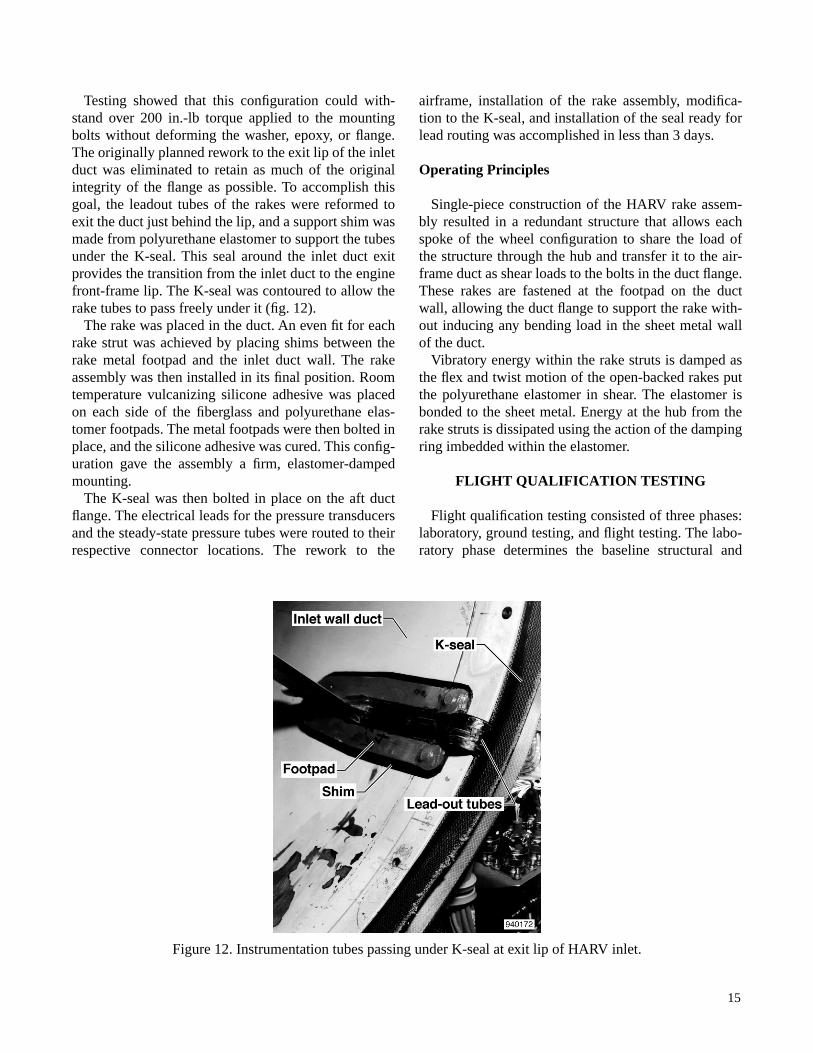
Testing showed that this configuration could with-stand over 200 in.-lb torque applied to the mountingbolts without deforming the washer, epoxy, or flange.The originally planned rework to the exit lip of the inletduct was eliminated to retain as much of the originalintegrity of the flange as possible. To accomplish thisgoal, the leadout tubes of the rakes were reformed toexit the duct just behind the lip, and a support shim wasmade from polyurethane elastomer to support the tubesunder the K-seal. This seal around the inlet duct exitprovides the transition from the inlet duct to the enginefront-frame lip. The K-seal was contoured to allow therake tubes to pass freely under it (fig. 12).
The rake was placed in the duct. An even fit for eachrake strut was achieved by placing shims between therake metal footpad and the inlet duct wall. The rakeassembly was then installed in its final position. Roomtemperature vulcanizing silicone adhesive was placedon each side of the fiberglass and polyurethane elas-tomer footpads. The metal footpads were then bolted inplace, and the silicone adhesive was cured. This config-uration gave the assembly a firm, elastomer-dampedmounting.
The K-seal was then bolted in place on the aft ductflange. The electrical leads for the pressure transducersand the steady-state pressure tubes were routed to theirrespective connector locations. The rework to the
airframe, installation of the rake assembly, modifica-tion to the K-seal, and installation of the seal ready forlead routing was accomplished in less than 3 days.
Operating Principles
Single-piece construction of the HARV rake assem-bly resulted in a redundant structure that allows eachspoke of the wheel configuration to share the load ofthe structure through the hub and transfer it to the air-frame duct as shear loads to the bolts in the duct flange.These rakes are fastened at the footpad on the ductwall, allowing the duct flange to support the rake with-out inducing any bending load in the sheet metal wallof the duct.
Vibratory energy within the rake struts is damped asthe flex and twist motion of the open-backed rakes putthe polyurethane elastomer in shear. The elastomer isbonded to the sheet metal. Energy at the hub from therake struts is dissipated using the action of the dampingring imbedded within the elastomer.
FLIGHT QUALIFICATION TESTING
Flight qualification testing consisted of three phases:laboratory, ground testing, and flight testing. The labo-ratory phase determines the baseline structural and
15
Figure 12. Instrumentation tubes passing under K-seal at exit lip of HARV inlet.
vibrational characteristics of the rake. This phase con-sists of rake modeling using NASA Structural Analysis(NASTRAN) along with Zonic ping (Zonic Corpora-tion, Milford, Ohio) and vibrational shake table(Unholtz-Dickie Corporation, Wallingford, Connecti-cut) testing on a prototype rake. Results of this phaseare compared to the environmental conditions that therake will experience in operation. Then, baselineresults from the laboratory tests are used for compari-son with the results from the installed ground testingand flight testing phases. Each phase is described in thefollowing subsections.
Laboratory Testing
Computer modeling of the rake structure using theNASTRAN program was used to identify the possiblevibration modes and the approximate frequencies ofthose modes. The computer model identified 15 poten-tial vibrational modes between 0 to 7000 Hz. Most ofthese modes could not be driven to significant levelsduring subsequent laboratory, ground, or flight testing.
The laboratory testing used a prototype rake instru-mented with strain gages. This rake was installed in aninlet test fixture manufactured from a modified F/A-18aircraft inlet. This test phase consisted of ping tests andvibration table testing. Objectives of vibration testingwith the instrumented prototype were to:1. Measure the vibration characteristics of the rake
with axial and transverse excitation.
2. Determine the rake stress distribution at an estab-lished maximum rake stress level.
3. Excite the rake randomly at the flight qualificationexcitation level for a specified period without dam-aging the rake.
4. Excite the rake sinusoidally at its resonant fre-quency at a specified excitation level to empiricallydefine the rake endurance limit.
5. Select the critical strain gage locations for groundtest monitoring based on the strain-gage-derivedstress distribution.
Twenty-eight dynamic strain gages were applied totwo (of eight) rake struts. That is, 14 each on 2 strutsspaced 90° with respect to each other and circum-ferentially oriented in the inlet so that one of theinstrumented struts would be exposed to maxi-mum excitation during the transverse vibration test. In
addition, accelerometers were mounted on the inlet testfixture and on the vibration table. This instrumentationwould verify that there was no displacement amplifica-tion caused by resonance of the test fixture. This instru-mentation was also used to verify the predicteddamping characteristics of the rake structure.
Strain gage excitation and signal conditioning wereaccomplished by a GEAE designed and fabricated con-stant current excitation, alternating current (ac) cou-pled amplification system. Data were recorded on anX-Y plotter to show overall strain levels as a functionof frequency. The instrumented inlet test fixture andrake assembly was mounted on a 17,500 lb capacityvibration table.
The ping test uses an instrumented hammer forapplying a force to the rake structure and measures theresultant motion of the rake. This method identifiedfour primary modes at which the rake might be driven.These modes were axial, torsion, strut bending, andsecond axial.
Vibration table testing consisted of three procedures:axial-sinusoidal, transverse-sinusoidal, and transverse-random excitation. The axial- and transverse-sinusoidalvibration test procedures required several steps. First,the rake was excited axially with respect to the enginecenterline. Next, the rake was excited transverselyusing sinusoidal-driving forces over the frequencyfrom 10 to 2000 Hz at 1-g excitation to locate the reso-nant frequencies of the rake. Then, the axial and trans-verse stress distributions were obtained by dwelling atthe resonant points and increasing the input accelera-tion levels until the established maximum stress levelwas reached on one of the strain gages. Subsequently,the rake was exposed to transverse-random excitation(nonsinusoidal) over the frequency range of 15 to2000 Hz at 18.4-g excitation (flight qualification level).Finally, the rake was vibrated at resonance at an excita-tion level necessary to verify the rake endurance limit.
Rake maximum stress levels were established by tak-ing a number of factors into consideration. These fac-tors included the material properties of the rakestructure, placement and number of strain gagesinstalled, stress concentrations, and safety margin. Thestress limits of 30,000 and 50,000 lb/in2 peak-to-peak(PSIPP), dependent on strain gage location, were used.
The axial-input frequency resonant sweep testshowed an axial mode at 147 Hz with 1-g excitation.The input acceleration level was then increased untilthe maximum stress level of 30,000 PSIPP wasreached. The maximum strain gage outputs were
16
located on the leading edge and trailing edge of therake foil at the hub. A decrease in the axial mode fre-quency to 129 Hz at 3.8-g excitation was observed. Themaximum response of 30,000 PSIPP at 3.8-g axialinput meets the damping and structural design require-ments of the rake. The lower resonance frequency(129 Hz) at the higher vibration level is a result of thesoft mount interaction of the fixture and theelastomer-damping configuration. The soft mount ofthe test fixture is not representative of a full aircraftinlet. This soft mount was improved by adding bags oflead shot to the fixture. The frequency shift of the rakeand the lower 1/rev crossover on the fan Campbell dia-gram (fig. 13) at the higher excitation level (147 Hz) isnot critical to the highly damped rake structure.
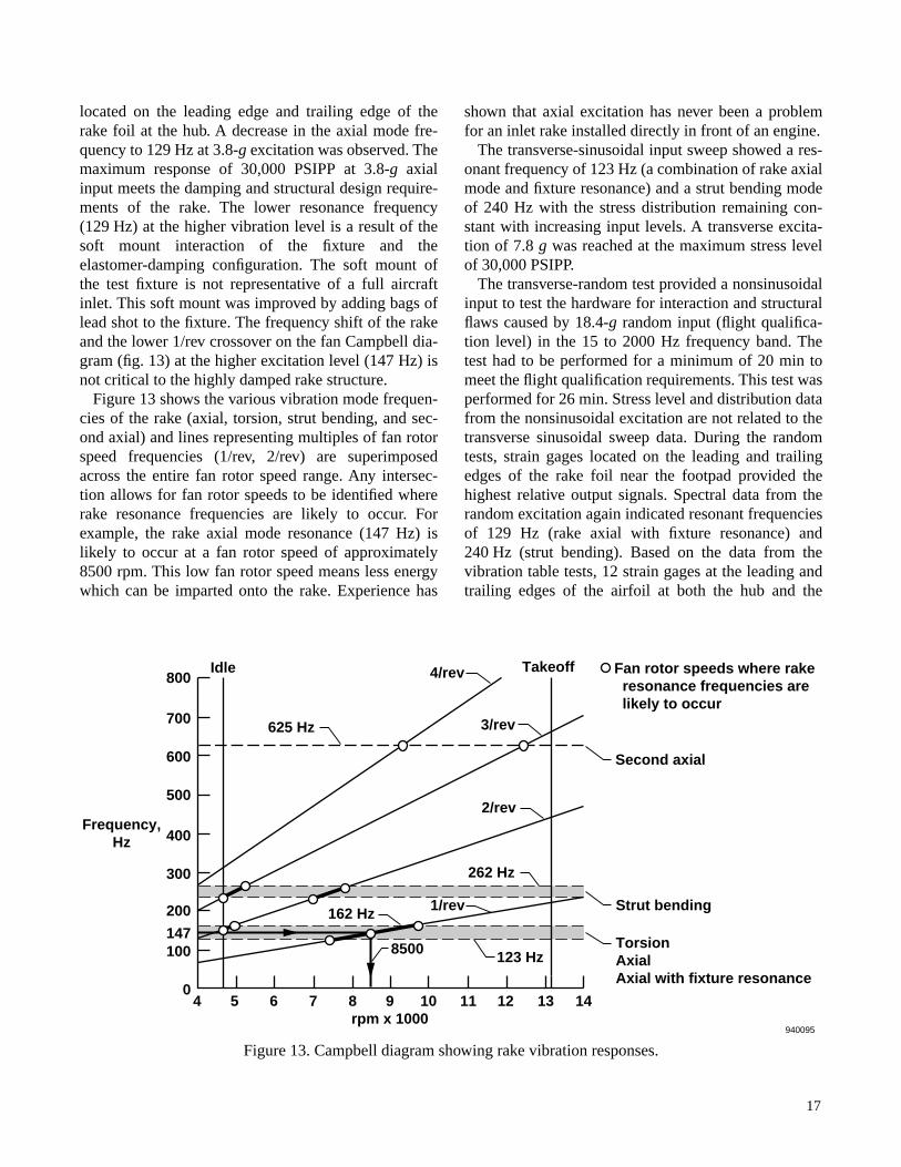
Figure 13 shows the various vibration mode frequen-cies of the rake (axial, torsion, strut bending, and sec-ond axial) and lines representing multiples of fan rotorspeed frequencies (1/rev, 2/rev) are superimposedacross the entire fan rotor speed range. Any intersec-tion allows for fan rotor speeds to be identified whererake resonance frequencies are likely to occur. Forexample, the rake axial mode resonance (147 Hz) islikely to occur at a fan rotor speed of approximately8500 rpm. This low fan rotor speed means less energywhich can be imparted onto the rake. Experience has
shown that axial excitation has never been a problemfor an inlet rake installed directly in front of an engine.
The transverse-sinusoidal input sweep showed a res-onant frequency of 123 Hz (a combination of rake axialmode and fixture resonance) and a strut bending modeof 240 Hz with the stress distribution remaining con-stant with increasing input levels. A transverse excita-tion of 7.8 g was reached at the maximum stress levelof 30,000 PSIPP.
The transverse-random test provided a nonsinusoidalinput to test the hardware for interaction and structuralflaws caused by 18.4-g random input (flight qualifica-tion level) in the 15 to 2000 Hz frequency band. Thetest had to be performed for a minimum of 20 min tomeet the flight qualification requirements. This test wasperformed for 26 min. Stress level and distribution datafrom the nonsinusoidal excitation are not related to thetransverse sinusoidal sweep data. During the randomtests, strain gages located on the leading and trailingedges of the rake foil near the footpad provided thehighest relative output signals. Spectral data from therandom excitation again indicated resonant frequenciesof 129 Hz (rake axial with fixture resonance) and240 Hz (strut bending). Based on the data from thevibration table tests, 12 strain gages at the leading andtrailing edges of the airfoil at both the hub and the
Idle Takeoff Fan rotor speeds where rake resonance frequencies are likely to occur
1/rev
2/rev
3/rev
4/rev
Strut bending
Torsion Axial Axial with fixture resonance
Second axial
625 Hz
262 Hz
123 Hz
162 Hz
940095
10
outer ends of the rake strut were selected to be moni-tored during the ground and flight test program. Thistest resulted in no structural damage to the rake.
Empirical determination of the structural endurancelimit was attempted by exciting the rake at its resonantfrequency at the required 10-g, transverse-sinusoidallevel. The 10-g, transverse excitation showed a stresslevel of 41,000 PSIPP. The 10-g input was to be helduntil the rake structure failed or reached 107 vibrationcycles. The duration would define the endurance limit.The resonant frequency changed from 122 to 117 Hzduring the test. This change probably resulted from theheating effect on modulus of the elastomer pottingmaterial. The 10-g input level was extremely severe onthe inlet test fixture. The test was shut down after 2 hrof dwell time at 10 g to avoid catastrophic damage tothe test fixture. Empirical determination of the rakeendurance limit could not be achieved because thehigh-damping characteristic of the rake made it signifi-cantly more durable than the inlet test fixture. The inlettest fixture could not tolerate excitation levels neces-sary to damage the rake. The rake system showed nosigns of structural damage for the duration of the testand was confirmed with a posttest X-ray and visualinspection of the rake hardware.
The results of the vibration shake table test have beencompared to the NASTRAN computer model predic-tions and to the ping test results. These dynamic analy-sis results are listed next.
The rake vibration testing confirmed the analyticaldesign calculations. The laboratory results from theping and vibration table tests formed the baseline pre-dominant frequencies for comparison to ground andflight testing. A frequency shift limit of ±20 percentwas determined to be reasonable. Shifts greater thanthis limit indicate either a damaged or failed structuralcomponent. The stress limits of 30,000 and
50,000 PSIPP were satisfactory for use during groundand flight testing. Use of these limits depended on thelocation of the strain gage.
Ground Testing
A ping test was performed on the inlet rake installedin the F/A-18 HARV while in the hangar. This test wasused to verify the results gathered during laboratorytesting. Frequencies showed good agreement with thepast laboratory ping test results.
The installed rake was ground tested on the F/A-18HARV with the aircraft tied down. Twelve strain gageswere monitored while the right-hand engine was oper-ated through its full range with a slow accelerationfrom idle power to full maximum afterburning and aslow deceleration to idle power. This procedureallowed predominant frequencies to be identified overthe entire fan rotor speed range. Stress levels and spec-tral data were taken during the test.
The spectra showed predominant frequencies of 153and 162 Hz corresponding to axial and torsional fre-quencies and a broad band about 250 Hz at a lowerlevel corresponding to strut bending modes. These pre-dominant frequencies showed consistent agreementwith the laboratory baseline frequencies. Maximumstress levels during the test were approximately 10 per-cent of limit. Again, the strain gages showing the great-est stresses were located at the leading and trailingedges of the airfoil, at the hub, and at the outer end ofthe rake strut.
Flight Testing
The four most active strain gages were located at theleading and trailing edges of the airfoil, at the hub, andat the outer end of the rake strut, and were selected formonitoring during rake qualification flights. Two weremonitored by telemetry in real time, and two wererecorded on the aircraft for postflight analysis.
Qualification runs for the rake consisted of flightpoints to give maximum unsteady loads (an angle ofattack of 60° at an altitude of 20,000 ft), temperatureand pressure (Mach 0.7 on the deck), and combinationof temperature, pressure, and unsteady loads (Mach 0.9at an altitude of 18,000 ft) within the HARV flightenvelope. The latter two points were at the limits of theHARV flight envelope. The first point was flown to ahigh-angle-of-attack condition. The latter two pointswere obtained at the maximum maneuver-loadinglimit.
ModeNASTRANmodel, Hz
Ping test, Hz
Vibration table, Hz
Axial 140 155 147
Torsion 147 162 N/A
Axial with fixture resonance
N/A N/A 123–129
Strut bending 250 236–262 240
Second axial 594 625 N/A
18
The spectra of the rake vibrations remained consis-tent with the ground and laboratory tests. The stresslevels observed were 26 percent of limits during high-angle-of-attack flight and less than 10 percent of limitsduring maximum maneuver-loading flight. The maxi-mum stress limits observed were 30 percent of limitsduring aircraft takeoff. Based on the laboratory,ground, and flight test results, the rake is now fullycleared for conducting flight research within the entireHARV flight envelope with no restrictions.
CONCLUDING REMARKS
An improved cost and installation-time saving inletdistortion pressure rake was successfully designed,built, and validated for flight testing on the F/A-18HARV research aircraft. The innovative design consistsof a one-piece, wagon wheel approach that resulted inease of installation with minimal aircraft modifications.Design advantages include lightweight, high strength,low structural resonance, low flow blockage, and easytransducer removal and replacement. A prototype ofthe new rake was environmentally tested in a labora-tory where it passed all vibration structural require-ments. Ground test verified the expected frequencyresponse predicted from laboratory test. Flight qualifi-cation was completed and the rake is now cleared forflight testing on the HARV aircraft. All stress levelsobserved during ground and flight qualification wereless then 30 percent of limits.
The simple design approach and creative use of light-weight materials such as elastomers resulted in a supe-rior rake design at a significantly lower cost than previ-ous design approaches. The rake has promise of ease oftransportability to other F404-GE-400 equipped air-craft. Further design efforts are expected to allow the
design flight envelope to be expanded to supersonicconditions and allow scaling to other aircraft inlets.The cost and time saving solution to the inlet rakedesign will allow the F/A-18 HARV to conductimportant inlet research at flight conditions neverbefore explored.
ACKNOWLEDGMENT
The DFRC, LeRC, and GEAE team members wish torecognize posthumously the creative energy brought byco-author Leon Lechtenberg to this project. It is unfor-tunate that his tragic and untimely death did not allowhim to see the fruit of his labor that resulted in success-ful ground and flight clearance of this novel rakedesign.
REFERENCES
1Amin, N.F. and D.J. Hollweger, “F/A-18A Inlet/EngineCompatibility Flight Test Results,” AIAA-81-1393,July, 1981.
2Inlet Total-Pressure-Distortion Considerations for Gas-Turbine Engines, Society of Automotive EngineersAerospace Information Report, AIR 1419, May 1983.
3Gas Turbine Engine Inlet Flow Distortion Guidelines,Society of Automotive Engineers Aerospace Recom-mendedPractice, ARP 1420, Mar. 1978.
4Holzman, Jon K. and Gordon A. Payne, Design and FlightTesting of a Nullable Compressor Face Rake, NASA TND-7162, Jan. 1973.
5Farr, A.P. and G.A. Schumacher, “System For Evaluationof F-15 Inlet Dynamic Distortion,” Symposium onInstrumentation for Airbreathing Propulsion, MCAIR72-043, Sept. 1972.
19
REPORT DOCUMENTATION PAGE Form ApprovedOMB No. 0704-0188
Public reporting burden for this collection of information is estimated to average 1 hour per response, including the time for reviewing instructions, searching existing data sources, gathering and maintaining the data needed, and completing and reviewing the collection of information. Send comments regarding this burden estimate or any other aspect of this collection of information, including suggestions for reducing this burden, to Washington Headquarters Services, Directorate for Information Operations and Reports, 1215 Jefferson Davis Highway, Suite 1204, Arlington, VA 22202-4302, and to the Office of Management and Budget, Paperwork Reduction Project (0704-0188), Washington, DC 20503.
1. AGENCY USE ONLY (Leave blank) 2. REPORT DATE 3. REPORT TYPE AND DATES COVERED
4. TITLE AND SUBTITLE 5. FUNDING NUMBERS
6. AUTHOR(S)
8. PERFORMING ORGANIZATION REPORT NUMBER
7. PERFORMING ORGANIZATION NAME(S) AND ADDRESS(ES)
9. SPONSORING/MONOTORING AGENCY NAME(S) AND ADDRESS(ES) 10. SPONSORING/MONITORING AGENCY REPORT NUMBER
11. SUPPLEMENTARY NOTES
12a. DISTRIBUTION/AVAILABILITY STATEMENT 12b. DISTRIBUTION CODE
13. ABSTRACT (Maximum 200 words)
14. SUBJECT TERMS 15. NUMBER OF PAGES
16. PRICE CODE
17. SECURITY CLASSIFICATION OF REPORT
18. SECURITY CLASSIFICATION OF THIS PAGE
19. SECURITY CLASSIFICATION OF ABSTRACT
20. LIMITATION OF ABSTRACT
NSN 7540-01-280-5500 Standard Form 298 (Rev. 2-89)Prescribed by ANSI Std. Z39-18298-102
Design and Development of an F/A-18 Inlet Distortion Rake: A Cost andTime Saving Solution
WU 505-68
Andrew J. Yuhas, Ronald J. Ray, Richard R. Burley, William G. Steenken,Leon Lechtenberg, and Don Thornton
NASA Dryden Flight Research CenterP.O. Box 273Edwards, California 93523-0273
H-2078
National Aeronautics and Space AdministrationWashington, DC 20546-0001 NASA TM-4722
An innovative inlet total-pressure-distortion measurement rake has been designed and developed for theF/A-18 A/B/C/D aircraft inlet. The design was conceived by NASA and General Electric Aircraft Enginespersonnel. This rake has been flight qualified and flown in the F/A-18 High Alpha Research Vehicle at NASADryden Flight Research Center, Edwards, California. The eight-legged, one-piece, wagon wheel design of therake was developed at a reduced cost and offered reduced installation time compared to traditional designs.The rake features 40 dual-measurement ports for low- and high-frequency pressure measurements with thehigh-frequency transducer mounted at the port. This high-frequency transducer offers direct absolute pressuremeasurements from low to high frequencies of interest, thereby allowing the rake to be used during highlydynamic aircraft maneuvers. Outstanding structural characteristics are inherent to the design through itsconstruction and use of lightweight materials.
Available from the NASA Center for AeroSpace Information, 800 Elkridge Landing Road, Linthicum Heights, MD 21090; (301)621-0390
Presented as AIAA 94-2132 at the 7th Biennial AIAA Flight Test Conference, Colorado Springs, Colorado, June 20–23, 1994. A.J. Yuhas, PRC Inc.,Edwards, California; R.J. Ray, Dryden Flight Research Center, Edwards, California; R.R. Burley, NASA Lewis Research Center, Cleveland, Ohio;W.G. Steenken, L. Lechtenberg, and D. Thornton, General Electric Aircraft Engines, Evendale, Ohio.