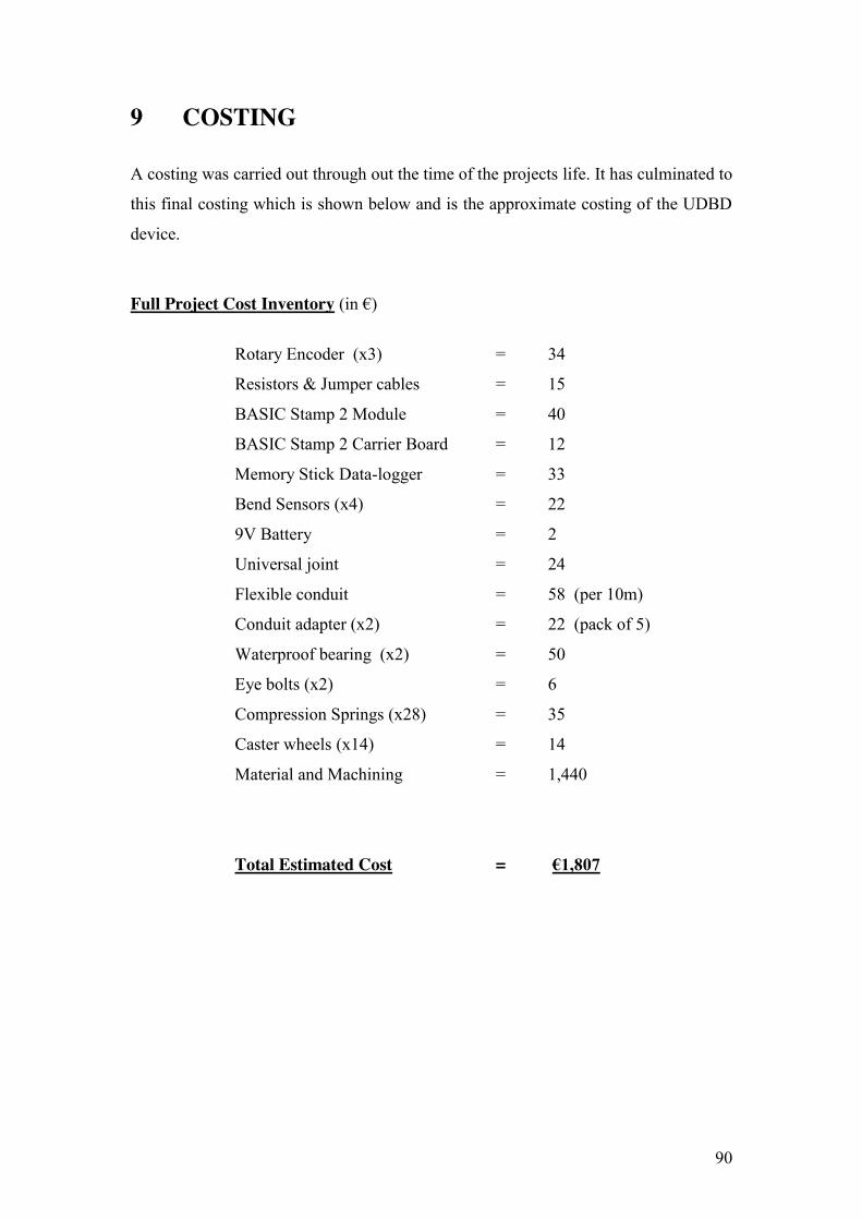
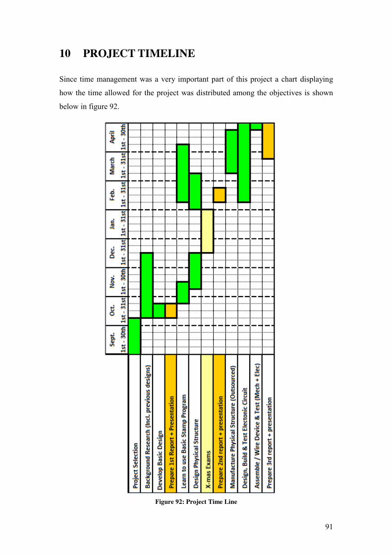
Final Year Project for B.Eng (Hons) in Mechanical Engineering at the Dublin Institute of Technology, Bolton St, Ireland. Carried out from October to April, 2010.
Department of Mechanical Engineering The Design of an Underground Duct Bend Detector Student Name: Robin Maguire Course: DT022/4 Mechanical Engineering Student number: C05509734 Project Tutor: Graham Gavin Submitted: May 2010
Transcript
Department of Mechanical Engineering
The Design of an Underground Duct Bend Detector
Student Name: Robin Maguire
Course: DT022/4 Mechanical Engineering
Student number: C05509734
Project Tutor: Graham Gavin
Submitted: May 2010
DECLARATION I herby confirm that all of the following content in this project report is my own unless otherwise indicated. Signed (Candidate) k Date 0
2
ACKNOWLEDGEMENTS I wish to acknowledge and thank my project tutor Dr. Graham Gavin (DIT Bolton St.)
for his guidance, encouragement and support throughout the project.
I would like to acknowledge ESB Networks who provided me with the opportunity to
undertake this project and for the associated funding.
A special word of thanks is due to Mr. Tom Looby who provided me with details of
the brief for the device and also all his invaluable advice and support at all stages
throughout the project.
Dr. Robert Simpson (Head of School for Mechanical and Transport Engineering, DIT
Bolton St.) also provided practical support and encouragement.
I wish to also acknowledge Mr. Cecil Potterton (Linen Hall) whom I consulted with
for advice on the welding specifications for the device.
Mr. Mark Hederman from Hederman Engineering did an excellent job taking the
design brief and manufacturing and customizing the parts for the device.
Finally I would like to thank my family and friends for their encouragement and
unwavering support throughout the duration of this project.
I - ELECTRONIC COMPONENT SPECIFICATIONS .................................... 99
II - MECHANICAL COMPONENT SPECIFICATIONS ............................... 106
II - DRAWINGS ............................................................................................... 117
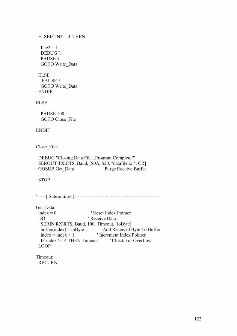
III - PROGRAM CODE .................................................................................... 118
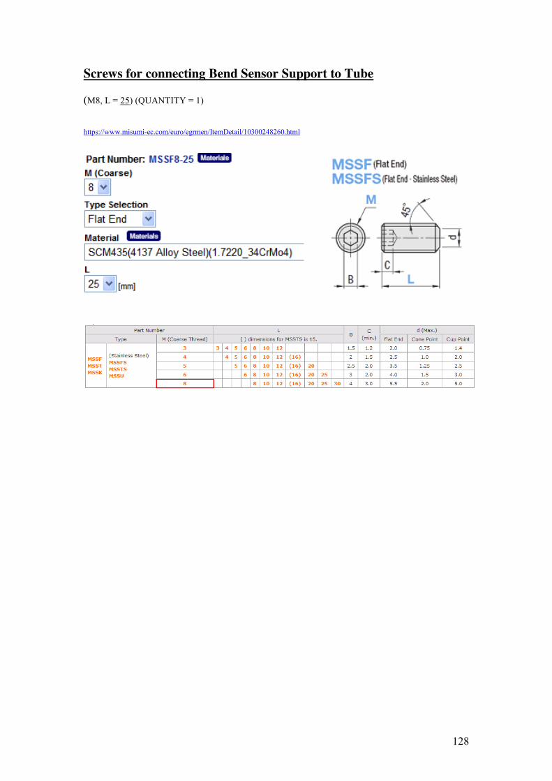
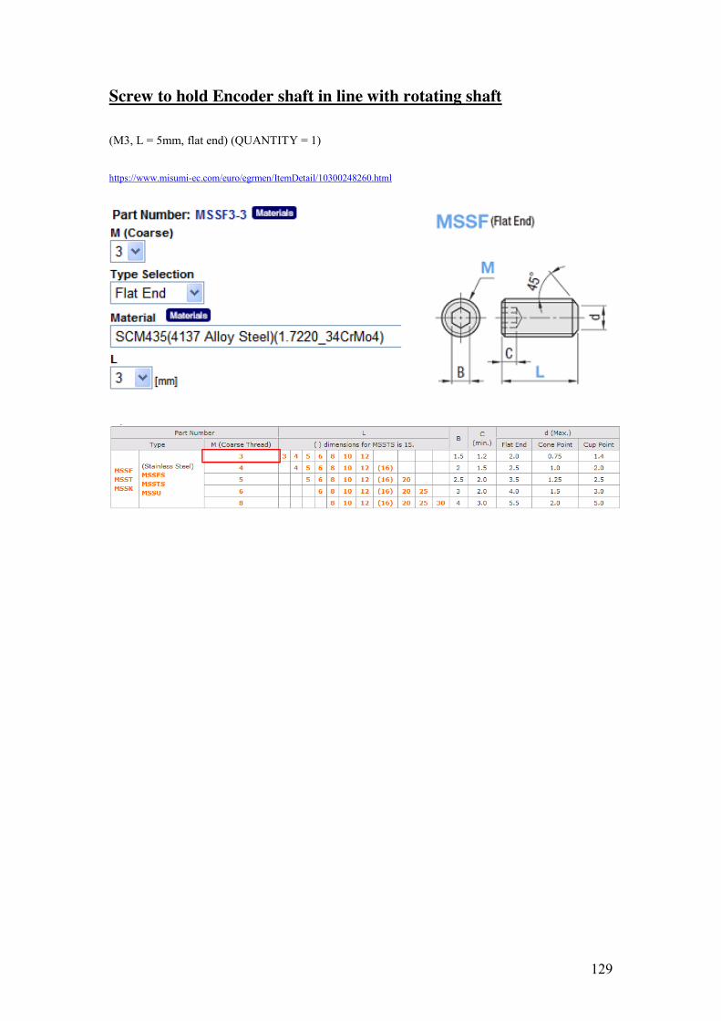
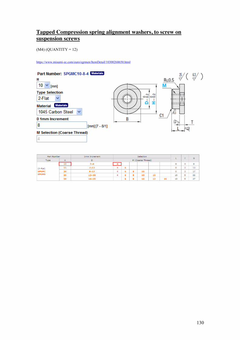
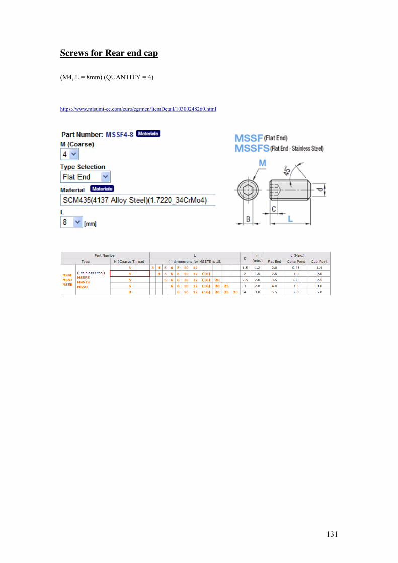
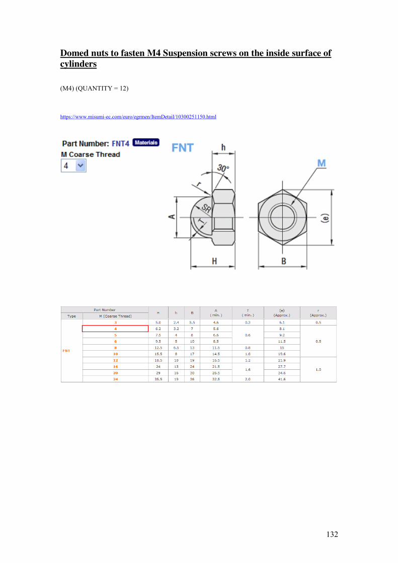
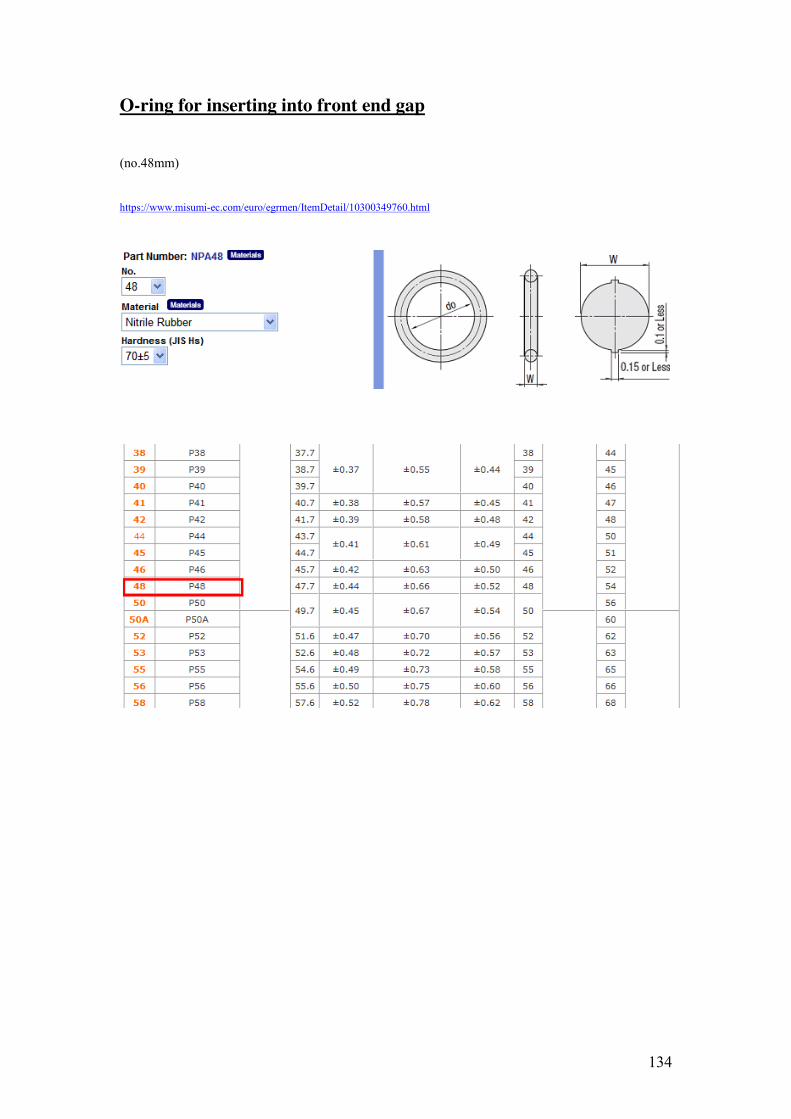
IV – FASTENER & MISCELLANEOUS SPECIFICATIONS ....................... 123
5
LIST OF FIGURES Figure 1: Cable Pulling Tension Formulae [1] ........................................................................ 10 Figure 2: Cable pulling Example [1] ........................................................................................ 10 Figure 3: Standard ESB Duct [1] ............................................................................................. 11 Figure 4: Previous UDBD and associated equipment [1] ........................................................ 12 Figure 5: Working drawing of previous UDBD [1] ................................................................. 12 Figure 6: Side view of Bend Detector for a Pipeline Pig [3] ................................................... 14 Figure 7: Incremented graph paper for Bend Detector for a Pipeline Pig [3] .......................... 14 Figure 8: Side view and side section view of Pipeline Verification Pig [4] ............................ 15 Figure 9: Graphical indication of feeler arm deflection [4] ..................................................... 15 Figure 10: Side view of Bend Detector Pig [5] ........................................................................ 16 Figure 11: Front elevation section view of feeler a [5] ............................................................ 16 Figure 12: Side views of Pipeline Bend Detector Pig [6] ........................................................ 17 Figure 13: Split side section view of Pipeline Bend Detector Pig [6] ..................................... 17 Figure 14: Examples of Envirosight Designs [7] ..................................................................... 18 Figure 15: Examples of Reduct Designs [8] ............................................................................ 18 Figure 16: Client’s Requirements: Rating Questionnaire ........................................................ 20 Figure 17: IP - Legend for 1st Digit in Code [9] ..................................................................... 22 Figure 18: IP – Legend for 2nd Digit in Code [9].................................................................... 23 Figure 19: Nominal Pipe Size Standard Schedules [10] .......................................................... 23 Figure 20: Mechanical Pot alongside Bend Sensor [11] .......................................................... 25 Figure 21: Rotary Encoder [12] ............................................................................................... 27 Figure 22: Basic Stamp 2 Module [13] .................................................................................... 28 Figure 23: Thermal Accelerometer [16] .................................................................................. 29 Figure 24: Data Logger [17] .................................................................................................... 30 Figure 25: Objectives Tree ....................................................................................................... 36 Figure 26: FAM Diagram ........................................................................................................ 38 Figure 27: Quality Function Deployment Matrix .................................................................... 40 Figure 28: Design concept for UDBD [1] ................................................................................ 41 Figure 29: Foundation Design for Electronic Circuit .............................................................. 42 Figure 30: Front Section Design Sketch .................................................................................. 44 Figure 31: Middle Section Design Sketch ............................................................................... 45 Figure 32: Rear Section Design Sketch ................................................................................... 46 Figure 33: Wheels and Suspension System Sketch 1............................................................... 46 Figure 34: Wheels and Suspension System Sketch 2............................................................... 47 Figure 35: Wheels and Suspension System Sketch 3............................................................... 48 Figure 36: Universal Joint [18] ................................................................................................ 48 Figure 37: Waterproof Bearing [19] ........................................................................................ 49 Figure 38: Lifting Eye Bolt [20] .............................................................................................. 49 Figure 39: Compression Spring [21] ........................................................................................ 49 Figure 40: Castor Wheel [22]................................................................................................... 50 Figure 41: Flexible Conduit + Adapter [23] ............................................................................ 50 Figure 42: 3D Solid Models for Front Section ........................................................................ 51 Figure 43: 3D Solid Models for Middle Section ...................................................................... 52 Figure 44: 3D Solid Models for Rear Section .......................................................................... 53 Figure 45: 3D Solid Models for Wheels Support in Rear Section ........................................... 53
6
Figure 46: 3D Solid Models for Wheel and Suspension System ............................................. 54 Figure 47: View of Assembled 3D Solid Models .................................................................... 55 Figure 48: Redesigned Front End Cap ..................................................................................... 58 Figure 49: Redesigned Assembly of (F & R) Cylinders, Weld Caps and (F & R) Tubes ....... 58 Figure 50: Redesigned Assembly of Weld Caps and (F & R) Tubes ...................................... 60 Figure 51: Redesigned Rear Tube and Inclusion of Bend Sensor Support .............................. 60 Figure 52: Redesign of Odometer Wheel Support System ...................................................... 61 Figure 53: Photos of some of the Wheels support system parts .............................................. 62 Figure 54: Redesign of Wheel and Shaft ................................................................................. 62 Figure 55: Redesigned Rear End Cap ...................................................................................... 63 Figure 56: Assembly and Exploded Views and Parts List ....................................................... 64 Figure 57: Photo of Assembled Mechanical Structure ............................................................ 65 Figure 58: Front Section of Assembled Mechanical Structure ................................................ 65 Figure 59: Rear Section of Assembled Mechanical Structure ................................................. 65 Figure 60: Testing of Mechanical Structure without Conduit ................................................. 66 Figure 61: Testing of Mechanical Structure with Conduit ....................................................... 67 Figure 62: Switch configuration without debouncing circuit [24] ........................................... 68 Figure 63: Behavior of a switch without a denouncing circuit [24] ........................................ 69 Figure 64: Switch configuration with debouncing circuit [24] ................................................ 70 Figure 65: Behavior of a switch with a debouncing circuit [24] .............................................. 70 Figure 66: Switch configuration with debounce circuit and Schmitt Trigger [24] .................. 71 Figure 67: Switch configuration with debounce circuit and Schmitt Trigger .......................... 71 Figure 68: Built debounce circuit, testing and results .............................................................. 72 Figure 69: Example of very high levels of bounce in a switch ................................................ 72 Figure 70: 4-Bit Dec. Counters interaction with circuit ........................................................... 73 Figure 71: Circuit Diagram of debounced Encoder and Dec. Counter .................................... 74 Figure 72: Latest circuit constructed on breadboard ................................................................ 74 Figure 73: Construction of debounced circuit including Dec. Counter ................................... 75 Figure 74: Testing the debounced circuit including the Dec. Counter..................................... 75 Figure 75: Wiring plan of proposed design for circuit containing remaining electronics ....... 77 Figure 76: Downloading Program code and Testing Circuit ................................................... 78 Figure 77: Observing Microprocessor in test on Debug Terminal........................................... 79 Figure 78: Redesigned layout for electronic circuit ................................................................. 80 Figure 79: Strip-board prepared for soldering ......................................................................... 81 Figure 80: Completed Redesigned Electronic Circuit ............................................................. 81 Figure 81: Integration of Rotary Encoder into UDBD............................................................. 82 Figure 82: Integration of Bend Sensors into UDBD ................................................................ 83 Figure 83: Integration of the Electronic Circuit based on Strip-board into UDBD ................. 83 Figure 84: Completed UDBD (with conduit removed)............................................................ 84 Figure 85: Opened Data-File ................................................................................................... 85 Figure 86: Data-file converted to Excel ................................................................................... 86 Figure 87: Information Processing File before input of data ................................................... 87 Figure 88: Cell C2 and function ............................................................................................... 87 Figure 89: Cell D2 and function .............................................................................................. 88 Figure 90: Information Processing File after input of data ...................................................... 88 Figure 91: Information Processing File after Graph has been plotted ..................................... 89 Figure 92: Project Time Line ................................................................................................... 91
7
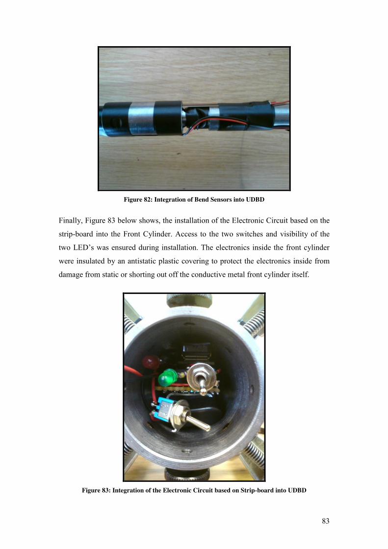
ABSTRACT
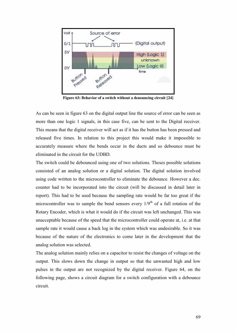
Author: Robin Maguire Title: Design of an Underground Duct Bend Detector (UDBD) The aim of this project was “to develop the current design concept for UDBD, both
electronically and mechanically, which can then be manufactured, tested and handed
over to the ESB”. This was achieved through the completion of five main objectives,
listed below.
1. Research into any topics/subjects and designs relevant to this project
2. Develop a foundation design based on research carried out
3. Design, Build & Test the Mechanical Device
4. Design, Build & Test the Electronic Circuit
5. Test the completed Device
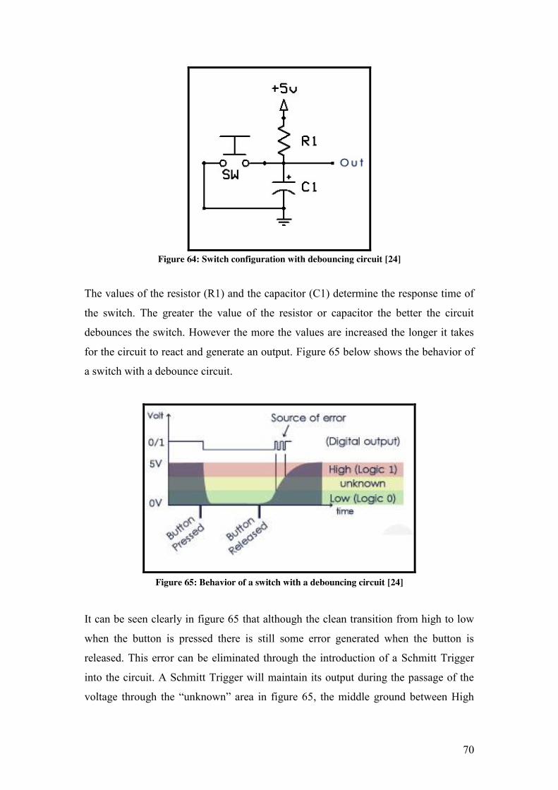
The methodology used for the project was based on the sub-objectives required to
complete the five main objectives listed above.
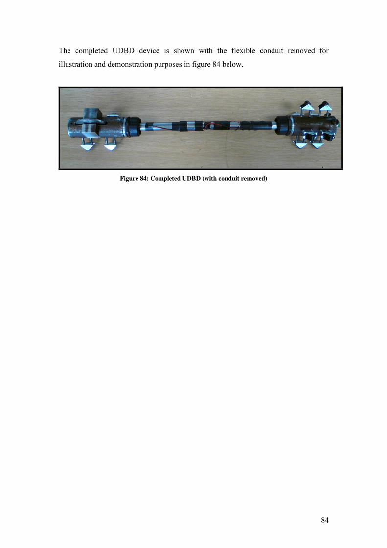
The device was designed, manufactured and tested. Microsoft Excel was used to
process the data which was collected by the device during testing. An Excel file was
designed to process this information so that it could display the results graphically.
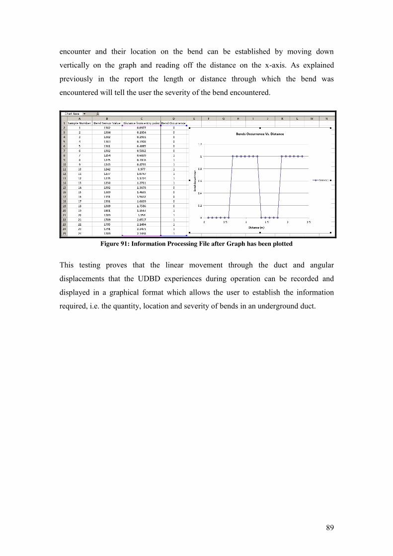
The testing proved that the device could detect the quantity, location and severity of
bends in underground ducting and display this data in a quick and clear way after use.
The UDBD was a success and this was evident from the results of the testing carried
out.
8
1 INTRODUCTION
The Electricity Supply Board (ESB) lays underground ducts for their high voltage
cables. They commonly encounter other underground services in their path when
laying the ducts and these must be avoided. To avoid these they incorporate bends
into the ducting’s path. The quantity, location and severity of these bends directly
effects the tension required to pull the cable through the ducting, i.e. the more bends
closer to the pulled end of the duct and the greater their severity, the greater the
pulling tension required. Therefore, being able to establish this information before
choosing the location/s along the duct or the end at which to pull the cable through is
of great importance to the ESB. Currently this information is unattainable and the
cable tension is not calculated properly. This makes pulling the cables a very risky
operation since the cables and/or ducting can be damaged and can cost the ESB
significantly, with regards to safety, time and money.
A solution to this problem was started last year by a Dublin Institute of Technology
(DIT), Bolton St. student, who came up with the design concept that allowed the user
to determine the number of bends, their severity and their locations along a length of
ducting. However this development only went as far as producing a very basic
prototype, restricted to Laboratory use, to prove the design concept would work,
which it did.
This project will take up where the previous student’s project left off. The design
concept has already been proven successful so it can now be developed further into an
end product for ESB Networks to use. This will involve designing a mechanical
device for use in the demanding working environment of an outdoor site. It will also
involve the design of an electronic system housed inside the device, to detect record
and store information relating to the quantity, location and severity of bends in
underground ducting.
9
2 PROJECT AIMS AND OBJECTIVES
Aim To develop the current design concept for UDBD, both electronically and
mechanically, which can then be manufactured, tested and handed over to the ESB
Objectives
1. Research into any topics/subjects and designs relevant to this project
2. Develop a foundation design based on research carried out
3. Design, build & test the Mechanical Device
4. Design, build & test the Electronic Circuit
5. Test the completed Device
10
3 BACKGROUND RESEARCH
3.1 Cable Pulling
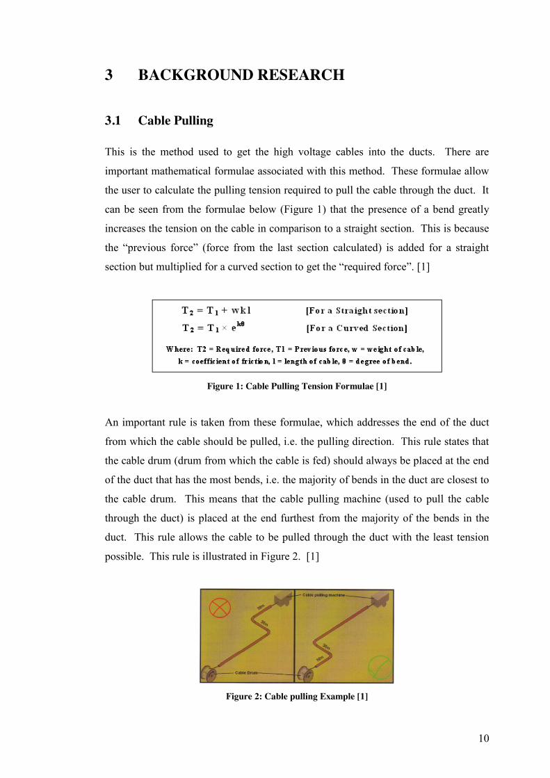
This is the method used to get the high voltage cables into the ducts. There are
important mathematical formulae associated with this method. These formulae allow
the user to calculate the pulling tension required to pull the cable through the duct. It
can be seen from the formulae below (Figure 1) that the presence of a bend greatly
increases the tension on the cable in comparison to a straight section. This is because
the “previous force” (force from the last section calculated) is added for a straight
section but multiplied for a curved section to get the “required force”. [1]
Figure 1: Cable Pulling Tension Formulae [1]
An important rule is taken from these formulae, which addresses the end of the duct
from which the cable should be pulled, i.e. the pulling direction. This rule states that
the cable drum (drum from which the cable is fed) should always be placed at the end
of the duct that has the most bends, i.e. the majority of bends in the duct are closest to
the cable drum. This means that the cable pulling machine (used to pull the cable
through the duct) is placed at the end furthest from the majority of the bends in the
duct. This rule allows the cable to be pulled through the duct with the least tension
possible. This rule is illustrated in Figure 2. [1]
Figure 2: Cable pulling Example [1]
11
3.2 ESB Ducts
Ducts are used by the ESB to protect their high voltage cables whilst underground
(shown in Figure 3 below). The particular type of duct that the ESB use to house their
high voltage cables is of great importance because it will influence the materials
selected during the design process later in the project. These particular ducts are
made of high density polyethylene (HDPE) [1]. A few characteristics of HDPE are
shown below [2]. HDPE Characteristics MIGHT BE BETTER GETTING MORE RELEVANT ONES
Maximum Temperature: 120°C
Minimum Temperature: -100°C
Melting point: 130°C
Tensile Strength: 31.4 MN
Figure 3: Standard ESB Duct [1]
The dimensions of the ducts are also very important as they will dictate the
dimensions of the device which will have to be able to fit inside the duct. The ducting
has an outer diameter of 125mm and an internal diameter of 117mm leaving a wall
thickness of 4mm. The ducts are certified to absorb impacts and deflection forces in
order to protect the cables within.
There are five different shape variances in the ducting, a straight duct section and four
different bend sections. All of these bends have a 1.2 meter radius; however their
angle and length vary. The axial length of the bend determines its angle. The
measurements for the different bend sections are shown below. [1]
Bend Specifications
Angle (degrees)
90
45
22
11.5
Radius (m)
1.2
1.2
1.2
1.2
Approx. Length (m)
1.8
0.9
0.5
0.2
12
3.3 Existing Designs
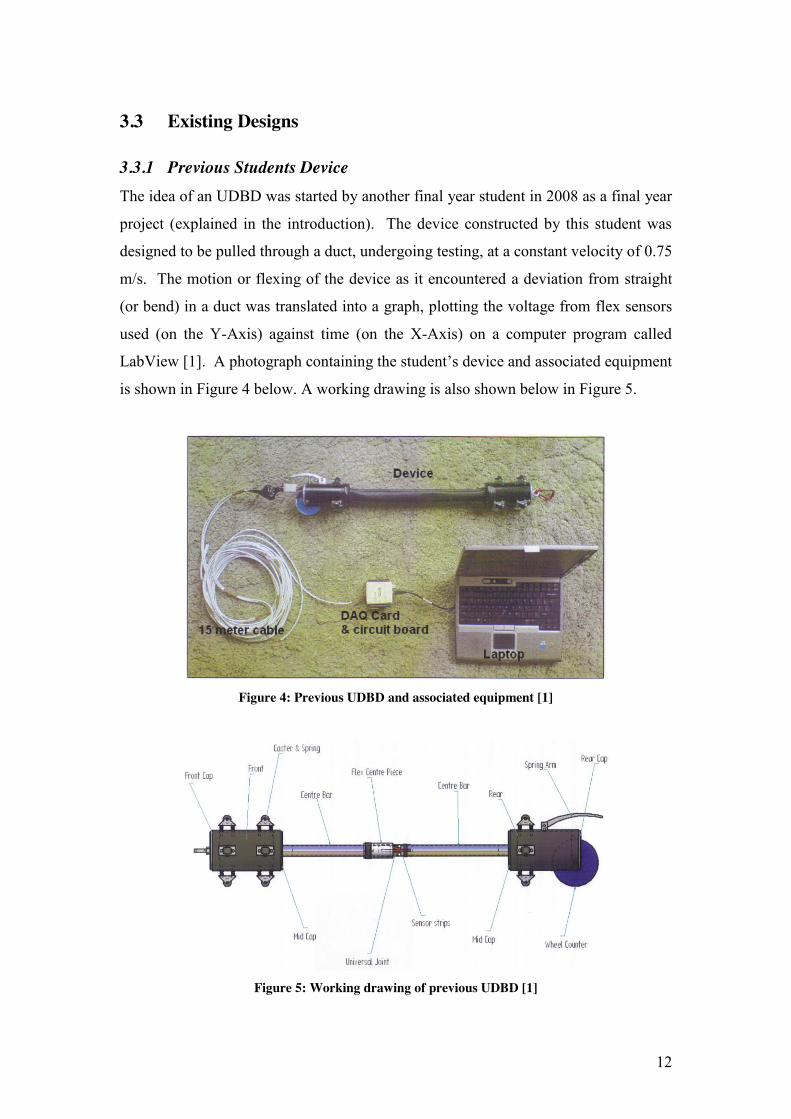
3.3.1 Previous Students Device The idea of an UDBD was started by another final year student in 2008 as a final year
project (explained in the introduction). The device constructed by this student was
designed to be pulled through a duct, undergoing testing, at a constant velocity of 0.75
m/s. The motion or flexing of the device as it encountered a deviation from straight
(or bend) in a duct was translated into a graph, plotting the voltage from flex sensors
used (on the Y-Axis) against time (on the X-Axis) on a computer program called
LabView [1]. A photograph containing the student’s device and associated equipment
is shown in Figure 4 below. A working drawing is also shown below in Figure 5.
Figure 4: Previous UDBD and associated equipment [1]
Figure 5: Working drawing of previous UDBD [1]
13
This student’s project is the basis for this final year project. A brief analysis of the
previous student’s project was important to ensure as much background information
as possible was gathered. The analysis was broken down into positives and negatives
and follows on below.
Positives
1 - The design concept for this underground duct bend detector is excellent because it
solved the problem that the ESB have. It is capable of gathering all of the duct
information that they require.
2 - Evidence that the design concept works was established by the student through
successfully testing of the prototype from the project, thus proving the claims
made about the underground duct bend detector.
3 - The information that the previous project contains is obviously of direct relevance
to this project, so it has provided a kick start to the research for this project.
Negatives:
1 - The prototype that the student produced required a wire connection to a computer
running a software program called LabView, which was used to store and view
the information that that the underground bend detector collected. This obviously
restricted the use of the student’s design to lab testing, as it would not be suitable
or practical for the ESB to use on site.
2- The prototype was only designed for the conditions found in a lab environment. It
was not designed for dust/dirt, rain or any kind of rough treatment during use, like
the general wear and tear that other equipment used on site by the ESB would
have to contend with.
3 - The student appeared to focus on the proof of the design concept, as opposed to
creating an in depth design, taking into account cost, durability, reliability, safety
and other important factors.
14
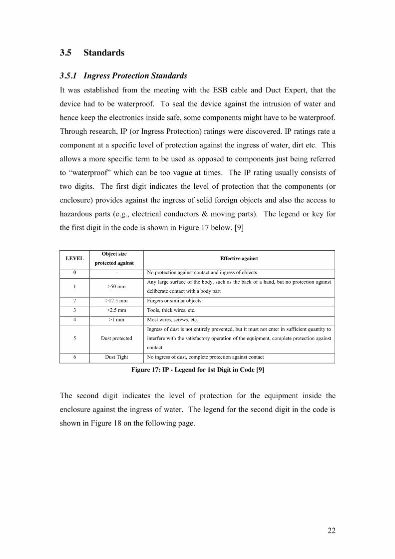
3.3.2 Patents To ensure the finished design is as effective as possible, a further investigation into
existing designs was undertaken. This allows the designer to gain a greater depth into
what advances have already been made and an opportunity to scrutinize other designs
with regard to their improvement. Four Patents were found relating to this project
ranging from 1986 to 1993. They are briefly explained below.
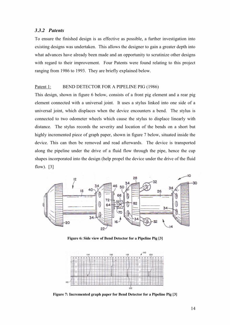
Patent 1: BEND DETECTOR FOR A PIPELINE PIG (1986)
This design, shown in figure 6 below, consists of a front pig element and a rear pig
element connected with a universal joint. It uses a stylus linked into one side of a
universal joint, which displaces when the device encounters a bend. The stylus is
connected to two odometer wheels which cause the stylus to displace linearly with
distance. The stylus records the severity and location of the bends on a short but
highly incremented piece of graph paper, shown in figure 7 below, situated inside the
device. This can then be removed and read afterwards. The device is transported
along the pipeline under the drive of a fluid flow through the pipe, hence the cup
shapes incorporated into the design (help propel the device under the drive of the fluid
flow). [3]
Figure 6: Side view of Bend Detector for a Pipeline Pig [3]
Figure 7: Incremented graph paper for Bend Detector for a Pipeline Pig [3]
15
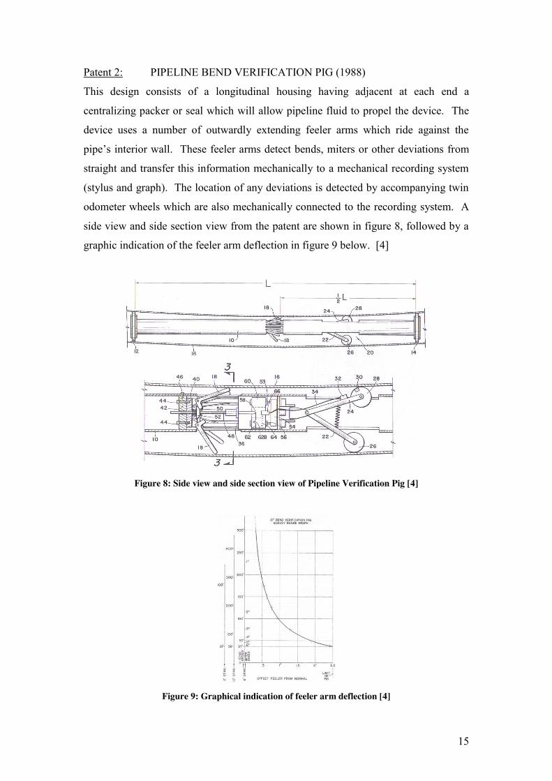
Patent 2: PIPELINE BEND VERIFICATION PIG (1988)
This design consists of a longitudinal housing having adjacent at each end a
centralizing packer or seal which will allow pipeline fluid to propel the device. The
device uses a number of outwardly extending feeler arms which ride against the
pipe’s interior wall. These feeler arms detect bends, miters or other deviations from
straight and transfer this information mechanically to a mechanical recording system
(stylus and graph). The location of any deviations is detected by accompanying twin
odometer wheels which are also mechanically connected to the recording system. A
side view and side section view from the patent are shown in figure 8, followed by a
graphic indication of the feeler arm deflection in figure 9 below. [4]
Figure 8: Side view and side section view of Pipeline Verification Pig [4]
Figure 9: Graphical indication of feeler arm deflection [4]
16
Patent 3: BEND DETECTOR PIG (1990)
This design, shown in figure 9 below, is very similar to the first design patent
discussed in this section. However it uses a shorter rear section and the mechanical
system used to detect and record the deviations in the pipe varies. This design uses
feeler arms, illustrated in figure 11 below; much like the previous design discussed
but houses them differently. It uses permanent magnets thereon, which activate a read
switch for the odometers situated on either side of the housing. This is similar to the
mechanism used to detect and record bends in this project’s design, only a rotary
encoder is used instead. It is also propelled by a fluid flow through a pipe and also
utilizes cup shaped front end and middle sections to aid this propulsion. [5]
Figure 10: Side view of Bend Detector Pig [5]
Figure 11: Front elevation section view of feeler a [5]
17
Patent 4: PIPELINE BEND DETECTOR PIG (1993)
This final design, shown in figure 12 below, is the only one to utilize electronic
components in its design. The design incorporates potentiometers much the same as
this project intends to incorporate them. The mechanism also uses solid state memory
for recording purposes in a similar manner to this project, however on a much more
basic level when compared with this project. This design incorporates a battery as a
power source which is what this project will most likely use as its power source. This
device is mainly made of urethane. It uses an azimuth signal generator to indicate the
orientation of the device in relation to vertical. A split side section view of the patent
design is shown below in figure 13. [6]
Figure 12: Side views of Pipeline Bend Detector Pig [6]
Figure 13: Split side section view of Pipeline Bend Detector Pig [6]
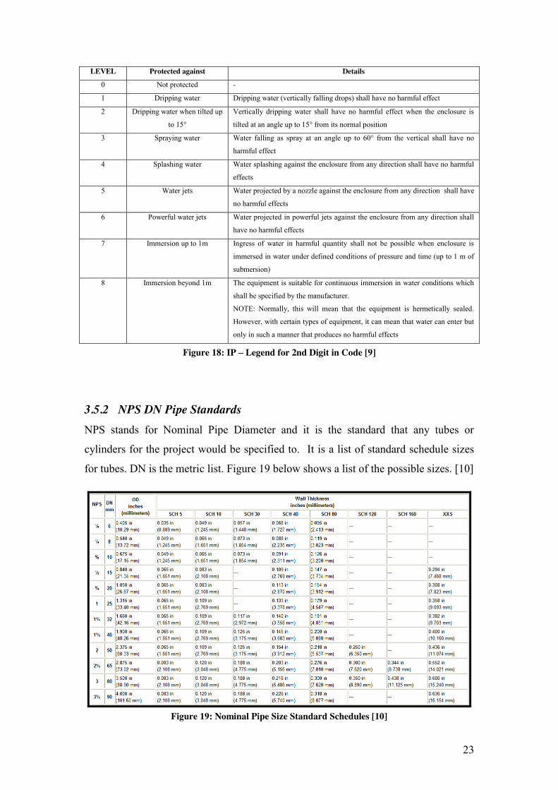
18
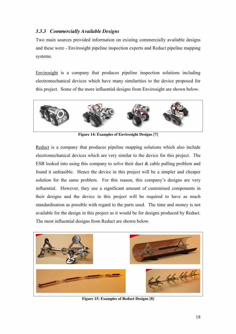
3.3.3 Commercially Available Designs Two main sources provided information on existing commercially available designs
and these were - Envirosight pipeline inspection experts and Reduct pipeline mapping
systems.
Envirosight is a company that produces pipeline inspection solutions including
electromechanical devices which have many similarities to the device proposed for
this project. Some of the more influential designs from Envirosight are shown below.
Figure 14: Examples of Envirosight Designs [7]
Reduct is a company that produces pipeline mapping solutions which also include
electromechanical devices which are very similar to the device for this project. The
ESB looked into using this company to solve their duct & cable pulling problem and
found it unfeasible. Hence the device in this project will be a simpler and cheaper
solution for the same problem. For this reason, this company’s designs are very
influential. However, they use a significant amount of customised components in
their designs and the device in this project will be required to have as much
standardisation as possible with regard to the parts used. The time and money is not
available for the design in this project as it would be for designs produced by Reduct.
The most influential designs from Reduct are shown below.
Figure 15: Examples of Reduct Designs [8]
19
3.4 Investigation into UDBD Requirements
The only information relating to the needs or requirements of the client (ESB
Networks) for this project was some second hand information from Graham Gavin
(Project Tutor) and whatever could be taken from the previous student’s final project
report. This was not enough information to ensure the success of the project. A
meeting with a cable and duct expert in ESB Networks was organized to obtain more
information. A questionnaire was prepared before the interview took place. It
contains various questions regarding the attributes and characteristics that the ESB
Networks wanted the device to satisfy. The questionnaire is shown below in (figure
16) and the ratings themselves are shown in red.
Client’s Requirements: Rating Questionnaire The information received through the completion of this from will help the designer create a device
which can satisfy as many of the client’s design requirements as possible.
The task is explained below:
1. Rate each of the following attributes and characteristics with a number between 0 and 9 (9 being
the most important, 1 the least important and 0 being totally unimportant and unnecessary). If any
attributes or characteristics absolutely must be satisfied in the design, mark them with an “*” and do not rate them between 0 and 9.
Device Attributes and Characteristics:
Withstand forces (from being dropped, crushed, pulled etc.) Out of 10 → [8]
Withstand water/dirt (from exposure to, or being, submerged in water / dirt) Out of 10 → [*]
Low maintenance (designed to require as little maintenance as possible) Out of 10 → [*]
Easy maintenance (designed to be as easy to maintain as possible) Out of 10 → [*]
Light (weighing as little as possible) Out of 10 → [3]
Small (as small in size as possible) Out of 10 → [4]
Easy to attach (to cord for pulling through duct on either side of device) Out of 10 → [6]
20
Easy to detach (from cord on either side of device) Out of 10 → [6]
Easy to handle (ergonomics etc.) Out of 10 → [3]
Easy access to info. stored in Device (USB key) Out of 10 → [*]
Safe (device will not have any risk of injury to user) Out of 10 → [*]
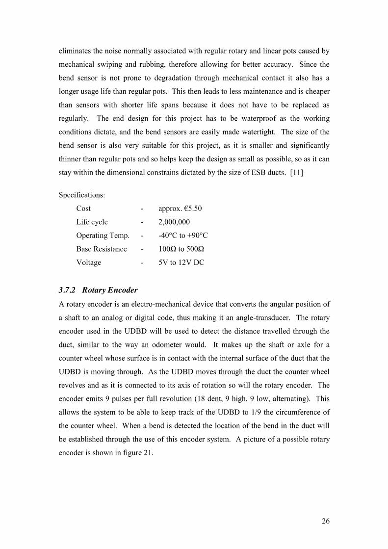
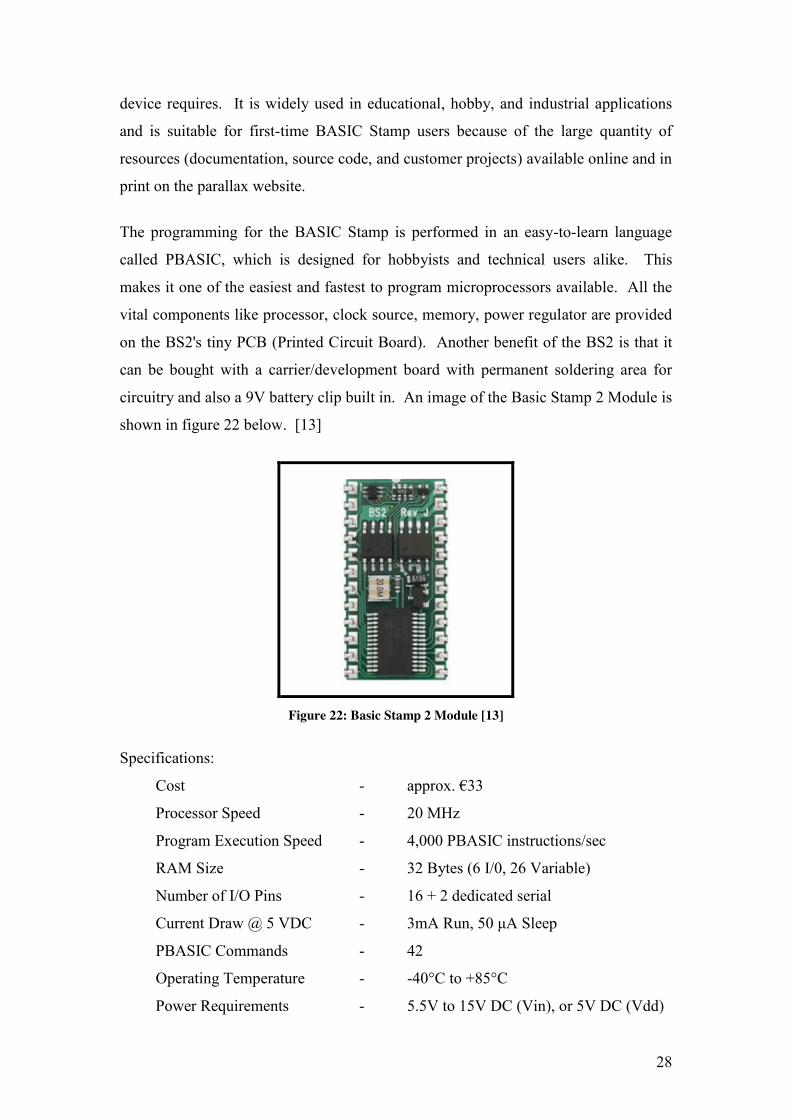
3.7.5 Data-Logger The memory-stick Data-logger, as seen in figure 24 below, is a USB host bridge
which allows information to be transferred through to a USB mass storage device
such as a USB flash drive. This allows the information that the basic stamp records
when the UDBD is in use, to be transferred to a USB key which can then be used to
transfer the files to a PC using simple serial commands. The Data logger is the ideal
device for remote logging of data which is exactly what is needed for this project.
[17]
Figure 24: Data Logger [17]
Specifications:
Cost - €24
Communication - Serial / SPI interface to microcontroller
Power requirements - 5V supply with 3.3V / 5V Safe I/O
Operating temp range - 0°C to +70°C
31
4 METHODOLOGY
The purpose of this section of the report is to explain how the aims and objectives of
this project were met. This includes the methods, procedures, and techniques used to
collect and analyze the information relevant to this project.
Once again the aim of this project is, “To develop the current design concept for
UDBD, both electronically and mechanically, which can then be manufactured, tested
and handed over to ESB Networks”.
This aim will be achieved through the completion of the following objectives.
Objectives 1. Research into any topics/subjects & designs relevant to this project
2. Develop a foundation design based on research carried out
3. Design, Build & Test the Mechanical Device
4. Design, Build & Test the Electronic Circuit
5. Test the completed Device
These objectives are broken down into sub-objectives which must be completed in
order to achieve the main objective.
1. Research into any topics/subjects relevant to this project
(a) Carry out general research for the project using the internet, books and
journals & find out about any existing designs
(b) Arrange an interview with an ESB Networks Cable & Duct Expert & find out
about any important design constraints & requirements
(c) Analyze the previous design based on the information gathered at the meeting
with the ESB Networks cable & duct expert
(d) Find out about any specific standards relevant to the project
(e) Find out about any specific software relevant to the project
2. Develop a foundation design based on research carried out
(a) Critically analyze the previous students design in light of new information
(b) Clarify the objectives & functions for the new design & compare the new
designs characteristics & engineering requirements based on new information
(c) Decide upon the general shape & structure of the new device
32
(d) Construct a flow diagram depicting the electronic components selected for the
device & how they interact
3. Design, Build & Test the Mechanical Device
(a) Investigation into different design possibilities & pre-made parts
(b) Generate 3D Solid Model parts & working drawings so design can be built
(c) Assess Solid Model Parts & redesign where necessary
(d) Build Physical Structure for Device
(e) Assemble & Test Physical Structure in duct to assess functional performance
4 Design, Build & Test the Electronic Circuit
(a) Learn to use the Microprocessor for the development of the Electronic Circuit
(b) Develop the design using sketches & any necessary prototyping equipment
(c) Built & test individual Circuits in relation to the main functions of the Device
(d) Built & test the final circuit now including all the electronics & assess its
performance before integration into the Physical Structure of the Device
6. Test the completed Device
(a) Integrate Electronic Circuit into Physical Structure
(b) Test finished device in duct to assess functional performance
33
5 DEVELOPMENT OF FOUNDATION DESIGN
A basic foundation design for the device must be established before the design of the
physical structure or the electronic circuit can commence. This is of the utmost
importance. The physical structure must facilitate and incorporate the electronic
circuit and the electronic circuit must interact with the dynamics of the physical
structure. It is because of these co-dependencies that a basic foundation design must
be established to allow the design of the physical structure and the design of the
electronic circuit to integrate effectively when each is built and combined in the
finished Device. This proposed foundation design is described in terms of the
Physical Structure and the Electronic Circuit as separate parts of the overall design of
the device.
5.1 Analysis of Investigation into UDBD Requirements
This part of the report analyses all of the information gathered in the first chapter,
which relates to the design of the new UDBD. This is carried out to ensure a clear
idea of what will be required of the Device. This involves the analysis of any design
parameters or constraints, any design objectives that the Device must achieve or
functions it will undergo in operation.
5.1.2 Design Parameters This information gathered at the meeting with the ESB Networks cable and duct
expert had huge implications on the re-design of the previous students UDBD.
1. The design for the previous UDBD could only facilitate the attachment of a
rope at the front end hence leaving the rear of the device with no attachment
point for a rope which would allow the device to be pulled back the way it
came if it became stuck for any reason. The new design would have to
incorporate attachment points at both ends.
2. The speed at which the device travels through the duct is a very important
piece of information as it dictates the momentum that the device would
undergo and hence the tension on the device when it was accelerating. The
34
testing of the previous student’s device was carried out at a speed of 0.75m/s.
However it is now understood that the ESB will be pulling the device through
the ducting at a speed of 3.33 m/s (or 12km/hr). This is considerably faster that
what was designed for in the previous students work. The new design will
have to be able to operate at a speed of 3.33 m/s through the ducting.
3. The inclusion of a mandrel in the group of items which will also be pulled
through the ducting with the UDBD has a big impact on the dimensional
constraints of the new design. The mandrel used is 105mm in diameter and so
the maximum diameter of the device cannot exceed 105mm. If the diameter of
the device exceeds that of the mandrel then the device could fail or become
stuck before the mandrel does. The new design of the device cannot exceed
105mm in diameter, but since it must keep in contact with at least two parallel
points on the inside surface of the duct at any one time to ensure functionality
it will have to have a suspension system which must be able to compress to
allow the device to achieve a diameter no greater than 105mm diameter.
4. Although there is a sponge included in the group of items which will be pulled
through in front of the UDBD which will try and force the majority of water
and grit out of the duct a significant volume of water may still be left behind.
This means that the device must be fully submergible and totally waterproof
so as to protect the electronics housed inside the device. The previous
student’s device was not capable of withstanding full submersion in water.
The new design must be able to withstand full submersion in 2 to 3 feet of
water.
35
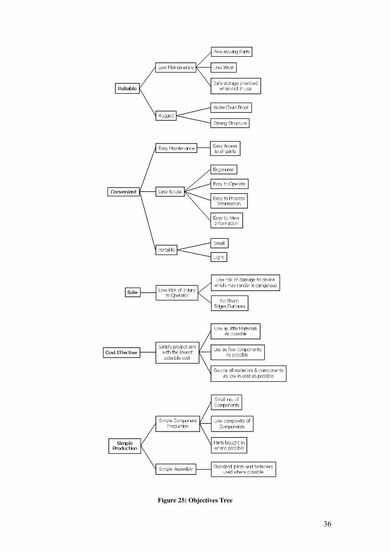
5.1.3 Clarification of Device Objectives Objectives Tree Method (OTM): The OTM was used to establish the way in which the main project objectives will be
satisfied, i.e. develop a means to complete the main objectives through expanding
them into sub-objectives. The main objectives were derived from general
requirements which the designer has deemed necessary for the Device to meet the
Client’s (ESB Networks) needs.
The main objectives were that the UDBD must be Reliable, Convenient, Safe, Cost
Effective and Simple to Produce. These main-objectives were then expanded (from
left to right shown in figure 25) into sub-objectives which would answer the question
of how the main objectives would be achieved. For example one of the main
objectives was that the Device was “Reliable”, as the reliability of the Device was
seen as an important factor. This was then expanded into two sub-objectives which
explained how the Device will achieve this reliability. So, for the Device to be
reliable for the purpose of this project it must be “Rugged” and “Low Maintenance”.
Now these sub-objectives are then expanded into further sub-objectives. For example
“Rugged” is now expanded into two new, more specific, sub-objectives. These new
sub-objectives form the specific means by which the Device will attain its previous
objective, i.e. the Device will be rugged by making it “water / dust proof” and also
giving it a “strong structure”.
36
Figure 25: Objectives Tree
37
5.1.4 Clarification of Device Functions Function Analysis Method (FAM): The FAM was used to establish the necessary functions and sub-functions of the
project’s device and its system boundaries. The FAM diagram is shown in figure 26
on the following page. Human interaction with the device is shown in red writing in
the diagram. The inputs for the displacement of the device in the duct and bends in
the duct’s path are also noted in the diagram in blue writing.
A component or human operator is listed below for each function in the system.
Close down Microprocessor Program - On/Off Switch (Human Operator)
Occurs Outside of Duct
Detach Device - Human Operator
Remove Information - Human Operator
Transport Information to Laptop - Human Operator
Process & View Information - Laptop (running Microsoft Excel)
38
Figure 26: FAM Diagram
39
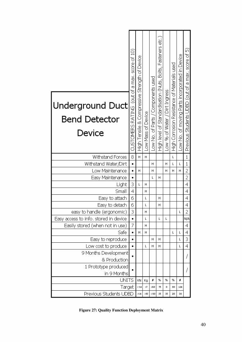
5.1.5 Comparison of Clients’ needs & engineering characteristics Quality Function Deployment (QFD): A QFD Interaction Matrix, as seen in figure 27 on the following page, was
constructed specifically for the UDBD. Interpretation (using software, i.e.
microprocessor programming) of the information gathered by the device was
overlooked during the construction of the matrix.
The customer requirements are listed in the left column under the title of the diagram.
These were derived using OTM and FAM which were completed previously. The
engineering characteristics are listed vertically along the top of the matrix.
The matrix also compares the previous students attempt at developing and producing
an UDBD to this current attempt. This is shown in the column on the far right of the
matrix.
The interactions between the customer’s requirements and the Engineering
characteristics are rated as either H for High or L for Low in regard to how much they
relate or will affect each other. For example the customer requires that the device is
light and so the engineer decides to make it as low in mass as possible. However, this
may interact with or effect other customer requirements and these interactions must be
established so as to achieve as many of the requirements as possible. Hence not all
customer requirements may be able to be met and it is the recognition of these clashes
and selection of what requirements can be met that is important.
The customer requirements were suggested by the student and prioritized by the client
himself. The client is a member of staff in the ESB Networks (ESB Cable and Duct
Expert) working with the student carrying out the final year project that this
assignment is based on. A meeting was arranged with the client and these
requirements were discussed in depth. A questionnaire was then completed by the
client and that was how the customer rating of the requirements was attained for the
QFD Interaction Matrix in figure 27. The questionnaire used to attain the customer’s
rating of requirements is shown in Chapter 3 in the report.
40
Figure 27: Quality Function Deployment Matrix
41
5.2 Foundation Design for Physical Structure
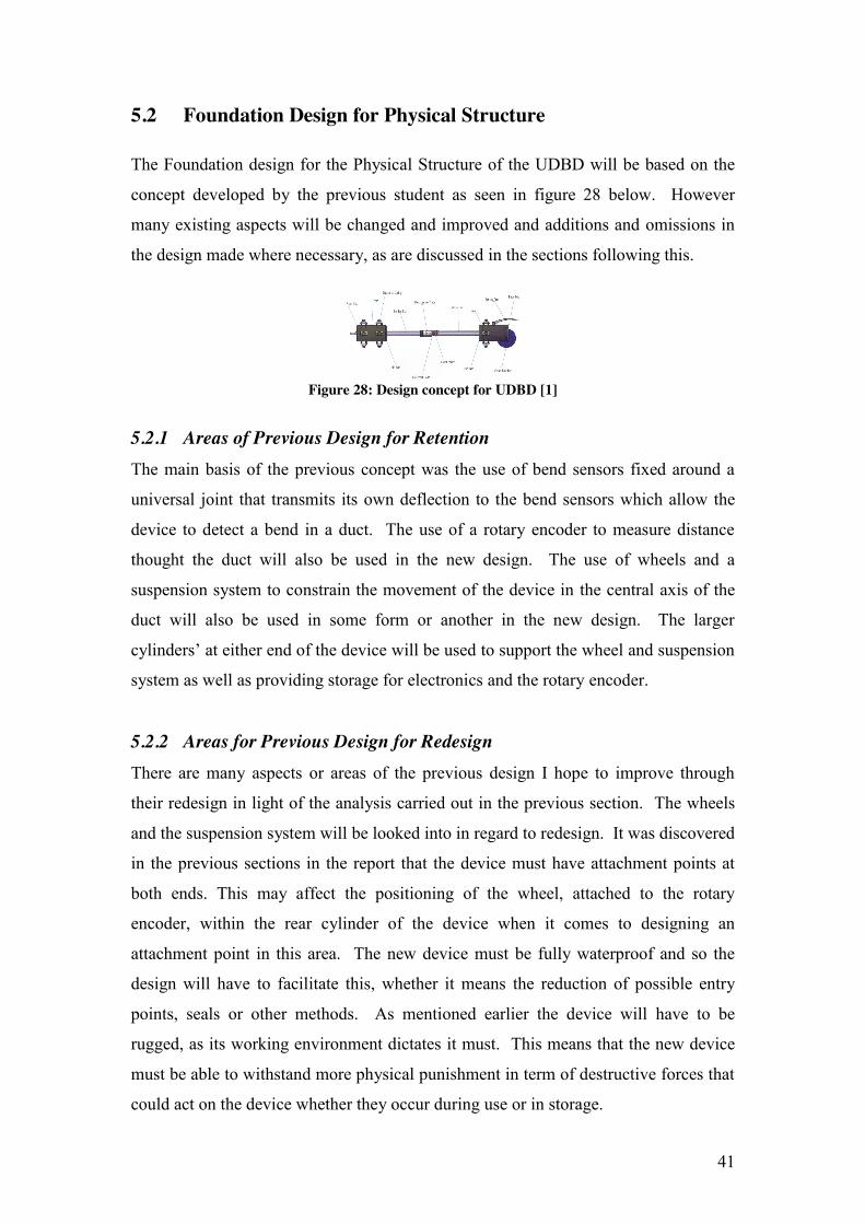
The Foundation design for the Physical Structure of the UDBD will be based on the
concept developed by the previous student as seen in figure 28 below. However
many existing aspects will be changed and improved and additions and omissions in
the design made where necessary, as are discussed in the sections following this.
Figure 28: Design concept for UDBD [1]
5.2.1 Areas of Previous Design for Retention
The main basis of the previous concept was the use of bend sensors fixed around a
universal joint that transmits its own deflection to the bend sensors which allow the
device to detect a bend in a duct. The use of a rotary encoder to measure distance
thought the duct will also be used in the new design. The use of wheels and a
suspension system to constrain the movement of the device in the central axis of the
duct will also be used in some form or another in the new design. The larger
cylinders’ at either end of the device will be used to support the wheel and suspension
system as well as providing storage for electronics and the rotary encoder.
5.2.2 Areas for Previous Design for Redesign There are many aspects or areas of the previous design I hope to improve through
their redesign in light of the analysis carried out in the previous section. The wheels
and the suspension system will be looked into in regard to redesign. It was discovered
in the previous sections in the report that the device must have attachment points at
both ends. This may affect the positioning of the wheel, attached to the rotary
encoder, within the rear cylinder of the device when it comes to designing an
attachment point in this area. The new device must be fully waterproof and so the
design will have to facilitate this, whether it means the reduction of possible entry
points, seals or other methods. As mentioned earlier the device will have to be
rugged, as its working environment dictates it must. This means that the new device
must be able to withstand more physical punishment in term of destructive forces that
could act on the device whether they occur during use or in storage.
42
5.3 Foundation Design for Electronic Circuit
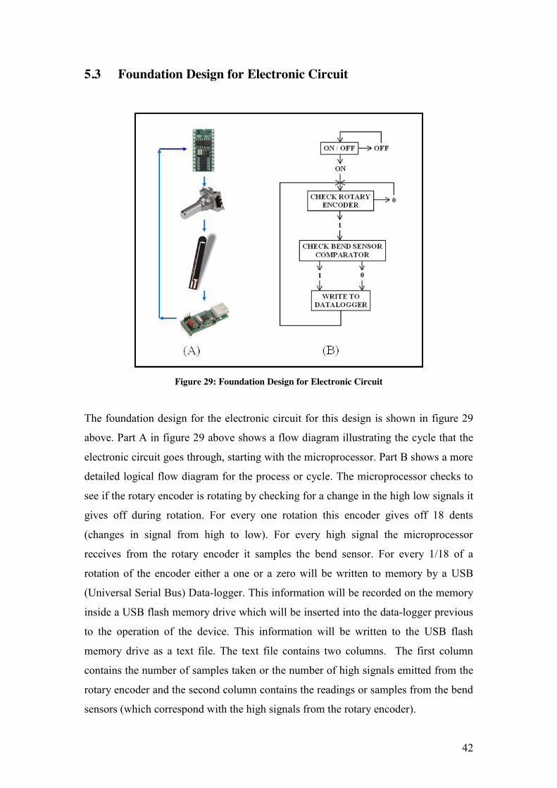
Figure 29: Foundation Design for Electronic Circuit
The foundation design for the electronic circuit for this design is shown in figure 29
above. Part A in figure 29 above shows a flow diagram illustrating the cycle that the
electronic circuit goes through, starting with the microprocessor. Part B shows a more
detailed logical flow diagram for the process or cycle. The microprocessor checks to
see if the rotary encoder is rotating by checking for a change in the high low signals it
gives off during rotation. For every one rotation this encoder gives off 18 dents
(changes in signal from high to low). For every high signal the microprocessor
receives from the rotary encoder it samples the bend sensor. For every 1/18 of a
rotation of the encoder either a one or a zero will be written to memory by a USB
(Universal Serial Bus) Data-logger. This information will be recorded on the memory
inside a USB flash memory drive which will be inserted into the data-logger previous
to the operation of the device. This information will be written to the USB flash
memory drive as a text file. The text file contains two columns. The first column
contains the number of samples taken or the number of high signals emitted from the
rotary encoder and the second column contains the readings or samples from the bend
sensors (which correspond with the high signals from the rotary encoder).
43
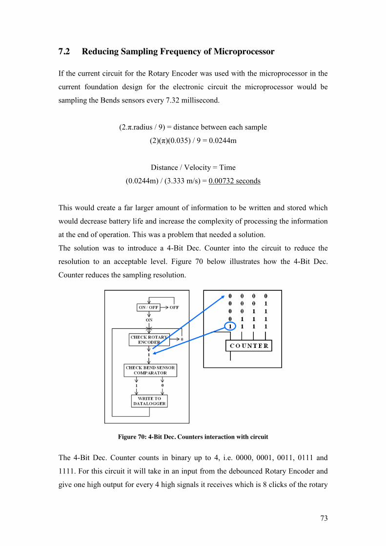
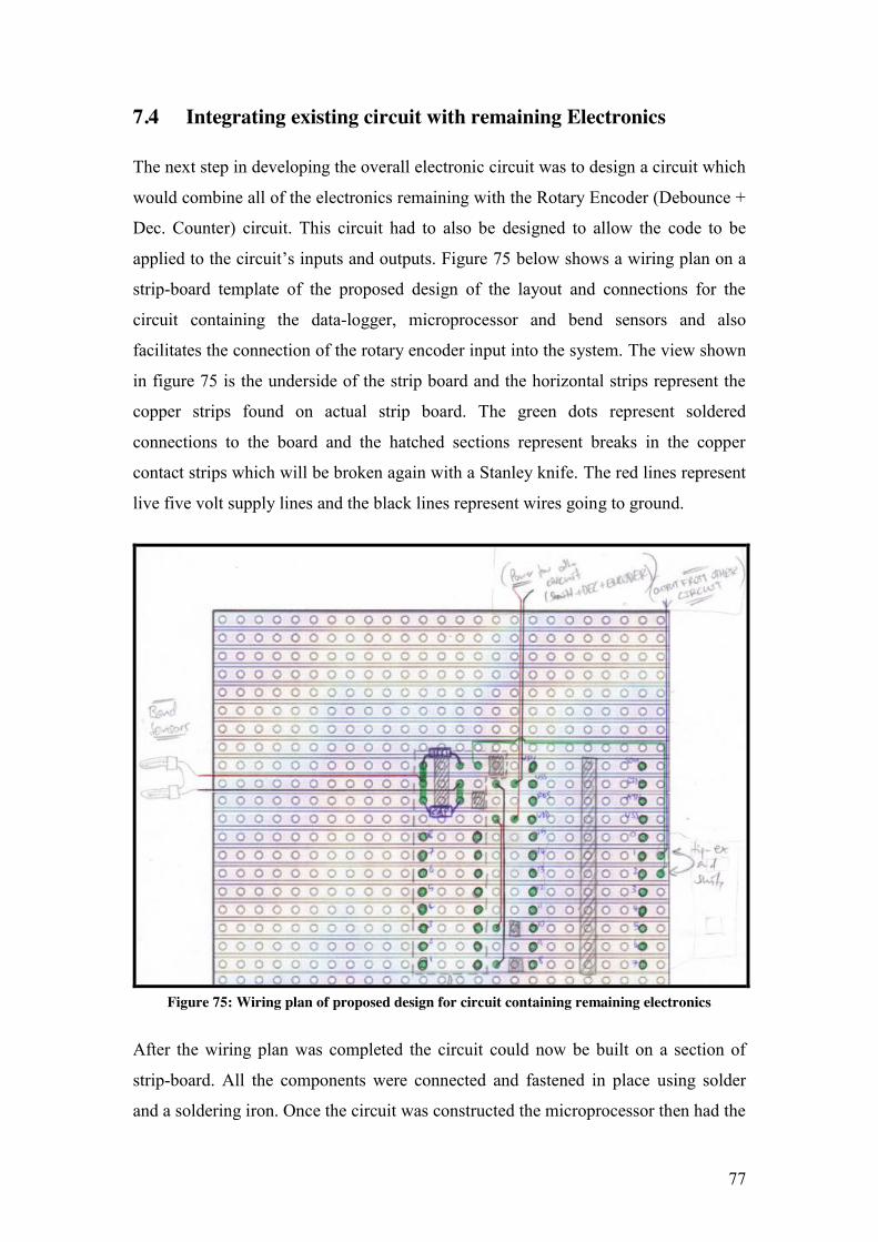
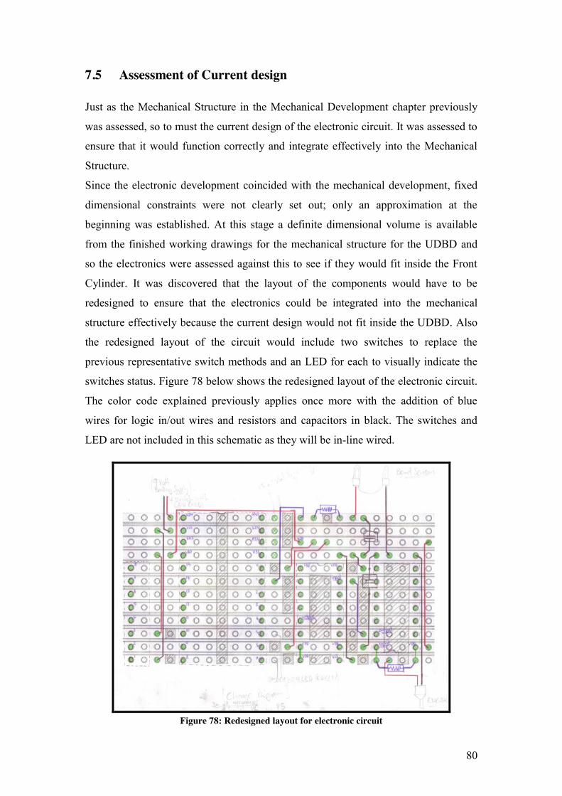
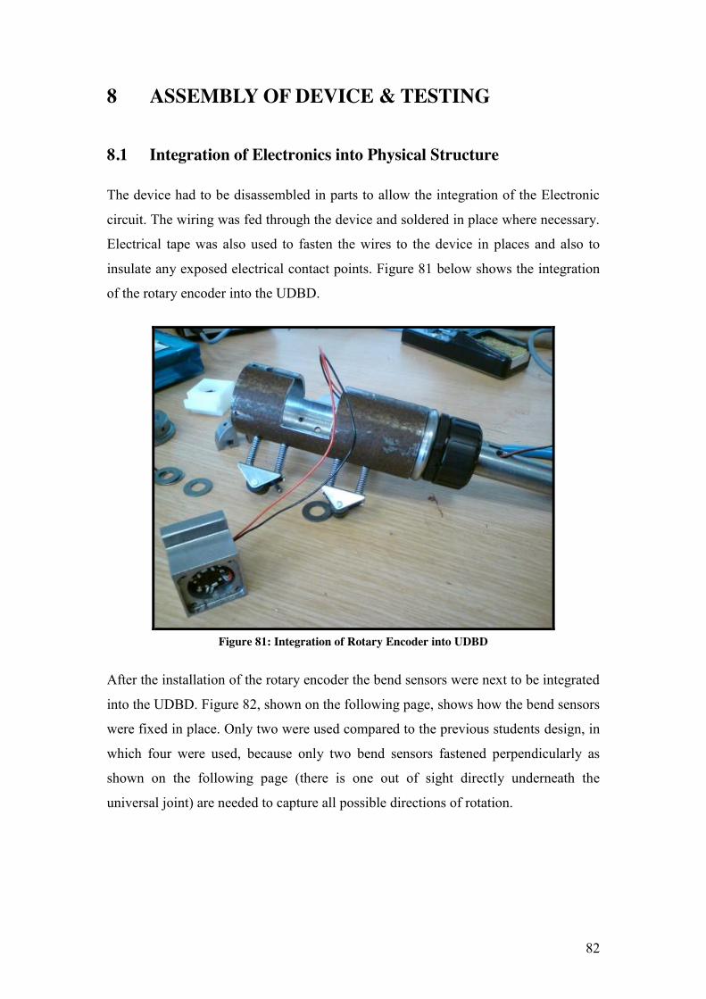
6 MECHANICAL DEVELOPMENT
This section looks into the mechanical development of the UDBD. It goes through
the design, manufacturing and testing of this aspect of the device in detail.
6.1 Investigation into Different Design Possibilities
The requirements and specifications for the design have been established in the
previous sections of the report. Now the job is to start to develop a design which can
physically satisfy these requirements and meet the prescribed specifications. Samples
of the sketches made during the development of the design are shown following this.
Not all the sketches have been included but enough examples are there to show the
different ideas and concepts which were investigated. The focus on the design was
split into four main sections to allow the designer to concentrate on each aspect
individually to ensure that no part of the design was overlooked.
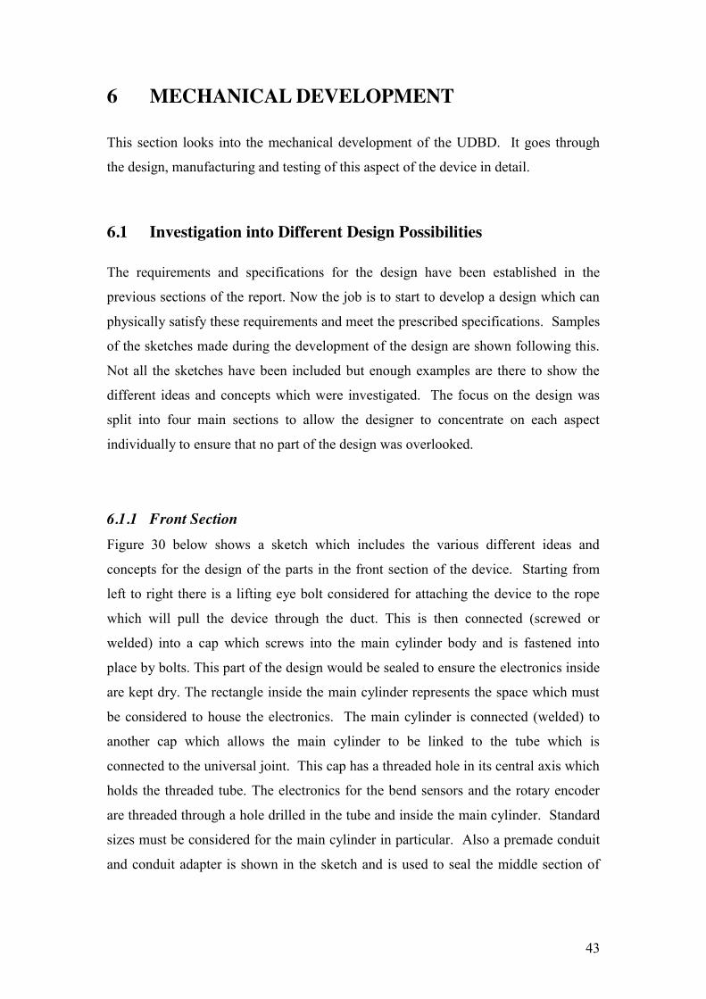
6.1.1 Front Section Figure 30 below shows a sketch which includes the various different ideas and
concepts for the design of the parts in the front section of the device. Starting from
left to right there is a lifting eye bolt considered for attaching the device to the rope
which will pull the device through the duct. This is then connected (screwed or
welded) into a cap which screws into the main cylinder body and is fastened into
place by bolts. This part of the design would be sealed to ensure the electronics inside
are kept dry. The rectangle inside the main cylinder represents the space which must
be considered to house the electronics. The main cylinder is connected (welded) to
another cap which allows the main cylinder to be linked to the tube which is
connected to the universal joint. This cap has a threaded hole in its central axis which
holds the threaded tube. The electronics for the bend sensors and the rotary encoder
are threaded through a hole drilled in the tube and inside the main cylinder. Standard
sizes must be considered for the main cylinder in particular. Also a premade conduit
and conduit adapter is shown in the sketch and is used to seal the middle section of
44
the device and also provide protection for the bend sensors and electronics on the
middle section.
Figure 30: Front Section Design Sketch
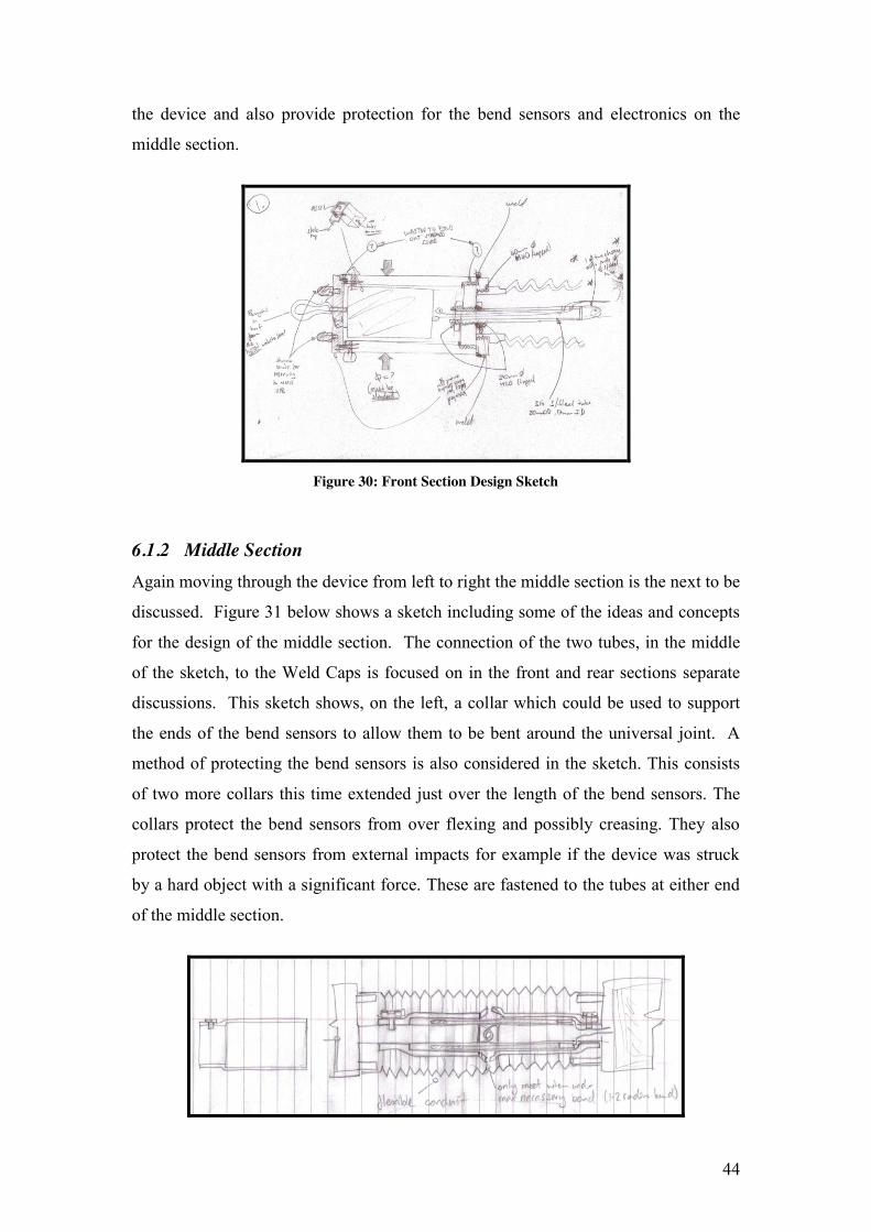
6.1.2 Middle Section Again moving through the device from left to right the middle section is the next to be
discussed. Figure 31 below shows a sketch including some of the ideas and concepts
for the design of the middle section. The connection of the two tubes, in the middle
of the sketch, to the Weld Caps is focused on in the front and rear sections separate
discussions. This sketch shows, on the left, a collar which could be used to support
the ends of the bend sensors to allow them to be bent around the universal joint. A
method of protecting the bend sensors is also considered in the sketch. This consists
of two more collars this time extended just over the length of the bend sensors. The
collars protect the bend sensors from over flexing and possibly creasing. They also
protect the bend sensors from external impacts for example if the device was struck
by a hard object with a significant force. These are fastened to the tubes at either end
of the middle section.
45
Figure 31: Middle Section Design Sketch
6.1.3 Rear Section The design of the rear section of the device was one of the most challenging parts of
the mechanical development of the UDBD. The previous students design only had
the facilities for one end to be attached. However after gathering more information on
the requirements of the design it was discovered (as discussed previously in the
report) that the design must be able to be pulled back through the duct if the device
encounters an obstacle that it cannot pass, hence it must have attachment points at
both of its ends.
Many different options were investigated and it was concluded that the odometer
wheel (large wheel connected to rotary encoder) would have to be moved in towards
the middle of the rear cylinder as opposed to the end where it was situated on the
previous design. This meant an entire redesign of the odometer wheel and encoder
support system. The challenge was to ensure an odometer wheel diameter large
enough to reach the inside surface of the duct and also to keep the encoder as close to
the center of the duct as possible, so as to reduce possible interference with the duct
surface when encountering bends. At the same time however, the wheel also had to
be small enough to ensure that it would still allow enough clearance on the far side for
the suspension system to reduce the diameter of the overall device to a minimum of
105mm (the mandrel diameter). As well as these dimensional constraints the design
also had to take into account the ability of the encoder housing to be sealed from
water intrusion. Figure 32 below shows a side section and end section sketched view
of the first design for the rear section of the device. The connection to the middle
section and attachment point part of the design was somewhat neglected as it was
dealt with in the design for the front section.
46
Figure 32: Rear Section Design Sketch
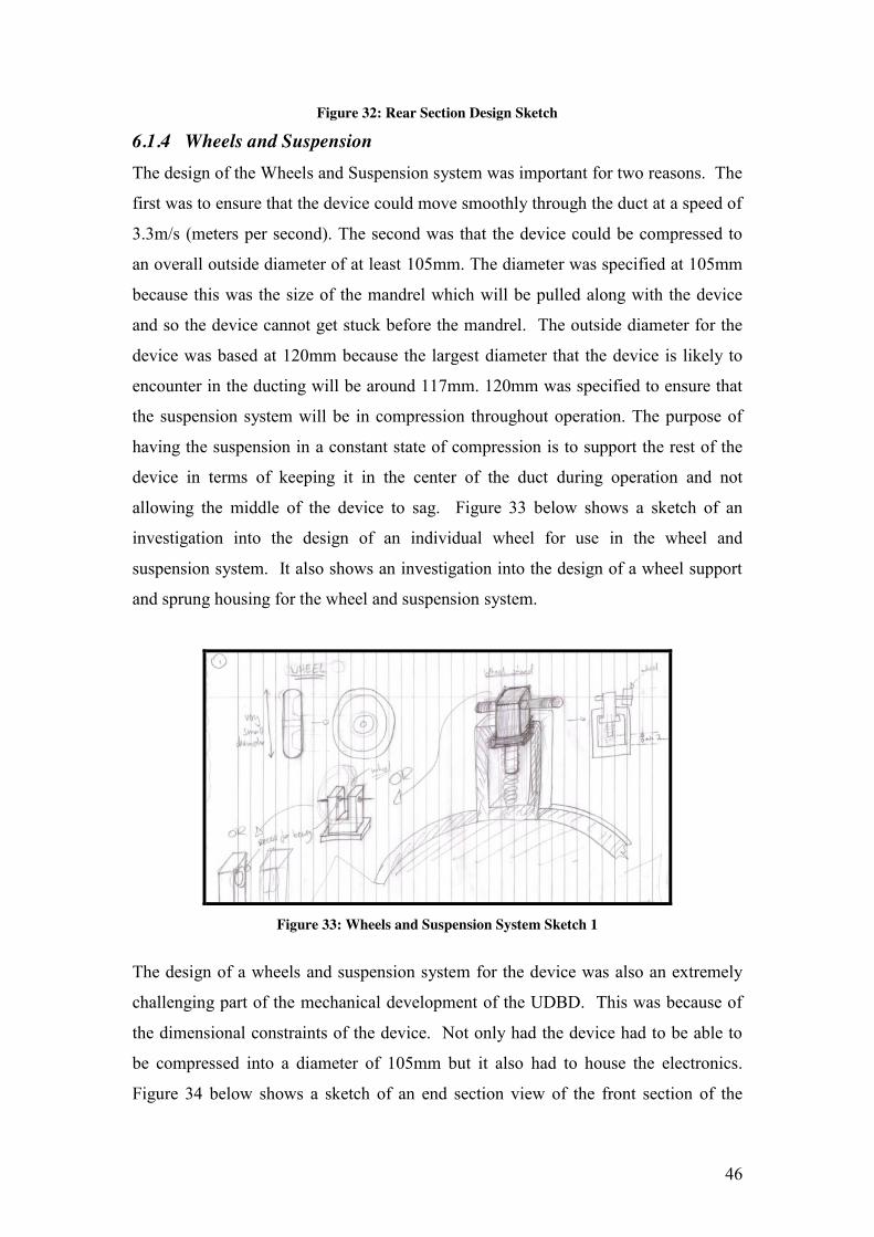
6.1.4 Wheels and Suspension The design of the Wheels and Suspension system was important for two reasons. The
first was to ensure that the device could move smoothly through the duct at a speed of
3.3m/s (meters per second). The second was that the device could be compressed to
an overall outside diameter of at least 105mm. The diameter was specified at 105mm
because this was the size of the mandrel which will be pulled along with the device
and so the device cannot get stuck before the mandrel. The outside diameter for the
device was based at 120mm because the largest diameter that the device is likely to
encounter in the ducting will be around 117mm. 120mm was specified to ensure that
the suspension system will be in compression throughout operation. The purpose of
having the suspension in a constant state of compression is to support the rest of the
device in terms of keeping it in the center of the duct during operation and not
allowing the middle of the device to sag. Figure 33 below shows a sketch of an
investigation into the design of an individual wheel for use in the wheel and
suspension system. It also shows an investigation into the design of a wheel support
and sprung housing for the wheel and suspension system.
Figure 33: Wheels and Suspension System Sketch 1
The design of a wheels and suspension system for the device was also an extremely
challenging part of the mechanical development of the UDBD. This was because of
the dimensional constraints of the device. Not only had the device had to be able to
be compressed into a diameter of 105mm but it also had to house the electronics.
Figure 34 below shows a sketch of an end section view of the front section of the
47
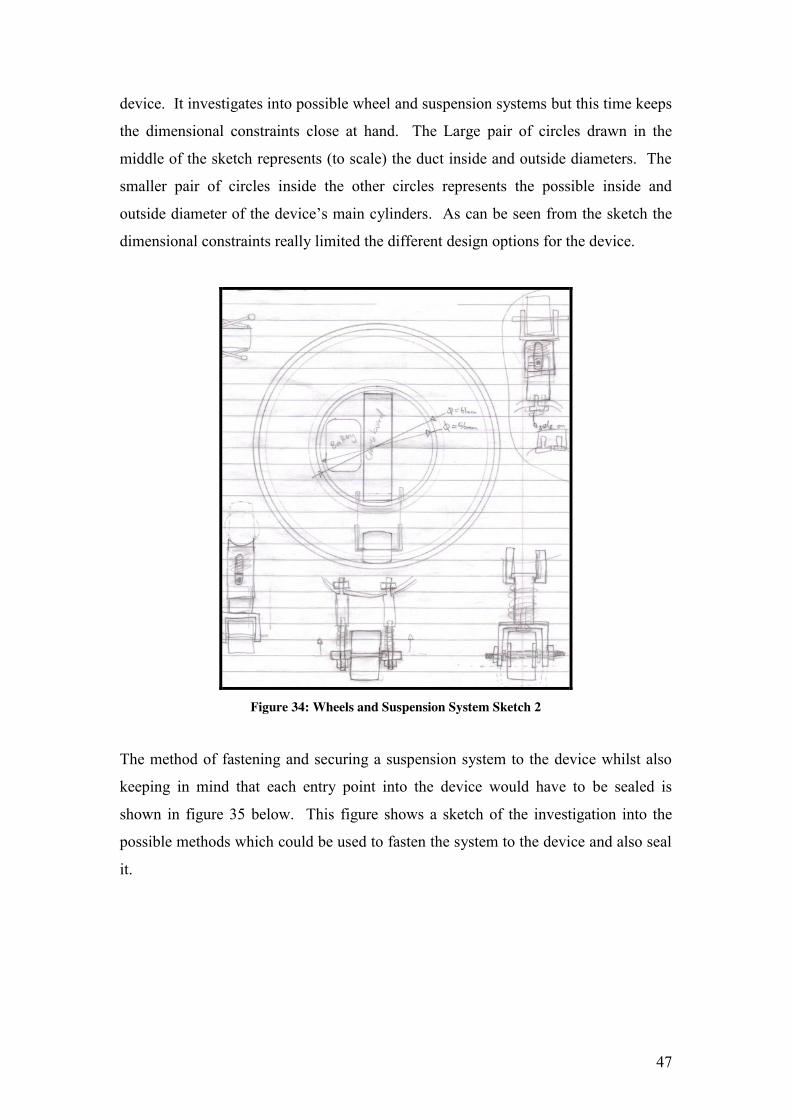
device. It investigates into possible wheel and suspension systems but this time keeps
the dimensional constraints close at hand. The Large pair of circles drawn in the
middle of the sketch represents (to scale) the duct inside and outside diameters. The
smaller pair of circles inside the other circles represents the possible inside and
outside diameter of the device’s main cylinders. As can be seen from the sketch the
dimensional constraints really limited the different design options for the device.
Figure 34: Wheels and Suspension System Sketch 2
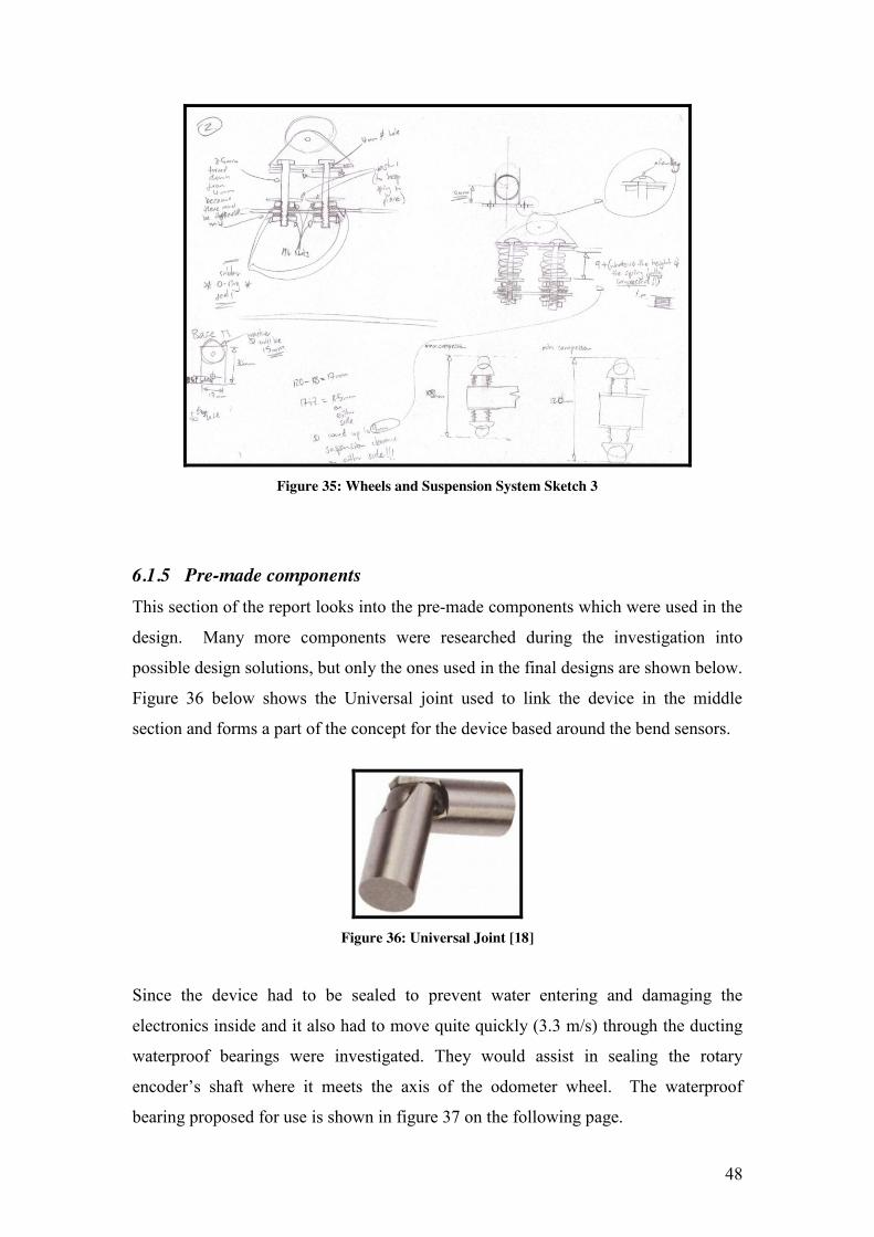
The method of fastening and securing a suspension system to the device whilst also
keeping in mind that each entry point into the device would have to be sealed is
shown in figure 35 below. This figure shows a sketch of the investigation into the
possible methods which could be used to fasten the system to the device and also seal
it.
48
Figure 35: Wheels and Suspension System Sketch 3
6.1.5 Pre-made components This section of the report looks into the pre-made components which were used in the
design. Many more components were researched during the investigation into
possible design solutions, but only the ones used in the final designs are shown below.
Figure 36 below shows the Universal joint used to link the device in the middle
section and forms a part of the concept for the device based around the bend sensors.
Figure 36: Universal Joint [18]
Since the device had to be sealed to prevent water entering and damaging the
electronics inside and it also had to move quite quickly (3.3 m/s) through the ducting
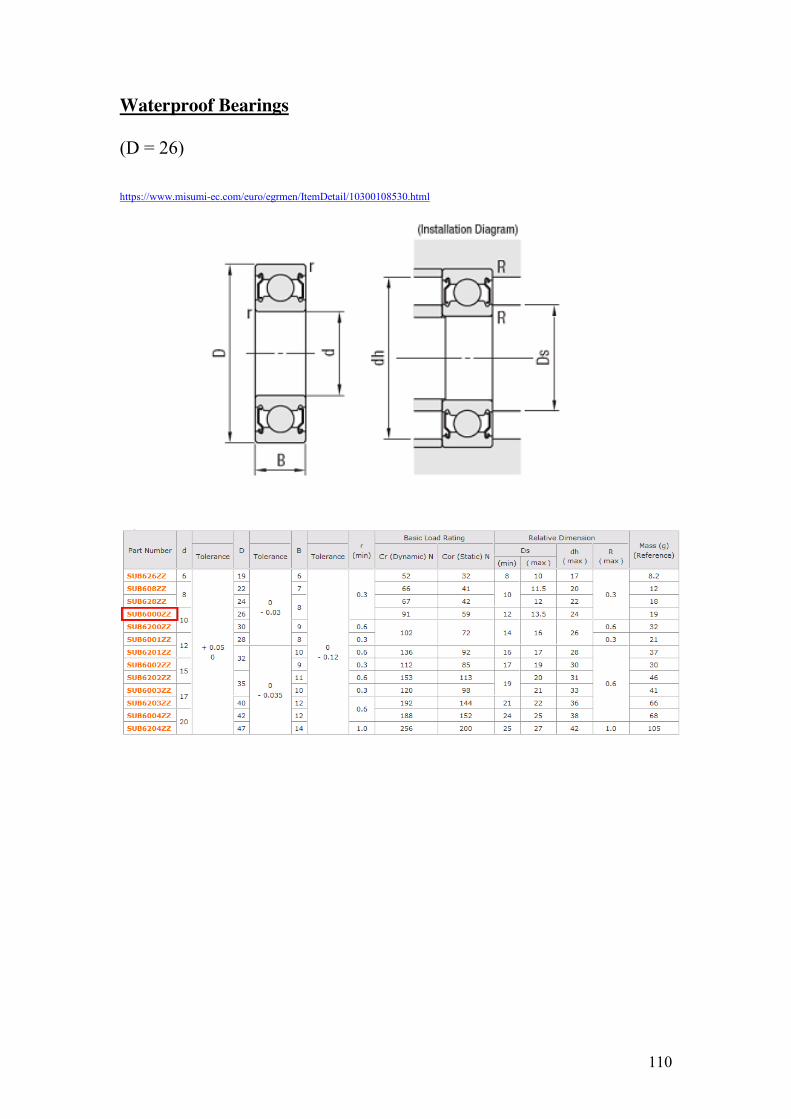
waterproof bearings were investigated. They would assist in sealing the rotary
encoder’s shaft where it meets the axis of the odometer wheel. The waterproof
bearing proposed for use is shown in figure 37 on the following page.
49
Figure 37: Waterproof Bearing [19]
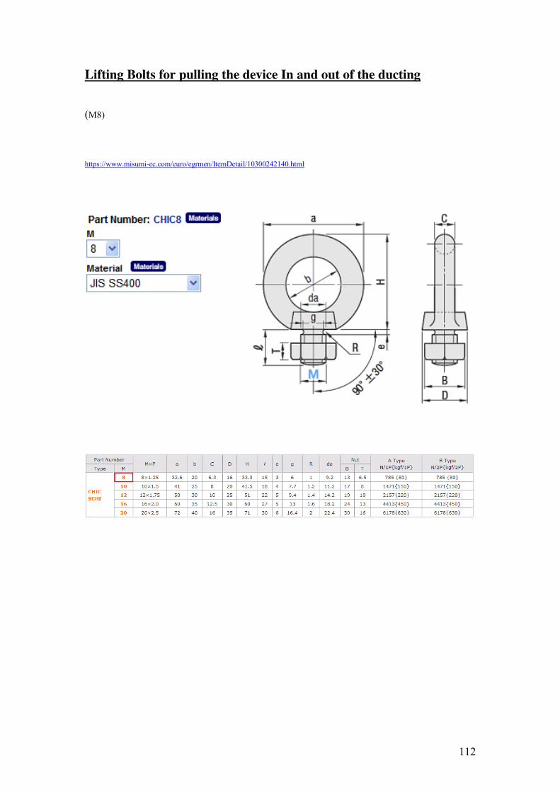
At either end of the device there will be an attachment point allowing the device to be
connected to a rope for operation in the ducting. As mentioned previously these
attachment points will be made up of a lifting eye bolt as shown in figure 38 below.
Figure 38: Lifting Eye Bolt [20]
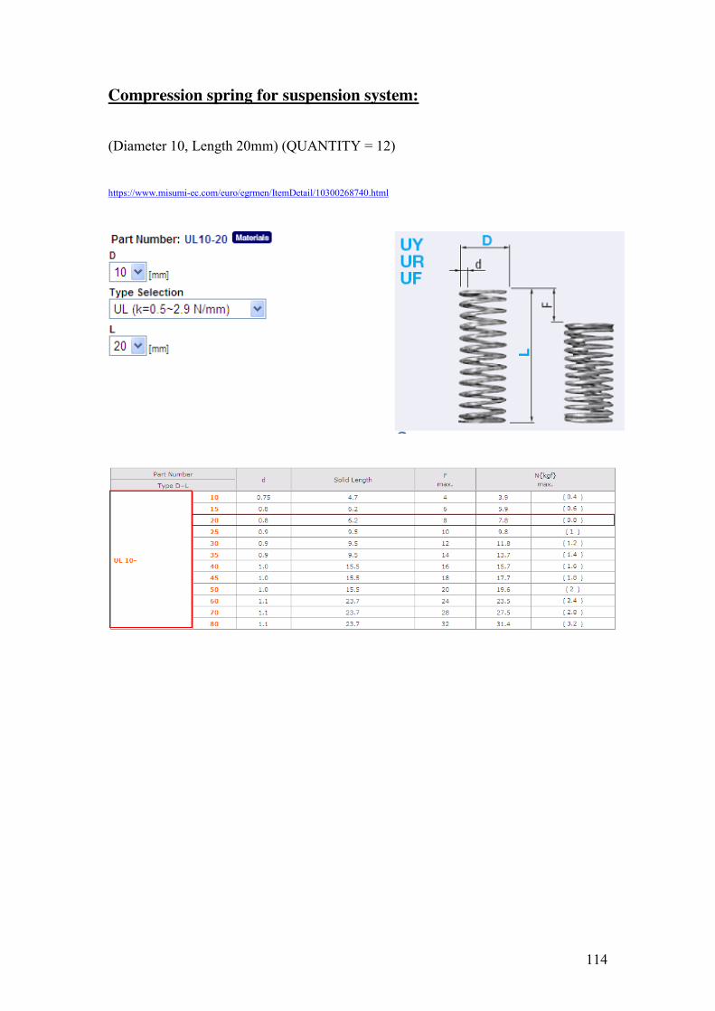
Integrated into the wheel and suspension system will be compression springs. These
will use kinetic energy to generate a force to ensure that the device will move inline
with the central axis of the ducting when they are compressed. The stainless steel
compression spring suggested for this is shown in figure 39 below.
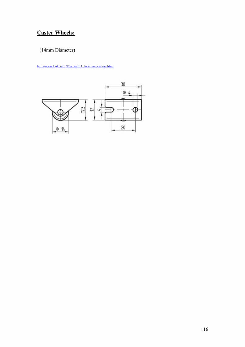
Figure 39: Compression Spring [21]
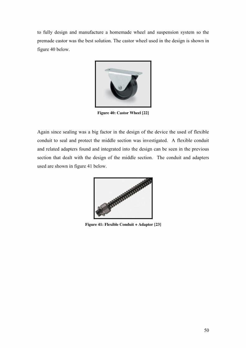
After investigation into the different solutions to the Wheels and Suspension section
of the design it was decided that the castor wheels used in the previous students
design would be the best for the task. It would be too time-consuming and expensive
50
to fully design and manufacture a homemade wheel and suspension system so the
premade castor was the best solution. The castor wheel used in the design is shown in
figure 40 below.
Figure 40: Castor Wheel [22]
Again since sealing was a big factor in the design of the device the used of flexible
conduit to seal and protect the middle section was investigated. A flexible conduit
and related adapters found and integrated into the design can be seen in the previous
section that dealt with the design of the middle section. The conduit and adapters
used are shown in figure 41 below.
Figure 41: Flexible Conduit + Adapter [23]
51
6.2 Selection of Design Options & Generation of 3D Solid Models
The next step, after the investigation into the different possible design solutions, was
to decide on the best options to take regarding the design and generate 3D models of
the parts which needed to be manufactured for the device. The generation of the
proposed design in a CAD package also helped to visualize the design and allowed a
better assessment of the design afterwards. Solid Edge was used to generate the solid
models for the parts for manufacture. Once the solid models were generated working
dimensioned drawings for each part and any other required drawings were produced.
For the sake of clarity the design will be explained starting from the front and ending
at the rear.
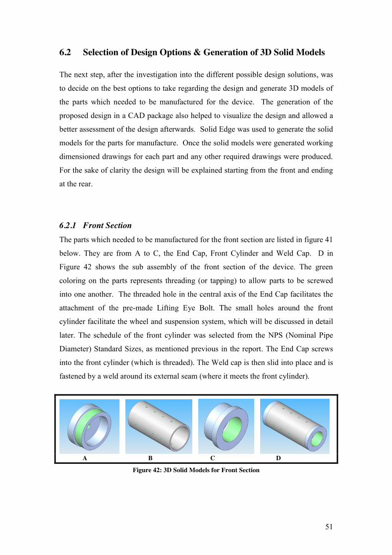
6.2.1 Front Section The parts which needed to be manufactured for the front section are listed in figure 41
below. They are from A to C, the End Cap, Front Cylinder and Weld Cap. D in
Figure 42 shows the sub assembly of the front section of the device. The green
coloring on the parts represents threading (or tapping) to allow parts to be screwed
into one another. The threaded hole in the central axis of the End Cap facilitates the
attachment of the pre-made Lifting Eye Bolt. The small holes around the front
cylinder facilitate the wheel and suspension system, which will be discussed in detail
later. The schedule of the front cylinder was selected from the NPS (Nominal Pipe
Diameter) Standard Sizes, as mentioned previous in the report. The End Cap screws
into the front cylinder (which is threaded). The Weld cap is then slid into place and is
fastened by a weld around its external seam (where it meets the front cylinder).
A B C D
Figure 42: 3D Solid Models for Front Section
52
6.2.2 Middle Section The only specific parts which need to be manufactured for the middle section are the
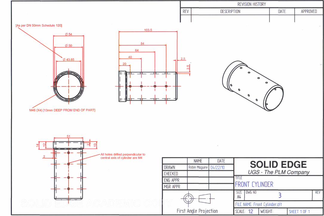
Front and Rear Tubes. These are shown respectively in Figure 43. A in figure 43
shows the tubes themselves whilst B shows a sub assembly of the tubes and the Weld
Caps, to which each of them will be welded. The weld will be laid on the end of the
tubes where their end surface is flush with the Weld Cap’s outside surface. There are
also holes to facilitate a fastener (type of screw) to hold the universal joint in place
between the two tubes.
A B
Figure 43: 3D Solid Models for Middle Section
6.2.3 Rear Section In this design the Weld Cap and End Cap, as discussed previously, are used in the
same manner as they were used in the Front Section. It was proposed that two of each
of the components would be produced. The main function of the Rear Section of the
device was to house the distance measurement system and all that it encapsulates.
Figure 44, shown on the following page, shows the selection of components which
make up a part of this system. It must be noted that parts A and C are premade parts
and were only generated as Solid Models for illustration purposes. The parts, from A
to E are as follows, the Rotary Encoder, Shaft (Key is separate part but is shown
inserted into B), Waterproof Bearings, Spacers and Wheel. The Rotary Encoder Slots
into the Shaft and is fastened in place with a set screw (of standard size). This
assembly is then slotted into the first Bearing and then slotted into the first spacer.
The assembly is then lined up with wheel (for the keyway) and it is slotted into the
53
wheel. Following this the remaining spacer and Bearing are slid on in that order. F in
Figure 44 shows this completed sub assembly.
A B C D E F
Figure 44: 3D Solid Models for Rear Section
The sub assembly in part F in Figure 44 is housed in the Rear Wheel Support which is
shown in figure 45 below. This was one of the more detailed and complex parts
which had to be designed and manufactured for the device. Figure 45 shows two
views of the Rear Wheel Support. This part is basically a 3D Solid Model of the part
sketched in Figure 32, shown previously in the report. The holes, visible in the top of
the part (in the view shown in A), allow the part to be fastened into the Rear Cylinder.
The parts in the Rear section would be assembled as follows. One of the Bearings
would be slotted into the back of the part and once the wheel and spacer are aligned
the rest of the assembly could be slotted in through the hollow square section which
housed the Rotary Encoder. This hollow section then has a plate (not shown) inserted
into the recessed rectangular space and this is fastened in place and sealed with some
kind of metal sealing solution to ensure the rotary encoder is protected from water
intrusion.
A B
Figure 45: 3D Solid Models for Wheels Support in Rear Section
54
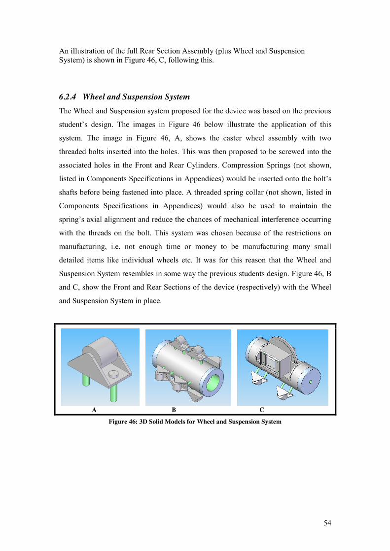
An illustration of the full Rear Section Assembly (plus Wheel and Suspension System) is shown in Figure 46, C, following this.
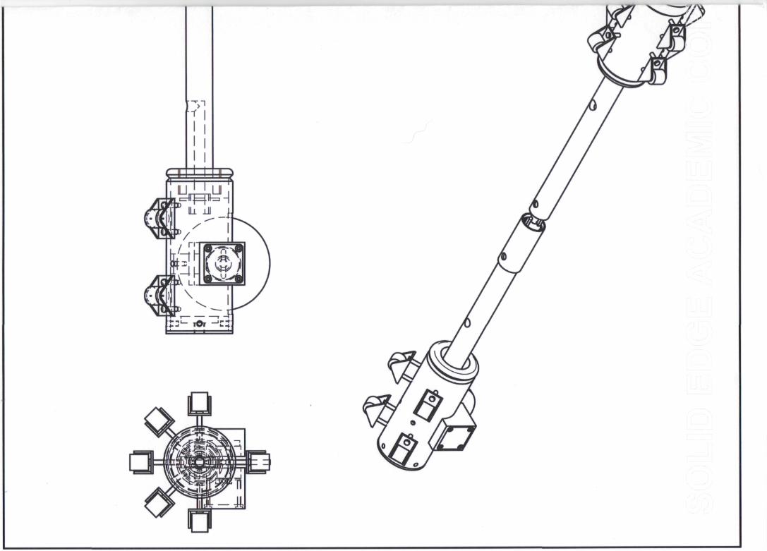
6.2.4 Wheel and Suspension System The Wheel and Suspension system proposed for the device was based on the previous
student’s design. The images in Figure 46 below illustrate the application of this
system. The image in Figure 46, A, shows the caster wheel assembly with two
threaded bolts inserted into the holes. This was then proposed to be screwed into the
associated holes in the Front and Rear Cylinders. Compression Springs (not shown,
listed in Components Specifications in Appendices) would be inserted onto the bolt’s
shafts before being fastened into place. A threaded spring collar (not shown, listed in
Components Specifications in Appendices) would also be used to maintain the
spring’s axial alignment and reduce the chances of mechanical interference occurring
with the threads on the bolt. This system was chosen because of the restrictions on
manufacturing, i.e. not enough time or money to be manufacturing many small
detailed items like individual wheels etc. It was for this reason that the Wheel and
Suspension System resembles in some way the previous students design. Figure 46, B
and C, show the Front and Rear Sections of the device (respectively) with the Wheel
and Suspension System in place.
A B C
Figure 46: 3D Solid Models for Wheel and Suspension System
55
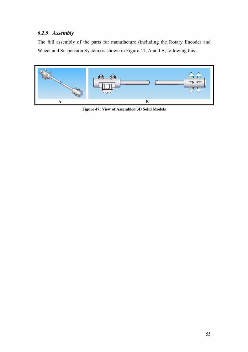
6.2.5 Assembly The full assembly of the parts for manufacture (including the Rotary Encoder and
Wheel and Suspension System) is shown in Figure 47, A and B, following this.
A B
Figure 47: View of Assembled 3D Solid Models
56
6.3 Assessment and Redesign
This part of the report deals with the assessment of the current design and the
necessary alterations or redesign required. The basis for the assessment of the design
was based on four main factors.
6.3.1 Basis of Assessment 1 Ability to satisfy overall design requirements
The first factor taken into account, when assessing the current design, was the ability
of the parts to individually and collectively satisfy the relevant requirements of the
device. For instance the front section of the device had to be fully sealed to prevent
any water ingress; hence each of the parts that make up this section must each
contribute to satisfy this requirement. If they do not, their designs must be altered in
some way to ensure that they do. This included the requirements brought about by the
integration and interaction of the electronics with the mechanical design of the device. 2 Time required to Manufacture
The second factor taken into account, when assessing the current design, was the time
it would actually take to manufacture the parts discussed previously. This took into
account the overall time to machine the parts themselves. It also took into account the
availability of materials, i.e. a rare or less commonly used material would be less
likely to be in stock when required, hence the selection of a more commonly used
material would save time in this regard. It was for this reason that mild steel was
selected for the manufacturing of all of the parts. Stainless Steel (316 to be specific)
would have been preferred due to its corrosion resistant properties and ease of
cleaning but the delay would have been too great and there wouldn’t have been a
physical device for testing before the project deadline. Mild Steel was the easiest to
attain in the time allowed and the closest commonly used material to the properties of
Stainless Steel.
3 Cost required to Manufacture
The third factor taken into account, when assessing the current design, was the cost
which would be incurred through the manufacture of the parts. This also took into
account the time taken to manufacture the parts, as the labour required would be
57
charged by the hour. The simpler and less complex the design the less time it would
take to machine. The cost of the materials used would also contribute to the overall
cost to manufacture the parts. This coincides with the previous decision to select Mild
Steel as the material for the parts for manufacture as Mild Steel is significantly
cheaper than Stainless Steel. 4 Assembly of the Device
The fourth factor taken into account, when assessing the design, was the actual
assembly of the device after manufacture, i.e. reviewing the functionality of the
device in terms of its ability to be assembled after it has been manufactured. This
included the assembly of the mechanical parts and components (with fasteners etc.)
and also included the integration of the electronics and wiring in the device. This
factor was very important because if it were overlooked it would increase the chances
of the device not being able to be assembled, which would be a waste of time and
money.
6.3.2 Redesign The assessment led to some alterations in the design and also the complete redesign of
certain parts. Some of the changes were made to simplify the device and others to
help it better fulfil its tasks. These changes to the design are listed below.
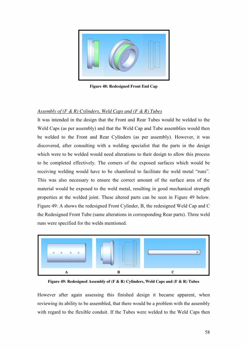
Front End Cap
When this part was assessed it was decided that it did not provide a satisfactory seal
with the front cylinder when fastened in place. It also was seen to have unsafe sharp
edges which were also lending no benefit to the device only adding extra material
which adds to the weight of the device and also could pose a danger to users. The
redesigned part is shown in various views in Figure 48 below. It can also be seen in
the figure that a gap, between where the threads meet the surface on this part and
where that meets the end of the front cylinder face, has been incorporated into the
design. This gap facilitates the insertion of an O-Ring (specified to standard size,
check appendices) to increase the sealing properties of this area of the device.
58
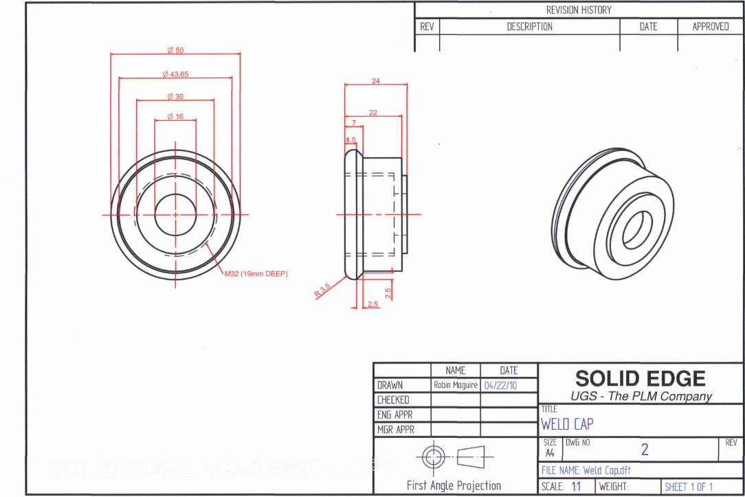
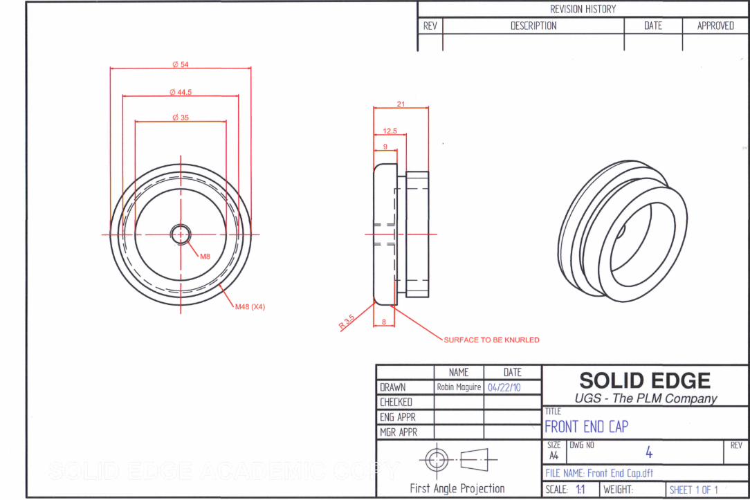
Figure 48: Redesigned Front End Cap
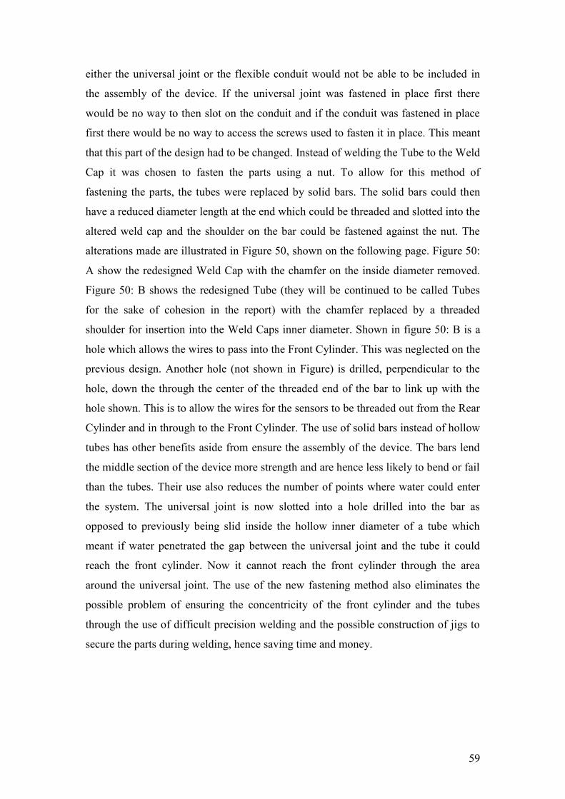
Assembly of (F & R) Cylinders, Weld Caps and (F & R) Tubes
It was intended in the design that the Front and Rear Tubes would be welded to the
Weld Caps (as per assembly) and that the Weld Cap and Tube assemblies would then
be welded to the Front and Rear Cylinders (as per assembly). However, it was
discovered, after consulting with a welding specialist that the parts in the design
which were to be welded would need alterations to their design to allow this process
to be completed effectively. The corners of the exposed surfaces which would be
receiving welding would have to be chamfered to facilitate the weld metal “runs”.
This was also necessary to ensure the correct amount of the surface area of the
material would be exposed to the weld metal, resulting in good mechanical strength
properties at the welded joint. These altered parts can be seen in Figure 49 below.
Figure 49: A shows the redesigned Front Cylinder, B, the redesigned Weld Cap and C
the Redesigned Front Tube (same alterations in corresponding Rear parts). Three weld
runs were specified for the welds mentioned.
Figure 49: Redesigned Assembly of (F & R) Cylinders, Weld Caps and (F & R) Tubes
However after again assessing this finished design it became apparent, when
reviewing its ability to be assembled, that there would be a problem with the assembly
with regard to the flexible conduit. If the Tubes were welded to the Weld Caps then
59
either the universal joint or the flexible conduit would not be able to be included in
the assembly of the device. If the universal joint was fastened in place first there
would be no way to then slot on the conduit and if the conduit was fastened in place
first there would be no way to access the screws used to fasten it in place. This meant
that this part of the design had to be changed. Instead of welding the Tube to the Weld
Cap it was chosen to fasten the parts using a nut. To allow for this method of
fastening the parts, the tubes were replaced by solid bars. The solid bars could then
have a reduced diameter length at the end which could be threaded and slotted into the
altered weld cap and the shoulder on the bar could be fastened against the nut. The
alterations made are illustrated in Figure 50, shown on the following page. Figure 50:
A show the redesigned Weld Cap with the chamfer on the inside diameter removed.
Figure 50: B shows the redesigned Tube (they will be continued to be called Tubes
for the sake of cohesion in the report) with the chamfer replaced by a threaded
shoulder for insertion into the Weld Caps inner diameter. Shown in figure 50: B is a
hole which allows the wires to pass into the Front Cylinder. This was neglected on the
previous design. Another hole (not shown in Figure) is drilled, perpendicular to the
hole, down the through the center of the threaded end of the bar to link up with the
hole shown. This is to allow the wires for the sensors to be threaded out from the Rear
Cylinder and in through to the Front Cylinder. The use of solid bars instead of hollow
tubes has other benefits aside from ensure the assembly of the device. The bars lend
the middle section of the device more strength and are hence less likely to bend or fail
than the tubes. Their use also reduces the number of points where water could enter
the system. The universal joint is now slotted into a hole drilled into the bar as
opposed to previously being slid inside the hollow inner diameter of a tube which
meant if water penetrated the gap between the universal joint and the tube it could
reach the front cylinder. Now it cannot reach the front cylinder through the area
around the universal joint. The use of the new fastening method also eliminates the
possible problem of ensuring the concentricity of the front cylinder and the tubes
through the use of difficult precision welding and the possible construction of jigs to
secure the parts during welding, hence saving time and money.
60
Figure 50: Redesigned Assembly of Weld Caps and (F & R) Tubes
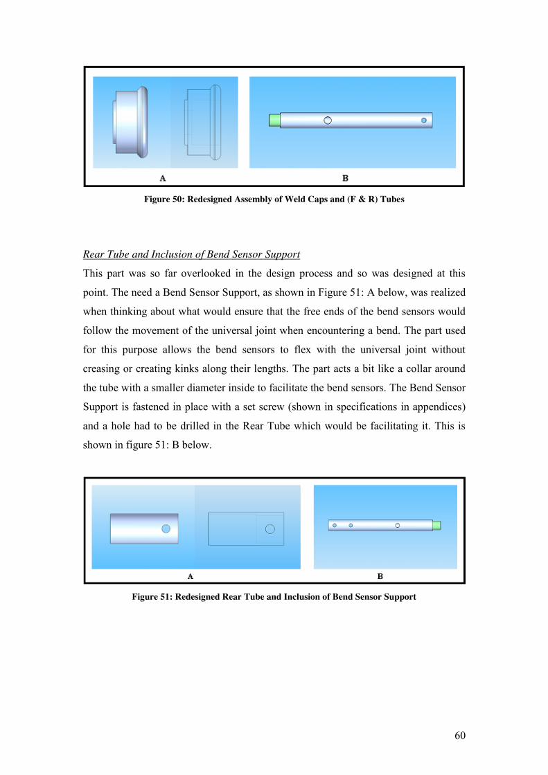
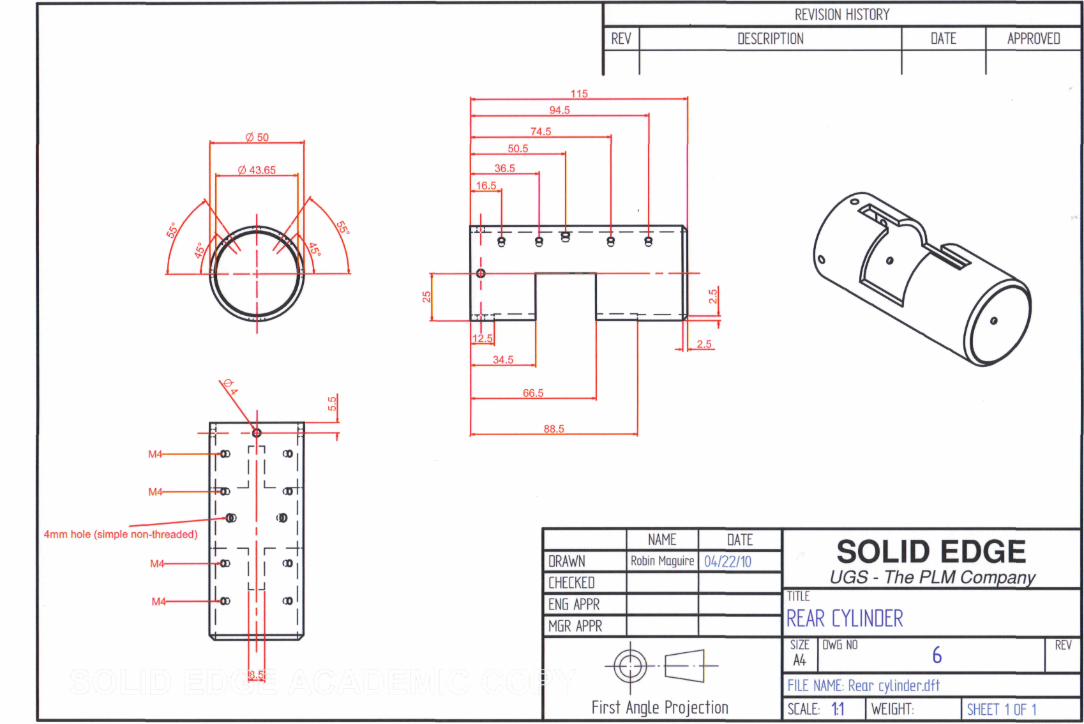
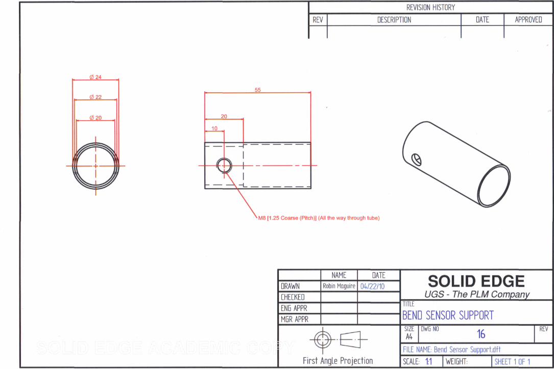
Rear Tube and Inclusion of Bend Sensor Support
This part was so far overlooked in the design process and so was designed at this
point. The need a Bend Sensor Support, as shown in Figure 51: A below, was realized
when thinking about what would ensure that the free ends of the bend sensors would
follow the movement of the universal joint when encountering a bend. The part used
for this purpose allows the bend sensors to flex with the universal joint without
creasing or creating kinks along their lengths. The part acts a bit like a collar around
the tube with a smaller diameter inside to facilitate the bend sensors. The Bend Sensor
Support is fastened in place with a set screw (shown in specifications in appendices)
and a hole had to be drilled in the Rear Tube which would be facilitating it. This is
shown in figure 51: B below.
Figure 51: Redesigned Rear Tube and Inclusion of Bend Sensor Support
61
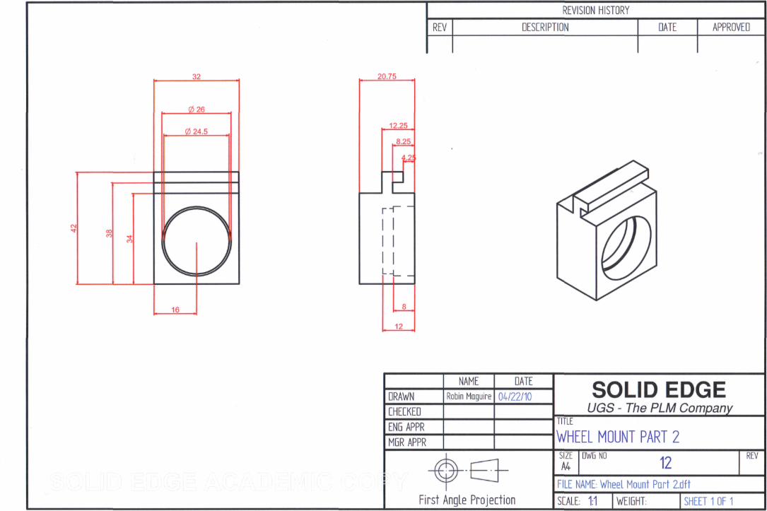
Odometer Wheel Support System
By far the most complex part in the device was the Odometer Wheel Support Part.
This housed the parts and components shown in figure 44, shown previously. The
problem with the design was that it was too complex and because of its complexity it
required far too much machining and hence increased the time to manufacture the part
and also the cost to manufacture the part. A significant amount of material would also
be wasted during the machining of the part. Figure 52: A, below, shows an assembled
view of the rear section containing the Odometer Wheel Support Part. The design
process, shown previously, was repeated and an investigation into different possible
design solutions was undertaken. The final resulting design from this investigation
including all the necessary alterations to the Rear Cylinder itself is shown in figure
52: B below. Figure 52: C shows the three main parts which replaced the previous
part. Wheel support 1 and 2, the two rectangular blocks, are slotted into the rounded
part and this is then fastened with bolts into the inside of the Rear Cylinder Diameter.
The new design requires less machining and less material than the previous design.
This leads to quicker and cheaper manufacture. The Encoder can still be sealed inside
the Wheel support within which it is stored.
Figure 52: Redesign of Odometer Wheel Support System
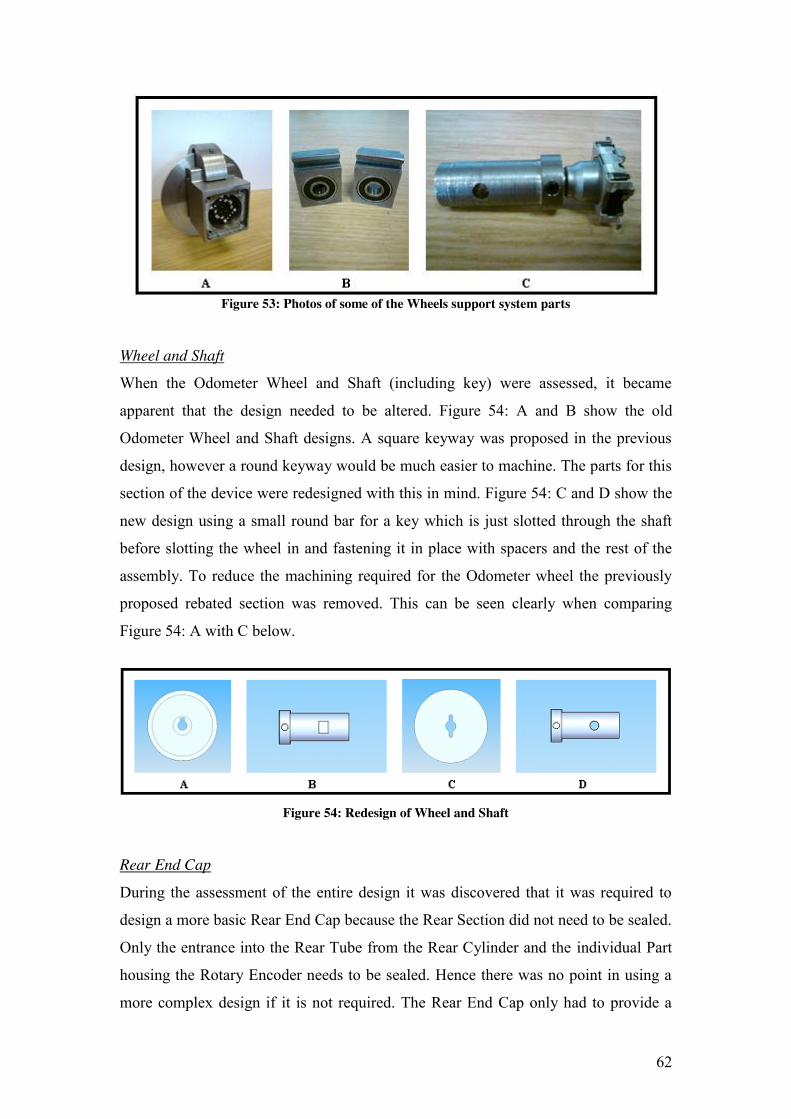
Figure 53 on the following page shows images of the some of these parts semi
assembled. Figure 53: A shows an image of the wheel support systems main
components omitting the Rear Cylinder. Figure 53: B shows the two wheels support
parts with bearings inserted and C shows the rotary encoder fastened to the shaft suing
grub screw.
62
Figure 53: Photos of some of the Wheels support system parts
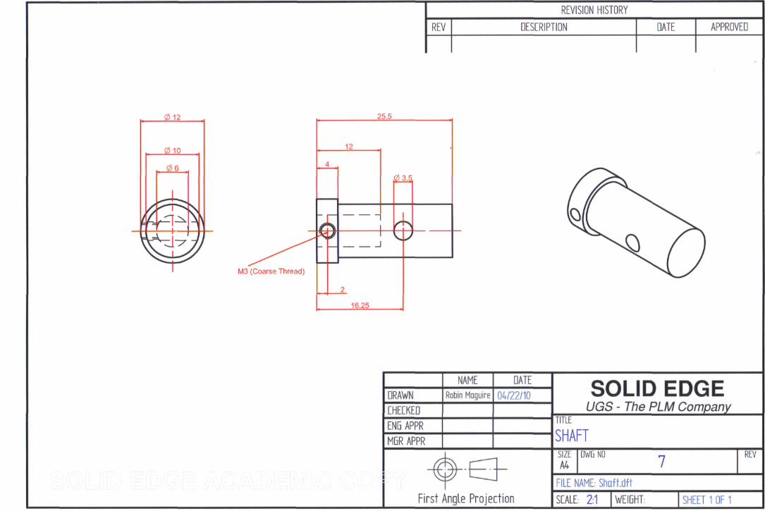
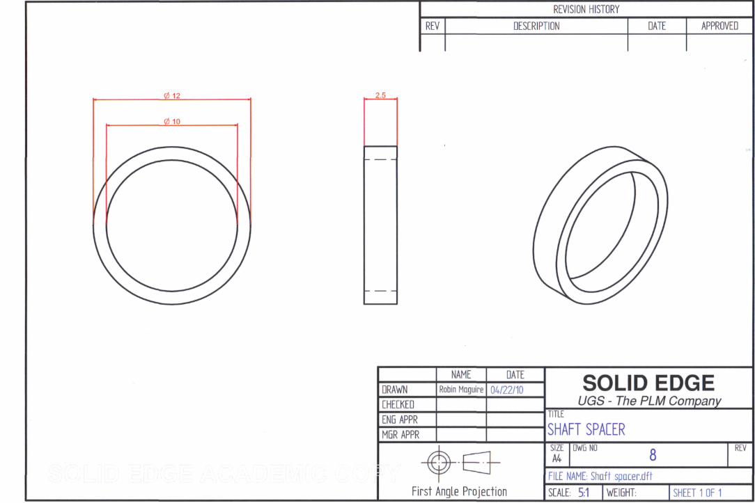
Wheel and Shaft
When the Odometer Wheel and Shaft (including key) were assessed, it became
apparent that the design needed to be altered. Figure 54: A and B show the old
Odometer Wheel and Shaft designs. A square keyway was proposed in the previous
design, however a round keyway would be much easier to machine. The parts for this
section of the device were redesigned with this in mind. Figure 54: C and D show the
new design using a small round bar for a key which is just slotted through the shaft
before slotting the wheel in and fastening it in place with spacers and the rest of the
assembly. To reduce the machining required for the Odometer wheel the previously
proposed rebated section was removed. This can be seen clearly when comparing
Figure 54: A with C below.
Figure 54: Redesign of Wheel and Shaft
Rear End Cap
During the assessment of the entire design it was discovered that it was required to
design a more basic Rear End Cap because the Rear Section did not need to be sealed.
Only the entrance into the Rear Tube from the Rear Cylinder and the individual Part
housing the Rotary Encoder needs to be sealed. Hence there was no point in using a
more complex design if it is not required. The Rear End Cap only had to provide a
63
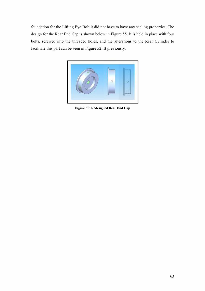
foundation for the Lifting Eye Bolt it did not have to have any sealing properties. The
design for the Rear End Cap is shown below in Figure 55. It is held in place with four
bolts, screwed into the threaded holes, and the alterations to the Rear Cylinder to
facilitate this part can be seen in Figure 52: B previously.
Figure 55: Redesigned Rear End Cap
64
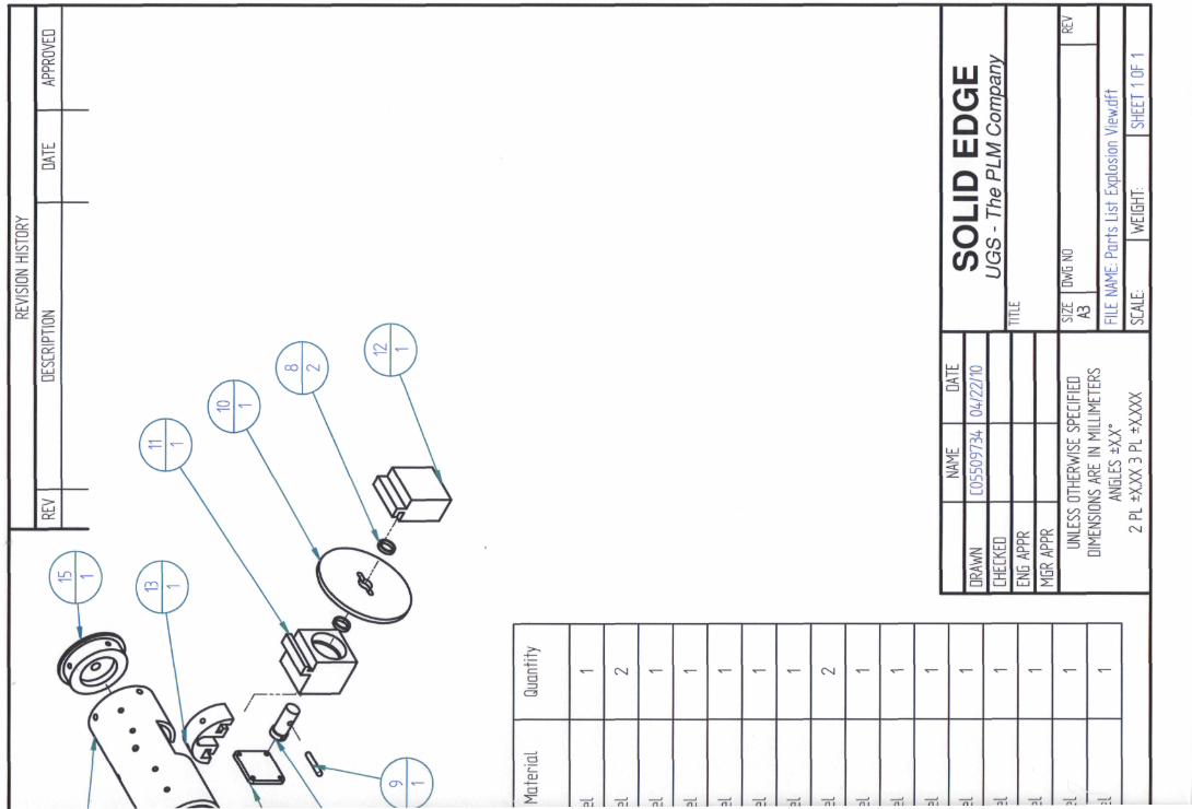
5.4 Building the Mechanical Structure for Device
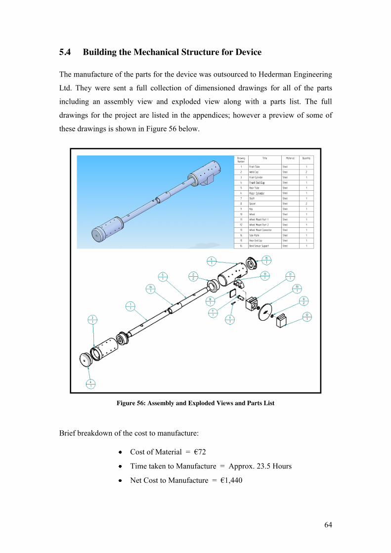
The manufacture of the parts for the device was outsourced to Hederman Engineering
Ltd. They were sent a full collection of dimensioned drawings for all of the parts
including an assembly view and exploded view along with a parts list. The full
drawings for the project are listed in the appendices; however a preview of some of
these drawings is shown in Figure 56 below.
Figure 56: Assembly and Exploded Views and Parts List
Brief breakdown of the cost to manufacture:
Cost of Material = €72
Time taken to Manufacture = Approx. 23.5 Hours
Net Cost to Manufacture = €1,440
65
5.5 Assembling & Testing Mechanical Structure
5.5.1 Assembly of Mechanical Structure The final stage of this chapter of the report involves the assembly of the manufactured
parts and premade components. All the fasteners used in the assembly are specified in
the appendices at the end of the report. The assembled mechanical structure is shown
in figure 57 below.
Figure 57: Photo of Assembled Mechanical Structure
Figure 58 below shows the front section of the fully assembled mechanical structure
of the device. Slight changes were made during manufacture to speed up the
manufacturing process. This is why thumb screws hold the Front End Cap in place as
opposed to the threads suggested in the design drawings. It is assembled similar to the
Rear End Cap.
Figure 58: Front Section of Assembled Mechanical Structure
Figure 59, on the following page, shows the rear section of the fully assembled
mechanical structure of the device. At the time when the photograph was taken only
one lifting eye bolt was available for the assembly. This is explains why the Rear End
Cap does not have a lifting eye bolt screwed into it in the images.
Figure 59: Rear Section of Assembled Mechanical Structure
66
5.5.2 Testing of Mechanical Structure The next step was to test the device in a duct to assess its performance. This took into
account the ease with which the device moved through the duct and also if any
interference between the UDBD and the duct occurred. Two tests were carried out.
The first test examined the performance of the device without the flexible conduit
attached. The second test examined the performance of the device with the flexible
conduit attached. The angle in the bend was also recorded for each using a protractor.
The test was carried out in a bend section of ducting (the same as that used by the
ESB Networks). A section of the ducting was removed to allow a visual inspection
and measurements inside the duct. The test without the flexible conduit is shown in
figure 60 below. This shows various views of the testing taking place. A clearance
measurement was taken during the test to measure the amount of clearance that the
bent part of the UDBD had in relation to its distance from the outside of the internal
diameter of the curve. This was measured approximately using a metal engineering
ruler and was recorded as 30mm. The angle of the band was recorded as
approximately 25 degrees.
Figure 60: Testing of Mechanical Structure without Conduit
67
The second test was carried out with the flexible conduit in place. It can be seen being
carried out from various different views in figure 61 below.This test was repeated the
same as the first only this time the clearance measurement was taken from the outside
corner of the conduit at the point of bending in the device had in relation to its
distance from the outside of the internal diameter of the curve. The measurement was
recorded as 21mm. The angle of the band was recorded as again approximately 25
degrees.
Figure 61: Testing of Mechanical Structure with Conduit
68
7 ELECTRONIC DEVELOPMENT
7.1 De-Bouncing Rotary Encoder
7.1.1 Theory of Debouncing The Rotary Encoder used in the device acts as a mechanical switch which when
“made” (switched on or high) sends a signal which prompts the microprocessor to
check the bend sensors. However when using mechanical switches are used as inputs,
such as this case, for digital systems (which used 1s or 0s, i.e. the microprocessor) a
phenomenon called bounce can occur. Bounce occurs when a push button (normally
open, spring return) for example, switch is pressed and released this causes spikes of
high and low voltage which is interpreted by the digital receiver as more than one
pulse, when the button might only have been pressed and released once!
Figure 62 below shows a basic switch circuit consisting of a “pull up” configuration
using a resistor. This generates an output of zero volts when the switch is pressed and
five volts through the resistor when the switch is released.
Figure 62: Switch configuration without debouncing circuit [24]
The problem with this sort of configuration is that because of the behavior explained
previously, there will not be a clean transition from one logic state to another, i.e.
transition from Logic 1 to Logic 0. There will be spikes in the transition period
between each state. This is illustrated in Figure 63 on the following page.
69
Figure 63: Behavior of a switch without a denouncing circuit [24]
As can be seen in figure 63 on the digital output line the source of error can be seen as
more than one logic 1 signals, in this case five, can be sent to the Digital receiver.
This means that the digital receiver will act as if it has the button has been pressed and
released five times. In relation to this project this would make it impossible to
accurately measure where the bends occur in the ducts and so debounce must be
eliminated in the circuit for the UDBD.
The switch could be debounced using one of two solutions. Theses possible solutions
consisted of an analog solution or a digital solution. The digital solution involved
using code written to the microcontroller to eliminate the debounce. However a dec.
counter had to be incorporated into the circuit (will be discussed in detail later in
report). This had to be used because the sampling rate would be far too great if the
microcontroller was to sample the bend sensors every 1/9th of a full rotation of the
Rotary Encoder, which is what it would do if the circuit was left unchanged. This was
unacceptable because of the speed that the microcontroller could operate at, i.e. at that
sample rate it would cause a back log in the system which was undesirable. So it was
because of the nature of the electronics to come later in the development that the
analog solution was selected.
The analog solution mainly relies on a capacitor to resist the changes of voltage on the
output. This slows down the change in output so that the unwanted high and low
pulses in the output are not recognized by the digital receiver. Figure 64, on the
following page, shows a circuit diagram for a switch configuration with a debounce
circuit.
70
Figure 64: Switch configuration with debouncing circuit [24]
The values of the resistor (R1) and the capacitor (C1) determine the response time of
the switch. The greater the value of the resistor or capacitor the better the circuit
debounces the switch. However the more the values are increased the longer it takes
for the circuit to react and generate an output. Figure 65 below shows the behavior of
a switch with a debounce circuit.
Figure 65: Behavior of a switch with a debouncing circuit [24]
It can be seen clearly in figure 65 that although the clean transition from high to low
when the button is pressed there is still some error generated when the button is
released. This error can be eliminated through the introduction of a Schmitt Trigger
into the circuit. A Schmitt Trigger will maintain its output during the passage of the
voltage through the “unknown” area in figure 65, the middle ground between High
71
and Low, until the input has reached either a High or Low voltage level.
Figure 66 below shows a debounced switch circuit now including a Schmitt trigger.
Following this is figure 67, which show the behavior of the updated circuit. [24]
Figure 66: Switch configuration with debounce circuit and Schmitt Trigger [24]
Figure 67: Switch configuration with debounce circuit and Schmitt Trigger
7.1.2 Developing Debounced Rotary Encoder Circuit Now that the solution to the problem that bounce causes in an electronic circuit has
been selected, the next step is to start to develop a specific circuit for the Rotary
Encoder. The values proposed for the design of the debouncing circuit for the UDBD
are R1 = 10 KΩ and C1 = 100nF as these are good values for general purpose
applications such as this. The Schmitt Trigger which will be used is a Texas
Instruments SN74HCT14N (listed in electronic specifications in appendices).
The first step in developing this circuit was to build the circuit on a breadboard using
jumper cables and the components mentioned previously. Once this circuit was
72
constructed it was then tested using an oscilloscope. The testing of the circuit and the
results and shown in Figure 68 below.
A B C
Figure 68: Built debounce circuit, testing and results
A 5 volt supply was hooked up to the circuit and the output from the circuit was
displayed on an oscilloscope. The test was also carried out with the debounce circuit
removed so as to compare the resulting waves shown on the oscilloscope. Figure 68:
A shows the testing of the debounce circuit with the Rotary Encoder and the resulting
wave is displayed in figure 68: B. There was no bounce viewed on the oscilloscope
what so ever. However, figure 68: C shows the wave of the Rotary Encoder with the
debounce circuit removed. There is little to no difference between the waves. This is
because the Rotary Encoder is designed to generate as little bounce as possible, far
less than the spring based pushbutton discussed earlier. The speed at which the
microprocessor will be sampling the bend sensors during operation warrants the use
of the debounce circuit and so it is included in all circuits regarding the Rotary
Encoder from this point on. Figure 69 below shows an example of a particularly bad
spring based push button switch which was used to illustrate the effect of bounce and
shows the output of the switch through the use of an oscilloscope.
Figure 69: Example of very high levels of bounce in a switch
73
7.2 Reducing Sampling Frequency of Microprocessor
If the current circuit for the Rotary Encoder was used with the microprocessor in the
current foundation design for the electronic circuit the microprocessor would be
sampling the Bends sensors every 7.32 millisecond.
(2.π.radius / 9) = distance between each sample
(2)(π)(0.035) / 9 = 0.0244m
Distance / Velocity = Time
(0.0244m) / (3.333 m/s) = 0.00732 seconds
This would create a far larger amount of information to be written and stored which
would decrease battery life and increase the complexity of processing the information
at the end of operation. This was a problem that needed a solution.
The solution was to introduce a 4-Bit Dec. Counter into the circuit to reduce the
resolution to an acceptable level. Figure 70 below illustrates how the 4-Bit Dec.
Counter reduces the sampling resolution.
Figure 70: 4-Bit Dec. Counters interaction with circuit
The 4-Bit Dec. Counter counts in binary up to 4, i.e. 0000, 0001, 0011, 0111 and
1111. For this circuit it will take in an input from the debounced Rotary Encoder and
give one high output for every 4 high signals it receives which is 8 clicks of the rotary
74
encoder (click off click on is one high signal). There are four outputs shown on the
Dec. Counter in figure 70 but only the output on the fourth pin is wired hence an
output is only sent when this pin receives an input.
The next step was to develop a circuit which incorporated the debounced Rotary
Encoder and the Dec. Counter. Figure 71 below shows the circuit diagram developed
to incorporate all of the development on the electronic circuit so far. It shows the
debounced output from the Rotary Encoder leaving the Schmitt Trigger and Entering
the Dec. Counter.
Figure 71: Circuit Diagram of debounced Encoder and Dec. Counter Figure 72 below shows the circuit constructed on a bread board and set up for testing.
The circuit was hooked up to a five volt supply and the output was measured on an
oscilloscope. The oscilloscope showed the output changing state from either high
(five volts) to low (zero volts) or low to high every eight clicks (four high signals)
from the Rotary Encoder.
Figure 72: Latest circuit constructed on breadboard
75
Now that the circuit had been constructed on breadboard and tested it could now be
build on strip-board (circuit board). Figure 73 below show the development of the
construction of the circuit on strip-board. First the design for the layout was produced
and following this the strip-board was cut down to size and any necessary breaks in
the conductive copper strips were made. The breaks in the strips were carried out
using a Stanley knife. The resulting strip-board base is shown in Figure 73: A. The
next step was to solder the components and wires onto the strip-board. Solder and a
Soldering Iron were used to perform this task. The finished circuit on the circuit board
is shown in figure 73: B and C, from underneath and above respectively.
A B C
Figure 73: Construction of debounced circuit including Dec. Counter
The last step in this process was to test the circuit to make sure all of the connections
were made (soldered) correctly and to ensure that the circuit function correctly. Figure
74 below shows the testing carried out on the circuit. A five volt battery supply was
run through the basic stamp development board to allow the power to be wired into
the breadboard. The output from the circuit went through an LED (light emitting
diode) to show visually the working function of the circuit. The LED emitted light
after eight clicks from the Rotary Encoder and continued to emit light until another
eight clicks from the Rotary Encoder which then turned it off. This proved that the
circuit was functioning correctly. The overall electronic development of the circuit for
the UDBD could now continue.
Figure 74: Testing the debounced circuit including the Dec. Counter
76
7.3 Writing Program for Microprocessor
From the moment that it was decided that the Basic Stamp Microprocessor would be
used in the device, exercise and project based learning has been ongoing in relation to
learning how to use the component and design and write code for it to use. Various
relevant exercises have been carried out throughout the projects life with the intent of
implementing them in the final electronic circuit.
The code was developed based on the Foundation Design discussed previously in the
report. Pseudo Code is listed below. This explains the code in simple terms so it can
be understood by anyone particularly people who are not familiar with programming
codes. The code used for this program was designed and written to the
Microprocessor using Parallax Basic Stamp Editor. The actual code is listed in the
appendices at the end of the report.
Pseudo Code
Switch A, refers to the switch which turns on and off the five volt supply. Switch B,
refers to the switch which makes or breaks a wire linking Pin 5 to Pin 7, this must
always be “making” the connection instead of “breaking” it before switch A is turned
on (makes its connection completing the circuit). The Pseudo code can be understood
more clearly when compared to the information in the next part of the report.
• Ensure switch B “makes” circuit
• Power is turned on (by “making” circuit using switch A)
• Check for Drive, i.e. USB Key (keeps looping until one is found)
• Pin 5 Set High (Logic 1)
• If Pin 7 receives High (from Pin 5, by “making” circuit using switch B)….
• Then Start Sampling
• If Pin 4 receives High (from Dec. Counter output)….
• Check Bend Sensor Value & write info to Data-logger & Loop
• Else Loop
• End If Pin 7 receives 0 (by “breaking” circuit using switch B)…
• Turn off power (by “breaking” circuit using switch A)
77
7.4 Integrating existing circuit with remaining Electronics
The next step in developing the overall electronic circuit was to design a circuit which
would combine all of the electronics remaining with the Rotary Encoder (Debounce +
Dec. Counter) circuit. This circuit had to also be designed to allow the code to be
applied to the circuit’s inputs and outputs. Figure 75 below shows a wiring plan on a
strip-board template of the proposed design of the layout and connections for the
circuit containing the data-logger, microprocessor and bend sensors and also
facilitates the connection of the rotary encoder input into the system. The view shown
in figure 75 is the underside of the strip board and the horizontal strips represent the
copper strips found on actual strip board. The green dots represent soldered
connections to the board and the hatched sections represent breaks in the copper
contact strips which will be broken again with a Stanley knife. The red lines represent
live five volt supply lines and the black lines represent wires going to ground.
Figure 75: Wiring plan of proposed design for circuit containing remaining electronics
After the wiring plan was completed the circuit could now be built on a section of
strip-board. All the components were connected and fastened in place using solder
and a soldering iron. Once the circuit was constructed the microprocessor then had the
78
program downloaded onto its memory which it could then run independently. Four
jumper wires which were connected to the serial inputs for the microprocessor were
included in the wiring layout. This meant that the microprocessor could be
programmed without having to remove it from its socket on the circuit board and
plugging it back into the development board, shown in green in figure 76 below
(connected to the USB to Serial Out Cable). Taking the microprocessor in and out of
sockets could lead to the structural failure of the pins which it plugs into the socket
when in use and so regularly plugging it in and out of these sockets is not desirable.
Figure 76 below shows the circuit being tested using the serial interface with a laptop
computer running Basic Stamp Editor Software. The switches mentioned in the
section on the code previously are not yet built into the circuit but they are
temporarily represented. The Power switch, switch A, is represented by making and
breaking the circuit by attaching and detaching the battery clip on the five volt
battery. The switch for making or breaking the connection between Pin 7 and Pin 5 is
represented by a male to female jumper wire connection. This starts and initiates the
program when connected and ends and closes the program when disconnected.
Figure 76: Downloading Program code and Testing Circuit
79
The testing of the circuit involved downloading the program code onto the
microprocessor and then running the program while in the debug terminal on the
laptop. This is shown in figure 77 below. The debug terminal allows the user to view
what is actually taking place in real time in relation to the microprocessor. The blue
window on the laptop screen in figure 77 shows the debug terminal. The first
paragraph of text indicates that the microprocessor checked for a drive in the data-
logger, found one and is now initializing the drive. The initialization of the drive
involves the program automatically overwriting a new data-file which will store the
information gathered during the operation of the UDBD circuit. The dotted line which
starts running across the screen represents the microprocessor continuously checking
for high (logic 1) signals from the Dec. Counter output. Once the Rotary Encoder has
been rotated to produce sixteen clicks (eight clicks to go to low logic state and eight
clicks to return to a high logic state) the microprocessor checks the bend sensor value.
This is represented on the debug terminal as the sections of text. The first bit of text
represents the microprocessor sampling. The second bit of text is a number this is the
sample number, i.e. 1 = first sample, 2 = second sample etc. and each sample is
initiated by a high signal from the Dec. Counter output. There is then an arrow in the
line of text followed by another number which represents the value from the bend
sensor. This is the end of the section of text. This section of text is repeated again
after another sixteen clicks from the Rotary Encoder but this time one of the bend
sensors was bent. This caused a change in value to the bend sensor value and hence
confirmed that the circuit was functioning correctly. The connection between Pin 5
and Pin 7 was then disconnected and the program closed and saved to the USB key
before the power was then switched off by disconnecting the battery.
Figure 77: Observing Microprocessor in test on Debug Terminal
80
7.5 Assessment of Current design
Just as the Mechanical Structure in the Mechanical Development chapter previously
was assessed, so to must the current design of the electronic circuit. It was assessed to
ensure that it would function correctly and integrate effectively into the Mechanical
Structure.
Since the electronic development coincided with the mechanical development, fixed
dimensional constraints were not clearly set out; only an approximation at the
beginning was established. At this stage a definite dimensional volume is available
from the finished working drawings for the mechanical structure for the UDBD and
so the electronics were assessed against this to see if they would fit inside the Front
Cylinder. It was discovered that the layout of the components would have to be
redesigned to ensure that the electronics could be integrated into the mechanical
structure effectively because the current design would not fit inside the UDBD. Also
the redesigned layout of the circuit would include two switches to replace the
previous representative switch methods and an LED for each to visually indicate the
switches status. Figure 78 below shows the redesigned layout of the electronic circuit.
The color code explained previously applies once more with the addition of blue
wires for logic in/out wires and resistors and capacitors in black. The switches and
LED are not included in this schematic as they will be in-line wired.
Figure 78: Redesigned layout for electronic circuit
81
Figure 79 below shows the strip-board prepared for soldering. All the necessary
breaks in the copper contact strips have been made with a Stanley knife.
Figure 79: Strip-board prepared for soldering
Figure 80 below shows the completed electronic circuit with the Rotary Encoder and
Bend Sensors outside of the image. This was then tested on a computer using the
previous method, before moving on to the next stage of the project.
-All holes drilled perpendicular tocentral axis of cylinder are M4
DRAWNEHECKEDENG APPRMGR APPR
NAMERobin Maguire
DATE04/22/10
First Angle Projection
SOLID EDGEUGS - The PLM Company
TITLE
FRONT CYLINDERSIZEA4
DWG NO 3 REV
FILE NAME: Front Eylinder.dftSEALE: 1:2 WEIGHT: SHEET 1 OF 1
REVISION HISTORYREV DESCRIPTION DATE APPROVED
054
M48 (X4)
21
12.5
9
r
_ J11
1
^8\X
'SURFACE TO BE KNURLED
DRAWNEHECKEDENG APPRMGR APPR
NAMERobin Maguire
DATE04/22/10
First Angle Projection
SOLID EDGEUGS - The PLM Company
TITLE
FRONT END CAPSIZE DWG NOA4
, REVH-
FILE NAME; Front End Cnp.dftSCALE: 1:1 WEIGHT: SHEET 1 OF 1
REVISION HISTORYREV DESCRIPTION DATE APPROVED
020
017M8 [1.25 Coarse (Pitch)] (All the way th -ough tube)
M16 [2.0 Coarse (Pitch)]
M8 [1.25 Coarse (Pitch)] (All the way through tube)
DRAWNEHECKEDENG APPRMGR APPR
NAMERobin Maguire
DATE04/22/10
First Angle Projection
SOLID EDGEUGS - The PLM Company
TITLE
REAR TUBESIZEA4
DWG 5 REV
FILE NAME: Rear Tube.dftSCALE: 1:1 WEIGHT: SHEET 1 OF
050
.-threaded)
\
,*IU^
1-f- -i•fTi
\
u1
>r
._
EJ
L<ffl<9>
r 4cn
en
T
REVISION HISTORYREV DESCRIPTION
11594.5
74.550.5
36.516.5
e e
.U---12.5
34.5
66.5
3.5
2.5
DRAWNCHECKEDENG APPRMGR APPR
NAMERobin Maguire
DATE04/22/10
First Angle Projection
DATE APPROVED
SOLID EDGEUGS - The PLM Company
TITLE
REAR CYLINDERSIZEA4
DWG NO 6 REV
FILE NAME: Rear cylinder.dftSEALE: 1:1 WEIGHT; SHEET 1 OF
REVISION HISTORYREV DESCRIPTION DATE APPROVED
g) 12
M3 (Coarse Thread)
25.5
12
.0 3.5.
J
16.25
DRAWNEHEEKEDENG APPRMQR APPR
NAMERobin Maguire
DATE04/22/10
First Angle Projection
SOLID EDGEUGS - The PLM Company
TITLE
SHAFTSIZE DWG NO „A4 /
FILE NAME; Shaft.dftSEALE; 2:1 WEIGHT;
REV
SHEET 1 OF 1
REVISION HISTORYREV DESERIPTION DATE APPROVED
2.5
•
DRAWNEHECKEDENG APPRMGR APPR
NAMERobin Maguire
DATE04/22/10
First Angle Projection
SOLID EDGEUGS - The PLM Company
TITLE
SHAFT SPACERSIZE DWG NOA4 8
FILE NAME: Shaft spacer.dftSEALE: 5:1 WEIGHT: SHEET 1 OF 1
REVISION HISTORYREV DESERIPT10N DATE APPROVED
03.5
R1.75
22
DRAWNEHEEKEDENG APPRMGR APPR
NAMERobin Mopire
DATE04/22/10
First Angle Projection
SOLID EDGEUGS - The PLM Company
TITLE
KEYSIZEA4
DWG REV
FILE NAME: Key.dftSEALE; 5:1 WEIGHT; SHEET 1 OF
REVISION HISTORYREV DESCRIPTION DATE APPROVED
070
DRAWNEHEEKEDENG APPRMGR APPR
NAMERobin Mciguire
DATE04/22/10
First Angle Projection
SOLID EDGEUGS - The PLM Company
TITLE
WHEELSIZE DWG NO Ar.A4 10
FILE NAME; WheeldftSEALE: 1:1 WEIGHT:
REV
SHEET 1 OF 1
REVISION HISTORYREV DESCRIPTION DATE APPROVED
1.54.5
32
26
24.5
16
'M2.5
30.75
12.25
8.25
21
DRAWNEHEEKEDENG APPRMGR APPR
NAMERobin Maguire
DATE04/22/10 SOLID EDGE
UGS - The PLM CompanyTITLE
WHEEL MOUNT PART 1SIZEA4
DWG11
REV
FILE NAME; Wheel Mount Part 1.dftFirst Angle Projection SEALE: 1:1 WEIGHT: SHEET 1 OF 1
REVISION HISTORYREV DESCRIPTION DATE APPROVED
026
024.5
i• • >
16
20.75
12.25
8.25
12
DRAWNCHEEKEDENG APPRMGR APPR
NAMERobin Maguire
DATE04/22/10 SOLID EDGE
UGS - The PLM CompanyTITLE
WHEEL MOUNT PART 2
First Angle Projection
SIZEA4
DWG 12 REV
FILE NAME: Wheel Mount Part ZdftSCALE: 1:1 WEIGHT: SHEET 1 OF 1
M4 (Depth 9mm from surface of part)
REVISION HISTORYREV DESCRIPTION
15
R
DATE APPROVED
5.32
17.58
13.32
9,32
I I I IDRAWNCHECKEDENG APPRMGR APPR
NAMERobin Maguire
DATE04/22/10
First Angle Projection
SOLID EDGEUGS - The PLM Company
TITLE
WHEEL MOUNT CONNECTORSIZEA4
DWG 13 REV
FILE NAME; Wheel mount connector.dftSCALE: 1:1 WEIGHT: SHEET 1 OF 1
REVISION HISTORYREV DESERIPTIDN DATE APPROVED
05
02.5
coCN
"I
V
(
\
:
-
Ii-
-
*?
)
>2
*
H- --&s26
•
^
3
ij
~T
1.5
DRAWNEHEEKEDENG APPRMGR APPR
NAMERobin Maguire
DATE04/22/10
First Angle Projection
SOLID EDGEUGS - The PLM Company
TITLE
SIDE PLATESIZEA4
DWG NO 14 REV
FILE NAME; Side plate.dftSEALE: 2:1 WEIGHT: SHEET 1 OF 1
REVISION HISTORYREV DESCRIPTION DATE APPROVED
05013
mi
7.5
• M4 Gam Deep)
DRAWNCHEEKEDENG APPRMGR APPR
NAMERobin Maguire
DATE04/22/10 SOLID EDGE
UGS - The PLM CompanyTITLE
REAR END EARSIZEA4
DWG 15 REV
FILE NAME: Rear End Cap.dftFirst Angle Projection SCALE: 1:1 WEIGHT: SHEET 1 OF 1
REVISION HISTORYREV DESERIPTION DATE APPROVED
024
M8 [1.25 Coarse (Pitch)] (All the way through tube)
DRAWNEHEEKEDENG APPRMGR APPR
NAMERobin Maguire
DATE04/22/10 SOLID EDGE
UGS - The PLM CompanyTITLE
BEND SENSOR SUPPORTSIZEA4
DWG NO 16 REV
FILE NAME: Bend Sensor Support.dftFirst Angle Projection SEALE; 1:1 WEIGHT: SHEET 1 OF
118
III - PROGRAM CODE
119
============================================================= ' ' File...... DataloggerDemoV1.0.bs2 ' Purpose... UDBD ' Author.... Robin Maguire ' E-mail.... ' Started... ' Updated... 01/04/2010 ' ' $STAMP BS2 ' $PBASIC 2.5 ' ' ============================================================= ' -----[ Program Description ]--------------------------------------------- ' -----[ I/O Definitions ]------------------------------------------------- Sensor PIN 1 ' Light Sensor Or Thermistor TX PIN 11 ' Transmit Data --> 27937.4 (RXD) RTS PIN 13 ' Request To Send --> 27937.6 (CTS) RX PIN 12 ' Receive Data <-- 27937.5 (TXD) CTS PIN 9 ' Clear To Send <-- 27937.2 (RTS) ' -----[ Constants ]------------------------------------------------------- Baud CON 84 ' Serial Baud Rate 9600 bps (BS2) NumSamples CON 10 ' Number Of Samples To Log ' -----[ Variables ]------------------------------------------------------- buffer VAR Byte(15) ' Input Buffer index VAR Byte ' Index Variable ioByte VAR Byte ' Input/Output Storage counter VAR Word ' counter result VAR Word ' Sensor RCTIME Result work VAR Word ' Work Variable flag VAR Bit ' Event Status Flag flag2 VAR Bit ' Event Status Flag 2 ' -----[ Initialization ]--------------------------------------------------
120
DEBUG CLS, "Memory Stick Datalogger Demo V1.0", CR, CR, "Initializing..." PAUSE 200 ' Allow Time To Settle HIGH TX ' Initialize Transmit Line LOW RTS ' Take Vinculum Out Of Reset PAUSE 600 ' Allow Time To Settle DEBUG "Done!", CR, "Synchronizing..." DO SEROUT TX\CTS, Baud, ["E", CR] ' Sync Command Character GOSUB Get_Data ' Get Response PAUSE 250 LOOP UNTIL ioByte = $0D ' Wait For Carriage Return DO SEROUT TX\CTS, Baud, ["e", CR] ' Sync Command Character GOSUB Get_Data ' Get Response PAUSE 250 LOOP UNTIL ioByte = $0D ' Wait For Carriage Return ' -----[ Program Code ]---------------------------------------------------- Main: DEBUG "Done", CR, "Switching to Short Command Mode..." SEROUT TX\CTS, Baud, ["SCS", CR] ' Switch To Short Command Mode GOSUB Get_Data ' Purge Receive Buffer DEBUG "Done!", CR, "Waiting for Memory Stick..." Check_Drive: DO SEROUT TX\CTS, Baud, [CR] ' Prompt Device For Status GOSUB Get_Data ' Purge Receive Buffer IF buffer(0) = ">" THEN ' Check For Ready Prompt EXIT ' If Ready Then Exit Loop ELSEIF buffer(0) = "N" AND buffer(1) = "D" THEN DEBUG "." ' Device Ready But No Memory Stick ELSEIF buffer(0) = "D" AND buffer(1) = "D" AND flag = 0 THEN DEBUG "Connected!", CR, "Accessing..." flag = 1 ' Memory Stick Ready ELSE DEBUG "." ENDIF PAUSE 250 ' Command Retry Delay LOOP DEBUG "Ready!", CR Open_File:
121
DEBUG "Opening Data File..." ' First Delete File SEROUT TX\CTS, Baud, [$07, $20, "datafile.txt", CR] GOSUB Get_Data ' Purge Receive Buffer ' Then Create File SEROUT TX\CTS, Baud, [$09, $20, "datafile.txt", CR] GOSUB Get_Data ' Purge Receive Buffer counter = 0 DEBUG "Open!", CR, CR, "Ready to Write Data...", CR flag2 = 1 HIGH 6 Write_Data: PAUSE 30 IF IN7 = 1 THEN ' Are we in sampling mode? IF IN2 = 1 THEN ' Rotary encoder IF flag2 = 1 THEN flag2 = 0 counter = counter + 1 HIGH Sensor PAUSE 10 ' Wait 1 ms RCTIME Sensor, 1, result ' Measure Discharge Time DEBUG DEC5 counter, " unit ", " --> ", DEC5 result, CR ' Display Results SEROUT TX\CTS, Baud, [$08, $20, $00, $00, $00, $0D, CR, DEC5 counter, ",", DEC5 result, CR, LF, CR] LOW Sensor PAUSE 5 ' Write Results/Delay GOSUB Get_Data ' Purge Receive Buffer GOTO Write_Data ELSE DEBUG "." PAUSE 5 GOTO Write_Data ENDIF
122
ELSEIF IN2 = 0 THEN flag2 = 1 DEBUG "." PAUSE 5 GOTO Write_Data ELSE PAUSE 5 GOTO Write_Data ENDIF ELSE PAUSE 100 GOTO Close_File ENDIF Close_File: DEBUG "Closing Data File...Program Complete!" SEROUT TX\CTS, Baud, [$0A, $20, "datafile.txt", CR] GOSUB Get_Data ' Purge Receive Buffer STOP ' -----[ Subroutines ]----------------------------------------------------- Get_Data: index = 0 ' Reset Index Pointer DO ' Receive Data SERIN RX\RTS, Baud, 100, Timeout, [ioByte] buffer(index) = ioByte ' Add Received Byte To Buffer index = index + 1 ' Increment Index Pointer IF index > 14 THEN Timeout ' Check For Overflow LOOP Timeout: RETURN
123
IV – FASTENER &
MISCELLANEOUS
SPECIFICATIONS
124
Bolts For Side Plate (M2.5, L = 10mm) (QUANTITY = 4) https://www.misumi-ec.com/euro/egrmen/ItemDetail/10300244420.html
Nuts for Fastening Front & Rear Tubes to Weld Caps (M16, Right Hand Thread, 1018 Steel, JIS Class 3) (QUANTITY = 2) https://www.misumi-ec.com/euro/egrmen/ItemDetail/10300250540.html
Screw to hold Encoder shaft in line with rotating shaft (M3, L = 5mm, flat end) (QUANTITY = 1) https://www.misumi-ec.com/euro/egrmen/ItemDetail/10300248260.html
Tapped Compression spring alignment washers, to screw on suspension screws (M4) (QUANTITY = 12) https://www.misumi-ec.com/euro/egrmen/ItemDetail/10300268650.html
Domed nuts to fasten M4 Suspension screws on the inside surface of cylinders (M4) (QUANTITY = 12) https://www.misumi-ec.com/euro/egrmen/ItemDetail/10300251150.html