Department of Mechanical Engineering University of Victoria Victoria, BC, Canada
Abstract— Vision-based control of unmanned aerial vehicles has potential to increase their autonomy and safety during flight and landing, thus increasing their prevalence in various industries. This paper presents the design and development of the hardware for a vision-based autopilot. The aim was to develop a modular, low-cost system that consists of non-proprietary components. The main components are a custom switching module that interfaces between the autopilot and the RC receiver, a single-board computer for image analysis and control, and an autopilot for low-level servomotor control. Hardware-in-the-loop tests show that the switching module is capable of switching between the manual and vision-based control input. It can also return the control of the UAV to the operator when needed.
The civilian use of unmanned aerial vehicles (UAVs) has experienced rapid growth over the past years. Current applications include surveying, forestry, law enforcement, search and rescue, and wildlife monitoring. Numerous other applications remain yet to be discovered as UAV performance and reliability improve, but the UAV industry is projected to continue to grow.
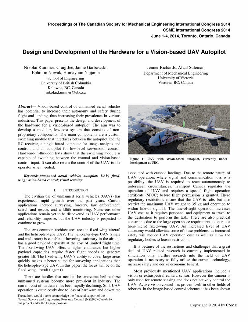
The two common architectures are the fixed-wing aircraft and the helicopter-type UAV. The helicopter-type UAV (single and multirotor) is capable of hovering stationary in the air and has a good payload capacity at the cost of limited flight time. The fixed-wing UAV offers a higher endurance, but higher payload capacities require faster flight speeds to generate greater lift. The fixed-wing UAV’s ability to cover large areas quickly makes it better suited for surveying applications than the helicopter-type UAV. In this paper, the focus will be on the fixed-wing aircraft (Figure 1).
There are hurdles that need to be overcome before these unmanned systems become more prevalent in industry. The current cost of hardware has been rapidly declining. Still, UAV operation is quite costly due to loss of hardware and downtime
associated with crashed landings. Due to the remote nature of UAV operation, where signal and communication loss is a possibility, the UAV is required to react autonomously to unforeseen circumstances. Transport Canada regulates the operation of UAV and requires a special flight operation certificate (SFOC) before flight permission is granted. These regulatory restrictions ensure that the UAV is safe, but also restrict the maximum UAV weight to 35 kg and operation to within line-of sight[1]. The line-of-sight operation increases UAV cost as it requires personnel and equipment to travel to the destination to perform the task. There are also practical constraints due to the large open space requirement to operate a (non-micro) fixed-wing UAV. An increased level of UAV autonomy would alleviate some of these problems, as increased safety will reduce UAV operation cost as well as allow the regulatory bodies to loosen restriction.
It is because of the restrictions and challenges that a great deal of UAV related research is currently implemented in simulation only. Further research into the field of UAV operation is necessary to fully utilize the current technology, increase safety and derive economic benefit.
Most previously mentioned UAV applications include a vision or extraspectral camera sensor. However the camera is only used for remote sensing and does not actively control the UAV. Active vision control has proven itself in other fields of robotics. In the image-based control schemes it has been shown
The authors would like to acknowledge the financial support of the Natural Science and Engineering Research Council (NSERC) Canada for this project under the Engage program.
Figure 2: Hardware Connection Diagram for the Vision Autopilot
that positioning will converge to the desired position, regardless of onboard sensor accuracy and in the presence of camera calibration errors[2]. The addition of a vision-based control has great potential to increase the autonomy of the UAV, due to decreased reliance on onboard positioning sensors. Vision-based control can be categorized into feature tracking and optical flow. Optical-flow sensors have been used for obstacle avoidance in flight [3]and landing [4]. In this paper the focus is on feature tracking-based methods, due to the large pool of potential features to choose from, such as point features, line features and image moments.
Visual servoing is the practice of controlling a robotic system using vision sensor information as feedback. It has been extensively researched for robot arms[2], mobile robots and quadrotor helicopters[5][6] with improvements to positioning accuracy. Visual servoing of fixed-wing aircraft has received limited attention. Extensive research deals with information that can be extracted from images to augment onboard sensors, such as horizon estimation in [7], height-above ground estimation in [4]. Reference [8] uses visual servoing to control heading for skid-to-turn manoeuvres for inspection tasks, which were tested in simulations. Vision-based control methods for UAV are often implemented in simulation or in offline analysis on images captured during flight. Major challenges associated with vision-based fixed-wing control include nonlinear equations of motion, coupled attitude and velocity dynamics, lack of readily available hardware and the practical requirements of a suitable testing area.
A prominent area of research for vision-based fixed-wing control is automated landing. Landing accounts for a significant percentage of damage to UAVs[9]. Manual landing, performed by trained human pilots is susceptible to human error[9][10]. Partially responsible is the third person view that the pilot has of the UAV during landing. Landing automation has great potential to reduce UAV operational cost and increase safety to ground personnel. The motivation behind the work presented in this paper is fuelled by landing automation.
Controlled collision landings are popular for small fixed- wing UAVs. The authors in [10] present a vision-based landing method with a large coloured net. The method was tested in experiments and the image processing was done on a ground station computer, which makes the system highly vulnerable to signal loss. Controlled collision landing with a large inflatable airbag, addresses some problems with the net based landing method, as landing can occur from any heading direction. Airbag landing has been implemented in simulation in [11] and in experiments in [9] for a blended-wing body UAV with onboard image processing.
The presented literature shows research aimed at increasing autonomy and safety of UAVs. However the algorithms are either implemented in simulation only or are implemented on a custom created vision autopilot system, interfacing on custom designed boards. Quadrotor helicopters have the PIXHAWK vision autopilot[12], but to the best of the author’s knowledge no such system exists for fixed-wing aircraft. The availability of a standard vision-based autopilot can fuel further research into UAV control. In this paper, the design and development of a vision-based autopilot is presented, to assist the creation of a
robust and reliable vision-based autopilot and to reduce the time from algorithm development to implementation.
A. Design Requirements
This section summarizes the guidelines for development of the vision-based autopilot. The two main areas of development should be the autopilot hardware and a corresponding hardware-in-the-loop (HIL) system that allows the safe testing of algorithms, prior to the implementation on a real UAV. A summary of design requirements for the autopilot follows. The system should be:
• capable of onboard processing of images due to potential for signal loss.
• inexpensive to reduce cost associated with potential crashes.
• robust enough to detect if the image processing computer has become unresponsive.
• return manual control to the operator at any time.
• modular to facilitate improvements on each subsystem.
• Assembled using off-the-shelf components, where possible, to reduce development cost and time.
• lightweight enough to be portable by a small UAV.
B. Contributions
This research focuses on fixed-wing UAVs, in view of their increased range and endurance. The progress on the development of a vision-based autopilot for testing vision-based algorithms is presented. An overview of the proposed system is shown in Figure 2.
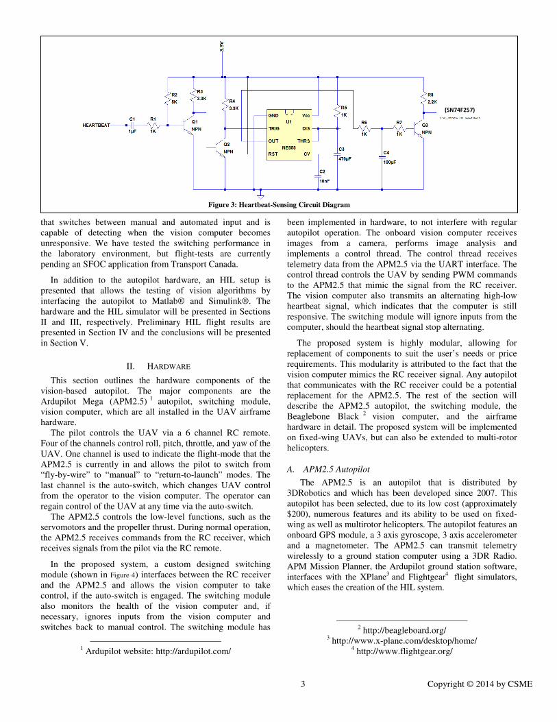
The three major components of the vision autopilot are a vision computer, an autopilot and a switching module. Figure 3 presents the proposed circuit diagram for a switching module
that switches between manual and automated input and is capable of detecting when the vision computer becomes unresponsive. We have tested the switching performance in the laboratory environment, but flight-tests are currently pending an SFOC application from Transport Canada.
In addition to the autopilot hardware, an HIL setup is presented that allows the testing of vision algorithms by interfacing the autopilot to Matlab® and Simulink®. The hardware and the HIL simulator will be presented in Sections II and III, respectively. Preliminary HIL flight results are presented in Section IV and the conclusions will be presented in Section V.
II. HARDWARE
This section outlines the hardware components of the vision-based autopilot. The major components are the Ardupilot Mega (APM2.5) 1 autopilot, switching module, vision computer, which are all installed in the UAV airframe hardware.
The pilot controls the UAV via a 6 channel RC remote. Four of the channels control roll, pitch, throttle, and yaw of the UAV. One channel is used to indicate the flight-mode that the APM2.5 is currently in and allows the pilot to switch from “fly-by-wire” to “manual” to “return-to-launch” modes. The last channel is the auto-switch, which changes UAV control from the operator to the vision computer. The operator can regain control of the UAV at any time via the auto-switch.
The APM2.5 controls the low-level functions, such as the servomotors and the propeller thrust. During normal operation, the APM2.5 receives commands from the RC receiver, which receives signals from the pilot via the RC remote.
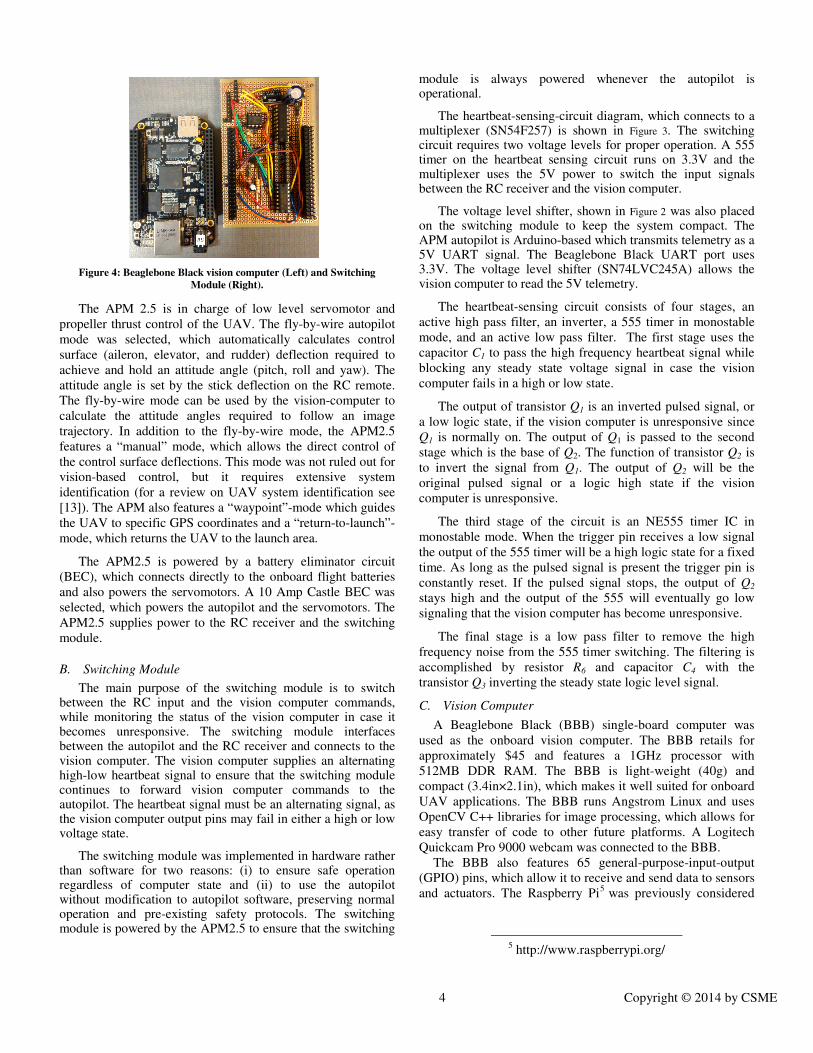
In the proposed system, a custom designed switching module (shown in Figure 4) interfaces between the RC receiver and the APM2.5 and allows the vision computer to take control, if the auto-switch is engaged. The switching module also monitors the health of the vision computer and, if necessary, ignores inputs from the vision computer and switches back to manual control. The switching module has
1 Ardupilot website: http://ardupilot.com/
been implemented in hardware, to not interfere with regular autopilot operation. The onboard vision computer receives images from a camera, performs image analysis and implements a control thread. The control thread receives telemetry data from the APM2.5 via the UART interface. The control thread controls the UAV by sending PWM commands to the APM2.5 that mimic the signal from the RC receiver. The vision computer also transmits an alternating high-low heartbeat signal, which indicates that the computer is still responsive. The switching module will ignore inputs from the computer, should the heartbeat signal stop alternating.
The proposed system is highly modular, allowing for replacement of components to suit the user’s needs or price requirements. This modularity is attributed to the fact that the vision computer mimics the RC receiver signal. Any autopilot that communicates with the RC receiver could be a potential replacement for the APM2.5. The rest of the section will describe the APM2.5 autopilot, the switching module, the Beaglebone Black 2 vision computer, and the airframe hardware in detail. The proposed system will be implemented on fixed-wing UAVs, but can also be extended to multi-rotor helicopters.
A. APM2.5 Autopilot
The APM2.5 is an autopilot that is distributed by 3DRobotics and which has been developed since 2007. This autopilot has been selected, due to its low cost (approximately $200), numerous features and its ability to be used on fixed-wing as well as multirotor helicopters. The autopilot features an onboard GPS module, a 3 axis gyroscope, 3 axis accelerometer and a magnetometer. The APM2.5 can transmit telemetry wirelessly to a ground station computer using a 3DR Radio. APM Mission Planner, the Ardupilot ground station software, interfaces with the XPlane3 and Flightgear4 flight simulators, which eases the creation of the HIL system.
Figure 4: Beaglebone Black vision computer (Left) and Switching
Module (Right).
The APM 2.5 is in charge of low level servomotor and
propeller thrust control of the UAV. The fly-by-wire autopilot mode was selected, which automatically calculates control surface (aileron, elevator, and rudder) deflection required to achieve and hold an attitude angle (pitch, roll and yaw). The attitude angle is set by the stick deflection on the RC remote. The fly-by-wire mode can be used by the vision-computer to calculate the attitude angles required to follow an image trajectory. In addition to the fly-by-wire mode, the APM2.5 features a “manual” mode, which allows the direct control of the control surface deflections. This mode was not ruled out for vision-based control, but it requires extensive system identification (for a review on UAV system identification see [13]). The APM also features a “waypoint”-mode which guides the UAV to specific GPS coordinates and a “return-to-launch”-mode, which returns the UAV to the launch area.
The APM2.5 is powered by a battery eliminator circuit (BEC), which connects directly to the onboard flight batteries and also powers the servomotors. A 10 Amp Castle BEC was selected, which powers the autopilot and the servomotors. The APM2.5 supplies power to the RC receiver and the switching module.
B. Switching Module
The main purpose of the switching module is to switch between the RC input and the vision computer commands, while monitoring the status of the vision computer in case it becomes unresponsive. The switching module interfaces between the autopilot and the RC receiver and connects to the vision computer. The vision computer supplies an alternating high-low heartbeat signal to ensure that the switching module continues to forward vision computer commands to the autopilot. The heartbeat signal must be an alternating signal, as the vision computer output pins may fail in either a high or low voltage state.
The switching module was implemented in hardware rather than software for two reasons: (i) to ensure safe operation regardless of computer state and (ii) to use the autopilot without modification to autopilot software, preserving normal operation and pre-existing safety protocols. The switching module is powered by the APM2.5 to ensure that the switching
module is always powered whenever the autopilot is operational.
The heartbeat-sensing-circuit diagram, which connects to a multiplexer (SN54F257) is shown in Figure 3. The switching circuit requires two voltage levels for proper operation. A 555 timer on the heartbeat sensing circuit runs on 3.3V and the multiplexer uses the 5V power to switch the input signals between the RC receiver and the vision computer.
The voltage level shifter, shown in Figure 2 was also placed on the switching module to keep the system compact. The APM autopilot is Arduino-based which transmits telemetry as a 5V UART signal. The Beaglebone Black UART port uses 3.3V. The voltage level shifter (SN74LVC245A) allows the vision computer to read the 5V telemetry.
The heartbeat-sensing circuit consists of four stages, an active high pass filter, an inverter, a 555 timer in monostable mode, and an active low pass filter. The first stage uses the capacitor C1 to pass the high frequency heartbeat signal while blocking any steady state voltage signal in case the vision computer fails in a high or low state.
The output of transistor Q1 is an inverted pulsed signal, or a low logic state, if the vision computer is unresponsive since Q1 is normally on. The output of Q1 is passed to the second stage which is the base of Q2. The function of transistor Q2 is to invert the signal from Q1. The output of Q2 will be the original pulsed signal or a logic high state if the vision computer is unresponsive.
The third stage of the circuit is an NE555 timer IC in monostable mode. When the trigger pin receives a low signal the output of the 555 timer will be a high logic state for a fixed time. As long as the pulsed signal is present the trigger pin is constantly reset. If the pulsed signal stops, the output of Q2 stays high and the output of the 555 will eventually go low signaling that the vision computer has become unresponsive.
The final stage is a low pass filter to remove the high frequency noise from the 555 timer switching. The filtering is accomplished by resistor R6 and capacitor C4 with the transistor Q3 inverting the steady state logic level signal.
C. Vision Computer
A Beaglebone Black (BBB) single-board computer was used as the onboard vision computer. The BBB retails for approximately $45 and features a 1GHz processor with 512MB DDR RAM. The BBB is light-weight (40g) and compact (3.4in×2.1in), which makes it well suited for onboard UAV applications. The BBB runs Angstrom Linux and uses OpenCV C++ libraries for image processing, which allows for easy transfer of code to other future platforms. A Logitech Quickcam Pro 9000 webcam was connected to the BBB.
The BBB also features 65 general-purpose-input-output (GPIO) pins, which allow it to receive and send data to sensors and actuators. The Raspberry Pi5 was previously considered
Figure 5: Hardware-in-the-loop setup to test vision-based UAV
control algorithms.
for vision computer application, but was slower than the BBB and had fewer GPIO pins.
The BBB is powered by a portable 5V, 2600mAh universal backup battery charger through the micro USB port. The BBB consumes approximately 210-460mA, depending on the processor load and peripheral devices that are connected, which gives the BBB well over 4 hours of operation time on a single charge.
The vision computer runs three threads in parallel, the control, the image analysis, and the heartbeat thread. If the vision computer becomes unresponsive, the alternating heartbeat will stop and the switching module will ignore any vision computer commands.
The heartbeat thread checks if the auto-switch has been engaged. The signal from the auto-switch is send by the RC receiver. The RC receiver output signal is a 5V square wave with a period of 20ms and a duty cycle between 1ms and 2ms. The output was converted from a digital to an analog signal via a first-order RC filter consisting of a 4.7kΩ resistor and a 47μF capacitor. The resulting analog signal is read by the vision computer to detect if the auto-switch is engaged. Once detected, the vision computer starts alternating the heartbeat signal from high to low in a loop.
The image analysis thread collects images from the webcam and detects target features. The feature locations are forwarded to the control thread. The control thread reads the autopilot telemetry information through the UART interface and receives the target information from the image analysis thread. The control thread implements a visual servoing controller and calculates the required UAV attitude angles. The control thread sends the mimicked RC receiver signals over the vision computer’s PWM-capable pins to achieve the desired attitude.
D. Airframe
The EPP-FPV airframe by Hobbyking was selected. The airframe (shown in Figure 1) weighs approximately 3kg when loaded with the batteries, autopilot, switching module and vision computer. The airframe was selected as it was designed for first-person-view (FPV) flight; therefore it features additional interior space for onboard electronics. The airframe’s pusher configuration (rear facing propeller) makes it well suited for mounting a forward facing camera.
A 35-36B 1400kV brushless DC motor, powered by a Turnigy 45Amp electric speed controller (ESC), drives a 10 inch propeller. The control surfaces are moved by four 9 gram analog servomotors. The airframe contains two 2200mAh Lithium polymer batteries, which power the motor ESC and the servo/autopilot BEC. Based on the batteries, the approximate flight time is 20-30 minutes.
III. HARDWARE IN THE LOOP SYSTEM
Successful simulation results are required prior to implementation of a control scheme on a real UAV. These
tests can be performed via an HIL setup (shown in Figure 5). The setup was used to test the switching module and will be used for future research on vision-based UAV control schemes. The HIL setup consists of two computers: the simulator computer and the HIL vision computer, which are explained in the rest of this section.
A. Simulator Computer
The simulator computer runs the APM Mission Planner, which connects to the XPlane 9 flight simulator. The flight simulator provides response telemetry of the simulated UAV due to the APM2.5 input, as well as image data to the HIL vision computer. The simulated UAV can be tuned to react similar to the real UAV by examining flight test data. XPlane sends telemetry data over the network, which is collected by the HIL vision computer and the APM Mission Planner.
B. HIL Vision Computer
The HIL vision computer runs Simulink and Matlab, which allow for fast prototyping of aircraft control schemes. These prototyped control schemes can be tuned and finalized on the simulated UAV and then converted to C++ code and run on the Beaglebone Black.
The HIL vision computer has to emulate the functionality of the BBB that analyzes the images, runs the control thread and sends the control signals over the GPIO pins. To emulate the GPIO pins on the BBB, the vision desktop uses an Arduino UNO micro-processor to send/receive digital and analog signals. The Arduino I/O library for Simulink allows the sending and receiving of commands in real-time. The Simulink image processing library is used to analyze images received from the simulator computer. The XPlane telemetry data is collected in the form of UDP packets over the local area network.
Figure 6: Pitch and roll angle response (Top). Four input channels perceived by the autopilot (Bottom). Gray shaded areas correspond to auto-switch
“off” state. Red shaded area corresponds to a disconnection of the heartbeat-signal wire.
IV. RESULTS
This section outlines the HIL test that was performed to evaluate whether the switching module is capable of proper switching between two different simultaneously received inputs during a simulated flight. The results were obtained using the X-Plane 9 flight simulator, the APM Mission Planner and the HIL setup described in Section III. The simulated airplane was placed into level flight in the “fly-by-wire”-mode.
The first input was the manual input from the RC remote which was set with its pitch, roll and yaw sticks centered (0% input) and the throttle at 100%. The second input was sent from the HIL vision computer. A sinusoidal signal was sent on the pitch, roll and yaw channels and a square wave ranging from 0%to 20% was sent to the throttle input. The frequency of the roll, pitch, throttle and yaw was 0.3Hz, 0.16Hz, 0.2 Hz and 0.08 Hz, respectively. A sinusoidal signal was sent to ensure continuous disturbance from level flight.
During the test, the auto-switch was turned on and off repeatedly. Figure 6 shows the pitch and roll response of the UAV, as well as the perceived inputs by the APM2.5. The grey shaded regions indicate the auto-switch “off’ state, which reduces the roll angle to zero and the pitch angle to approximately 3°, which corresponds to trim flight conditions. The red shaded region shows the response to a physical removal of the heartbeat signal wire from the switching module. The result is the same as disengaging of the auto-switch. Figure 6 shows that the switching module is capable of switching between two simultaneously received inputs and more importantly: returns manual control to the operator.
V. CONCLUSIONS
The design and development of the hardware of a vision-based autopilot for a fixed-wing UAV was presented in this paper. A switching module that interfaces between an autopilot and the RC receiver was presented and tested in HIL simulations. The switching module performance was tested in experiments and shows it capable of switching between manual and vision computer input. The resulting system is a
highly modular low-cost reliable autopilot system that is not just limited to fixed-wing UAV.
REFERENCES
[1] “Unmanned Air Vehicle Working Group Final Report,” Transport
[2] S. A. Hutchinson, G. D. G. D. Hager, P. I. P. I. Corke, and Hutchinson, Seth, “A tutorial on visual servo control,” IEEE Transactions on Robotics
and Automation, vol. 12, no. 5, pp. 651–670, 1996. [3] A. Beyeler, J.-C. Zufferey, and D. Floreano, “Vision-based control of
near-obstacle flight,” Autonomous Robots, vol. 27, no. 3, pp. 201–219, Aug. 2009.
[4] R. Beard, S. Griffiths, T. McLain, and D. Barber, “Autonomous Landing of Miniature Aerial Vehicles,” Journal of Aerospace Computing,
Information, and Communication, vol. 4, no. 5, pp. 770–784, May 2007. [5] L. Mejias, S. Saripalli, P. Campoy, G. S. Sukhatme, and L. Mejías,
“Visual servoing of an autonomous helicopter in urban areas using feature tracking,” Journal of Field Robotics, vol. 23, no. 3–4, pp. 185–199, Mar. 2006.
[6] M. Achtelik, S. Weiss, and R. Siegwart, “Onboard IMU and monocular vision based control for MAVs in unknown in-and outdoor environments,” in Robotics and automation (ICRA), 2011 IEEE
International Conference on, 2011, pp. 3056–3063. [7] S. Ettinger, M. Nechyba, P. G. Ifju, and M. Waszak, “Towards flight
autonomy: Vision-based horizon detection for micro air vehicles,” in Florida Conference on Recent Advances in Robotics, 2002.
[8] S. J. Mills, J. J. Ford, and L. Mejías, “Vision Based Control for Fixed Wing UAVs Inspecting Locally Linear Infrastructure Using Skid-to-Turn Maneuvers,” Journal of Intelligent & Robotic Systems, vol. 61, no. 1–4, pp. 29–42, Oct. 2010.
[9] S. Huh and D. Shim, “A vision-based landing system for small unmanned aerial vehicles using an airbag,” Control Engineering Practice, vol. 18, no. 7, pp. 812–823, 2010.
[10] H. J. Kim, M. Kim, H. Lim, C. Park, S. Yoon, D. Lee, H. Choi, G. Oh, J. Park, and Y. Kim, “Fully Autonomous Vision-Based Net-Recovery Landing System for a Fixed-Wing UAV,” ieeexplore.ieee.org, pp. 1–14, 2013.
[11] N. Kummer and H. Firouzi, “Autonomous UAV Landing via eye in hand visual servoing,” in Unmanned Systems Canada, 2011, pp. 2–7.
[12] L. Meier, P. Tanskanen, F. Fraundorfer, and M. Pollefeys, “PIXHAWK: A system for autonomous flight using onboard computer vision,” in 2011
IEEE International Conference on Robotics and Automation, 2011, pp. 2992–2997.
[13] N. V Hoffer, C. Coopmans, A. M. Jensen, and Y. Chen, “Small low-cost unmanned aerial vehicle system identification: A survey and categorization,” in International Conference on Unmanned Aircraft