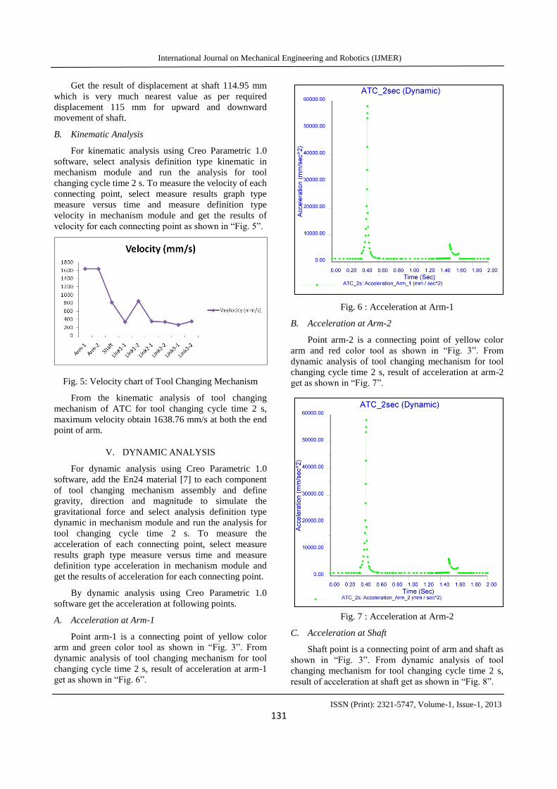
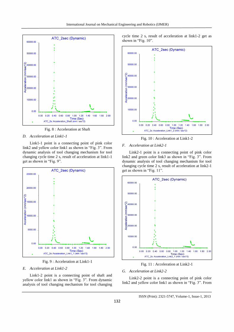
ISSN (Print): 2321-5747, Volume-1, Issue-1, 2013 129 Design and Dynamic Analysis of an Automatic Tool Changing Mechanism used in VMC M. B. Vaghela, V. J. Savsani & S. B. Jadeja B. H. Gardi College of Engineering & Technology, Rajkot, Pandit Deendayal Petroleum University, Gandhinagar, E-mail : [email protected], [email protected], [email protected]Abstract - Design analysis of high speed automatic tool changing mechanism for high speed machines like VMC, and minimize tool changing cycle time as compare with current used ATC. To get the result of displacement, velocity, acceleration at every connecting point for tool changing cycle time 2s by using mechanism module in Creo Parametric 1.0 software. By dynamic analysis get the results for acceleration at every connecting point in tool changing mechanism. Main goal of this paper is find out total force applied at every connecting points with consider total mass of component and also consider relative force applied at point from getting acceleration result from the dynamic analysis of tool changing mechanism in Creo parametric 1.0 software. With getting this total applied force, do the FEA for critical component of tool changing mechanism and as per that result if possible than redesign the component ant try to reduce the tool changing cycle time. Keywords - ATC: Automatic Tool Changer, Creo Parametric 1.0, Dynacam 10, Dynamic Analysis, FEA: Finite Element Analysis, Motion Analysis, Tool Changing Mechanism, and VMC: Vertical Machining Centre. I. INTRODUCTION Today’s fast growing automatic manufacturing process; to develop high speed automatic machine is a very challenging task for that required to develop high speed tool changing mechanism with minimum tool changing cycle time for VMC type of machine. Tool changing mechanism of ATC for VMC type of machine having simultaneously two types of motion which is occurred at shaft, downward and upward motion and rotary motion of shaft. For downward and upward motion of shaft used radial cam and for rotary motion of shaft used globoidal cam. To design and analysis of radial cam used graph [8] of arm downward and upward movement versus cam rotation angle and for globoidal cam used graph [8] of arm rotating chart versus cam shaft rotation angle with the help of Dynacam 10 software [10]. To design and develop high speed tool changing mechanism, do the design and analysis of some critical components like radial cam, globoidal cam [1] and take existing design of shaft and linkage mechanism from the company [9] and also design the other components which is required for make a complete assembly of tool changing mechanism of ATC [1]-[2]. ATC with using Creo Parametric 1.0 software and to get the results of displacement by position analysis, velocity by kinematic analysis and acceleration by dynamic analysis for each defined connecting points with using mechanism module of Creo parametric 1.0 software. Compare result of displacement of shaft with actual required movement and from the result of dynamic analysis got the result for acceleration, with using acceleration result find the total applied force at each define connecting point. II. DESIGN AND ANALYSIS OF CAMS In tool changing mechanism of ATC two motions which is occurred at shaft, downward and upward motion of shaft and rotary motion of shaft. For downward and upward motion of shaft used radial cam and for rotary motion of shaft used globoidal cam. A. Design and Analysis of Radial Cam To design and analysis of radial cam used Dynacam 10 software [10] and graph of arm downward and upward movement versus cam rotation angle[8].Radial cam design for maximum displacement 115 mm. From Dynacam 10 software getting results of displacement, velocity, acceleration and jerk for each degree 0° to 360° and also get cam profile of radial cam. Based on
Transcript
ISSN (Print): 2321-5747, Volume-1, Issue-1, 2013
129
Design and Dynamic Analysis of an Automatic
Tool Changing Mechanism used in VMC
M. B. Vaghela, V. J. Savsani & S. B. Jadeja
B. H. Gardi College of Engineering & Technology, Rajkot,