This paper presents an implementation of real-time energy management systems (EMS) to maximize the efficiency of the electricitydistribution in an isolated hybrid microgrid system (HMGS) containing photovoltaic modules, wind turbine, battery energy storagesystem, and diesel generator (DG) which is used as a backup source. These systems are making progress worldwide thanks to theirrespect for the environment. However, hybridization of several sources requires power flow control (PFC). For this reason, in thiswork, a proper energy management system is developed using LabVIEW software and embedded in a suitable platform for the real-time management of the hybrid energy system. The developed EMS is tested and validated through a small-scale application whichaccurately represents the case study of an isolated mosque located in a remote area of Morocco. The aim of this paper is to (i)propose a novel modelling method and real-time monitoring interface under the LabVIEW software based on the real dataobtained by an optimal sizing previously made using Homer-pro software and (ii) implement the power control system on alow-consumption embedded platform that is the Raspberry-pi3.
1. Introduction
Access to energy is now considered as a central issue in thefight against poverty and economic development. The pro-portion of the world’s population with access to electricityhas gradually increased in recent years. However, despitethese improvements, 1.1 billion people are still deprived ofthis essential service, with the majority of these peoplelocated in Africa. Among those who have gained access toelectricity in the world since 2010, only 20% live in ruralareas [1]. In Morocco, almost 1.3 million rural people aredeprived of electricity; i.e., 88902 households do not haveaccess to electricity [2]. Most of these rural homes arelocated in isolated or hard-to-access locations and do notallow connection to an electrical grid since the investmentcost is very large and online losses become significant. Itis then necessary to be able to install the infrastructuresfor electrification in sparsely populated areas and awayfrom the main grid.
In recent years, rural electrification has been achievedwith DG or with stand-alone renewable energy sources,including photovoltaics and wind power, which have beenconsidered promising to meet the growing demand forenergy and play a very important role in the clean energyproduction. However, renewable energy depends to a largeextent on wind speed or solar radiation. In order to providea continuous supply by taking advantage of the complemen-tary nature of the two sources of energy, one solution is tohybridize the types of sources in the form of the microgrid.
HMS were considered attractive and preferred alterna-tives; indeed, the development of microgrid in rural areasmakes it possible to electrify villages located far from the dis-tribution grid with renewable energy sources (RES) in a moresustainable way. Another major factor in the development ofmicrogrid systems is the sharp drop in the cost of renewableenergies, which makes these energies competitive withtraditional fossil fuels. Similarly, energy storage solutionsare currently undergoing significant development due to
HindawiInternational Journal of PhotoenergyVolume 2019, Article ID 8974370, 16 pageshttps://doi.org/10.1155/2019/8974370
the improvement of different technologies and lower pro-duction costs. In addition to renewable energy sources, aHMGS may also incorporate an AC distribution system, aDC system, a storage system, power converters, loads, a bal-last load, and an EMS or a supervisory system. In most cases,HMGS contain two buses: a DC bus for sources, DC loads,and batteries and an AC bus for AC generators and thedistribution system.
The technoeconomic analysis of any hybrid renewableenergy system (HRES) is highly essential to know its effi-ciency and economic viability, so several methods for optimalsizing have been proposed in the literature [3–11]. Theseworks across the world have shown that a HRES is more eco-nomical than stand-alone energy systems. However, theintermittent nature of renewable energy sources requiresproper power management in order to improve overall per-formance and increase the lifespan of the microgrid compo-nents. Therefore, adequate management of the energy flowthrough the HRES and the establishment of a supervisorysystem are essential.
Various control strategies and topologies for an autono-mous hybrid system have been reported in the literature[12–17]. Mengi and Altas have proposed a new energymanagement technique for PV/wind/grid renewable energysystem in [18]; likewise, an evaluation of three EMSs wascarried out by [19] to identify the most effective one. In addi-tion, [20] proposed four optimization techniques for resolv-ing an economic dispatch problem; the application is madeon the system connected and not connected to the grid.[21] seeks to develop a dynamic energy management modelfor microgrid-enabled production systems. [22, 23] proposedmanagement architectures multiagent based with bothcentralized and decentralized energy. [24] developed a coor-dinated control strategy for a stand-alone hybrid system withthe aim of maintaining the battery state between 70% and80% and maintaining the DG power above 40% of its nomi-nal value. Likewise, a fuzzy logic technique is used to formu-late a rebel control system for a HMGS [25–27]. Otherresearchers create new management strategies to minimizethe total and operating cost of stand-alone hybrid energy sys-tems [28, 29]. A control strategy consisting of the high-passfilter-based droop controller is realized by [30]. [31] cameup with a mathematical formulation of the energy manage-ment problem and its implementation in a centralized EMSfor isolated microgrid. For the grid connected microgrid sys-tems, the energy management aims at reducing the depen-dence on the main distribution grid in the microgrid [32–35].
On the other hand, researchers proposed a microgridpower management system (PMS) in real time [36–38]. Anadvanced real-time EMS for a microgrid is developed tomaximize the power of the available RES while minimizingthe energy cost and carbon dioxide emissions [39]; also, amultiobjective power management procedure for microgridis carried out by [36]. [40] developed a technical and eco-nomic analysis of home EMS incorporating a small-scalewind turbine and battery energy storage system; the EMSis expressed as a mixed integer nonlinear programming(MINLP) and solved by the cultural algorithm as an effectivemetaheuristic optimization algorithm.
A new field of research has appeared in recent years thathas focused on the management of domestic energy [41, 42].Novel home EMS using wireless communication technologiesfor carbon emission reduction within a smart-grid smoothpower peak demand and diminish CO2 emissions is carriedout by [43]. In the same way, three approaches are suggestedfor the rolling optimization by the home EMS, namely, mixedinteger linear programming, continuous relaxation, and fuzzylogic controller [44]. ZigBee-based energy measurementmodules are used to monitor the energy consumption ofhome appliances and lights [45]. Likewise, [46] developed adistributed multicontrol-center dynamic power flow algo-rithm based on an asynchronous iteration scheme.
Most of the articles cited above regarding power manage-ment are simulation work and theoretical formulation; fewarticles present a practical implementation. Experimentalevaluation of a PMS for a HRES with hydrogen productionpresents a PMS based on a fuzzy control system takes intoaccount the uncertainties of the load demand and the powerproduction from renewable energy sources for a HRES [47].In an EMS implementation in Serbian manufacturing, thePlan-Do-Check-Act cycle approach with the aim to cutenergy consumption and CO2 emissions is proposed by[48]. [49] present the energy box concept in the context ofthe V2G (vehicle-to-grid) technology to address the energymanagement needs of a modern residence, considering thatthe available infrastructure includes microrenewable energysources in the form of solar and wind power. A real-time loadmanagement is developed to control unpredictable residen-tial loads [50]; the developed control is implemented on anARM Cortex-A9 processor of the ZYNQ device. Likewise, asupervisory PMS for a hybrid microgrid with HESS is pre-sented by [51].
In this article, we consider the case study of a mosquelocated in a mountain area of Morocco. First, we performan optimal sizing to identify the best combination of energysources. Then, we perform a design and modelling usingthe LabVIEW software. Finally, we carry out an experimentalevaluation of the PMS on a real-time platform that is theRaspberry-pi 3 equipped with a microprocessor ARMv8,1.2GHz 64-bit quad-core.
The aim of this work is to realize an optimal configura-tion of a hybrid PV-wind-diesel; a supervision system withthe function of ensuring a secure, reliable, and efficient oper-ation of the microgrid; and the implementation of a real-timePMS to verify the effect of the RES variation on the evolutionof the system.
The contributions of this article are
(i) feasibility study of a HMGS based on PV, wind tur-bine, and diesel generator using the actual solar radi-ation and the wind speed data to power a mosquelocated on an isolated site in Morocco
(ii) modeling of the microgrid and the creation of asupervision dashboard to monitor the evolution ofthe system under the LabVIEW software
(iii) implementation of the PMS on an embedded RPI3platform
2 International Journal of Photoenergy
2. Studied System
The energy system studied in this paper is a stand-alonehybrid system that contains RES (PV panels and a windturbine) associated with a standby diesel generator andstorage battery. The structure of this AC/DC microgrid isshown in Figure 1. The PV and the battery are connected tothe DC bus and the wind turbine; the GD and the loads areconnected to the AC bus on the other side.
3. Sizing of the HMGS
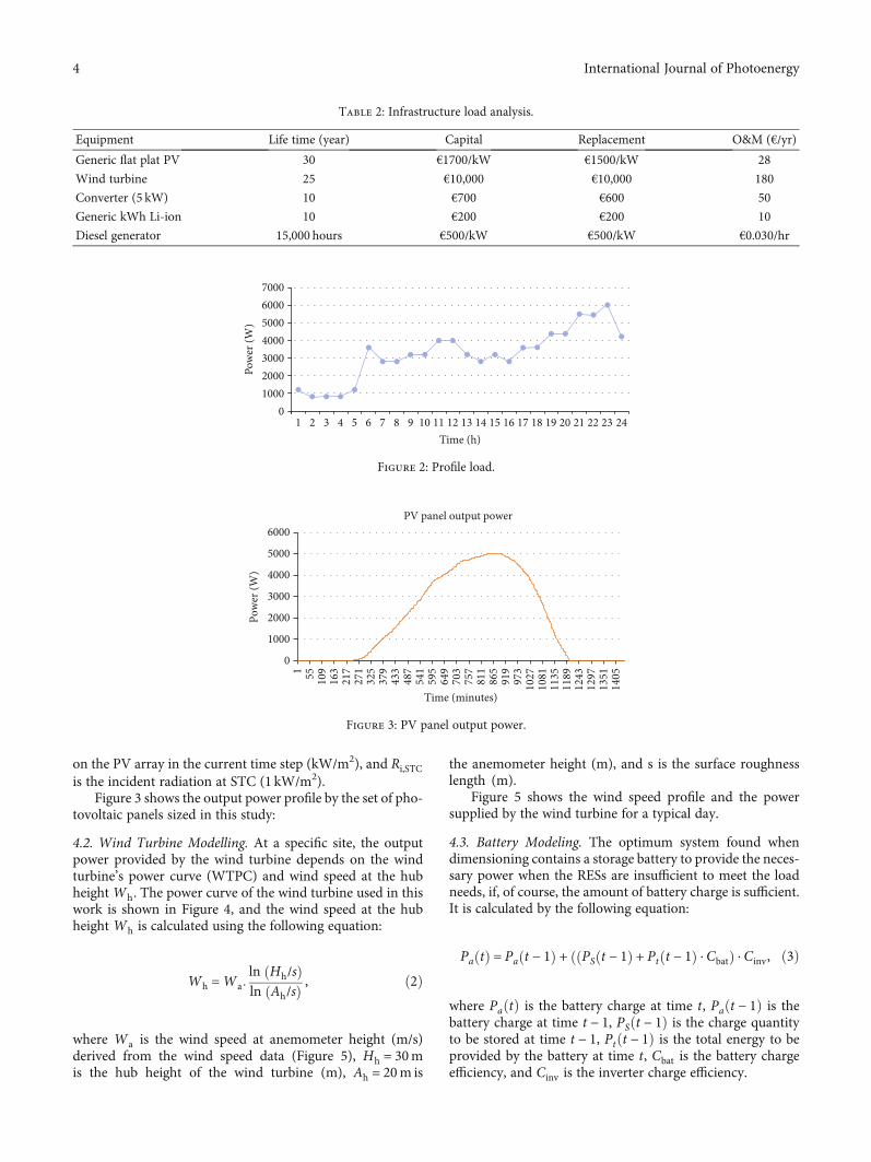
In this study, we chose an isolated load under real operatingconditions. It is a mosque located in the center of Morocco(33°45′11″N latitude; 04°30′57″W longitude), with a dailyload of 77 kWh/day; the detail of the consumption and thedescription of the major economic input data used in themodel to define the optimal size of the different componentof the hybrid energy system are given in Table 1 andTable 2, respectively.
The daily profile of the load is shown in Figure 2. In thiswork, the load is modelled by its demand per power hour.
In order to supply this load, it is necessary to identify theoptimum system between the various possible combinations(diesel only, PV-diesel, wind-diesel, and PV-wind-diesel).For this reason, a sizing of the hybrid system was carriedout with HOMER-Pro software, for a 25-year project life-time, using actual solar radiation data, wind speed, and eco-nomic data of the various components.
4. Modelling of the Proposed System
4.1. Photovoltaic Module. The photovoltaic output powerdepends on the incident solar radiation, and the hourly out-put power of the PV panel at any time t is calculated using thefollowing equation:
PPV = PPV,STCDf ,PVRi
Ri,STC
� �, ð1Þ
where PPV,STCis the power provided by the PV array understandard test conditions (STC) (kW), Df ,PV is the numberof the derating factor (%), Ri is the solar radiation incident
Wind turbine (3 kW)
DC busAC bus
Generator
Bidirectionconverter (5 kW)
PV array
AC
DCGeneric Li-ion
(1 kWh)
Electric load (mosque)
Figure 1: Studied hybrid PV-wind-diesel system.
Table 1: Infrastructure load analysis.
Load description Quantity Power (watt) On-time (hr/day) Watt-hr/day
Outside lighting 2 125 11 2750
Garden lighting 3 80 11 2640
Inside lighting 40 100 6–8 24000–32000
Air conditioner 4 1200 6–8 28800–38400
Imam house — — — 3276–5868
Total 73268–81650
3International Journal of Photoenergy
on the PV array in the current time step (kW/m2), and Ri,STCis the incident radiation at STC (1 kW/m2).
Figure 3 shows the output power profile by the set of pho-tovoltaic panels sized in this study:
4.2. Wind Turbine Modelling. At a specific site, the outputpower provided by the wind turbine depends on the windturbine’s power curve (WTPC) and wind speed at the hubheightWh. The power curve of the wind turbine used in thiswork is shown in Figure 4, and the wind speed at the hubheight Wh is calculated using the following equation:
Wh =Wa:ln Hh/sð Þln Ah/sð Þ , ð2Þ
where Wa is the wind speed at anemometer height (m/s)derived from the wind speed data (Figure 5), Hh = 30mis the hub height of the wind turbine (m), Ah = 20m is
the anemometer height (m), and s is the surface roughnesslength (m).
Figure 5 shows the wind speed profile and the powersupplied by the wind turbine for a typical day.
4.3. Battery Modeling. The optimum system found whendimensioning contains a storage battery to provide the neces-sary power when the RESs are insufficient to meet the loadneeds, if, of course, the amount of battery charge is sufficient.It is calculated by the following equation:
Pa tð Þ = Pa t − 1ð Þ + PS t − 1ð Þ + Pt t − 1ð Þ ⋅ Cbatð Þð ⋅ Cinv, ð3Þ
where PaðtÞ is the battery charge at time t, Paðt − 1Þ is thebattery charge at time t − 1, PSðt − 1Þ is the charge quantityto be stored at time t − 1, Ptðt − 1Þ is the total energy to beprovided by the battery at time t, Cbat is the battery chargeefficiency, and Cinv is the inverter charge efficiency.
Table 2: Infrastructure load analysis.
Equipment Life time (year) Capital Replacement O&M (€/yr)
State of charge (SOC) of the battery depends on the loadrequirement and the power provided by the RES, and it iscalculated using the following equations:
(i) For the charging mode,
SOC tð Þ = SOC t − 1ð Þ + Pbat tð ÞCchar
PN⋅ 1 ð4Þ
(ii) For the discharging mode,
SOC tð Þ = SOC t − 1ð Þ + Pbat tð ÞCdis
PN⋅ 100, ð5Þ
where SOCðtÞ is the state of charge of the battery at time t,PbatðtÞis power exchange during the time step Δt, Cchar isthe battery charge efficiency, Cdis is the battery dischargeefficiency, and PN is the battery nominal capacity.
4.4. Diesel Generator Modeling. The diesel generator used inthis study is of the genset type with a maximum power of10 kW; its function is to deliver the power difference betweenthe power generated by the RES and the load profile when the
battery is discharged; it always works near its rated power,to increase its lifetime and to minimize emissions andconsumption. This consumption is given by the followingequation:
Fc tð Þ = α × Pnom + β × Pout, ð6Þ
where α and β are the coefficients of the straight linepresented in Figure 6. Pout and Pnom are the output powerand the nominal power of the DG, respectively.
5. Energy Management System
5.1. Proposed Energy Management Scheme Based on PowerFlow Control. Energy management in a microgrid is theway to distribute energy between different components andto meet the load requirement in all climatic conditions. Inthis paper, the microgrid is insulated and consists of severalpower sources; the control systemmust ensure the maximumsupply of the load by the RES (wind turbine, PV).
The diagram of the EMS proposed in this article is shownin Figure 7. It allows to control the energy flow between thedifferent components and to display the indicators for theuser. The main tasks of the control system can be summa-rized as follows:
(b) Avoid interruptions of electrical power supply
(c) Protect batteries from deep discharge andoverload
(d) Automatic start and stop of the diesel generator
(e) Connect and disconnect the ballast load auto-matically in the event of excess energy generatedby the RES
(ii) Supervision
(a) Inform the user if the power generated by the PVand the wind turbine is sufficient or not
(b) Inform the user if power is supplied to the loadand by which energy system
(c) Indicate whether the DG is running or stopped
(d) Display the SOC of the battery and indicatewhether it is plugged in or not
(e) Indicate if ballast load is connected or not
5.2. Power Management Algorithm. The purpose of PMS is toensure the supply of the load. To meet the specificationsdefined in the previous section the proposed algorithm isshown in Figure 8. It is based on 5 modes:
(i) PV mode (PL < PPV): the power supplied by the PVsis sufficient to supply the load. This mode is thehighest priority in our case, if it is activated, thepower produced by the PV panels is greater thanthe requested power by the load; in this case, the loadis powered by the PVs and the wind turbine is dis-connected if the battery is charged (SOC; SOCmax)or charging the battery if SOC < SOCmax
(ii) Wind mode (PPV < PL and PL < PW): the powerprovided by the wind turbine is sufficient for the
00.5
11.5
22.5
33.5
4
0 2 4 6 8 10Fu
el co
nsum
ptio
n (L
/hr)
Output power (kW)
Figure 6: Power curve of DG.
Profile load
Wind output power
PV panel output power
Battery state of charge
SOCEnergy management system
Battery
Ballast load
Diesel generator
PV panels
Wind turbine
Supervision
Supervision interface
Load
Figure 7: General structure of the proposed system.
6 International Journal of Photoenergy
power supply. This mode is activated if the powerprovided by the PVs is not sufficient. The load isfed by the wind turbine. The PVs load the battery ifSOC < SOCmax and they are disconnected otherwise
(iii) PV/wind hybrid mode (PPV < PL and PL < PW andPPV + PW > PL): the load is fed by the two RESs(wind and PV). This mode is on if the first twomodes are not activated. In this case, the battery ischarged by the remaining power if SOC < SOCmax.Otherwise, the rest of power feeds a ballast load
(iv) PV/wind/battery hybrid mode (PPV < PL and PL <PW and PPV + PW < PL and SOCmin < SOC ≤ SOCmax): in this case, the RESs are not able to ensurethe requirement of the load; the battery ensures thelack of power
(v) PV/wind/diesel hybrid mode (PPV < PL and PL < PWand PPV + PW < PL and SOC ≤ SOCmin): the loadcannot be fed by the two RESs (wind and PV) andthe battery is discharged. This mode is activated if
the preceding modes are not activated; in this mode,the DG is started to complete the lack of energy
5.3. LabVIEW Code for Controlling the Power Flow of theMicrogrid. Simulation step must be performed prior toimplementation. In this study, the operation of the HMGSis tested using the LabVIEW software, for a typical day.Figure 9 shows the power management program, consistingof 3 parts:
(i) System inputs: the load profile (Figure 2), the powergenerated by the PVs (Figure 3), the power suppliedby the wind turbine (Figure 5), and the SOC of thebattery for each one-minute time space
(ii) Controller: corresponds to the operation defined bythe algorithm shown in Figure 8
(iii) System outputs: corresponds to the actuators and todisplays that indicate the status of each source andload (dashboard).
0 < t <1440
PL ≤ PPV
SOC < SOCmax
SOCmim < SOCmim
SOC = SOCmax
PL ≤ PWT
PL = PPV+ PWT
SOC < SOCmax
PL = PPV+ PWT
Start
End
PL, PPV, PWT, SOC
Feed the loadGD disconnectedBL disconnectedBattery charging from WT
Feed the loadGD disconnectedBL disconnectedBattery charging from PVpanels
Feed the loadGD disconnectedBL connectedBattery disconnected
Feed the loadGD disconnectedBL disconnectedPV panels disconnectedBattery disconnected
Feed the loadGD disconnectedBL disconnectedWT stoppedBattery disconnected
Feed the loadGD disconnectedBL disconnectedBattery charging
Battery chargingFeed the loadGD connectedBL disconnectedBattery disconnected
Feed the load GD disconnectedBL disconnectedBattery discharging
Yes
No
No
No
No
No
No
No
No
Yes Yes
Yes Yes
YesFeed the loadGD disconnectedBL disconnectedBattery disconnected
YesYes
Yes
No
PV mode
Wind mode
PV/wind hybrid mode
PV/wind/battery hybrid mode
PV/wind/diesel hybrid mode
Figure 8: Proposed power management algorithm.
7International Journal of Photoenergy
6. Hardware Implementation
After sizing a HRES to justify the choice of the PV-wind-diesel system, we developed a management algorithm andwe carried out a successful simulation on LabVIEW, using
real radiation and wind speed data. The simulations showthe feasibility of such a system.
In this section, we implement the energy control systemon an embedded platform such as the Raspberry-pi 3.Figure 10 shows the overall electrical scheme. Power sources
Drums
Home
Insufficient solar energy
Insufficient wind energyaddition of 6 sources
6
Ignition of emergency generatorin short
On
True
False
False
False
False Solar display
Wind display
Wind-PV display
Diesel generator
Diesel generator
24
Charge requiring asummation of
source
True
False
12
Load controller display
10
Slide
%2f
%2f
%2f
Table 2
Table 1
0
1
2
Solar
Load profile
Wind turbine
Generator
Tab control
1443
False
False
60
False
80
Ballast load.
0
0
Table 2
00
Figure 9: LabVIEW code for controlling the power flow of the microgrid.
ArduinoRaspberry-pi
Diesel generator
Wind turbine
PV panels
Battery
Electrical relays Load
Load control
Figure 10: General scheme of the hardware implementation.
8 International Journal of Photoenergy
and load are connected to the Raspberry-pi through an Ardu-ino. Part of the Raspberry pins will control the relays, whichare wired directly to the sources, and other pins will controlthe different loads.
6.1. Raspberry-Pi. Raspberry-pi 3 (RPI3) is an open hardwareplatform and is a low-cost ARM-based palm-size computer,featuring a quad-core 1.2GHz processor, 1GB of RAMmemory, 4 USB, 10/100 Ethernet, GPIO, HDMI and com-posite video outputs, and SD card slot. RPI is small in sizeand it consumes 5V electricity at 1A current due to whichpower consumption of the Raspberry-pi is less.
It allows the execution of several variants of the freeGNU/Linux operating system and compatible software. Wechose the Raspbian distribution Linux embedded operatingsystem. The programming is done using the Python languagewish is a structured and object-oriented programminglanguage. It features dynamic typing, automatic memorymanagement, and an exception management system.
6.2. Relays. The relay circuit was designed to be able to switchthe different sources, according to the program executed bythe Raspberry, which translates the proposed algorithm. For
the realization of this one, we used ISIS software as shownin Figure 11.
Four coils of the relay are powered by 5V pin of the Rpiand the masses are isolated by transistors 2N2222. Each relaycorresponds to a power source and the control is sent by theRpi. A current passes to the base of the transistor, then thecoil of the relay is energized; this will make it possible touse the energy of the chosen source.
After verifying the operation of the circuit on ISIS, werealized the printed circuit using ARES software. Thus, wehave obtained the printed circuit indicated in Figure 12.
6.3. Load Control Circuit. To test the management programpractically, we took lamps as the system load and a fan asthe ballast load. The control circuit that controls thesecharges is realized. Figure 13 shows its diagram on ISIS andFigure 14 shows its implementation on ARES.
6.4. Arduino. It is a circuit whose main constitution is amicrocontroller that can be programmed to perform verydifferent tasks. Its programming is done using the Arduinointegrated development environment, which is a free andcross-platform Java Application, which can be used as a codeeditor and a compiler, and which can transfer the firmware
RL1G5CLE-1-DC12
RL2G5CLE-1-DC12
RL3G5CLE-1-DC12
RL4G5CLE-1-DC12
Q12N2222
Q22N2222
Q32N2222
Q42N2222
J8
PIN
J9
PIN
J10
PINJ11
PINJ12
PIN
J7
PIN
J6
PIN
J5
PIN
J4
PIN
J3
PIN
J2
PIN
J1
PIN
J13PIN
J14PIN
J15PIN
J16PIN
Figure 11: ISIS diagram of the relay circuit.
9International Journal of Photoenergy
and the program via the serial link (RS-232, Bluetooth, orUSB depending on the module).
In our case, the power management program has beenimplemented on the Raspberry; however, the Rpi does notcontain any analog inputs, so we used the Arduino to convertthe analog data received from the power sources to digitalvalues. As a result, two programs will be developed, one for
the Raspberry (for management) and one for the Arduinoto do the data transfer.
7. Results and Discussion
7.1. Sizing Results. Figure 15 shows the comparison of allpossible combinations from an economic and ecological
J6
J5
J16J1
Q1
Q2
Q3
Q4
J2
J3
J4
J15
J14
J13
RL1
RL2
RL3
RL4
J7
J9
J5
J8
J10
J12
Figure 12: ARES diagram of the relay circuit.
Q12N2222
Q22N2222
Q32N2222
Q42N2222
Q52N2222
Q6Q7
2N2222
Q8
2N2222
Q9
2N2222
Q10
2N2222
D1DIODE
D2DIODE
D3DIODE
D4DIODE
D5DIODE
R110k
R210k
R310k
R410k
R510k
R610k
R710k
R810k
R910k
R1010k
R1110k
R1210k
R1310k
R1410k
R1510k
R1610k
D6DIODE
D7DIODE
D8DIODE
D9DIODE
D10DIODE
2N2222
Figure 13: ISIS diagram of the load control circuit.
10 International Journal of Photoenergy
point of view (net present cost and the amount of green-house gas emissions). This figure shows the interest ofusing HMGS compared to the current situation of the die-sel generator. Hybrid PV-wind-diesel system (PWDS) pro-duces better results compared to the PV-diesel system(PDS), wind-diesel system (WDS), and diesel-only system(DS).
The sizing result using the Homer-pro software showsthat the optimal system is a hybrid system based on 5 kWpanels, the wind turbine of 3 kWp, and a genset of 10 kWbackup diesel generator, combined with a generic kWh stor-age battery Li-ion 1 kWh and a Leon s219cph 5 kW 48Vdcbidirectional converter (BDI 1P).
Further information on the system inputs and otherresults of this dimensioning can be found in [52].
7.2. Modelling Results. In order to test and monitor microgridperformance under real conditions, a simulation study isdone using LabVIEW software. The simulation results con-sist mainly of 2 components: the user interface realized inthe form of a dashboard that allows the user to see the stateof the microgrid every minute. As shown in Figure 16, it iscomposed of
(i) two tables: Table 1 contains the actual values of theload as well as the powers of the renewable energy
R1
D1
R2
Q1
Q6
Q7
Q8
Q9
Q10
R10
D6
D7
D8
D9
D10
R9R12
R11
R14
R13
R8R7R16
R15
Q2
Q3
Q4
Q5
R3R4R5R6
D2
D3
D4
D5
Figure 14: ARES diagram of the load control circuit.
010002000300040005000600070008000900010000
0.0
10,000.00
20,000.00
30,000.00
40,000.000
50, 000.00
60, 000.00
70,000.00
PV-wind-diesel Wind‑diesel PV‑diesel Diesel
Emiss
ions
(kg/
yr)
NPC
(€)
NPC (€)Emissions (kg/yr)
Figure 15: NPC and amount of emissions of each combination.
11International Journal of Photoenergy
and Table 2 displays the results of the simulatedvalues and their execution times as well as the date
(ii) 4 LEDs indicate whether the load is powered or not,the battery is connected or not, the DG is on or off,and the ballast load is feed or not
(iii) the SOC level of the battery
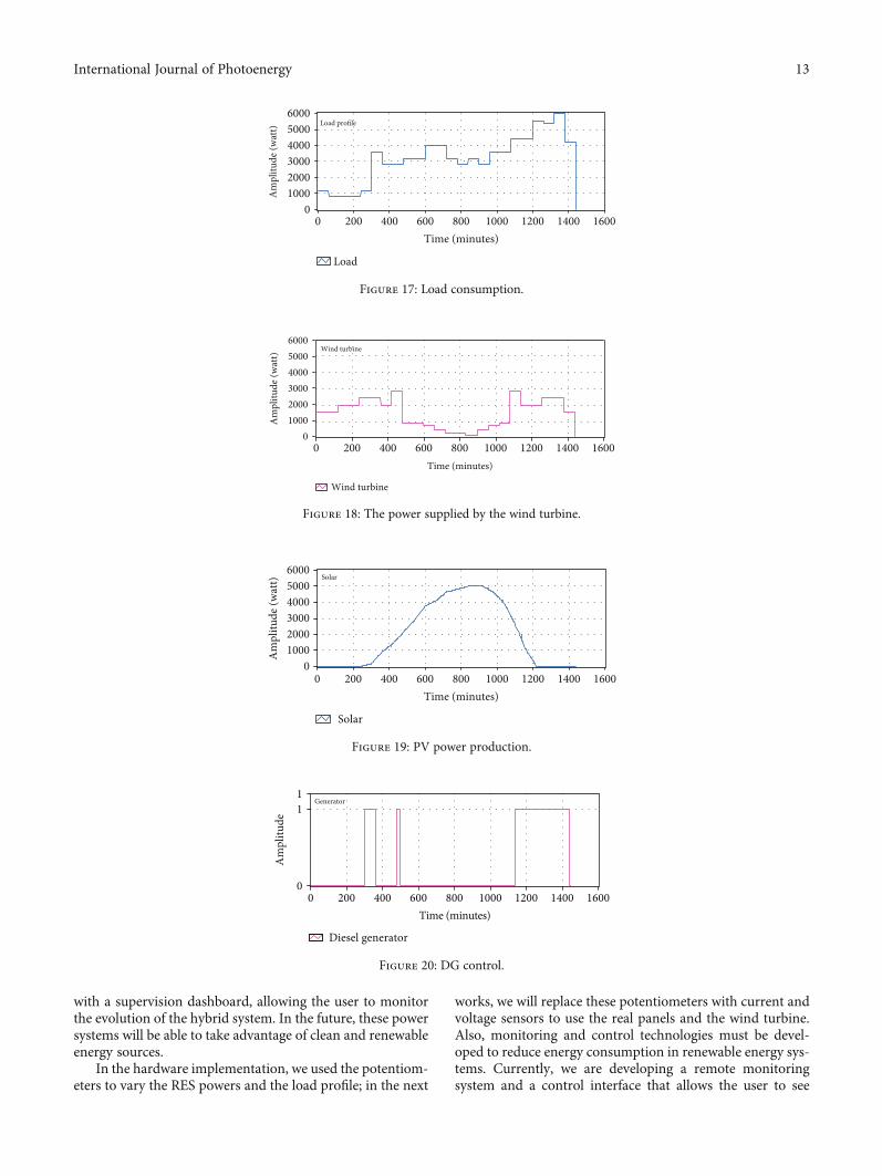
(iv) 5 displays showing the status of each energy sourceand the need for the load during the execution ofthe program; the user can see the evolution curvesof powers in real time. We used memory oscillatorsto get the results for 24 h
Figure 17 shows the power supplied by the various energysources. As can be seen, it corresponds to the required loadprofile. Figures 18 and 19 represent the power evolution pro-vided by the wind turbine and the PV panels, respectively.
Figure 20 shows the state of the diesel generator; it isstarted 3 times during the day.
7.3. Experimental Result. Figure 21 shows the first setup ofour microgrid; it is a model realized with modest personalmeans. We have used potentiometers to vary the powers pro-vided by energy sources on purpose to visualize the effect of
this variation in real time. Similarly, for the load, we took 5lamps and a fan as the ballast load.
Arduino receives the power values provided by thepower sources and the battery (potentiometers); it handlesthe analogue digital conversion and then transfers them tothe RPI3, which executes the power management program,and reacts to the loads according to the flow chart ofFigure 8.
8. Conclusion and Future Work
This paper presents an implementation of real-time energymanagement systems (EMS) to maximize the efficiency ofthe electricity distribution in a microgrid. The grid serves aload with an off-grid hybrid renewable energy system madeof photovoltaic modules, a battery energy storage system, adiesel generator, and a wind turbine. Furthermore, a properpower flow control is developed using LabVIEW softwareand embedded in a suitable platform for the real-time man-agement of the hybrid energy system. The developed EMSis tested and validated through a small-scale applicationwhich accurately represents the case study of an isolatedmosque located in a remote area of Morocco.
This system can be introduced into a microgrid to mon-itor its components. The system is realized and is equipped
Off
Diesel generator
Solar charging batteryWind-PV display
Sufficient wind powerWind display
Insufficient solar energySolar display
Very large load requiring theLoad controller display
Figure 16: LabVIEW user interface of the microgrid.
12 International Journal of Photoenergy
with a supervision dashboard, allowing the user to monitorthe evolution of the hybrid system. In the future, these powersystems will be able to take advantage of clean and renewableenergy sources.
In the hardware implementation, we used the potentiom-eters to vary the RES powers and the load profile; in the next
works, we will replace these potentiometers with current andvoltage sensors to use the real panels and the wind turbine.Also, monitoring and control technologies must be devel-oped to reduce energy consumption in renewable energy sys-tems. Currently, we are developing a remote monitoringsystem and a control interface that allows the user to see
00
200 400 600 800Time (minutes)
Load
600050004000300020001000A
mpl
itude
(wat
t)
1000 1200 1400 1600
Load profile
Figure 17: Load consumption.
600050004000300020001000A
mpl
itude
(wat
t)
0
Wind turbine
Wind turbine
Time (minutes)
0 200 400 600 800 1000 1200 1400 1600
Figure 18: The power supplied by the wind turbine.
0 200 400 600 800Time (minutes)
1000 1200 1400 1600
Solar
Solar
600050004000300020001000A
mpl
itude
(wat
t)
0
Figure 19: PV power production.
1
0
1
Time (minutes)16000 200 400 600 800 1000 1200 1400
Diesel generator
Generator
Am
plitu
de
Figure 20: DG control.
13International Journal of Photoenergy
the power variations and the state of the battery, thus con-trolling remote power sources. For this reason, we created ahosting server as well as its configuration; thus, we installedthe PHP language and a web server named APACHE inorder to communicate with the RPI3 using its IP addressand to control it from afar.
Data Availability
The data used to support the findings of this study have notbeen made available because they are confidential.
Conflicts of Interest
The authors declare that there is no conflict of interestregarding the publication of this paper.
References
[1] United Nations Department of Economic and Social Affairs,Rapport sur les Objectifs de Développement Durable 2016,UN, 2018.
[2] R. Maroc, Projet de Loi de Finances pour l’année budgétaire2017, MINISTÈRE DE L’ÉCONOMIE ET DES FINANCES,Morocco, 2017.
[3] S. A. Shezan, S. Julai, M. A. Kibria et al., “Performance analysisof an off-grid wind-PV (photovoltaic)-diesel-battery hybridenergy system feasible for remote areas,” Journal of CleanerProduction, vol. 125, pp. 121–132, 2016.
[4] S. Goel and R. Sharma, “Performance evaluation of standalone, grid connected and hybrid renewable energy systemsfor rural application: a comparative review,” Renewable andSustainable Energy Reviews, vol. 78, pp. 1378–1389, 2017.
[5] Y. Sawle, S. C. Gupta, and A. K. Bohre, “Review of hybridrenewable energy systems with comparative analysis of off-grid hybrid system,” Renewable and Sustainable EnergyReviews, vol. 81, pp. 2217–2235, 2018.
[6] J. Jung and M. Villaran, “Optimal planning and design ofhybrid renewable energy systems for microgrids,” Renewableand Sustainable Energy Reviews, vol. 75, pp. 180–191, 2017.
[7] M. D. A. Al-falahi, S. D. G. Jayasinghe, and H. Enshaei, “Areview on recent size optimization methodologies for standa-lone solar and wind hybrid renewable energy system,” EnergyConversion and Management, vol. 143, pp. 252–274, 2017.
[8] M. Boussetta, R. El Bachtiri, M. Khanfara, andK. El Hammoumi,“Assessing the potential of hybrid PV-Wind systems to coverpublic facilities loads under different Moroccan climate con-ditions,” Sustainable Energy Technologies and Assessments,vol. 22, pp. 74–82, 2017.
[9] N. Izadyar, H. C. Ong, W. T. Chong, J. C. Mojumder, and K. Y.Leong, “Investigation of potential hybrid renewable energy atvarious rural areas inMalaysia,” Journal of Cleaner Production,vol. 139, pp. 61–73, 2016.
[10] D. Saheb-Koussa, M. Haddadi, and M. Belhamel, “Economicand technical study of a hybrid system (wind-photovoltaic-diesel) for rural electrification in Algeria,” Applied Energy,vol. 86, no. 7–8, pp. 1024–1030, 2009.
[11] R. Accorsi, M. Bortolini, M. Gamberi, R. Manzini, and F. Pilati,“Multi-objective warehouse building design to optimize thecycle time, total cost, and carbon footprint,” InternationalJournal of Advanced Manufacturing Technology, vol. 92,no. 1–4, pp. 839–854, 2017.
[12] M. Gianni and K. Gotzamani, “Management systems integra-tion: lessons from an abandonment case,” Journal of CleanerProduction, vol. 86, pp. 265–276, 2015.
[13] L. Olatomiwa, S. Mekhilef, M. S. Ismail, and M. Moghavvemi,“Energy management strategies in hybrid renewable energysystems: a review,” Renewable and Sustainable Energy Reviews,vol. 62, pp. 821–835, 2016.
[14] A. A. Babayo, M. H. Anisi, and I. Ali, “A Review on energymanagement schemes in energy harvesting wireless sensornetworks,” Renewable and Sustainable Energy Reviews,vol. 76, pp. 1176–1184, 2017.
[15] A. M. Carreiro, H. M. Jorge, and C. H. Antunes, “Energy man-agement systems aggregators: a literature survey,” Renewable
Load control
Potentiometers
Implementation setup
Rpi3
Arduino
Relays
Fan Leds
Figure 21: Implementation setup.
14 International Journal of Photoenergy
and Sustainable Energy Reviews, vol. 73, pp. 1160–1172,2017.
[16] P. G. Arul, V. K. Ramachandaramurthy, and R. K. Rajkumar,“Control strategies for a hybrid renewable energy system: areview,” Renewable and Sustainable Energy Reviews, vol. 42,pp. 597–608, 2015.
[17] N. H. Mirjat, M. A. Uqaili, K. Harijan, G. D. Valasai, F. Shaikh,and M. Waris, “A review of energy and power planning andpolicies of Pakistan,” Renewable and Sustainable EnergyReviews, vol. 79, pp. 110–127, 2017.
[18] O. O. Mengi and I. H. Altas, “A new energy managementtechnique for PV/wind/grid renewable energy system,”International Journal of Photoenergy, vol. 2015, Article ID356930, 19 pages, 2015.
[19] S. Upadhyay and M. P. Sharma, “Selection of a suitable energymanagement strategy for a hybrid energy system in a remoterural area of India,” Energy, vol. 94, pp. 352–366, 2016.
[20] A. Maulik and D. Das, “Optimal operation of microgridusing four different optimization techniques,” SustainableEnergy Technologies and Assessments, vol. 21, pp. 100–120,2017.
[21] W. C. H. Schoonenberg and A. M. Farid, “A dynamic modelfor the energy management of microgrid-enabled productionsystems,” Journal of Cleaner Production, vol. 164, pp. 816–830, 2017.
[22] M. R. B. Khan, R. Jidin, and J. Pasupuleti, “Multi-agent baseddistributed control architecture for microgrid energy manage-ment and optimization,” Energy Conversion and Management,vol. 112, pp. 288–307, 2016.
[23] M. Mao, P. Jin, N. D. Hatziargyriou, and L. Chang, “Multia-gent-based hybrid energy management system for micro-grids,” IEEE Transactions on Sustainable Energy, vol. 5, no. 3,pp. 1–9, 2014.
[24] P. Taylor, C. K. Aravind, G. S. Ilango et al., “A control strategyfor hybrid autonomous power system with a battery man-agement scheme,” Electric Power Components and Systems,vol. 43, no. 8–10, pp. 37–41, 2015.
[25] F. Valencia, J. Collado, D. Sáez, and L. G. Marín, “Robustenergy management system for a microgrid based on a fuzzyprediction interval model,” IEEE Transactions on Smart Grid,vol. 7, no. 3, pp. 1486–1494, 2015.
[26] Z. Roumila, D. Rekioua, and T. Rekioua, “Energy manage-ment based fuzzy logic controller of hybrid system wind/-photovoltaic/diesel with storage battery,” InternationalJournal of Hydrogen Energy, vol. 42, no. 30, pp. 19525–19535, 2017.
[27] R. J. Wai, S. J. Jhung, J. J. Liaw, and Y. R. Chang, “Intelligentoptimal energy management system for hybrid power sourcesincluding fuel cell and battery,” IEEE Transactions on PowerElectronics, vol. 28, no. 7, pp. 3231–3244, 2013.
[28] P. García, J. P. Torreglosa, L. M. Fernández, F. Jurado,R. Langella, and A. Testa, “Energy management system basedon techno-economic optimization for microgrids,” ElectricPower Systems Research, vol. 131, pp. 49–59, 2016.
[29] C. Wang, Y. Liu, X. Li, L. Guo, L. Qiao, and H. Lu, “Energymanagement system for stand-alone diesel-wind-biomassmicrogrid with energy storage system,” Energy, vol. 97,pp. 90–104, 2016.
[30] Q. Xu, J. Xiao, X. Hu, P.Wang, andM. Y. Lee, “A decentralizedpower management strategy for hybrid energy storage systemwith autonomous bus voltage restoration and state-of-charge
recovery,” IEEE Transactions on Industrial Electronics,vol. 64, no. 9, pp. 7098–7108, 2017.
[31] D. E. Olivares, C. A. Cañizares, and M. Kazerani, “A central-ized energy management system for isolated microgrids,” IEEETransactions on Smart Grid, vol. 5, no. 4, pp. 1864–1875, 2014.
[32] S. H. C. Cherukuri and B. Saravanan, “A novel energy man-agement algorithm for reduction of main grid dependencein future smart grids using electric springs,” SustainableEnergy Technologies and Assessments, vol. 21, pp. 1–12,2017.
[33] Z. Yi, W. Dong, and A. H. Etemadi, “A unified control andpower management scheme for PV-battery-based hybridmicrogrids for both grid-connected and islanded modes,”IEEE Transactions on Smart Grid, vol. 9, no. 6, pp. 5975–5985, 2017.
[34] J. Zhang, L. Huang, J. Shu, H. Wang, and J. Ding, “Energymanagement of PV-diesel-battery hybrid power system forisland stand-alone micro-grid,” Energy Procedia, vol. 105,pp. 2201–2206, 2017.
[35] D. S. Koussa and M. Koussa, “A feasibility and cost benefitprospection of grid connected hybrid power system (wind-photovoltaic) - case study: an Algerian coastal site,” Renewableand Sustainable Energy Reviews, vol. 50, pp. 628–642, 2015.
[36] K. Dehghanpour and H. Nehrir, “Real-time multiobjectivemicrogrid power management using distributed optimizationin an agent-based bargaining framework,” IEEE Transactionson Smart Grid, vol. 9, no. 6, pp. 6318–6327, 2018.
[37] W. Shi, N. Li, C. Chu, and R. Gadh, “Real-time energy manage-ment in microgrids,” IEEE Transactions on Smart Grid, vol. 8,no. 1, pp. 1–11, 2015.
[38] A. Anvari-Moghaddam, J. M. Guerrero, J. C. Vasquez,H. Monsef, and A. Rahimi-Kian, “Efficient energy manage-ment for a grid-tied residential microgrid,” IET Generation,Transmission & Distribution, vol. 11, no. 11, pp. 2752–2761,2017.
[39] M. Elsied, A. Oukaour, T. Youssef, H. Gualous, andO. Mohammed, “An advanced real time energy managementsystem for microgrids,” Energy, vol. 114, pp. 742–752, 2016.
[40] R. Hemmati, “Technical and economic analysis of homeenergy management system incorporating small-scale windturbine and battery energy storage system,” Journal of CleanerProduction, vol. 159, pp. 106–118, 2017.
[41] A. M. Vega, F. Santamaria, and E. Rivas, “Modeling for homeelectric energy management: a review,” Renewable and Sus-tainable Energy Reviews, vol. 52, pp. 948–959, 2015.
[42] B. Zhou, W. Li, K. W. Chan et al., “Smart home energymanagement systems: concept, configurations, and schedulingstrategies,” Renewable and Sustainable Energy Reviews, vol. 61,pp. 30–40, 2016.
[43] H. Elkhorchani and K. Grayaa, “Novel home energy manage-ment system using wireless communication technologies forcarbon emission reduction within a smart grid,” Journal ofCleaner Production, vol. 135, pp. 950–962, 2016.
[44] Z. Wu, X. P. Zhang, J. Brandt, S. Y. Zhou, and L. I. Jia-Ning,“Three control approaches for optimized energy flow withhome energy management system,” IEEE Power and EnergyTechnology Systems Journal, vol. 2, pp. 21–31, 2015.
[45] J. Han, C. Choi, W. Park, I. Lee, and S. Kim, “Smarthome energy management system including renewable energybased on ZigBee and PLC,” IEEE Transactions on ConsumerElectronics, vol. 60, no. 2, pp. 198–202, 2014.
15International Journal of Photoenergy
[46] H. Zhang, B. Zhang, A. Bose, and H. Sun, “A distributedmulti-control-center dynamic power flow algorithm basedon asynchronous iteration scheme,” IEEE Transactions onPower Systems, vol. 33, no. 2, pp. 1716–1724, 2017.
[47] M. H. Cano, K. Agbossou, S. Kelouwani, and Y. Dubé, “Exper-imental evaluation of a power management system for ahybrid renewable energy system with hydrogen production,”Renewable Energy, vol. 113, pp. 1086–1098, 2017.
[48] B. Jovanović, J. Filipović, and V. Bakić, “Energy managementsystem implementation in Serbian manufacturing - plan-do-check-act cycle approach,” Journal of Cleaner Production,vol. 162, pp. 1144–1156, 2017.
[49] C. S. Ioakimidis, L. J. Oliveira, K. N. Genikomsakis, and P. I.Dallas, “Design, architecture and implementation of a residen-tial energy box management tool in a SmartGrid,” Energy,vol. 75, pp. 167–181, 2014.
[50] J. Khoury, R. Mbayed, G. Salloum, and E. Monmasson,“Design and implementation of a real time demand side man-agement under intermittent primary energy source conditionswith a PV-battery backup system,” Energy and Buildings,vol. 133, pp. 122–130, 2016.
[51] S. Kotra andM. K. Mishra, “A supervisory power managementsystem for a hybrid microgrid with HESS,” IEEE Transactionson Industrial Electronics, vol. 64, no. 5, pp. 3640–3649, 2017.
[52] M. Boussetta, R. Elbachtiri, M. Khanfara, andK. Elhammoumi, “Performance analysis and power evaluationof hybrid off-grid system,” inRenewable and Sustainable EnergyConference (IRSEC), International, Marrakech, Morocco, Nov.2016.
16 International Journal of Photoenergy
TribologyAdvances in
Hindawiwww.hindawi.com Volume 2018
Hindawiwww.hindawi.com Volume 2018
International Journal ofInternational Journal ofPhotoenergy
Hindawiwww.hindawi.com Volume 2018
Journal of
Chemistry
Hindawiwww.hindawi.com Volume 2018
Advances inPhysical Chemistry
Hindawiwww.hindawi.com
Analytical Methods in Chemistry
Journal of
Volume 2018
Bioinorganic Chemistry and ApplicationsHindawiwww.hindawi.com Volume 2018