Abstract—Flexure hinge has been commonly used as a substi-tute for mechanical joints in the design of micropositioning mecha-nisms. However, inaccurate modeling of flexure hinges deterioratesthe positioning accuracy. In this paper, a planar three-degree-of-freedom (DOF) parallel-type micropositioning mechanism is de-signed with the intention of accurate flexure hinge modeling. Forthis, a preliminary kinematic analysis that includes inverse kine-matics, internal kinematics, and analytic stiffness modeling refer-enced to the task coordinate is presented. First, the revolute typeof 1-DOF flexure hinge is considered. The simulation result basedon the finite element method, however, is not coincident to the ana-lytic result. This is due to the minor axial elongation along the linkdirection that keeps the mechanism from precise positioning. Tocope with this problem, a 2-DOF flexure hinge model that includesthis additional motion degree as a prismatic joint is employed inpart, and additional actuators are added to compensate for the mo-tion of this new model. On the basis of this model, the positionalaccuracy is ensured. The effectiveness of this accurate model isshown through both simulation and experimentation. This paperemphasizes that the precise modeling of a flexure hinge is signifi-cant to guarantee the positional accuracy of parallel micromecha-nisms using flexure hinge.
Index Terms—Flexure hinge, micromechanism, parallel mecha-nism, stiffness modeling.
I. INTRODUCTION
M ICROPOSITIONING mechanism is a key and essen-tial technology in many fields, such as scanning elec-
tron microscopy (SEM), X-ray lithography, mask alignment,and micromachining. Recently, there have been quite a numberof studies on the analysis and design of micropositioning mech-anisms with flexure hinges. Most of previous studies (Moriyamaet al. [1], Taniguchiet al. [2], Tomita et al. [3], Ryu et al. [4],Changet al. [5], Penget al. [6], [7]–[10]) modeled the flexurehinge by using only one degree of freedom (DOF) for a rev-olute hinge and only 3-DOF for a spherical hinge. However,the flexure hinge also has translational motion even though the
Manuscript received February 28, 2002; revised November 29, 2002. Thispaper was recommended for publication by Associate Editor M. Wang and Ed-itor I. Walker upon evaluation of the reviewers’ comments. This work was sup-ported in part by the Korea Health 21 R&D Project, Ministry of Health andWelfare, Republic of Korea, under Grant 02-PJ3-PG6-EV04-0003. This paperwas presented in part at the IEEE International Conference on Robotics and Au-tomation, Washington, DC, May, 2002.
Y. H. Na is with Micro INSPECTION, Seoul 136-701, Korea (e-mail:[email protected]).
W. K. Kim is with Korea University, Seoul 136–701, Korea (e-mail:[email protected]).
Digital Object Identifier 10.1109/TRA.2003.814511
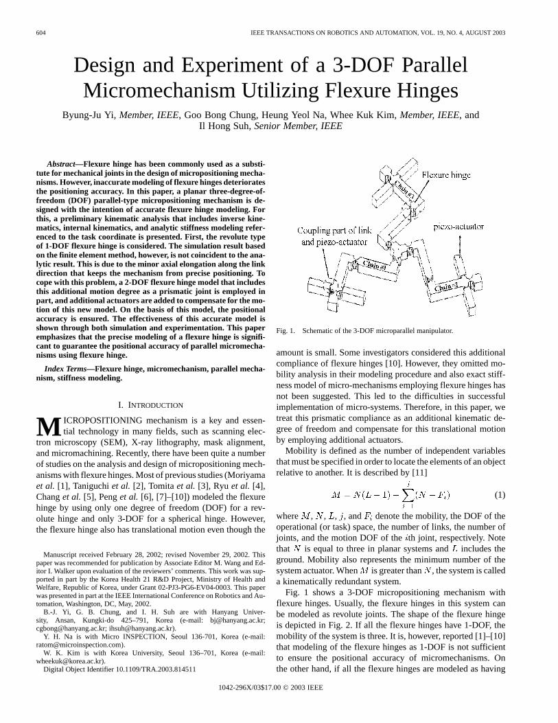
Fig. 1. Schematic of the 3-DOF microparallel manipulator.
amount is small. Some investigators considered this additionalcompliance of flexure hinges [10]. However, they omitted mo-bility analysis in their modeling procedure and also exact stiff-ness model of micro-mechanisms employing flexure hinges hasnot been suggested. This led to the difficulties in successfulimplementation of micro-systems. Therefore, in this paper, wetreat this prismatic compliance as an additional kinematic de-gree of freedom and compensate for this translational motionby employing additional actuators.
Mobility is defined as the number of independent variablesthat must be specified in order to locate the elements of an objectrelative to another. It is described by [11]
(1)
where , , , , and denote the mobility, the DOF of theoperational (or task) space, the number of links, the number ofjoints, and the motion DOF of theth joint, respectively. Notethat is equal to three in planar systems andincludes theground. Mobility also represents the minimum number of thesystem actuator. When is greater than , the system is calleda kinematically redundant system.
Fig. 1 shows a 3-DOF micropositioning mechanism withflexure hinges. Usually, the flexure hinges in this system canbe modeled as revolute joints. The shape of the flexure hingeis depicted in Fig. 2. If all the flexure hinges have 1-DOF, themobility of the system is three. It is, however, reported [1]–[10]that modeling of the flexure hinges as 1-DOF is not sufficientto ensure the positional accuracy of micromechanisms. Onthe other hand, if all the flexure hinges are modeled as having
YI et al.: DESIGN AND EXPERIMENT OF A 3–DOF PARALLEL MICROMECHANISM UTILIZING FLEXURE HINGES 605
Fig. 2. Schematic of the flexure hinge.
a revolute joint and a prismatic joint (in total, 2-DOF), themobility of the system is 12. Even though both finite elementmethod (FEM) analysis and theoretical analysis may give the2-DOF flexure hinge model more accurate results than the1-DOF flexure hinge model, the 12 actuators to control 3-DOFis expensive. Therefore, the flexure hinge should be designedin such a way that it not only minimize the number of actuators,but also ensures positional accuracy and sufficient workspace.In this paper, we design two types of flexure hinge. The firsttype is designed with relatively small cutting radius R of theflexure hinge and modeled as having 1-DOF. The second typehas 2-DOF by fabricating R relatively large. Consequently, thesecond type is modeled as having a 1-DOF revolute joint anda 1-DOF prismatic joint. If each chain of the system consistsof one 2-DOF hinge and two 1-DOF hinges, the mobility ofthe system is six. Therefore, it can be operated by only sixactuators.
This paper progresses as follows. Section II describes thesystem configuration. The kinematic analysis and analytic stiff-ness modeling of the 3-mobility and 6-mobility systems are per-formed in Sections III and IV), respectively. Section V presentsthe simulation results comparing the positioning accuracies ofthe 2-DOF and 1-DOF flexure hinge models and shows the meritof the proposed 6-mobility system. The effectiveness of this ac-curate model is shown through experimentation.
II. SYSTEM CONFIGURATION
The proposed 3-DOF parallel mechanism consists of a plat-form and three chains, each of which has three flexure hinges asshown in Fig. 1. This mechanism employs flexure hinges at alljoints and the joints are actuated by piezo actuators. The threechains are 120apart from each other. This symmetric structurereduces the effect of the temperature gradient and disturbance.The first and second hinges of each chain are antagonisticallyactuated by pair piezo-actuators. The first pair of actuators areattached to the base frame of the mechanism and the second pairattached to the second link. All actuators push the circular sur-face of each link for fine sliding and rotational motions.
Fig. 3. Modeling of the 3-DOF microparallel manipulator with mobility three.
The shape of one flexure hinge is shown in Fig. 2. The rota-tional displacement of the flexure hinge is defined as [12]
(2)
where and .The translational displacement in the X direction is de-
fined as
(3)
where .
III. K INEMATIC ANALYSIS FOR THE3-MOBILITY SYSTEM
In order to show the performance of the 1-DOF model of theflexure hinge, the kinematic model for the 3-mobility systemis introduced in Fig. 3. Since all flexure hinges are modeledwith 1-DOF, the mobility of the system is three. The kinematicanalysis of this case is performed in the following.
A. First-Order Kinematics
First-order kinematics relates the output velocity vector to theindependent joint velocity vector. In the following, denotesJacobian and the left subscript ofdenotes the number of se-rial subchain of the parallel manipulator. The superscript andsubscript on the right side of denote the dependent and inde-pendent parameters, respectively. Also, and
denote the th column and theth row of , respectively.denotes the (i, j) element of . denotes the an-
gular velocity of the th joint of the th chain. The velocity re-lation for each serial chain is described as
(4)
where the output velocity vector of the system and the angularvelocity vector of theth serial chain are defined asand , respectively.
606 IEEE TRANSACTIONS ON ROBOTICS AND AUTOMATION, VOL. 19, NO. 4, AUGUST 2003
Since the three serial chains have the same velocities at thecenter of platform, we have
(5)
and
(6)
Considering the three base joints as the independent joints,then, by rearranging (5) and (6), the velocity relation betweenthe independent joints and the dependent joints canbe obtained as
(7)
where
Embedding (7) into (4) yields
(8)
where
Finally, the relation of output and independent joint velocityis obtained as
(9)
B. Stiffness Model
Assume that the flexure hinges employed in Fig. 1 haveonly the rotational displacement about the z axis and that thedisplacements in the other directions are ignored. The flexurehinges employed at all joints can be considered as springs,and require force or moment to bend or expand (or compress)them. Therefore, in order to compute the input load to operatethis mechanism, we have to obtain the analytic stiffness modelreferenced to the output coordinate.
Let the stiffness matrix for theth chain be written as
(10)
where denotes the stiffness element of theth joint of theth chain. The independent joint stiffness matrix and dependent
joint stiffness matrix are composed, respectively, as
(11)
(12)
Then, in a state of equilibrium, the effective load referenced tothe independent joints is
(13)
where represents the externally applied loads, andandare the torque vectors at the independent and dependent joints,respectively. The behavior of an effective restoring forcecan be modeled as a spring action with respect to the system’sindependent inputs as follows:
(14)
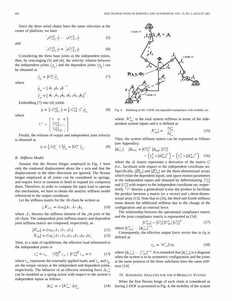
Fig. 4. Modeling of the 3-DOF microparallel manipulator with mobility six.
where is the total system stiffness in terms of the inde-pendent system inputs and it is defined as
(15)
Then, the system stiffness matrix can be expressed as follows(see Appendix):
(16)
where the matrix represents a derivative of the matrix(i.e., Jacobian) with respect to the independent coordinate set.Specifically, and are the three-dimensional arrayswhich relate the dependent inputs, task space motion parametersto the independent inputs and obtained by differentiatingand with respect to the independent coordinate set, respec-tively. “ ” denotes a generalized scalar dot product to facilitatethe product between a matrix (or a vector) and a three-dimen-sional array [13]. Note that in (16), the third and fourth stiffnessterms denote the additional stiffness due to the change of theconfiguration and an external force.
The relationship between the operational compliance matrixand the joint compliance matrix is represented as [14]
(17)
where .Consequently, the effective output force vector due tois
defined as
(18)
where . It is remarked that is a diagonalwhen the system is in its symmetric configuration and the jointsat the same position of the three subchains have the same stiff-ness [14].
IV. K INEMATIC ANALYSIS FOR THE6-MOBILITY SYSTEM
When the first flexure hinge of each chain is considered ashaving 2-DOF as presented in Fig. 4, the mobility of the system
YI et al.: DESIGN AND EXPERIMENT OF A 3–DOF PARALLEL MICROMECHANISM UTILIZING FLEXURE HINGES 607
TABLE IKINEMATIC PARAMETERS
is six. Note that the first flexure hinge of each chain has anadditional prismatic joint according to the elongation along theaxial direction. The kinematic analysis of this case is performedin the following.
A. First-Order Kinematics
For each chain, the center position (x, y) and the orientationangle of the platform is, respectively, given as
(19)
(20)
(21)
and the lengths of the virtual links of Fig. 3 are denoted as
where denotes the displacement of the prismatic joint ofthchain and denotes a fixed length of links.
Differentiating the above position equations with respect totime yields the first-order kinematic relation for each serialchain, given by
(22)
where , .Since the three serial subchains have the same output velocity
vectors at the center of the platform, we have
(23)
and
(24)
Here, we consider the first and third joints of each chain asthe independent joints. Thus, there are six independent joints.Then, by rearranging (23) and (24), the relation between theindependent joints and the dependent joints can beobtained as
(25)
where
Embedding (25) into (22) yields
(26)
where
Finally, the relation of output and independent joint velocityis obtained as
(27)
where
B. Inverse Kinematics
Given the center position (x, y) and the orientation angleof the platform, all of the joint positions of the parallel chain areobtained. An equivalent relation of (27) for infinitesimal motionis given by
(28)
In the 6-mobility system, the dimension of is greater thanthat of . Thus, the inverse of (28) is obtained as
(29)
where the weighted pseudoinverse solution of is given by
This represents an optimal solution that minimizes the poten-tial energy of the system subject to (28). represents an ef-fective stiffness matrix referenced to the six independent joints.It is given as (16).
Finally, the displacement of independent joints and dependantjoints are obtained as
(30)
and
(31)
C. Stiffness Model
The stiffness matrices of the independent joints and the de-pendent joints can be written as
(32)
and
(33)
respectively, where is the stiffness of the th joint of thchain.
For the 6-mobility system, the output compliance matrix andthe effective output force vector due to are identical to (17)and (18).
608 IEEE TRANSACTIONS ON ROBOTICS AND AUTOMATION, VOL. 19, NO. 4, AUGUST 2003
(a)
(b)
(c)
Fig. 5. Error analysis for X directional input.
V. SIMULATION
FEM is employed to verify the feasibility of the analytic stiff-ness model of the system. Given the virtual, infinitesimal dis-
(a)
(b)
(c)
Fig. 6. Error analysis for Y directional input. (a) X directional displacement.(b) Y directional error. (c)� directional error.
placement of the platform, the operational force vectorrequired to move the system can be calculated by (18).
Then, the force vector is applied to a virtual model in theFEM environment. Finally, a comparison of the output displace-ment vector of the FEM model with the initial displacement
YI et al.: DESIGN AND EXPERIMENT OF A 3–DOF PARALLEL MICROMECHANISM UTILIZING FLEXURE HINGES 609
given in the analytic model can test the feasibility of the ana-lytic stiffness model based on mobility analysis.
The workspace of the system is given in theand directions, and in the direction. Table I
denotes the kinematic parameters of the micromechanisms. Thesimulation results of FEM are shown in Figs. 5-7.
Fig. 8. Planar view of the 6-mobility mechanism.
Fig. 9. Close view of a subchain.
Fig. 10. Experimental setup.
The micromechanism with mobility three shows severe errorsin the commanding and all the other directions. On the otherhand, the micromechanism with mobility six shows negligibleerrors in the other directions, and a minor error of 510% inthe commanding direction. It is confirmed, therefore, that thesystem with mobility six has better precision than the systemwith mobility three.
610 IEEE TRANSACTIONS ON ROBOTICS AND AUTOMATION, VOL. 19, NO. 4, AUGUST 2003
Fig. 11. Stiffness obtained from experiment. (a) X directional stiffness. (b) Y directional stiffness. (c)� directional stiffness.
VI. EXPERIMENTS FORSTIFFNESSANALYSIS
Fig. 8 shows the 3-DOF, 6-mobility micromechanism devel-oped for experimental verification. This micromechanism, con-sisting of nine flexure hinges, was made by a wire-cutting ma-chine. Six sets of antagonistically driven piezo actuators are em-ployed. The stroke of the piezo actuator is 17.4. This allowsthe motion range in the and directions, and
in the direction.Note that in Fig. 9, the coupling between the actuator and the
link is frictionally engaged. Thus, it is possible to have someslip-stick effect, which may deteriorate the positioning accu-racy of the microsystems. However, the friction effect at eachcoupling is indispensable in this design because we have to at-tach six actuators to meet the number of mobility (6). In orderto minimize the stick-slip effect between the piezo actuator andthe link being pushed, a small ball is located at the contact pointof the link. Thus, a point contact with friction may be able tominimize the stick-slip effect.
In this section, we perform experiment to corroborate the ef-fectiveness of the simulation results. The objective of the exper-iment is to verify the trend and values of the operational stiffnessof the developed mechanism by comparing it with the stiffnesscalculated through simulation. Fig. 10 shows the experimentalsetup. The experiment to measure the operational stiffness is ex-ecuted as follows. A cylindrical pole is attached to the center of
TABLE IISTIFFNESSVALUES
the 6-mobility system. A horizontal bar is attached to the topof the pole to measure the rotational stiffness. The center ofthe pole is driven by a Piezo ceramic (PZT) actuator (PI brand:P-841.30) and the displacements of the end point are measuredby linear variable differential transformer (LVDT). Since themotor is rooted in a force/torque (F/T) sensor attached at theend-point of a manipulator, the stiffness of theand direc-tions can be calculated by dividing the measured force data bythe reaction forces measured in the F/T sensor.
The rotational stiffness is measured by pushing the horizontalbar and measuring the moment resulting from the rotation ofthe 3-DOF mechanism. Fig. 11 represents the experimental re-sults. The slopes denote the stiffness of the 3-DOF mechanismin each direction. It is remarked that the stiffness in theand
directions are identical, which corroborates the analytic resultreported previously [14].
YI et al.: DESIGN AND EXPERIMENT OF A 3–DOF PARALLEL MICROMECHANISM UTILIZING FLEXURE HINGES 611
The operational stiffness obtained from experimentation andsimulation is listed in Table II, where, , , and , de-notes the diagonal terms . As shown in Table II, the devia-tion between the operational stiffness obtained from experimen-tation and simulation based on the analytic model is around 10%on an average (2.6% inand directions and 31% in the rota-tional direction). The considerable error in the rotational direc-tion is anticipated since Fig. 7 denoting the displacement of therotational angle already shows some error in the rotational stiff-ness. It is also remarked that in the stiffness formulation givenin (16), the additional stiffness terms due to the change of theconfiguration and an external force affects the position error of3–5%. Thus, these terms should not be neglected.
Overall, the experimental results are shown more or less com-pliant as compared to the simulation results. There are severalpossibilities for this reason; In the manufacturing process, theflexure hinges may be in part plastically deformed. The linksconnecting the flexure hinges may also deflect. These issuesshould be further studied as future work.
VII. CONCLUSIONS
Inaccurate modeling of the flexure hinge does not assure theprecise motion of the micromechanism. In this paper, a planar3-DOF parallel-type micropositioning mechanism is proposedin consideration of accurate flexure hinge modeling. Initially, wehave shown through simulation that a planar 3-DOF micromech-anism having mobility three cannot assure the position accuracyof the system. On the other hand, the design having mobility sixexhibits good position accuracy. We performed the experimentto corroborate the effectiveness of the simulation results. Weconclude that accurate modeling enhances the position accuracyin the design of micromechanism. More precise modeling of theflexure hinge mechanism is necessary to enhance the positionalaccuracy of microsystems. It is expected that this device can beusefully employed for SEM, x-ray lithography, mask alignment,micromachining, and other similar technologies.
APPENDIX
where the externally applied load is given a constant value.
REFERENCES
[1] S. Moriyama, T. Harada, and T. Takanashi, “Precision X-Y stage with apiezo-driven fine-table,”Bull. Jpn. Soc. Precis. Eng., vol. 22, no. 1, pp.13–17, 1988.
[2] M. Taniguchi, M. Ikeda, A. Inagaki, and R. Funatsu, “Ultra precisionwafer positioning by six-axis micro-motion mechanism,”Int. J. Jpn.Soc. Precis. Eng., vol. 26, no. 1, pp. 35–40, 1992.
[3] Y. Tomita, F. Sato, K. Ito, and Y. Koyanagawa, “Decoupling method ofultraprecision stage using parallel linkage mechanism,”Int. J. Jpn. Soc.Precis. Eng., vol. 26, no. 1, pp. 47–53, 1992.
[4] J. W. Ryu, S.-Q. Lee, D.-G. Gweon, and K. S. Moon, “Inverse kinematicmodeling of a coupled flexure hinge mechanism,”Mechatronics, vol. 9,pp. 657–674, 1999.
[5] S. H. Chang, C. Kai, and H. C. Chien, “An ultra-precisionXY � piezo-micropositioner—Part I: Design and analysis,”IEEE Trans. Ultrason.,Ferroelect., Freq. Contr., vol. 46, pp. 897–905, July 1999.
[6] V. T. Portman, B.-Z. Sandler, and E. Zahavi, “Rigid 6� 6 parallel plat-form for precision 3-D micromanipulation: theory and design applica-tion,” IEEE Trans. Robot. Automat., vol. 16, pp. 629–643, Dec. 2000.
[7] E. Pernette, S. Henein, I. Magnani, and R. Clavel, “Design of parallelrobots in microrobotics,”Robotica, vol. 15, no. 4, pp. 417–420, 1997.
[8] J. Hesselbach and A. Raatz, “Pseudoelastic flexure-hinges in robots formicro assembly,” inProc. SPIE Microrobotics and Microassembly II,vol. 4914, 2000, pp. 157–167.
[9] P. Gao, S.-M. Swei, and Z. Yuan, “A new piezo-driven precision microp-ositioning stage utilizing flexure hinges,”Nanotechnology, vol. 10, pp.394–398, 1999.
[10] M. Gogola and M. Goldfarb, “Design of a PZT-actuated proportionaldrum brake,”IEEE/ASME Trans. Mechatron., vol. 4, pp. 409–416, Apr.1999.
[11] A. G. Erdman and G. N. Sandor,Mechanical Design: Analysis and Syn-thesis, 2nd ed. Englewood Cliffs, NJ: Prentice-Hall, 1991, vol. 1.
[12] J. M. Paros and L. Weisbord, “How to design flexure hinge,”Mach. Des.,vol. 37, pp. 151–157, 1965.
[13] B.-J. Yi and R. A. Freeman, “Geometric analysis of antagonistic stiffnessin redundantly actuated parallel mechanisms,”J. Robot. Syst., vol. 10,pp. 581–603, 1993.
[14] W. K. Kim, B.-J. Yi, and W. Cho, “RCC characteristics of planar/spher-ical three degree-of-freedom parallel mechanisms with joint compli-ances,”ASME J. Mech. Des., vol. 122, pp. 10–16, Mar. 2000.
Byung-Ju Yi (S’89–M’89) received the B.S. degreefrom the Department of Mechanical Engineering,Hanyang University, Seoul, Korea in 1984, and theM.S. and Ph.D. degrees from the Department ofMechanical Engineering, University of Texas atAustin, in 1986 and 1991, respectively.
From January 1991 to August 1992, he was a Post-Doctoral Fellow with the Robotics Group, Universityof Texas at Austin. From September 1992 to February1995, he was an Assistant Professor in Department ofMechanical and Control Engineering, Korea Institute
of Technology and Education (KITE), Chonan, Chungnam, Korea. In March1995, he joined Hanyang University, Ansan, Kyungki-do, Korea as an AssistantProfessor in the Department of Control and Instrumentation Engineering. Cur-rently, he is an Associate Professor with the School of Electrical Engineeringand Computer Science, Hanyang University. His research interests include de-sign, control, and application of multiple arms, parallel manipulator, microma-nipulator, haptic device, anthropomorphic manipulator, and surgical robot sys-tems.
Goo Bong Chung received the B.S. and M.S.degrees in 1998 and 2000, respectively, from theDepartment of Control and Instrumentation Engi-neering, Hanyang University, Seoul, Korea, wherehe is currently working toward the Ph.D. degree.
His research interests include parallel manipu-lators, kinematics, dynamics and control of hybridsystems, design of micromanipulators, robust controlof robots, redundant manipulators, and surgicalrobot systems.
612 IEEE TRANSACTIONS ON ROBOTICS AND AUTOMATION, VOL. 19, NO. 4, AUGUST 2003
Heung Yeol Na received the B.S. degree from theDepartment of Mechanical and Control Engineering,Korea Institute of Technology and Education(KITE), Chonan, Chungnam, Korea in 1998, andthe M.S. degree from the Department of Control andInstrumentation Engineering, Hanyang University,Seoul, Korea, in 2001.
He is now a researcher of MicroINSPECTION,Inc., Seoul, Korea. His research interests includeparallel manipulators, the kinematics, dynamics, andcontrol of hybrid systems, micromanipulators, and
robust control of robot manipulators.
Whee Kuk Kim (M’90) received the B.S. degreein mechanical engineering from Korea University,Seoul, Korea, in 1980, and the M.S. and Ph.D. de-grees in mechanical engineering from the Universityof Texas at Austin, in 1985 and 1990, respectively.
Since 1991, he has been with Department of Con-trol and Instrumentation Engineering, Korea Univer-sity, Chochiwon, Korea, where he is currently a Pro-fessor. His current research interests are in the areaof design of parallel robots, kinematic/dynamic mod-eling, and analysis of parallel/mobile/walking robots.
Il Hong Suh (M’89–SM’02) was born in Seoul,Korea. He received the B.S. degree in electronicsengineering from Seoul National University, Seoul,Korea, in 1977 and the M.S. and Ph.D. degrees inelectrical engineering from the Korea Institute ofScience and Technology (KAIST), Seoul, Korea, in1979 and 1982, respectively.
From 1982 to 1985, he was a Senior Research En-gineer at the Technical Center of Daewoo Heavy In-dustries, Ltd., Inchon, Korea, where he was involvedin research work in machine vision and the develop-
ment of the Daewoo NOVA10 robot controller. From 1985 to 1986, he was withthe Systems Control Laboratory, KAIST, as a part-time Research Fellow foran automation-related Korea National Project. In 1987, he was a Visiting Re-search Fellow at the Robotics Division, CRIM, University of Michigan, AnnArbor. Since 1985, he has been with the Department of Electronics Engineering,Hanyang University, Ansan, Kungki-do, Korea, where he is a Professor, Hisresearch interests include sensor-based control of robot manipulators, coordi-nation of multiple robot arms, robot control intelligent control involving fuzzylogics, and neural networks.