Abstract— This paper focuses on the design and experimental evaluation of a hydraulically actuated robot leg. The evaluation of the leg prototype is an important milestone in the development of HyQ, a Hydraulically actuated Quadruped robot. The prototype features two rotary joints actuated by hydraulic cylinders and has a mass of 4.5kg. We performed several experiments with the leg prototype attached to a vertical slider to tests the robustness of the mechanical design and the hydraulic actuation system. Besides the experimental evaluation of the hydraulic components, we also extensively studied the sensor data of the leg during periodic hopping. The results show that hydraulic actuation is suitable for legged robots because of its high power-to-weight ratio, fast response and ability to cope with high impact force peaks. Furthermore, we compare the cylinder force data obtained by the load cell with the calculated value based on the cylinder pressures to analyze if it is possible to eliminate this sensory system redundancy in the future. Through these studies, weaknesses of the design were identified and suggestions on how to improve them are presented.
HE joints in most current robots are powered by electric actuators, which are popular because they are
inexpensive, available in a large range of sizes, accurate and easy to control. They produce high speeds, but often very small torques relative to their size and weight [1]. Therefore reduction gears are necessary to convert speed into torque. These gears, however, introduce undesired friction and backlash to the actuator unit and reduce its efficiency and backdrivability. In fact, these gears are increasingly becoming one of the weakest elements of an electric motor assembly [2].
The actuators needed for legged robots, especially those designed for highly dynamic, heavy-duty tasks such as running and jumping, must be robust enough to cope with the large impact force peaks developed during foot touch-down. But reduction gears can be easily damaged if subjected to excessive torque peaks and are therefore less suitable for those highly dynamic legged robots.
Claudio Semini is with the Italian Institute of Technology, Via Morego
Nikos G. Tsagarakis, Emanuele Guglielmino and Darwin G. Caldwell are with the Italian Institute of Technology, Via Morego 30, 16163 Genoa, Italy (email: {nikos.tsagarakis, emanuele.guglielmino, darwin.caldwell}@iit.it).
Researchers have developed several solutions to tackle this problem: mechanical springs in series with the electric motor or fluidic actuators such as pneumatics or hydraulics. The former technique has been successfully employed in several hopping and running robots.
The ARL monopod was an electrically actuated planar robot with a spring in its prismatic leg, which was able to hop at a top speed of 1.2m/s. It was the fastest electrically actuated legged robot at that time [3]. More recent robots using this approach include the ECD leg with leaf springs [4] and the quadruped robot KOLT that was able to perform trotting [5].
Pneumatic and hydraulic actuators are driven by a pressurized fluid, such as air or oil, respectively. The compressibility of these fluids gives the actuator a certain degree of intrinsic compliance. While air is easily compressed, oil is rather stiff. The dynamic response of an oil-hydraulic system strongly depends on the volumes inside the hydraulic tubing and on the bulk modulus (the reciprocal of compressibility) of the oil, which is related to the amount of entrapped air and the hose elasticity [6]. Hydraulic actuation systems work with high pressures of around 20MPa usually (but can reach up to 70MPa in some systems). This results in actuators with very high power-to-weight ratios and fast response. These properties together with the intrinsic compliance make hydraulic actuators very suitable candidates for highly dynamic legged robots.
In the 1980’s, Raibert and his team at CMU and later MIT developed a series of pneumatic and hydraulic legged robots that were able to balance actively, hop in 3D (monopod), perform a somersault (biped) and run with several gaits such as trotting, pacing and bounding (quadruped) [7]. They used hydraulic actuators for leg positioning and thrust and pneumatic springs for compliance and energy storage.
In the late 1990’s, Hyon et al. constructed KENKEN, a hydraulically powered planar monopod with a bio-inspired leg design including mechanical springs. It successfully performed hopping attached to a boom [8]. Sarcos constructed several hydraulically actuated humanoid robots (e.g. CB, DB), which are used to study active balance and dynamic full body motions [9]-[11].
In recent years, Raibert et al. at Boston Dynamics regularly stun the public with impressive videos of their quadruped robot BigDog. The newest version of this hydraulically actuated robot is roughly 1.1m long, 0.3m wide and 1.0m high and weighs approximately 110kg. Its actuation system is powered by an onboard combustion
Design and Experimental Evaluation of the Hydraulically Actuated Prototype Leg of the HyQ Robot
Claudio Semini, Nikos G. Tsagarakis, Emanuele Guglielmino and Darwin G. Caldwell
T
The 2010 IEEE/RSJ International Conference on Intelligent Robots and Systems October 18-22, 2010, Taipei, Taiwan
engine, which makes it power-autonomous for up to 2.5 hours [12]. It is able to run with a trotting or bounding gait, move on rough and inclined terrain and keep its balance on snow, ice and after a strong lateral kick. The goal of the project is to create a robotic mule that is able to carry the equipment for, and autonomously follow, soldiers on various kinds of terrain [13]. While the videos of BigDog are highly popular on the internet, unfortunately little details about the robot design, specifications and control has been published.
We are currently constructing a quadruped robot (called HyQ) with a combination of hydraulic and electric actuators. Each leg has two hydraulic degrees of freedom (DOF) in the hip and knee flexion/extension joints and one electric DOF for the hip abduction/adduction joint. The goal of the project is to develop a robotic platform of the size of a goat or small pony that is able to perform highly dynamic tasks like jumping, hopping and running. Besides the study of quadrupedal locomotion, balance and energy-efficiency, the robot will serve as a platform to test the applicability of compact hydraulic components for legged robots. Possible applications are search and rescue missions in disaster areas, demining, transport of humanitarian goods and various other tasks in dangerous environments to the human. More details about the project are reported in [2][14].
A first milestone was the construction of a leg prototype to test the mechanical design and hydraulic actuation system and to evaluate its potential to enable the robot to perform highly dynamic tasks. This paper presents the leg design with a focus on the hydraulic actuation and shows the experimental results of several studies with the leg attached to a slider.
The paper is organized as follows: section II gives an overview of biological studies on quadruped animals. Section III presents the design, components and kinematics of the hydraulic prototype leg and section IV shows the results of several experiments. Section V addresses the conclusions and comments on future work.
II. QUADRUPEDAL LOCOMOTION IN NATURE
Nature has come up with a vast range of different quadruped animals with impressive abilities: The cheetah for example is the fastest land animal capable of running with a speed of up to 120km/h. Mountain goats have great climbing and balancing skills, cats are very agile and horses are able to carry heavy loads.
Biologists are extensively studying their bio-mechanical leg structure and locomotion abilities. These reports are a valuable source for legged robot designers. They do not only provide functional information about the body and limbs, but also constitute a useful base for specifications in terms of body mass/size in relation to locomotion performance.
The trot gait, which pairs diagonal legs, exhibits good energy efficiency over a wide range of running speeds, shows no significant pitch or roll motion during each stride
and is therefore often seen in nature [15]. According to a study of a large range of quadruped animals, a selection of common trotting speeds and stride frequencies can be calculated in relation to the animal’s body mass [16]. The estimated weight of HyQ with onboard hydraulic pump is 80kg, which results in the following approximations for forward velocity and stride frequency:
• minimum trotting gait 1.77 m/s 1.62 Hz • preferred trotting gait 2.88 m/s 1.90 Hz • maximum trotting gait 3.97 m/s 2.17 Hz
Force plate measurements of trotting dogs indicate vertical ground reaction forces as shown in Fig. 1 for the fore (front) and hind (back) limbs. Note that the force is expressed in multiples of body weight.
Fig. 1. Vertical ground reaction force (expressed in body weight) of a
trotting dog during a single step plotted against time. Circles indicate forelimb (front leg) force and squares hind limb (back leg) force. Horizontal lines indicate the mean ground reaction force. (Adapted from [17])
The force peak of the front legs is 1.2 times the body weight, which corresponds to approximately 940N for HyQ.
We will use these findings in section IV to compare them with our experimental results.
III. DESIGN OF HYDRAULIC ROBOT LEG
This section presents the leg prototype and its specifications, the hydraulic actuation system, leg kinematics and control system. Fig. 2 shows a picture of the prototype leg attached to a vertical slider (left) and a schematic with an explanation of the leg parts and components (right).
Table I summarizes the specifications of the robot leg with reference to the joint angle and leg segment lengths in Fig. 5.
A. Mechanical Design The majority of the mechanical structure of the robot leg is
constructed in ERGAL, an aluminum alloy (code 7075), that is widely used in the aerospace industry due to its excellent strength-to-weight ratio (e.g. in the wings and fuselage of a Boeing 747). It has a density of 2810kg/m3 and yield stress up to 520MPa. Critical parts that are heavily stressed are made in stainless steel (17-4 PH) with a density of 7800kg/m3 and yield stress up to 1240MPa.
Time [s]
Ver
tical
gro
und
forc
e [b
ody
wei
ght]
3641
Fig. 2. Picture of the 2-DOF leg prototype fixed to a vertical slider (left)
and leg sketch on the right showing the three leg segments: hip assembly (1), upper leg (2) and lower leg (3), the hip and knee cylinder (4,5), the hip and knee joint axis with encoders (6), the load cells (7) and the robot foot (8).
TABLE I SPECIFICATIONS OF ROBOT LEG PROTOTYPE
Degrees of freedom (DOF) 2 (hydraulic)
Hip joint range of motion (q1) -70° to 50°
Knee joint range of motion (q2) 20° to 140°
Leg segments lengths (l1, l2) 0.3m
Position sensors 2 relative encoders (80000counts/rev)
Force/torque sensors 2 load cells (4440N max)
Pressure sensors 4 sensors (25MPa max)
Theoretical maximum joint torque at 160 bar (extending) 125Nm
Theoretical maximum joint torque at 160 bar (contracting) 77Nm
Total weight of leg (hip assembly, upper leg and lower leg) 4.4kg
Weight of upper leg segment including knee cylinder 1.5kg
Weight of lower leg segment 0.8kg
The leg consists of three main parts: hip assembly, upper
leg and lower leg, as shown in Fig. 2. The leg uses a tubular construction (hip assembly and lower leg) and a pair of parallel plates that are connected by horizontal shafts, as shown on the CAD model, Fig. 3. The cylinders are mounted between the leg plates and fixed to these steel shafts (diameter 8mm). The tubes have a diameter of 30mm, a thickness of 5mm and constitute a strong but light-weight leg structure. The parallel plate structure is weaker in terms of torsional and axial deflection but allows the cylinders to be accommodated internally. Two bearings per joint provide a robust and low-friction connection of the leg segments. The foot is hemispherical with a diameter of 40mm. It is rigidly connected to the lower leg and has a visco-elastic rubber coating to dampen the impacts at touchdown and protect the structure from the force peaks.
Fig. 3. CAD model of the leg prototype with the explanation of some of
the mechanical design features.
B. Hydraulic Actuation System
Fig. 4 shows the scheme of the hydraulic system with the explanation of all system components. The two double-acting hydraulic cylinders (Hoerbiger LB6-1610-0080-4M) have a bore/rod diameter of 16mm/10mm and a stroke length of 70mm. Their maximum permitted operating pressure is 16MPa. The pressure inside the cylinder chambers (PA and PB) is measured by pressure sensors (see section 3.E). Two proportional 4-way spool valves (Wandfluh WDPFA03-ACB-S5-G24) mounted on a valve manifold control the flow to the valves.
The hydraulic pressure is generated by a volumetric pump with a flow rate of 6 l/min connected to a relief valve with an adjustable pressure range of 2 to 21MPa. A 0.5l accumulator provides extra flow if needed and reduces pressure ripples. The heat exchanger keeps the oil temperature at a constant 45°C.
C. Control System and Sensors
Joint control uses two proportional valves, which adjust the hydraulic flow to the cylinders. The solenoids of these valves are controlled by a PWM signal generated by a Sensoray 526 multi I/O board connected to a PC104 Pentium board that runs a 1kHz control loop. Analog sensor data is sampled by the I/O board with a 16Bit resolution.
The angular position of the joints is measured by relative encoders (Avago AEDA-3300BE1) with a high-resolution of 80’000 counts/rev. The pressure sensors (Trafag 8251-74-2517) have an accuracy of ±0.5% and a range of 0-25MPa. The cylinder force is measured by tension/compression load cells (Honeywell Sensotec Model 11) with a range of ±4440 N and an accuracy of ±0.5%. The slider height is measured by an absolute encoder (AustrianMicroSystems AS5045) connected to a steel cable and pulley system.
parallel plates
tubular structure of hip assembly
cylinder attachment shafts
tubular structure of lower leg
visco-elastic rubber coated foot
low friction ball bearing joints
3642
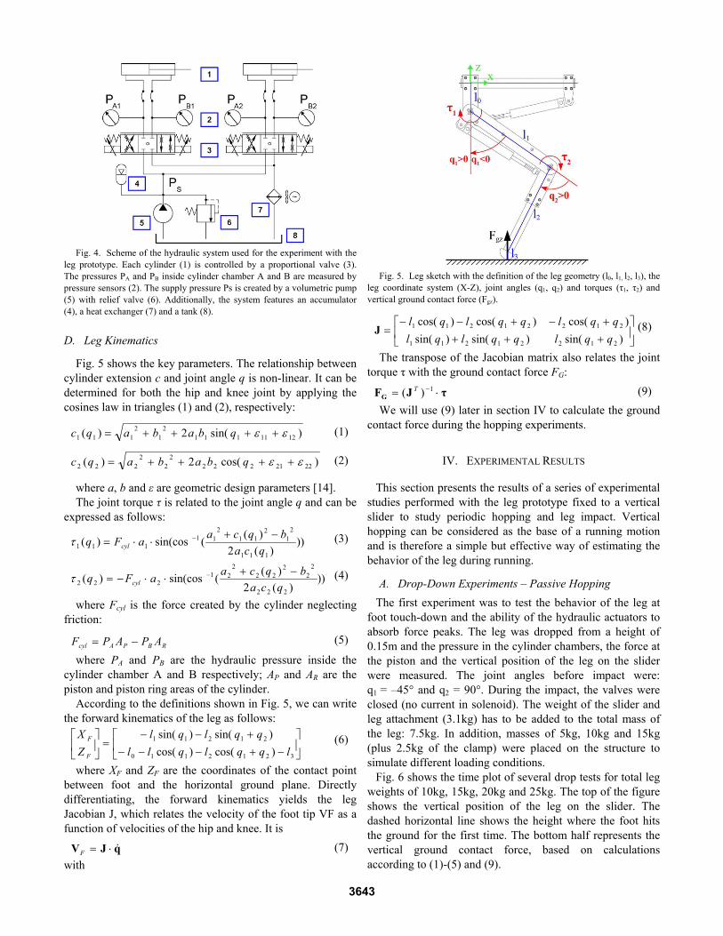
Fig. 4. Scheme of the hydraulic system used for the experiment with the leg prototype. Each cylinder (1) is controlled by a proportional valve (3). The pressures PA and PB inside cylinder chamber A and B are measured by pressure sensors (2). The supply pressure Ps is created by a volumetric pump (5) with relief valve (6). Additionally, the system features an accumulator (4), a heat exchanger (7) and a tank (8).
D. Leg Kinematics
Fig. 5 shows the key parameters. The relationship between cylinder extension c and joint angle q is non-linear. It can be determined for both the hip and knee joint by applying the cosines law in triangles (1) and (2), respectively:
)sin(2)( 12111112
12
111 εε ++++= qbabaqc
(1)
)cos(2)( 22212222
22
222 εε ++++= qbabaqc
(2)
where a, b and ε are geometric design parameters [14]. The joint torque τ is related to the joint angle q and can be
expressed as follows:
)))(2
)((sin(cos)(111
21
211
211
111 qcabqcaaFq cyl
−+⋅⋅= −τ
(3)
)))(2
)((sin(cos)(222
22
222
221
222 qcabqcaaFq cyl
−+⋅⋅−= −τ
(4)
where Fcyl is the force created by the cylinder neglecting friction:
RBPAcyl APAPF −=
(5)
where PA and PB are the hydraulic pressure inside the cylinder chamber A and B respectively; AP and AR are the piston and piston ring areas of the cylinder.
According to the definitions shown in Fig. 5, we can write the forward kinematics of the leg as follows:
⎥⎦
⎤⎢⎣
⎡−+−−−
+−−=⎥
⎦
⎤⎢⎣
⎡
3212110
21211
)cos()cos()sin()sin(
lqqlqllqqlql
ZX
F
F
(6)
where XF and ZF are the coordinates of the contact point between foot and the horizontal ground plane. Directly differentiating, the forward kinematics yields the leg Jacobian J, which relates the velocity of the foot tip VF as a function of velocities of the hip and knee. It is
qJV &⋅=F
(7) with
Fig. 5. Leg sketch with the definition of the leg geometry (l0, l1, l2, l3), the leg coordinate system (X-Z), joint angles (q1, q2) and torques (τ1, τ2) and vertical ground contact force (Fgz).
⎥⎦
⎤⎢⎣
⎡++++−+−−
=)sin()sin()sin()cos()cos()cos(
21221211
21221211
qqlqqlqlqqlqqlql
J
(8)
The transpose of the Jacobian matrix also relates the joint torque τ with the ground contact force FG:
τJFG ⋅= −1)( T
(9) We will use (9) later in section IV to calculate the ground
contact force during the hopping experiments.
IV. EXPERIMENTAL RESULTS
This section presents the results of a series of experimental studies performed with the leg prototype fixed to a vertical slider to study periodic hopping and leg impact. Vertical hopping can be considered as the base of a running motion and is therefore a simple but effective way of estimating the behavior of the leg during running.
A. Drop-Down Experiments – Passive Hopping
The first experiment was to test the behavior of the leg at foot touch-down and the ability of the hydraulic actuators to absorb force peaks. The leg was dropped from a height of 0.15m and the pressure in the cylinder chambers, the force at the piston and the vertical position of the leg on the slider were measured. The joint angles before impact were: q1 = –45° and q2 = 90°. During the impact, the valves were closed (no current in solenoid). The weight of the slider and leg attachment (3.1kg) has to be added to the total mass of the leg: 7.5kg. In addition, masses of 5kg, 10kg and 15kg (plus 2.5kg of the clamp) were placed on the structure to simulate different loading conditions.
Fig. 6 shows the time plot of several drop tests for total leg weights of 10kg, 15kg, 20kg and 25kg. The top of the figure shows the vertical position of the leg on the slider. The dashed horizontal line shows the height where the foot hits the ground for the first time. The bottom half represents the vertical ground contact force, based on calculations according to (1)-(5) and (9).
3643
Fig. 6. Time plots of the vertical leg position and vertical ground contact
force for the leg dropped from 0.15m. The joint angles before impact were: q1 = –45° and q2 = 90°. The experiment has been repeated with additional weights attached to the leg, resulting in a mass of 10kg, 15kg, 20kg, 25kg.
The time plots show that the compliance (both stiffness and damping) in the hydraulic system damps the impact peaks and even makes the leg bounce off the floor like an elastic ball. The ground force profile shows this elastic contact and more importantly reveals force profiles and amplitudes comparable to those in the trotting dog study of Fig. 1.
Next, we are considering the resulting force in the cylinders measured by the load cell and the calculated force based on the pressure sensor data and (5). Fig. 7 shows the two force profiles for the knee cylinder for the previous experiments.
Fig. 7. Force in the knee cylinder measured with the load cell (solid line) and calculated based on the cylinder chamber pressures (dashed line) of the experiments shown in Fig. 6.
The plot shows that the load cell saturates at around 3.5kN. For lower values the force profiles are almost identical, but for static measurements the curves differ due to the neglected static cylinder friction. We conclude that the pressure sensor data is sufficient to accurately estimate the cylinder force during dynamic motions. Whether the pressure sensor data will permit smooth force control (and as a consequence the load cell can be eliminated) is part of future work.
B. Active Hopping Trials
Let us now discuss the results of a second series of experiments with the leg prototype. We repeated the above mentioned experiments with an active PD-position control loop and the joint angle reference set to q1ref = –45° and q2ref = 90°. With empirical tuning of some system parameters (controller gains, supply pressure etc.), the leg can be forced to start continuously hopping (entering a limit cycle [18])
after the initial impact. After drops from different heights, the leg enters a parameter-dependent limit cycle with a constant frequency and amplitude. We will use this experiment to test the behavior of the leg during hopping, since these motion profiles and forces are strongly related to those of running.
Fig. 8 shows the time plot of the leg dropped from 0.17m that starts continuous hopping with constant amplitude after 3-4 cycles. The supply pressure Ps was set to 16MPa and the total leg mass was 15kg. The proportional and derivative controller gains were set to kp1=2.0, kd1=1.0 for the hip and kp2=2.0, kd2=1.5 for the knee joint.
Fig. 8. Time plots of the vertical leg position and vertical ground contact force for the leg dropped from 0.17m and then entering a period hopping motion with constant frequency and amplitude. The total leg mass is 15kg and the pressure supply set to 16MPa. The joint angles are PD-position controlled with q1ref = –45° and q2ref = 90°.
The periodic hopping motion converged to an amplitude of
0.1m after less than 2s and kept a constant frequency of 2.75Hz. Comparison with the stride frequencies of trotting dogs (section II) confirmed that the leg prototype is capable of performing comparably fast and strong continuous hopping motions, that have been observed in running 80kg quadrupeds. Fig. 9 shows a picture sequence of the prototype leg during one hopping cycle with slightly different system parameters (lower leg mass and higher knee proportional gain), resulting in a hopping frequency of 2.3Hz.
We further investigated the limit cycle behavior for different values of the system parameters. Fig. 10 shows the phase plot of the continuous hopping motion (as also used by Raibert [7]) for different supply pressures (8MPa, 10MPa, 12MPa, 14MPa, 16MPa).
The plot shows that the supply pressure is directly related to the hopping amplitude.
V. CONCLUSIONS AND FUTURE WORK
This paper presents the design of a hydraulically actuated leg for a quadruped robot and its experimental evaluation. We have shown through leg impact tests and continuous hopping experiments that the mechanical structure of the leg is strong enough for heavy-duty and highly dynamic tasks, such as running or jumping. Furthermore we have concluded that hydraulic cylinders are suitable actuators for the joints
3644
Fig. 9. Picture sequence of the HyQ Leg prototype clamped to the vertical slider test bench, performing periodic hopping with 2.3Hz. Supply pressure: 16MPa, leg weight: 12.5kg, knee controller gain kp2= 3.0 and joint angle reference at q1ref = –45° and q2ref=90°. The sequence shows one hopping cycle. Time between two frames: 80ms. This experiment is also shown in the accompanying video of this paper.
Fig. 10. Phase plot of continuous hopping experiments showing the
vertical leg position against vertical leg speed for different supply pressures. Time progresses in counter-clockwise direction. The dashed horizontal line shows the height where the foot hits the ground.
of legged robots, especially due to their ability to cope with high impact force peaks; an important ability that electric motor actuators with gears do not currently possess.
We have compared the cylinder force data obtained using a load cell with those obtained by pressure sensors measuring the cylinder chamber pressures. This study has shown a high degree of congruence during fast motions and a steady state error for the static case due to the neglected cylinder friction. Future force control experiments based on either data will confirm if the load cell is redundant and can be eliminated in future versions.
The experiments also revealed that this current load cell and amplifier saturate because their maximum range is too low and a greater range will be used in future. The incorporation of an electro-mechanical switch in the foot is important to switch controllers between ground contact and air phase and for easier data analysis.
Future works will involve full testing of the quadruped robot with leg improvements based on the findings of this work. Furthermore, we are currently studying the limit cycle hopping in more depth to assess the full potential of this model in producing controllable energy efficient motion.
When fully operational the quadruped robot HyQ will be tested in walking, jumping and trotting experiments on a treadmill. We are especially interested in the investigation of energy-efficiency of different locomotion gaits in relation to
the running speed and the importance of compliant elements in the leg.
REFERENCES
[1] C. Mavroidis, C. Pfeiffer and M. Mosley, “Conventional Actuators, Shape Memory Alloys and Electrorheological Fluids,” Invited Chapter in Automation, Miniature Robotics and Sensors for Non-Destructive Testing and Evaluation, Y. Bar-Cohen Editor, pp. 189-214, 2000.
[2] C. Semini, “HyQ – Design and Development of a Hydraulically Actuated Quadruped Robot,” Dissertation, Italian Institute of Technology and University of Genoa, 2010.
[3] P. Gregorio, M. Ahmadi and M. Buehler, “Design, control, and energetics of an electrically actuated legged robot,” IEEE Transactions on Systems Man and Cybernetics, Part B, pp. 626-634, 1997.
[4] J.W. Hurst and A.A. Rizzi, “Series compliance for an efficient running gait,” IEEE Robotics & Automation Mag., Vol. 15, pp. 42-51, 2008.
[5] J. Estremera and K.J. Waldron, “Thrust control, stabilization and energetics of a quadruped running robot,” Int. J. of Robotics Research, Vol. 27, 2008.
[6] H. Merritt, “Hydraulic Control Systems,” John Wiley & Sons, 1967. [7] M. Raibert, “Legged Robots That Balance,” The MIT Press, 1986. [8] S.H. Hyon, T. Emura and T. Mita, “Dynamics-based control of a one-
legged hopping robot,” J. Syst. Ctrl. Eng., Vol. 217, pp. 83-89, 2003. [9] G. Cheng, S.H. Hyon, J. Morimoto, A. Ude, J.G. Hale, G. Colvin, W.
Scroggin and S.C. Jacobsen, “CB: a humanoid research platform for exploring neuroscience,” Advanced Robotics Journal, Vol. 21, pp. 1097-1114, 2007.
[10] D.C. Bentivegna, C.G. Atkeson and J. Y. Kim, “Compliant Control of a hydraulic humanoid joint”, IEEE-RAS 7th Int. Conf. on Humanoid Robots (Humanoids), 2007.
[11] S.H. Hyon, “A Motor Control Strategy with Virtual Musculoskeletal Systems for Compliant Anthropomorphic Robots,” IEEE/ASME Transactions on Mechatronics, Vol. 14(6), 2009.
[12] M. Raibert, K. Blankespoor, G. Nelson, R. Playter and the BigDog Team, “BigDog, The Rough-Terrain Quadruped Robot,” Proceedings of IFAC World Congress, pp. 10822-10825, 2008.
[13] M. Buehler, R. Playter and M. Raibert, “Robots Step Outside,” Int. Symp. on Adaptive Motion of Animals and Machines (AMAM), 2005.
[14] C. Semini, N.G. Tsagarakis, B. Vanderborght, Y.S. Yang and D.G. Caldwell, “HyQ – Hydraulically Actuated Quadruped Robot: Hopping Leg Prototype,” IEEE/RAS Int. Conf. on Biomedical Robotics and Biomechatronics (BioRob), pp.593-599, 2008.
[15] L.R. Palmer, “Intelligent Control and Force Redistribution for a High-Speed Quadruped Trot,” Dissertation, Ohio State University, 2007.
[16] N. Heglund and C. Taylor, “Speed, stride frequency and energy cost per stride: How do they change with body size and gait?” J. Exp. Biol, Vol. 138(1), pp. 301-318, 1988.
[17] D.V. Lee, J.E. Bertram and R.J. Todhunter, “Acceleration and balance in trotting dogs,” J. of Exp. Biology, Vol. 202, pp. 3565–3573, 1999.
[18] J.J. Slotine and W. Li, “Applied Nonlinear Control,” Prentice Hall, 1991.