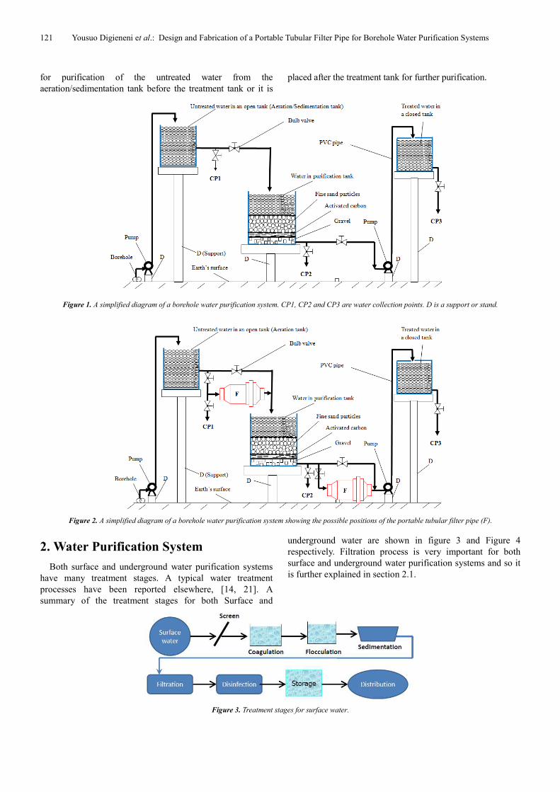
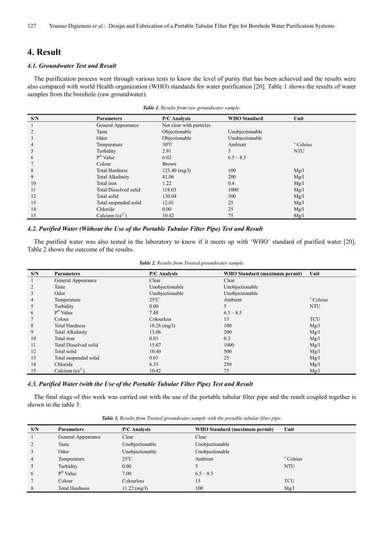
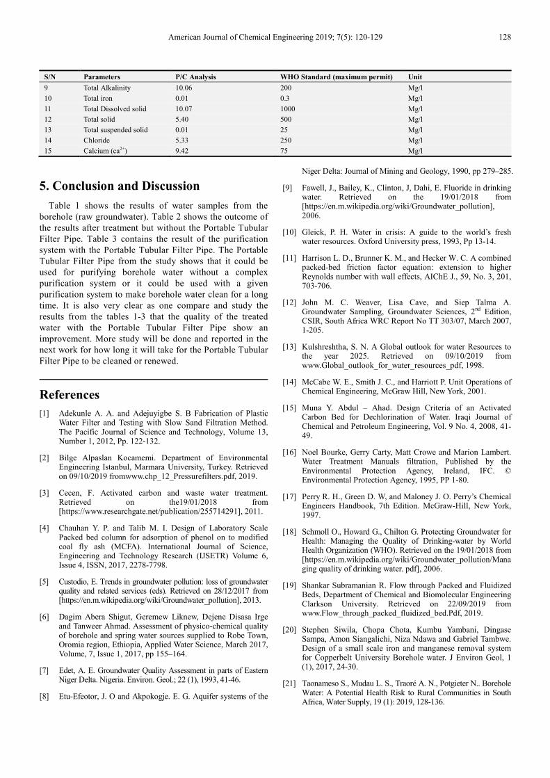
American Journal of Chemical Engineering 2019; 7(5): 120-129 http://www.sciencepublishinggroup.com/j/ajche doi: 10.11648/j.ajche.20190705.11 ISSN: 2330-8605 (Print); ISSN: 2330-8613 (Online) Design and Fabrication of a Portable Tubular Filter Pipe for Borehole Water Purification Systems Yousuo Digieneni * , Orlando Ketebu, Farrow Timipere Salome Department of Chemical Engineering, Niger Delta University, Yenagoa, Nigeria Email address: * Corresponding author To cite this article: Yousuo Digieneni, Orlando Ketebu, Farrow Timipere Salome. Design and Fabrication of a Portable Tubular Filter Pipe for Borehole Water Purification Systems. American Journal of Chemical Engineering. Vol. 7, No. 5, 2019, pp. 120-129. doi: 10.11648/j.ajche.20190705.11 Received: October 11, 2019; Accepted: October 29, 2019; Published: November 5, 2019 Abstract: Two main sources of water (the surface water and underground water) were briefly discussed in this paper. Filtration which is a very significant treatment process for both surface water and underground water was also discussed. A portable tubular filter pipe for borehole water purification system was designed and fabricated. The materials used in the portable tubular filter pipe (sand layer depth of 0.15m of size 0.8 – 2mm and coarse gravel layer depth of 0.02m of size 5- 8mm) were sourced locally. The coarse aggregate (gravel) layer served as support and distribution of water while the sand layer served as the filter medium. The diameter of the portable tubular filter pipe was assumed to take 4 inches PVC diameter pipe (0.1016m). The design reveals that the filter area is 0.0479m 2 , the flowrate in the filter is 8 x 10 -5 m 3 /s, the filter volume is 0.02m 3 and the headloss in the filter is 0.5m. Materials used for the fabrication of the portable tubular filter pipe are PVC materials that are easily available in water treatment stores. Tests were carried with the fabricated portable tubular filter pipe on borehole water. The results show that the portable tubular filter pipe performed relatively well in purifying borehole water. Keywords: Design, Fabrication, Tubular, Borehole, Purification 1. Introduction The work [21] stated that Water (H 2 O) which is a chemical compound formed from Hydrogen and oxygen occupies a major part of the earth crust and is described as a universal solvent and that Living things cannot exist without water. Water actually takes about two-third of the human body and its uses for human life cannot be overemphasized. Amongst the sources of water, two sources of water are very significant-the surface and underground water. Ground water is a major source of borehole water in most regions. According to many literatures, [2-9, 11, 21], untreated water contains many impurities. Theses impurities consist of suspended particles (fine silts and clays), biological matter (bacteria, plankton, spores, cysts or other matter) and floc. Some of the dissolved impurities or substances (like Iron, Manganese, etc) in the water may result to bad taste, odour, turbidity, colour, hardness, and excessive carbon dioxide, corroding concrete and metal parts in the distribution system. As a result, many researchers, [6, 12, 21] are currently working on the physiochemical qualities of borehole and spring water, the impurities of borehole water and the potential health risk to rural communities. The aim of this work is to design and fabricate a portable tubular filter pipe for water purification system, especially for boreholes. Figure 1 shows a typical borehole water purification system. The raw water from the ground (borehole) is taken by a water pump (submersible or surface) and it is sent to the open tank (aeration/Sedimentation tank) through the open air for oxidation of iron and manganese. The water found in the open tank is toxic and contaminated as it is untreated. The untreated water from the open tank is sent to the treatment tank by gravity fall. The treatment tank contains sand, activated carbon and gravel in layers from the top to the bottom. The treatment tank is also chlorinated for further disinfection. Valves are attached at various points to control flow rate and direction. The efficiency in choosing the treatment techniques depends on the efficiency in reducing turbidity (97-99%), removal of viruses and bacteria (pathogens and protozoa) and other objectionable tasks and odor. Figure 2 shows the possible positions of the proposed portable tubular filter pipe (F). It is either placed immediately after the aeration/sedimentation tank
Transcript
American Journal of Chemical Engineering 2019; 7(5): 120-129
http://www.sciencepublishinggroup.com/j/ajche
doi: 10.11648/j.ajche.20190705.11
ISSN: 2330-8605 (Print); ISSN: 2330-8613 (Online)
Design and Fabrication of a Portable Tubular Filter Pipe for Borehole Water Purification Systems
Department of Chemical Engineering, Niger Delta University, Yenagoa, Nigeria
Email address:
*Corresponding author
To cite this article: Yousuo Digieneni, Orlando Ketebu, Farrow Timipere Salome. Design and Fabrication of a Portable Tubular Filter Pipe for Borehole Water
Purification Systems. American Journal of Chemical Engineering. Vol. 7, No. 5, 2019, pp. 120-129. doi: 10.11648/j.ajche.20190705.11
Received: October 11, 2019; Accepted: October 29, 2019; Published: November 5, 2019
Abstract: Two main sources of water (the surface water and underground water) were briefly discussed in this paper.
Filtration which is a very significant treatment process for both surface water and underground water was also discussed. A
portable tubular filter pipe for borehole water purification system was designed and fabricated. The materials used in the
portable tubular filter pipe (sand layer depth of 0.15m of size 0.8 – 2mm and coarse gravel layer depth of 0.02m of size 5-
8mm) were sourced locally. The coarse aggregate (gravel) layer served as support and distribution of water while the sand
layer served as the filter medium. The diameter of the portable tubular filter pipe was assumed to take 4 inches PVC diameter
pipe (0.1016m). The design reveals that the filter area is 0.0479m2, the flowrate in the filter is 8 x 10
-5m
3/s, the filter volume is
0.02m3 and the headloss in the filter is 0.5m. Materials used for the fabrication of the portable tubular filter pipe are PVC
materials that are easily available in water treatment stores. Tests were carried with the fabricated portable tubular filter pipe on
borehole water. The results show that the portable tubular filter pipe performed relatively well in purifying borehole water.
With the filter area, A = 0.0479 m2 and then using Darcy’s
equation to calculate the flow rate of the portable tubular
filter pipe
Q = k ×A =1.67×10-3
x 0.0479 = 8 ×10⁻⁵
m3 /s
This flow rate of the portable tubular filter pipe is smaller
than the flow rate of the aeration/sedimentation tank (2.67 x
10-4
m /s).
Therefore, the size of the filter is adequate and thereby
enabling the filter unit delivers the same amount of water as
the hand pump.
3.5. Sand Bed Depth
One of the literatures [18] recommended a sand bed depth
of 20 cm and effective sand size of 1.4 mm. The sand bed
depth was checked against breakthrough of floc through the
bed by calculating the minimum depth required. The
minimum depth of sand required to avoid breakthrough of
floc is 13.5 cm. Hence the sand depth used in this work is
15cm (0.15m).
3.6. Filtration Component Head Loss Calculations
Darcy’s law was then used to calculate the head loss in the
filter as follows:
Q = k. A∆�
∆" (10)
∆h =�∆"
L.M (11)
For design purposes and simplicity, the calculations were
based on filter media consisting of one layer [design scenario
is sand with grain size of 1.4 mm] and L being the sand bed
depth. The area, (A); the flow rate, (Q) and hydraulic
conductivity, (k).
With A = 0.0479 m2, Q = 2.67 × 10
-4 m
3 /s, k = 8 × 10
-5 m
3
/s and L = 0.15 m, the head loss is:
∆h =<.�N×1/2PQ/.1-
1.�N×1/2!Q/./+NR= 0.5m
3.7. Filter Volume Calculations
For the effective working of the filter, a filter surface area
of 0.0479 m2 is necessary to deliver filtered water at a rate of
approximately 8 ×10⁻⁵
m3 /s assuming the guidelines on head
and filter sand size/depth are adhered to. Given a head loss of
0.5 m, the portable tubular filter pipe will be able to deliver
treated water as follows:
Volume, V = 0.5 m × 0.0479 m2 = 0.024m
3
3.8. Materials for the Proposed Tubular Filter Pipe Design
The proposed tubular filter media design is to be
constructed using available PVC materials from water
treatment stores or shops produced locally. The use of locally
available material is important to ensure that the construction
of the filter system is of low cost. The filter media both sand
and gravel can be sourced locally.
Available Materials
The materials used for the proposed tubular filter pipe
design are as follows:
(i) 1 inch diameter Cylindrical PVC Pipe
(ii) 4 inches diameter Cylindrical PVC Pipe
(iii) 4 inches diameter Cylindrical PVC Pipe Union
(iv) 1 inch diameter pipe Unions
(v) 4 by 1 inches diameters PVC Pipe Reducer
(vi) PVC Tape
(vii) PVC Gum
(viii) PVC Bulb Valve
(ix) Filter Net
(x) Filter disc
(xi) Sand
(xii) Gravel
(xiii) Activated Carbon
The pictures of the materials used are shown from figure
4-15.
Figure 4. 1 inch and 4 inches diameters Cylindrical PVC pipes.
125 Yousuo Digieneni et al.: Design and Fabrication of a Portable Tubular Filter Pipe for Borehole Water Purification Systems
Figure 5. Cylindrical PVC pipe unions.
Figure 6. 4 x 1 inches diameters PVC pipe reducers.
Figure 7. PVC Tape.
Figure 8. PVC Bulb Valve.
Figure 9. PVC Gum.
Figure 10. Filter disc.
Figure 11. Filter net.
Figure 12. Fine Sand.
Figure 13. Activated carbon.
American Journal of Chemical Engineering 2019; 7(5): 120-129 126
Figure 14. Hacksaw on a pipe.
Figure 15. 1Hp water pump.
The design drawing for the proposed portable tubular filter media is shown in figure 16.
Figure 16. The design drawing of the Portable Tubular Filter Pipe.
127 Yousuo Digieneni et al.: Design and Fabrication of a Portable Tubular Filter Pipe for Borehole Water Purification Systems
4. Result
4.1. Groundwater Test and Result
The purification process went through various tests to know the level of purity that has been achieved and the results were
also compared with world Health organization (WHO) standards for water purification [20]. Table 1 shows the results of water
samples from the borehole (raw groundwater).
Table 1. Results from raw groundwater sample.
S/N Parameters P/C Analysis WHO Standard Unit
1 General Appearance Not clear with particles
2 Taste Objectionable Unobjectionable
3 Odor Objectionable Unobjectionable
4 Temperature 30oC Ambient o Celsius
5 Turbidity 2.91 5 NTU
6 PH Value 6.02 6.5 – 8.5
7 Colour Brown
8 Total Hardness 123.40 (mg/l) 100 Mg/l
9 Total Alkalinity 41.06 200 Mg/l
10 Total iron 1.22 0.4 Mg/l
11 Total Dissolved solid 118.03 1000 Mg/l
12 Total solid 130.04 500 Mg/l
13 Total suspended solid 12.01 25 Mg/l
14 Chloride 0.00 25 Mg/l
15 Calcium (ca2+) 10.42 75 Mg/l
4.2. Purified Water (Without the Use of the Portable Tubular Filter Pipe) Test and Result
The purified water was also tested in the laboratory to know if it meets up with ‘WHO’ standard of purified water [20].
Table 2 shows the outcome of the results.
Table 2. Results from Treated groundwater sample.
S/N Parameters P/C Analysis WHO Standard (maximum permit) Unit
1 General Appearance Clear Clear
2 Taste Unobjectionable Unobjectionable
3 Odor Unobjectionable Unobjectionable
4 Temperature 25oC Ambient o Celsius
5 Turbidity 0.00 5 NTU
6 PH Value 7.48 6.5 – 8.5
7 Colour Colourless 15 TCU
8 Total Hardness 18.26 (mg/l) 100 Mg/l
9 Total Alkalinity 13.06 200 Mg/l
10 Total iron 0.01 0.3 Mg/l
11 Total Dissolved solid 15.07 1000 Mg/l
12 Total solid 10.40 500 Mg/l
13 Total suspended solid 0.01 25 Mg/l
14 Chloride 6.33 250 Mg/l
15 Calcium (ca2+) 10.42 75 Mg/l
4.3. Purified Water (with the Use of the Portable Tubular Filter Pipe) Test and Result
The final stage of this work was carried out with the use of the portable tubular filter pipe and the result coupled together is
shown in the table 3.
Table 3. Results from Treated groundwater sample with the portable tubular filter pipe.
S/N Parameters P/C Analysis WHO Standard (maximum permit) Unit
1 General Appearance Clear Clear
2 Taste Unobjectionable Unobjectionable
3 Odor Unobjectionable Unobjectionable
4 Temperature 25oC Ambient o Celsius
5 Turbidity 0.00 5 NTU
6 PH Value 7.00 6.5 – 8.5
7 Colour Colourless 15 TCU
8 Total Hardness 11.22 (mg/l) 100 Mg/l
American Journal of Chemical Engineering 2019; 7(5): 120-129 128
S/N Parameters P/C Analysis WHO Standard (maximum permit) Unit
9 Total Alkalinity 10.06 200 Mg/l
10 Total iron 0.01 0.3 Mg/l
11 Total Dissolved solid 10.07 1000 Mg/l
12 Total solid 5.40 500 Mg/l
13 Total suspended solid 0.01 25 Mg/l
14 Chloride 5.33 250 Mg/l
15 Calcium (ca2+) 9.42 75 Mg/l
5. Conclusion and Discussion
Table 1 shows the results of water samples from the
borehole (raw groundwater). Table 2 shows the outcome of
the results after treatment but without the Portable Tubular
Filter Pipe. Table 3 contains the result of the purification
system with the Portable Tubular Filter Pipe. The Portable
Tubular Filter Pipe from the study shows that it could be
used for purifying borehole water without a complex
purification system or it could be used with a given
purification system to make borehole water clean for a long
time. It is also very clear as one compare and study the
results from the tables 1-3 that the quality of the treated
water with the Portable Tubular Filter Pipe show an
improvement. More study will be done and reported in the
next work for how long it will take for the Portable Tubular
Filter Pipe to be cleaned or renewed.
References
[1] Adekunle A. A. and Adejuyigbe S. B Fabrication of Plastic Water Filter and Testing with Slow Sand Filtration Method. The Pacific Journal of Science and Technology, Volume 13, Number 1, 2012, Pp. 122-132.
[2] Bilge Alpaslan Kocamemi. Department of Environmental Engineering Istanbul, Marmara University, Turkey. Retrieved on 09/10/2019 fromwww.chp_12_Pressurefilters.pdf, 2019.
[3] Cecen, F. Activated carbon and waste water treatment. Retrieved on the19/01/2018 from [https://www.researchgate.net/publication/255714291], 2011.
[4] Chauhan Y. P. and Talib M. I. Design of Laboratory Scale Packed bed column for adsorption of phenol on to modified coal fly ash (MCFA). International Journal of Science, Engineering and Technology Research (IJSETR) Volume 6, Issue 4, ISSN, 2017, 2278-7798.
[5] Custodio, E. Trends in groundwater pollution: loss of groundwater quality and related services (eds). Retrieved on 28/12/2017 from [https://en.m.wikipedia.org/wiki/Groundwater_pollution], 2013.
[6] Dagim Abera Shigut, Geremew Liknew, Dejene Disasa Irge and Tanweer Ahmad. Assessment of physico-chemical quality of borehole and spring water sources supplied to Robe Town, Oromia region, Ethiopia, Applied Water Science, March 2017, Volume, 7, Issue 1, 2017, pp 155–164.
[7] Edet, A. E. Groundwater Quality Assessment in parts of Eastern Niger Delta. Nigeria. Environ. Geol.; 22 (1), 1993, 41-46.
[8] Etu-Efeotor, J. O and Akpokogje. E. G. Aquifer systems of the
Niger Delta: Journal of Mining and Geology, 1990, pp 279–285.
[9] Fawell, J., Bailey, K., Clinton, J, Dahi, E. Fluoride in drinking water. Retrieved on the 19/01/2018 from [https://en.m.wikipedia.org/wiki/Groundwater_pollution], 2006.
[10] Gleick, P. H. Water in crisis: A guide to the world’s fresh water resources. Oxford University press, 1993, Pp 13-14.
[11] Harrison L. D., Brunner K. M., and Hecker W. C. A combined packed-bed friction factor equation: extension to higher Reynolds number with wall effects, AIChE J., 59, No. 3, 201, 703-706.
[12] John M. C. Weaver, Lisa Cave, and Siep Talma A. Groundwater Sampling, Groundwater Sciences, 2nd Edition, CSIR, South Africa WRC Report No TT 303/07, March 2007, 1-205.
[13] Kulshreshtha, S. N. A Global outlook for water Resources to the year 2025. Retrieved on 09/10/2019 from www.Global_outlook_for_water_resources_pdf, 1998.
[14] McCabe W. E., Smith J. C., and Harriott P. Unit Operations of Chemical Engineering, McGraw Hill, New York, 2001.
[15] Muna Y. Abdul – Ahad. Design Criteria of an Activated Carbon Bed for Dechlorination of Water. Iraqi Journal of Chemical and Petroleum Engineering, Vol. 9 No. 4, 2008, 41-49.
[17] Perry R. H., Green D. W, and Maloney J. O. Perry’s Chemical Engineers Handbook, 7th Edition. McGraw-Hill, New York, 1997.
[18] Schmoll O., Howard G., Chilton G. Protecting Groundwater for Health: Managing the Quality of Drinking-water by World Health Organization (WHO). Retrieved on the 19/01/2018 from [https://en.m.wikipedia.org/wiki/Groundwater_pollution/Managing quality of drinking water. pdf], 2006.
[19] Shankar Subramanian R. Flow through Packed and Fluidized Beds, Department of Chemical and Biomolecular Engineering Clarkson University. Retrieved on 22/09/2019 from www.Flow_through_packed_fluidized_bed.Pdf, 2019.
[20] Stephen Siwila, Chopa Chota, Kumbu Yambani, Dingase Sampa, Amon Siangalichi, Niza Ndawa and Gabriel Tambwe. Design of a small scale iron and manganese removal system for Copperbelt University Borehole water. J Environ Geol, 1 (1), 2017, 24-30.
[21] Taonameso S., Mudau L. S., Traoré A. N., Potgieter N.. Borehole Water: A Potential Health Risk to Rural Communities in South Africa, Water Supply, 19 (1): 2019, 128-136.
129 Yousuo Digieneni et al.: Design and Fabrication of a Portable Tubular Filter Pipe for Borehole Water Purification Systems
[22] WJS Van der Merwe. Analysis of flow through cylindrical packed beds with small cylinder diameter to particle diameter ratios. Dissertation submitted in fulfilment of the requirements for the degree Master in Nuclear Engineering at the Potchefstroom Campus of the North-West University, Retrieved on 22/09/2019 from www.van_der_merwe_WJS_Take.Pdf, 2019.
[23] WHO. “World Health Organization Guidelines for Drinking Water Quality”. Vol 1, WHO: The Hague: Netherlands, 2006.
[24] Yousuo Digieneni, Igbani, Sunday and Raphael Tari Samuel. Design of a Portable Tubular Filter Pipe for Borehole Water Purification Systems, Department of Chemical Engineering, Niger Delta University, P. M. B 071 Yenagoa, Bayelsa State of Nigeria (Sent for Publication in Journal of Engineering and Applied Scientific Research, Cenresin Publications, Minna, Niger State, Nigeria), 2019.