Ms.Sonali D.Selokar, Mr.P.H.Rangaree/ International Journal of Engineering Research and Applications (IJERA) ISSN: 2248-9622 www.ijera.com Vol. 1, Issue 3, pp.704-709 704 | P a ge Abstract - In networking environments, the cyclic redundancy check (CRC) is widely utilized to determine whether errors have been introduced during transmissions over physical links. In this paper, we focus on the CRC calculation in WLAN where the packet size is huge and hence slow CRC calculation may become bottleneck for communication process. Based on this concept, paper present a novel implementation of the CRC implementation through multiple execution units that calculate CRC on different part of packet and then combine the result to get the final CRC. Consequently, the number of cycles utilized to recalculate the CRC codes is dramatically reduced. Furthermore, an estimation on the maximum throughput is made based on synthesis results of our implementation and under that assumption, calculate actual CRC operation has been done. A performance study of the project is done by calculation of CRC with 2, 4, 8 execution units on same data block. Keywords - cyclic redundancy check, execution unit, Wireless LAN I. INTRODUCTION Every communication system try to make sure that the transmitted message reach the destination without any error. So, it is a very important to detect the error in transmitted message.One of the solution for this is CRC, in which encoded message enables the receiver to check the corrupted messages. Cyclic redundancy check (CRC) is most popular technique used for detecting errors in digital data, but when errors are detected it is not to be used for making corrections. It is used in digital transmission as well as storage device such as hard disk drives. In a CRC method, frame check sequence called checksum are appended to original message being transmitted[3].The receiver can determine whether or not the checksum agree with the data, to ascertain with a certain degree of probability whether or not an error occurred in transmission. If an error occurred, the receiver sends a NEGATIVE ACKNOWLEDGEMENT (NAK) back to the sender, requesting that the message be retransmitted. CRC adopted in many communication protocols such as Ethernet, asynchronous transfer mode (ATM), fiber distributed data interface (FDDI), and various digital subscriber line technologies such as ADSL/VDSL, etc [3] and also in wireless communication protocols such as wireless local area network(WLAN),system code division multiple access(CDMA),Bluetooth and so on [1]. CRC calculation can be performed in hardware and software. The general hardware solution for CRC calculation is linear feedback shift register(LFSR),in which simple serial bit architecture is used for encoding and decoding the message. This approach calculates the CRC for a N-bit message for N clock cycle. This approach is not efficient at high bit rate[3]. Hence, to overcome this problem, we are used parallel multiple execution unit for fast CRC Calculation. For Wireless LAN, the 32 bit long polynomial is used. The 32 bit polynomial is given as [2] This paper proposed the method to generate the CRC code based on parallel multiple execution architecture to enhance the computation speed. In addition, we present a design example for software based CRC implementation for high speed wireless LAN network. The rest of the paper is structured as section 2 describes the methodology for generating the CRC using the multiple parallel execution unit. Section 3 describes the design of CRC and result of proposed system. Performance comparison is also presented in this section. Paper is concluded in section 5. II. METHODOLOGY The CRC R(x) is obtained by the following equation Where, M(x) is L-bit message polynomial, G(x) is generator polynomial of order k, and mod means modulo-2 arithmatic operation. This equation is applicable by following property[1]: Design and Implementation of CRC Code Generator based on Parallel Execution Method for High Speed Wireless LAN Ms.Sonali D.Selokar 1 , Mr.P.H.Rangaree 2 1 Research scholar, G.H.Raisoni College of Engg./Electronics, Nagpur, India 2 Asst. Professor, G.H.Raisoni College of Engg./Electronics and Telecommunication, Nagpur, India
Transcript
Ms.Sonali D.Selokar, Mr.P.H.Rangaree/ International Journal of Engineering Research and Applications (IJERA) ISSN: 2248-9622 www.ijera.com Vol. 1, Issue 3, pp.704-709
704 | P a g e
Abstract - In networking environments, the cyclic redundancy check (CRC) is widely utilized to determine whether errors have been introduced during transmissions over physical links. In this paper, we focus on the CRC calculation in WLAN where the packet size is huge and hence slow CRC calculation may become bottleneck for communication process.
Based on this concept, paper present a novel implementation of the CRC implementation through multiple execution units that calculate CRC on different part of packet and then combine the result to get the final CRC. Consequently, the number of cycles utilized to recalculate the CRC codes is dramatically reduced. Furthermore, an estimation on the maximum throughput is made based on synthesis results of our implementation and under that assumption, calculate actual CRC operation has been done. A performance study of the project is done by calculation of CRC with 2, 4, 8 execution units on same data block. Keywords - cyclic redundancy check, execution unit, Wireless LAN
I. INTRODUCTION Every communication system try to make sure that the transmitted message reach the destination without any error. So, it is a very important to detect the error in transmitted message.One of the solution for this is CRC, in which encoded message enables the receiver to check the corrupted messages. Cyclic redundancy check (CRC) is most popular technique used for detecting errors in digital data, but when errors are detected it is not to be used for making corrections. It is used in digital transmission as well as storage device such as hard disk drives. In a CRC method, frame check sequence called checksum are appended to original message being transmitted[3].The receiver can determine whether or not the checksum agree with the data, to ascertain with a certain degree of probability whether or not an error occurred in transmission. If an error occurred, the receiver sends a NEGATIVE ACKNOWLEDGEMENT (NAK) back to the sender, requesting that the message be retransmitted. CRC adopted in many communication protocols such as Ethernet, asynchronous transfer mode (ATM), fiber distributed data interface (FDDI), and various
digital subscriber line technologies such as ADSL/VDSL, etc [3] and also in wireless communication protocols such as wireless local area network(WLAN),system code division multiple access(CDMA),Bluetooth and so on [1]. CRC calculation can be performed in hardware and software. The general hardware solution for CRC calculation is linear feedback shift register(LFSR),in which simple serial bit architecture is used for encoding and decoding the message. This approach calculates the CRC for a N-bit message for N clock cycle. This approach is not efficient at high bit rate[3]. Hence, to overcome this problem, we are used parallel multiple execution unit for fast CRC Calculation. For Wireless LAN, the 32 bit long polynomial is used. The 32 bit polynomial is given as [2]
This paper proposed the method to generate the CRC code based on parallel multiple execution architecture to enhance the computation speed. In addition, we present a design example for software based CRC implementation for high speed wireless LAN network. The rest of the paper is structured as section 2 describes the methodology for generating the CRC using the multiple parallel execution unit. Section 3 describes the design of CRC and result of proposed system. Performance comparison is also presented in this section. Paper is concluded in section 5.
II. METHODOLOGY
The CRC R(x) is obtained by the following equation
Where, M(x) is L-bit message polynomial, G(x) is generator polynomial of order k, and mod means modulo-2 arithmatic operation. This equation is applicable by following property[1]:
Design and Implementation of CRC Code Generator based on Parallel Execution Method for High Speed Wireless LAN
Ms.Sonali D.Selokar 1, Mr.P.H.Rangaree2
1 Research scholar, G.H.Raisoni College of Engg./Electronics, Nagpur, India
2 Asst. Professor, G.H.Raisoni College of Engg./Electronics and Telecommunication, Nagpur, India
Ms.Sonali D.Selokar, Mr.P.H.Rangaree/ International Journal of Engineering Research and Applications (IJERA) ISSN: 2248-9622 www.ijera.com Vol. 1, Issue 3, pp.704-709
705 | P a g e
Fig.1 describes the proposed method. Here, M(x) is long message polynomial. During the data transmission, it is not possible to transmits the long message at a time without error.There fore, long message is divided into number of parts that are execution units. They are presented by (E(m),m=1,2,3…………M) and each execution unit are connected in parallel and perform CRC calculation and obtained final CRC.
For one cycle of computation and combination, ‘MxN’ byte message (M’(x)) is proposed to get remainder (R’(x)).In computation stage, each execution unit E(m) fetches N byte message and calculate independent remainder.As a result,M remainders are generated by M execution units. In combination stage, M remainders are combined by XOR opration to get remainder R’(x). For next stage cycle, R’(x) is append to first K bits of remained message by XOR operation and then next ‘MxN’ bytes message is taken from combined message[1].
Fig1.Proposed Diagram of Parallel multiple execution unit
III. DESIGN OF CRC GENERATOR USING EXECUTION UNITS
The polynomial codes are extensively used in error detection. Therefore, In proposed design for Wireless LAN, the 32 bit long polynomial is used.The 32 bit polynomial is given as [2]
Fig.2 shows the Design circuit for CRC-32 polynomial.
Fig2. Describe the Design circuit for CRC-32
In this paper, we present Fast CRC calculation during the data transmission. CRC calculation done by serial and parallel execution units.
A. CRC calculation using serial execution unit:
The input message 1024 bit is transmitted serially and it pass through CRC-32 (generator polynomial, single execution unit) and CRC is calculated.
Fig3.shows CRC calculation using single execution unit.
Ms.Sonali D.Selokar, Mr.P.H.Rangaree/ International Journal of Engineering Research and Applications (IJERA) ISSN: 2248-9622 www.ijera.com Vol. 1, Issue 3, pp.704-709
706 | P a g e
It will take more time to calculate CRC.Therefore it has high latency and low throughput. So, to overcome this problem, we are using multiple parallel execution unit.
B. CRC Calculation using multiple Parallel execution units:
High bit rate message 1024 bit data is used for transmission. During the transmission, the message 1024 bit is divided into 2,4,8 block. Fig.4 shows the CRC calculation using four parallel execution units. According to these blocks got the 32 bit CRC remainder are as under.
The message 1024 bit is divided into two blocks. Each block contain 512 bit. So, Two execution units (CRC-32 Polynomial) are connected in parallel and got the two 32bit remainder from each one. They are ex-or with each other and obtained 32-bit remainder(CRC).
The data 1024 bit distributed into four blocks. Each consist of 256 bit. Here, Four execution units are used. They are parallely connected with each other and four 32-bit remainder are obtained. They are ex-or with each other and got final CRC.
1024 bit message is divided into eight blocks. Each block contain 128 bit data. That’s why, Eight execution units are used. They are parallely connected with each other and got eight 32-bit remainder, They are ex-or with each other and obtained final fast CRC.CRC Calculation with eight execution units is fast as compared to two and four execution units.
Fig.4 shows CRC Calculation using four Parallel Execution units
IV.RESULT
The simulation result for CRC using single execution unit and parallel execution units are obtained by Xilinx ISE 9.1i. Parallel execution units are formed by 2,4 and 8 execution units. For 32-bit CRC, remainder is A4568879 and according to execution unit got the remainder at clock cycle.The simulation result are as fallows.
a) Simulation result for single execution unit :
Fig.5 Simulation result for single execution unit.
Here, remainder A4568879 is obtained at 1025th clock cycle.
b) Simulation result for two parallel execution unit :
Fig.6 Simulation result for two parallel execution unit
Ms.Sonali D.Selokar, Mr.P.H.Rangaree/ International Journal of Engineering Research and Applications (IJERA) ISSN: 2248-9622 www.ijera.com Vol. 1, Issue 3, pp.704-709
707 | P a g e
Using two parallel execution units, the input data is divided in two blocks as 512 bit each block. The remainder A4568879 is meet at 513th clock cycle.
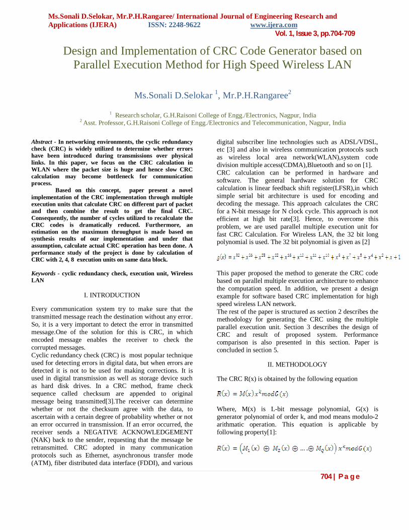
c) Simulation result for four parallel execution units :
Fig.7 Simulation result for four parallel execution unit
As per two execution units, simulation result for four parallel execution units, remainder A4568879 is got at 257th clock cycle.
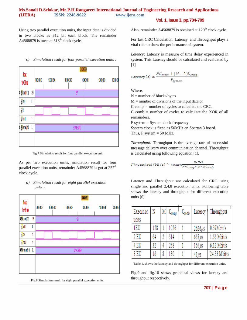
d) Simulation result for eight parallel execution units :
Fig.8 Simulation result for eight parallel execution units.
Also, remainder A4568879 is obtained at 129th clock cycle.
For fast CRC Calculation, Latency and Throughput plays a vital role to show the performance of system.
Latency: Latency is measure of time delay experienced in system. This Latency should be calculated and evaluated by [1]
Where, N = number of blocks/bytes. M = number of divisions of the input data.or C comp = number of cycles to calculate the CRC. C comb = number of cycles to calculate the XOR of all remainders. F system = System clock frequency. System clock is fixed as 50MHz on Spartan 3 board. Thus, F system = 50 MHz.
Throughput: Throughput is the average rate of successful message delivery over communication channel. Throughput is calculated using following equation [1].
Latency and Throughput are calculated for CRC using single and parallel 2,4,8 execution units. Following table shows the latency and throughput for different execution units [6].
Table 1. shows the latency and throughput for different execution units.
Fig.9 and fig.10 shows graphical views for latency and throughput respectively.
Ms.Sonali D.Selokar, Mr.P.H.Rangaree/ International Journal of Engineering Research and Applications (IJERA) ISSN: 2248-9622 www.ijera.com Vol. 1, Issue 3, pp.704-709
708 | P a g e
Fig.9 show latency for different execution units
From latency, it is cleared that as number of execution units increases, latency is decreases and for multiple parallel execution units have low latency as compared to serial execution unit.
Fig.10 shows throughput for different execution units From throughput, it shows that throughput is increases as number of execution units increases and parallel multiple execution units have more throughput than serial single execution unit. The Designed fast CRC based on multiple execution units are targeted to xilinx FPGA. The synthesis report for this as under.Table 2 shows utilization of FPGA resources.
TABLE2. RESOURCE UTILIZATION REPORT FOR CRC
GENERATOR FOR SPARTAN3 FPGA
V.CONCLUSION
The fast CRC generator using parallel multiple execution units has been designed and result are verified. The performance comparision of fast CRC using single execution unit and 2,4, 8 execution units are obtained in term of latency and throughput and resources utilization. It is concluded that for fast CRC, as number of multiple parallel execution units increases, the latency is decreases and it is very beneficial for error detection during data transmission.
REFERENCES [1] S.-R. Yoon, S. Seo, M.L. Huang and S.-C. Park : Multi-processor based CRC computation scheme for high-speed wireless LAN design. IEEE ELECTRONICS LETTERS 27th May 2010 Vol. 46 No. 11.
[2] Tomas Henriksson and Dake Liu:Implementation of Fast CRC Calculation 2003 IEEE.
[3] H. Michael Ji, and Earl Killian: Fast Parallel CRC Algorithm and Implementation on a Configurable Processor. 2002 IEEE.
[4]Sanjay M. Joshi, Pradeep K. Dubey, Marc A. Kaplan: A New Parallel Algorithm for CRC Generation. 2002 IEEE.
Ms.Sonali D.Selokar, Mr.P.H.Rangaree/ International Journal of Engineering Research and Applications (IJERA) ISSN: 2248-9622 www.ijera.com Vol. 1, Issue 3, pp.704-709