International Journal of Electrical and Electronics Research ISSN 2348-6988 (online) Vol. 7, Issue 2, pp: (1-20), Month: April - June 2019, Available at: www.researchpublish.com Page | 1 Research Publish Journals DESIGN AND IMPLEMENTATION OF IOT BASED ELECTRICITY METERING SYSTEM Dr. G. P. Ramesh 1 , Ranjudha 2 , Ajay Krishnan S M 3 , Manoj Kumar M 4 , Gangaraju Kumar 5 , Bharath N 6 1 Head of Department (ECE), 2 Assistant Professor (ECE), 3456 UG Scholar (ECE) St. Peter‟s Institute of Higher Education and Research, Chennai, India Abstract: Energy meter or watt-hour meter or is an electrical instrument that measures the amount of electrical energy used by the consumers. Utilities is one of the electrical departments, which install these instruments at every place like homes, industries, organizations, commercial buildings to charge for the electricity consumption by loads such as lights, fans, refrigerator and other home appliances. In our system we allow the electricity department to read the meter readings monthly without a person visiting each house. It utilizes the features of embedded systems and IoT (Internet of Things) to implement the desired functionality. We have also interfaced power tripping system which will trip the power in case of over voltage or fire detection and also when there are dues in the electricity bills. We also monitor the usage online every day and using analytics we compare the usage and take necessary steps to overcome heavy usage of electricity and to implement the bill payment method. Thus, we provide both client as well as customer side benefits as a solution to the electricity department. This project is suitable for all the types of energy meters, digital or analog and also provides flexible conversion between Post- paid and Pre-paid. It is also inbuilt with temperature sensors to notify the fire accidents to the relevant departments and to shut down the power automatically in such cases. Keywords: Internet of Things, Electricity Meter Reading, Power Supply Management, Electricity Bill Generation. I. INTRODUCTION IoT is a major technology by which we can produce various useful internet applications. Basically, IoT is a network in which all physical objects are connected to the internet through network devices or routers and exchange data. IoT allows objects to be controlled remotely across existing network infrastructure. IoT is a very good and intelligent technique which reduces human effort as well as easy access to physical devices. This technique also has autonomous control feature by which any device can control without any human interaction. “Things” in the IoT sense, is the mixture of hardware, software, data, and services. “Things” can refer to a wide variety of devices such as DNA analysis devices for environmental monitoring, electric clamps in coastal waters, Arduino chips in home automation and many other. These devices gather useful data with the help of various existing technologies and share that data between other devices. Examples include Home Automation System which uses Wi-Fi or Bluetooth for exchange data between various devices of home. When we look at today‟s state of technologies, we get a clear indication of how IoT will be implemented on a global level in near future. Use of the internet is increasing day-by-day. Commute and connectivity became easier in the present scenario. In near future, the number of internet connected devices would increase exponentially. With such a rapid growth of IoT Technology, the day is not too far that we can decide our dinner even before reaching home on the way. In the present billing system the distribution companies are unable to keep track of the changing maximum demand of consumers. The consumer is facing problems like receiving due bills for bills that have already been paid as well as poor reliability of electricity supply and quality even if bills are paid regularly. The remedy for all these problems is to keep track of the consumers load on timely basis, which will held to assure accurate billing, track maximum demand and to detect threshold value. These are all the features to be taken into account for designing an efficient energy billing system.
Transcript
International Journal of Electrical and Electronics Research ISSN 2348-6988 (online) Vol. 7, Issue 2, pp: (1-20), Month: April - June 2019, Available at: www.researchpublish.com
Page | 1 Research Publish Journals
DESIGN AND IMPLEMENTATION OF IOT
BASED ELECTRICITY METERING
SYSTEM
Dr. G. P. Ramesh1, Ranjudha
2, Ajay Krishnan S M
3, Manoj Kumar M
4,
Gangaraju Kumar5, Bharath N
6
1Head of Department (ECE),
2Assistant Professor (ECE),
3456UG Scholar (ECE)
St. Peter‟s Institute of Higher Education and Research, Chennai, India
Abstract: Energy meter or watt-hour meter or is an electrical instrument that measures the amount of electrical
energy used by the consumers. Utilities is one of the electrical departments, which install these instruments at
every place like homes, industries, organizations, commercial buildings to charge for the electricity consumption
by loads such as lights, fans, refrigerator and other home appliances. In our system we allow the electricity
department to read the meter readings monthly without a person visiting each house. It utilizes the features of
embedded systems and IoT (Internet of Things) to implement the desired functionality. We have also interfaced
power tripping system which will trip the power in case of over voltage or fire detection and also when there are
dues in the electricity bills. We also monitor the usage online every day and using analytics we compare the usage
and take necessary steps to overcome heavy usage of electricity and to implement the bill payment method. Thus,
we provide both client as well as customer side benefits as a solution to the electricity department. This project is
suitable for all the types of energy meters, digital or analog and also provides flexible conversion between Post-
paid and Pre-paid. It is also inbuilt with temperature sensors to notify the fire accidents to the relevant
departments and to shut down the power automatically in such cases.
Keywords: Internet of Things, Electricity Meter Reading, Power Supply Management, Electricity Bill Generation.
I. INTRODUCTION
IoT is a major technology by which we can produce various useful internet applications. Basically, IoT is a network in
which all physical objects are connected to the internet through network devices or routers and exchange data. IoT allows
objects to be controlled remotely across existing network infrastructure. IoT is a very good and intelligent technique
which reduces human effort as well as easy access to physical devices. This technique also has autonomous control
feature by which any device can control without any human interaction. “Things” in the IoT sense, is the mixture of
hardware, software, data, and services. “Things” can refer to a wide variety of devices such as DNA analysis devices for
environmental monitoring, electric clamps in coastal waters, Arduino chips in home automation and many other. These
devices gather useful data with the help of various existing technologies and share that data between other devices.
Examples include Home Automation System which uses Wi-Fi or Bluetooth for exchange data between various devices
of home. When we look at today‟s state of technologies, we get a clear indication of how IoT will be implemented on a
global level in near future. Use of the internet is increasing day-by-day. Commute and connectivity became easier in the
present scenario. In near future, the number of internet connected devices would increase exponentially. With such a rapid
growth of IoT Technology, the day is not too far that we can decide our dinner even before reaching home on the way.
In the present billing system the distribution companies are unable to keep track of the changing maximum demand of
consumers. The consumer is facing problems like receiving due bills for bills that have already been paid as well as poor
reliability of electricity supply and quality even if bills are paid regularly. The remedy for all these problems is to keep
track of the consumers load on timely basis, which will held to assure accurate billing, track maximum demand and to
detect threshold value. These are all the features to be taken into account for designing an efficient energy billing system.
International Journal of Electrical and Electronics Research ISSN 2348-6988 (online) Vol. 7, Issue 2, pp: (1-20), Month: April - June 2019, Available at: www.researchpublish.com
Page | 2 Research Publish Journals
The proposed project addresses the problems faced by both the consumers and the distribution companies. The paper
mainly deals with smart energy meter, which utilizes the features of embedded systems i.e. combination of hardware and
software in order to implement desired functionality. The paper discusses comparison of IoT Technology and other
controllers to introduce „Smart‟ concept. With the use of IoT device, the consumer as well as service provider will get the
used energy reading with the respective amount, Consumers will even get notification when they reach their bill
generation date. Also, the consumer can monitor his consumed reading and can set the threshold value through webpage.
This system enables the electricity department to read the meter readings monthly without a person visiting each house.
This can be achieved using Micro-Controller unit that continuously monitor and records the energy meter reading in its
permanent (non-volatile) memory location and updates it to the desired web server. This system continuously records the
reading and the live meter reading can be displayed on webpage to the consumer on request. This system also can be used
for both post-paid and Pre-paid connection types and can be used to disconnect the power supply of the house when
needed. It also has an inbuilt temperature sensor unit in order to detect the fire accidents and shut down the power.
II. EXISTING SYSTEM AND PROPOSED SYSTEM
The present system in electricity meter reading is very complicated and involves huge human resource deployed to visit
the electricity meters physically to note the readings. Also, there is no special system to monitor the live monitoring of the
usage of electricity. Moreover, the present billing system is purely Post-paid, which results in large number of payment
dues making the department to move in loss. There is no special system to trip the supply of electricity during fire
accidents.
In the proposed system we allow the electricity department to read the meter readings monthly without a person visiting
each house. We have also interfaced power tripping system which will trip the power in case of over voltage or fire
detection. We also monitor the usage online every day and using analytics we compare the usage and take necessary steps
to overcome heavy usage of electricity and also implement the bill payment method. Thus we provide both client as well
as customer side benefits as a solution to the EB department.
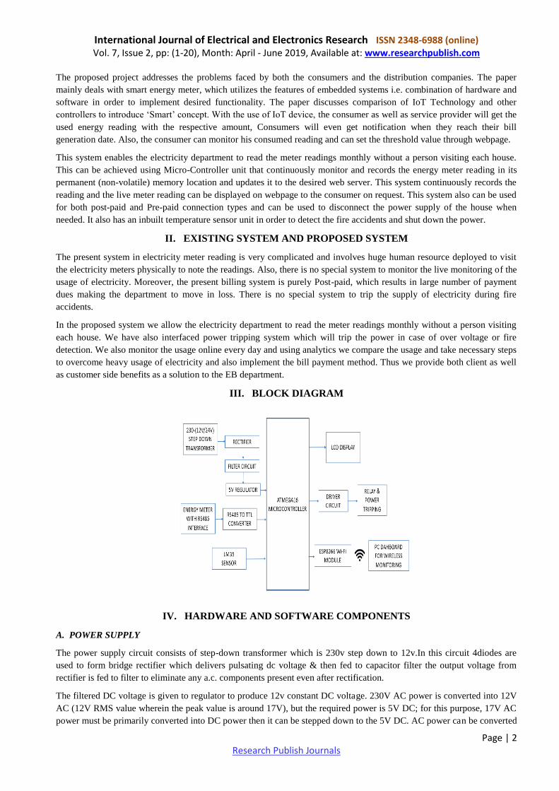
III. BLOCK DIAGRAM
IV. HARDWARE AND SOFTWARE COMPONENTS
A. POWER SUPPLY
The power supply circuit consists of step-down transformer which is 230v step down to 12v.In this circuit 4diodes are
used to form bridge rectifier which delivers pulsating dc voltage & then fed to capacitor filter the output voltage from
rectifier is fed to filter to eliminate any a.c. components present even after rectification.
The filtered DC voltage is given to regulator to produce 12v constant DC voltage. 230V AC power is converted into 12V
AC (12V RMS value wherein the peak value is around 17V), but the required power is 5V DC; for this purpose, 17V AC
power must be primarily converted into DC power then it can be stepped down to the 5V DC. AC power can be converted
International Journal of Electrical and Electronics Research ISSN 2348-6988 (online) Vol. 7, Issue 2, pp: (1-20), Month: April - June 2019, Available at: www.researchpublish.com
Page | 3 Research Publish Journals
into DC using one of the power electronic converters called as Rectifier. There are different types of rectifiers, such as
half-wave rectifier, full-wave rectifier and bridge rectifier. Due to the advantages of the bridge rectifier over the half and
full wave rectifier, the bridge rectifier is frequently used for converting AC to DC.
The following fig shows the circuit of a power supply that converts an ac source to a dc source
Power Supply Circuit
B. TRANSFORMER
Transformer is static device which transfer electrical energy from on circuit to other circuit with change i n voltage or
current without change in frequency. In this step down transformer is used. Usually, DC voltage s are require d to operate
various electronic equipment and these voltages are 5V, 9V or 12V. But these voltages cannot be obtained directly. Thus
the a.c input available at the mains supply i.e., 230V is to be brought own the required voltage level. This is done by a
transformer. Principle of transformer is according to Faraday's law o electromagnetic induction. An electrical transformer
works on the principle of Mutual Induction, which states that a uniform change in current in a coil will induce an E.M.F in
the other coil which is inductively coupled to the first coil.
In its basic form, a transformer consists of two coils with high mutual inductance that are electrically separated but have
common magnetic circuit. The following image shows the basic construction of a Transformer. The first set of the coil,
which is called as the Primary Coil or Primary Winding, is connected to an alternating voltage source called Primary
Voltage. The other coil, which is called as Secondary Coil or Secondary Winding, is connected to the load and the load
draws the resulting alternating voltage (stepped up or stepped down voltage).
The alternating voltage at the input excites the Primary Winding, an alternating current circulates the winding. The
alternating current will result in an alternating magnetic flux, which passes through the iron magnetic core and completes
its path. Since the secondary winding is also linked to the alternating magnetic flux, according to Faraday‟s Law, an
E.M.F is induced in the secondary winding. The strength of the voltage at the secondary winding is dependent on the
number of windings through which the flux gets passed through. Thus, without making an electrical contact, the
alternating voltage in the primary winding is transferred to the secondary winding.
Step-Down Transformer
\
International Journal of Electrical and Electronics Research ISSN 2348-6988 (online) Vol. 7, Issue 2, pp: (1-20), Month: April - June 2019, Available at: www.researchpublish.com
Page | 4 Research Publish Journals
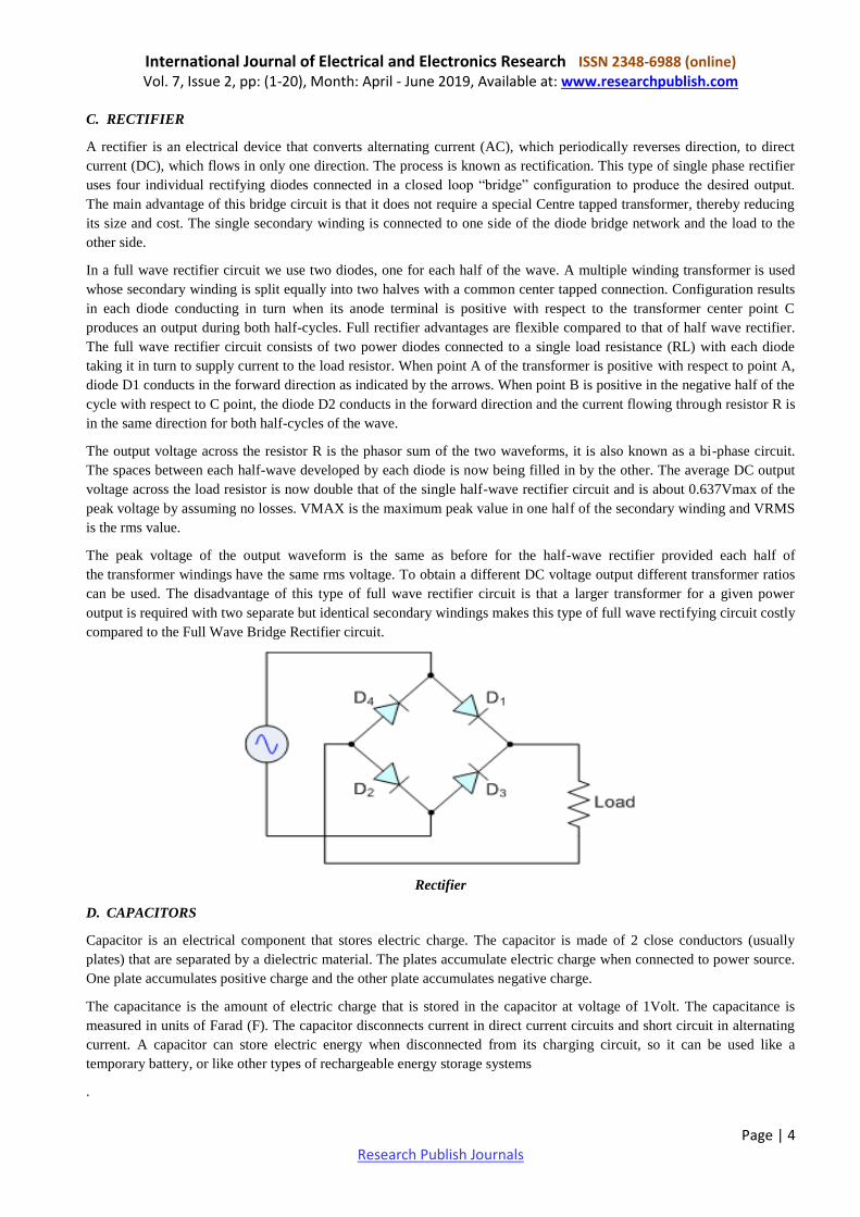
C. RECTIFIER
A rectifier is an electrical device that converts alternating current (AC), which periodically reverses direction, to direct
current (DC), which flows in only one direction. The process is known as rectification. This type of single phase rectifier
uses four individual rectifying diodes connected in a closed loop “bridge” configuration to produce the desired output.
The main advantage of this bridge circuit is that it does not require a special Centre tapped transformer, thereby reducing
its size and cost. The single secondary winding is connected to one side of the diode bridge network and the load to the
other side.
In a full wave rectifier circuit we use two diodes, one for each half of the wave. A multiple winding transformer is used
whose secondary winding is split equally into two halves with a common center tapped connection. Configuration results
in each diode conducting in turn when its anode terminal is positive with respect to the transformer center point C
produces an output during both half-cycles. Full rectifier advantages are flexible compared to that of half wave rectifier.
The full wave rectifier circuit consists of two power diodes connected to a single load resistance (RL) with each diode
taking it in turn to supply current to the load resistor. When point A of the transformer is positive with respect to point A,
diode D1 conducts in the forward direction as indicated by the arrows. When point B is positive in the negative half of the
cycle with respect to C point, the diode D2 conducts in the forward direction and the current flowing through resistor R is
in the same direction for both half-cycles of the wave.
The output voltage across the resistor R is the phasor sum of the two waveforms, it is also known as a bi-phase circuit.
The spaces between each half-wave developed by each diode is now being filled in by the other. The average DC output
voltage across the load resistor is now double that of the single half-wave rectifier circuit and is about 0.637Vmax of the
peak voltage by assuming no losses. VMAX is the maximum peak value in one half of the secondary winding and VRMS
is the rms value.
The peak voltage of the output waveform is the same as before for the half-wave rectifier provided each half of
the transformer windings have the same rms voltage. To obtain a different DC voltage output different transformer ratios
can be used. The disadvantage of this type of full wave rectifier circuit is that a larger transformer for a given power
output is required with two separate but identical secondary windings makes this type of full wave rectifying circuit costly
compared to the Full Wave Bridge Rectifier circuit.
Rectifier
D. CAPACITORS
Capacitor is an electrical component that stores electric charge. The capacitor is made of 2 close conductors (usually
plates) that are separated by a dielectric material. The plates accumulate electric charge when connected to power source.
One plate accumulates positive charge and the other plate accumulates negative charge.
The capacitance is the amount of electric charge that is stored in the capacitor at voltage of 1Volt. The capacitance is
measured in units of Farad (F). The capacitor disconnects current in direct current circuits and short circuit in alternating
current. A capacitor can store electric energy when disconnected from its charging circuit, so it can be used like a
temporary battery, or like other types of rechargeable energy storage systems
.
International Journal of Electrical and Electronics Research ISSN 2348-6988 (online) Vol. 7, Issue 2, pp: (1-20), Month: April - June 2019, Available at: www.researchpublish.com
Page | 5 Research Publish Journals
Capacitors
E. RESISTORS
A resistor is an electrical component that limits or regulates the flow of electrical current in an electronic circuit. Resistors
can also be used to provide a specific voltage for an active device such as a transistor. All other factors being equal, in a
direct-current (DC) circuit, the current through a resistor is inversely proportional to its resistance, and directly
proportional to the voltage across it. This is the well-known Ohm's Law. In alternating-current (AC) circuits, this rule also
applies as long as the resistor does not contain inductance or capacitance.
Resistors can be fabricated in a variety of ways. The most common type in electronic devices and systems is the carbon-
composition resistor. Fine granulated carbon (graphite) is mixed with clay and hardened. The resistance depends on the
proportion of carbon to clay; the higher this ratio, the lower the resistance. Another type of resistor is made from winding
Nichrome or similar wire on an insulating form. This component, called a wire wound resistor, is able to handle higher
currents than a carbon-composition resistor of the same physical size. However, because the wire is wound into a coil, the
component acts as an inductors as well as exhibiting resistance. This does not affect performance in DC circuits, but can
have an adverse effect in AC circuits because inductance renders the device sensitive to changes in frequency.
Resistors
F. VOLTAGE REGULATOR
The 78xx (sometimes L78xx, LM78xx, MC78xx...) is a family of self-contained fixed linear voltage regulator integrated
circuits. The 78xx family is commonly used in electronic circuits requiring a regulated power supply due to their ease-of-
use and low cost. For ICs within the family, the xx is replaced with two digits, indicating the output voltage (for example,
the 7805 has a 5-volt output, while the 7812 produces 12 volts). The 78xx line are positive voltage regulators: they
produce a voltage that is positive relative to a common ground. There is a related line of 79xx devices which are
complementary negative voltage regulators. 78xx and 79xx ICs can be used in combination to provide positive and
negative supply voltages in the same circuit.
78xx ICs have three terminals and are commonly found in the TO-220 form factor, although they are available in surface-
mount, TO-92, andTO-3 packages. These devices support an input voltage anywhere from around 2.5 volts over the
intended output voltage up to a maximum of 35 to 40 volts depending on the model, and typically provide 1 or
1.5 amperes of current (though smaller or larger packages may have a lower or higher current rating).
International Journal of Electrical and Electronics Research ISSN 2348-6988 (online) Vol. 7, Issue 2, pp: (1-20), Month: April - June 2019, Available at: www.researchpublish.com
This series of fixed-voltage integrated-circuit voltage regulators is designed for a wide range of applications. These
applications include on-card regulation for elimination of noise and distribution problems associated with single-point
regulation. Each of these regulators can deliver up to 1.5 A of output current. The internal current-limiting and thermal-
shutdown features of these regulators essentially make them immune to overload. In addition to use as fixed-voltage
regulators, these devices can be used with external components to obtain adjustable output voltages and currents, and also
can be used as the power-pass element in precision regulators.
Reverse-Bias Protection:
Occasionally, the input voltage to the regulator can collapse faster than the output voltage. This can occur, for example,
when the input supply is crow barred during an output overvoltage condition. If the output voltage is greater than
approximately 7 V, the emitter-base junction of the series-pass element (internal or external) could break down and be
damaged.
G. TRANSISTOR DRIVER CIRCUIT
A transistor is a semiconductor device used to amplify or switch electronic signals and electrical power. It is composed
of semiconductor material with at least three terminals for connection to an external circuit. A voltage or current applied
to one pair of the transistor's terminals changes the current through another pair of terminals. Because the controlled
(output) power can be higher than the controlling (input) power, a transistor can amplify a signal. Today, some transistors
are packaged individually, but many more are found embedded in integrated circuits.
The transistor is the fundamental building block of modern electronic devices, and is ubiquitous in modern electronic
systems. First conceived by Julius Lilienfeld in 1926 and practically implemented in 1947 by American physicists John
Bardeen, Walter Brattain, and William Shockley, the transistor revolutionized the field of electronics, and paved the way
for smaller and cheaper radios, calculators, and computers, among other things. The transistor is on the list of IEEE
milestones in electronics, and Bardeen, Brattain, and Shockley shared the 1956 Nobel Prize in Physics for their
achievement.
The transistor's low cost, flexibility, and reliability have made it a ubiquitous device. Transistorized mechatronic circuits
have replaced electromechanical devices in controlling appliances and machinery. It is often easier and cheaper to use a
standard microcontroller and write a computer program to carry out a control function than to design an equivalent
mechanical control function.
International Journal of Electrical and Electronics Research ISSN 2348-6988 (online) Vol. 7, Issue 2, pp: (1-20), Month: April - June 2019, Available at: www.researchpublish.com
Page | 7 Research Publish Journals
Transistor
H. AVR MICRO-CONTROLLER
AVR is a family of microcontrollers developed by Atmel beginning in 1996. These are modified Harvard architecture 8-
bit RISC single-chip microcontrollers. AVR was one of the first microcontroller families to use on-chip flash memory for
program storage, as opposed to one-time programmable ROM, EPROM, or EEPROM used by other microcontrollers at
the time.
The AVR architecture was conceived by two students at the Norwegian Institute of Technology (NTH), Alf-Egil
Bogen and Vegard Wollan.
The original AVR MCU was developed at a local ASIC house in Trondheim, Norway, called Nordic VLSI at the time,
now Nordic Semiconductor, where Bogen and Wollan were working as students. It was known as a μRISC (Micro RISC[
and was available as silicon IP/building block from Nordic VLSI. When the technology was sold to Atmel from Nordic
VLSI, the internal architecture was further developed by Bogen and Wollan at Atmel Norway, a subsidiary of Atmel. The
designers worked closely with compiler writers at IAR Systems to ensure that the AVR instruction set provided
efficient compilation of high-level languages
Atmel says that the name AVR is not an acronym and does not stand for anything in particular. The creators of the AVR
give no definitive answer as to what the term "AVR" stands for However, it is commonly accepted that AVR stands
for Alf and Vegard's RISC processor, Note that the use of "AVR" in this article generally refers to the 8-bit RISC line of
Atmel AVR Microcontrollers.
Among the first of the AVR line was the AT90S8515, which in a 40-pin DIP package has the same pin out as
an 8051 microcontroller, including the external multiplexed address and data bus.
The fig shows the pin diagram of the controller used
PIN Diagram of AVR Micro-Controller
International Journal of Electrical and Electronics Research ISSN 2348-6988 (online) Vol. 7, Issue 2, pp: (1-20), Month: April - June 2019, Available at: www.researchpublish.com
Page | 8 Research Publish Journals
I. ENERGY METER (DZS100-1P)
DZS100-1P is a compact single-phase energy meter, integrating measuring, metering, LCD display and communication in
one. It meters electric parameters of energy, voltage, current, power, power factor etc. Equipped with RS485
communication interfaces, it supports both DL/T645-2007 and Modbus RTU protocol.
Physical performance of DZS100-1P complies with national standard of GB/TI7215.3212008 and all required standards
of energy meters carried out by Electric Power Industry Standard DL/T614/2007.
With high-precision metering IC and high-speed MCU data processing unit, the highaccuracy wide-range accurate
measurement can be realized. It is possessed with advantages of LCD display, high reliability, high overload, strong
stability, low consumption, data saved automatically power-off. Besides, the data can be exchanged between RS485
communication interface and upper computer. What‟s more, small size, high accuracy and easy installation are also its
advantages. With standard 35mm Din-rail installation, the meter can be installed in distribution cabinet and small
distribution box. It is suitable for submetering in single device, school dormitories, tenants and large public buildings etc.
It can also be used for energy management examination in enterprises and public institutions.
Digital Electricity Meter
Specification
Reference Voltage: 220V
Current Specification: 5(40)A, 10(60)A
Pulse Constant: 1600imp/kWh, 800 imp/kWh
Frequency: 45~60Hz (the default is 50Hz)
Accuracy Class: Class 1.0
Electricity Parameters
Voltage Consumption in Circuit: <2W, 10VA
Current Consumption in Circuit: <1VA
Voltage Range: Normal Range: 0.9-1.1Un
Limit Range: 0.7-1.2Un
J. RS 485 TO TTL MODULE
RS485 is another protocol supported by the primary serial port on the QVGA Controller. It is a protocol, meaning that
only one party at a time may transmit data. Unlike the standard RS232 protocol, RS485 allows many communicating
parties to share the same 3-wire communications cable. Thus RS485 is the standard protocol of choice
when communications are required.Like RS232, the data bits are transmitted in reverse order, with the least significant bit
transmitted first. The RS485 protocol uses differential data signals for improved noise immunity; thus RS485 can
communicate over greater distances than RS232. An RS485 transceiver is present on the QVGA Controller, and its data
direction is controlled by pin 4 of port PPC of the peripheral interface adapter (PIA).
International Journal of Electrical and Electronics Research ISSN 2348-6988 (online) Vol. 7, Issue 2, pp: (1-20), Month: April - June 2019, Available at: www.researchpublish.com
Page | 9 Research Publish Journals
RS485 Module is the most flexible communication module in the standard series of definition by EIA. RS485 has various
features which include:
Connection of DTE's directly without modems
Connection of several DTE's within a network
Capability of communicating over larger distances
Capability of communicating at faster rates
RS485 TO TTL Module
RS485 to TTL Module shown in the Figure generally fulfils the needs required for a multi-point communications network
which is popular nowadays. The standard specification of RS485 is that it can connect up to 32 drivers which is known as
transmitters and 32 receivers with the help of a single (two wire) bus which is capable of establishing connection over
4000 feet. With the evolvement of the automatic repeaters and that of high impedance possessing drivers and receivers the
limitation of 4000 feet can be extended up to hundreds or even thousands of connectable nodes on a single network over a
distance of about 1200 meters. It also helps in extending the common mode range for both transmitters as well as
receivers basically in the tri-state mode and with a power off condition. RS485 transmitters (drivers) are capable of
withstanding data collision problems as well as bus mistakes.
K. RELAY
A relay is an electrically operated switch. Many relays use an electromagnet to mechanically operate a switch, but other
operating principles are also used, such as solid-state relays. Relays are used where it is necessary to control a circuit by a
separate low-power signal, or where several circuits must be controlled by one signal. The first relays were used in long
distance telegraph circuits as amplifiers: they repeated the signal coming in from one circuit and re-transmitted it on
another circuit. Relays were used extensively in telephone exchanges and early computers to perform logical operations.
The fig.shows the image of a relay.
RELAY
A type of relay that can handle the high power required to directly control an electric motor or other loads is called
a contactor. Solid-state relays control power circuits with no moving parts, instead using a semiconductor device to
perform switching. Relays with calibrated operating characteristics and sometimes multiple operating coils are used to
protect electrical circuits from overload or faults; in modern electric power systems these functions are performed by
digital instruments still called "protective relays".
International Journal of Electrical and Electronics Research ISSN 2348-6988 (online) Vol. 7, Issue 2, pp: (1-20), Month: April - June 2019, Available at: www.researchpublish.com
Page | 10 Research Publish Journals
Magnetic latching relays require one pulse of coil power to move their contacts in one direction, and another, redirected
pulse to move them back. Repeated pulses from the same input have no effect. Magnetic latching relays are useful in
applications where interrupted power should not be able to transition the contacts.
Magnetic latching relays can have either single or dual coils. On a single coil device, the relay will operate in one
direction when power is applied with one polarity, and will reset when the polarity is reversed. On a dual coil device,
when polarized voltage is applied to the reset coil the contacts will transition. AC controlled magnetic latch relays have
single coils that employ steering diodes to differentiate between operate and reset commands. A simple electromagnetic
relay consists of a coil of wire wrapped around a soft iron core, an iron yoke which provides a low reluctance path for
magnetic flux, a movable iron armature, and one or more sets of contacts (there are two contacts in the relay pictured).
The armature is hinged to the yoke and mechanically linked to one or more sets of moving contacts. The armature is held
in place by a spring so that when the relay is de-energized there is an air gap in the magnetic circuit. In this condition, one
of the two sets of contacts in the relay pictured is closed, and the other set is open. Other relays may have more or fewer
sets of contacts depending on their function. The relay in the picture also has a wire connecting the armature to the yoke.
This ensures continuity of the circuit between the moving contacts on the armature, and the circuit track on the printed
circuit board (PCB) via the yoke, which is soldered to the PCB.
When an electric current is passed through the coil it generates a magnetic field that activates the armature, and the
consequent movement of the movable contact(s) either makes or breaks (depending upon construction) a connection with
a fixed contact. If the set of contacts was closed when the relay was de-energized, then the movement opens the contacts
and breaks the connection, and vice versa if the contacts were open. When the current to the coil is switched off, the
armature is returned by a force, approximately half as strong as the magnetic force, to its relaxed position. Usually this
force is provided by a spring, but gravity is also used commonly in industrial motor starters. Most relays are manufactured
to operate quickly. In a low-voltage application this reduces noise; in a high voltage or current application it
reduces arcing.
When the coil is energized with direct current, a diode is often placed across the coil to dissipate the energy from the
collapsing magnetic field at deactivation, which would otherwise generate a voltage spike dangerous
to semiconductor circuit components. Such diodes were not widely used before the application of transistors as relay
drivers, but soon became ubiquitous as early germanium transistors were easily destroyed by this surge. Some automotive
relays include a diode inside the relay case.
If the relay is driving a large, or especially a reactive load, there may be a similar problem of surge currents around the
relay output contacts. In this case a snubbed circuit (a capacitor and resistor in series) across the contacts may absorb the
surge. Suitably rated capacitors and the associated resistor are sold as a single packaged component for this commonplace
use.
If the coil is designed to be energized with alternating current (AC), some method is used to split the flux into two out-of-
phase components which add together, increasing the minimum pull on the armature during the AC cycle. Typically this
is done with a small copper "shading ring" crimped around a portion of the core that creates the delayed, out-of-phase
component, which holds the contacts during the zero crossings of the control voltage.
L. LCD DISPLAY
Liquid crystals are a phase of matter whose order is intermediate between that of a liquid and that of a crystal. The
molecules are typically rod shaped organic matters about 25 Angstroms in length and their ordering is a function of
temperature. The molecular orientation can be controlled with applied electric fields. LCD is made up of two sheets of
polarizing material with the liquid crystal solution between them. An electric current passed through the liquid causes the
crystals to align so that light cannot pass through them, which results in display of character as per the applied voltage in
its data lines. The driver is provided to drive the LCD. It stores the display data transferred from the microcontroller in the
internal display RAM and generates dot matrix liquid crystal driving signals. Each bit data of display RAM corresponds
to on/off state of a dot of a liquid crystal display.
LCD is used in widespread applications due to the following reasons:
• The declining prices of LCDs.
• The ability to display numbers, characters, and graphics.
International Journal of Electrical and Electronics Research ISSN 2348-6988 (online) Vol. 7, Issue 2, pp: (1-20), Month: April - June 2019, Available at: www.researchpublish.com
Page | 11 Research Publish Journals
• Incorporation of a refreshing controller into the LCD, thereby
• Relieving the CPU of the task of refreshing the LCD.
• Ease of programming for characters and graphics.
The fig shows the image of a 16x2 LCD display
LCD DISPLAY
A standard character LCD is probably the most widely used data Visualization component.
Character LCDs are available in various kinds of models.
• No. Of characters and line
• Color: Yellow, Green, Gray, Blue…
The Character LCD communicates with the microcontroller via 8 bit data bus.
The pin description for character LCD is given below.
VCC, GND AND V0 - While VCC and VSS provide +5V and ground, respectively;
V0 is used for controlling LCD contrast.
RS (Register Select) - If RS = 0, the instruction command code register is selected, allowing the user to send a command
such as clear display, cursor at home, etc.
• If RS = 1, the data register is selected, allowing the user to send data to be displayed on the LCD.
• RW (Read/Write) - RW allows the user to write information to the LCD or read information from it. RW=1 when
reading; RW=0 when writing.
• EN (Enable) - The LCD to latch information presented to its data pins uses the enable pin. When data is supplied to
data pins, a high to low pulse must be applied to this pin in order for the LCD to latch in the data present at the data pins.
• D0 – D7 - The 8-bit data pins, are used to send information to the LCD or read the contents of the LCD‟s internal
registers. To display letters and numbers, we send ASCII codes for the letters A-Z, a-z, and numbers 0-9 to these pins
while making RS = 1.
For working with the LCD, the jumpers JP44 has to be closed and the potentiometer R74 can be adjusted for contrast
variation.
M. ESP8266 MODULE
The ESP8266 is a low-cost Wi-Fi chip with full TCP/IP stack and MCU (microcontroller unit) capability produced by
Shanghai-based Chinese manufacturer, Espresso. The chip first came to the attention of western makers in August 2014
with the ESP-01 module, made by a third-party manufacturer, AI-Thinker. This small module allows microcontrollers to
connect to a Wi-Fi network and make simple TCP/IP connections using Hayes-style commands. However, at the time
there was almost no English-language documentation on the chip and the commands it accepted. The very low price and
the fact that there were very few external components on the module which suggested that it could eventually be very
inexpensive in volume, attracted many hackers to explore the module, chip, and the software on it, as well as to translate
the Chinese documentation. The ESP8285 is an ESP8266 with 1 MiB of built-in flash, allowing for single-chip devices
capable of connecting to Wi-Fi.
International Journal of Electrical and Electronics Research ISSN 2348-6988 (online) Vol. 7, Issue 2, pp: (1-20), Month: April - June 2019, Available at: www.researchpublish.com
Page | 12 Research Publish Journals
The successor to these microcontroller chips is the ESP32. ESP8266 (presently ESP8266EX) is a chip with which
manufacturers are making wirelessly networkable micro-controller modules. More specifically, ESP8266 is a system-on-
a-chip (SoC) with capabilities for 2.4 GHz Wi-Fi (802.11 b/g/n, supporting WPA/WPA2), general-purpose input/output
interfaces with DMA (sharing pins with GPIO), UART (on dedicated pins, plus a transmit-only UART can be enabled on
GPIO2), and pulse-width modulation (PWM). The processor core, called "L106" by Espressif, is based on Tensilica‟s
Diamond Standard 106Micro 32-bit processor controller core and runs at 80 MHz (or overclocked to 160 MHz). It has a
64 KB boot ROM, 64 KB instruction RAM and 96 KB data RAM. External flash memory can be accessed through SPI.
The fig shows the circuit diagram of how an ESP module is connected.
ESP Connection Circuit Diagram
N. LM 35 SENSOR
The LM35 is one kind of commonly used temperature sensor that can be used to measure temperature with an electrical
o/p comparative to the temperature (in °C). It can measure temperature more correctly compare with a thermistor. This
sensor generates a high output voltage than thermocouples and may not need that the output voltage is amplified. The
LM35 has an output voltage that is proportional to the Celsius temperature. The scale factor is .01V/°C. The fig shows the
image of an LM35 sensor.
LM35 Temperature Sensor
The LM35 does not need any exterior calibration and maintains an exactness of +/-0.4°C at room temperature and +/-
0.8°C over a range of 0°C to +100°C.One more significant characteristic of this sensor is that it draws just 60 microamps
from its supply and acquires a low self-heating capacity. The LM35 temperature sensor available in many different
packages like T0-46 metal can transistor-like package, TO-92 plastic transistor-like package, 8-lead surface mount SO-8
small outline package.
Applications Of LM35 Temperature Sensor
The applications of LM35 temperature sensor include the following
Measuring temperature of a particular environment and HVAC applications
Providing thermal shutdown for a conductor circuit
Checking Battery Temperature
International Journal of Electrical and Electronics Research ISSN 2348-6988 (online) Vol. 7, Issue 2, pp: (1-20), Month: April - June 2019, Available at: www.researchpublish.com
Page | 13 Research Publish Journals
O. SIMULATION IN PROTEUS SUITE SOFTWARE
The micro-controller simulation in Proteus works by applying either a hex file or a debug file to the microcontroller part
on the schematic. It is then co-simulated along with any analog and digital electronics connected to it. This enables its use
in a broad spectrum of project prototyping in areas such as motor control, temperature control and user interface design. It
also finds use in the general hobbyist community and, since no hardware is required, is convenient to use as a training or
teaching tool. Support is available for co-simulation of:
The simulation of the project that is been done in proteus simulation tool which shows our actual setup is shown in fig 5.1
Proposed Simulation Circuit Design Screenshot
P. WORKING IN CODE VISION AVR
The program is designed to run under the Windows 98, Me, NT 4, 2000, XP and Vista 32bit operating systems.
The C cross-compiler implements nearly all the elements of the ANSI C language, as allowed by the AVR architecture,
with some features added to take advantage of specificity of the AVR architecture and the embedded system needs.
The compiled COFF object files can be C source level debugged, with variable watching, using the Atmel AVR Studio
debugger.
The Integrated Development Environment (IDE) has built-in AVR Chip In-System Programmer software that enables the
automatically transfer of the program to the microcontroller chip after successful compilation/assembly. The In-System
Programmer software is designed to work in conjunction with the Atmel STK500, AVRISP, AVRISP MkII, AVR
Dragon, JTAGICE MkII, AVRProg (AVR910 application note), Kanda Systems STK200+, STK300, Dontronics DT006,
Vogel Elektronik VTEC-ISP, Futurlec JRAVR and MicroTronics' ATCPU, Mega2000 development boards.
International Journal of Electrical and Electronics Research ISSN 2348-6988 (online) Vol. 7, Issue 2, pp: (1-20), Month: April - June 2019, Available at: www.researchpublish.com
Page | 14 Research Publish Journals
For debugging embedded systems, which employ serial communication, the IDE has a built-in Terminal.
Besides the standard C libraries, the CodeVisionAVR C compiler has dedicated libraries for:
Alphanumeric LCD modules
Philips I2C bus
National Semiconductor LM75 Temperature Sensor
Philips PCF8563, PCF8583, Maxim/Dallas Semiconductor DS1302 and DS1307 Real Time Clocks
Maxim/Dallas Semiconductor 1 Wire protocol
Maxim/Dallas Semiconductor DS1820, DS18S20 and DS18B20 Temperature Sensors
Maxim/Dallas Semiconductor DS2430 and DS2433 EEPROMs
SPI
Power management
Delays
Gray code conversion.
CodeVisionAVR also contains the CodeWizardAVR Automatic Program Generator, that allows you to write, in a matter
of minutes, all the code needed for implementing the following functions:
External memory access setup
Chip reset source identification
Input/Output Port initialization
External Interrupts initialization
Timers/Counters initialization
Watchdog Timer initialization
UART (USART) initialization and interrupt driven buffered serial communication
Analog Comparator initialization
ADC initialization
SPI Interface initialization
Two Wire Interface initialization
CAN Interface initialization
I2C Bus, LM75 Temperature Sensor, DS1621 Thermometer/Thermostat and PCF8563, PCF8583, DS1302, DS1307
Real Time Clocks initialization
1 Wire Bus and DS1820/DS18S20 Temperature Sensors initialization
LCD module initialization.
International Journal of Electrical and Electronics Research ISSN 2348-6988 (online) Vol. 7, Issue 2, pp: (1-20), Month: April - June 2019, Available at: www.researchpublish.com
Page | 15 Research Publish Journals
Working with CodeVisionAVR
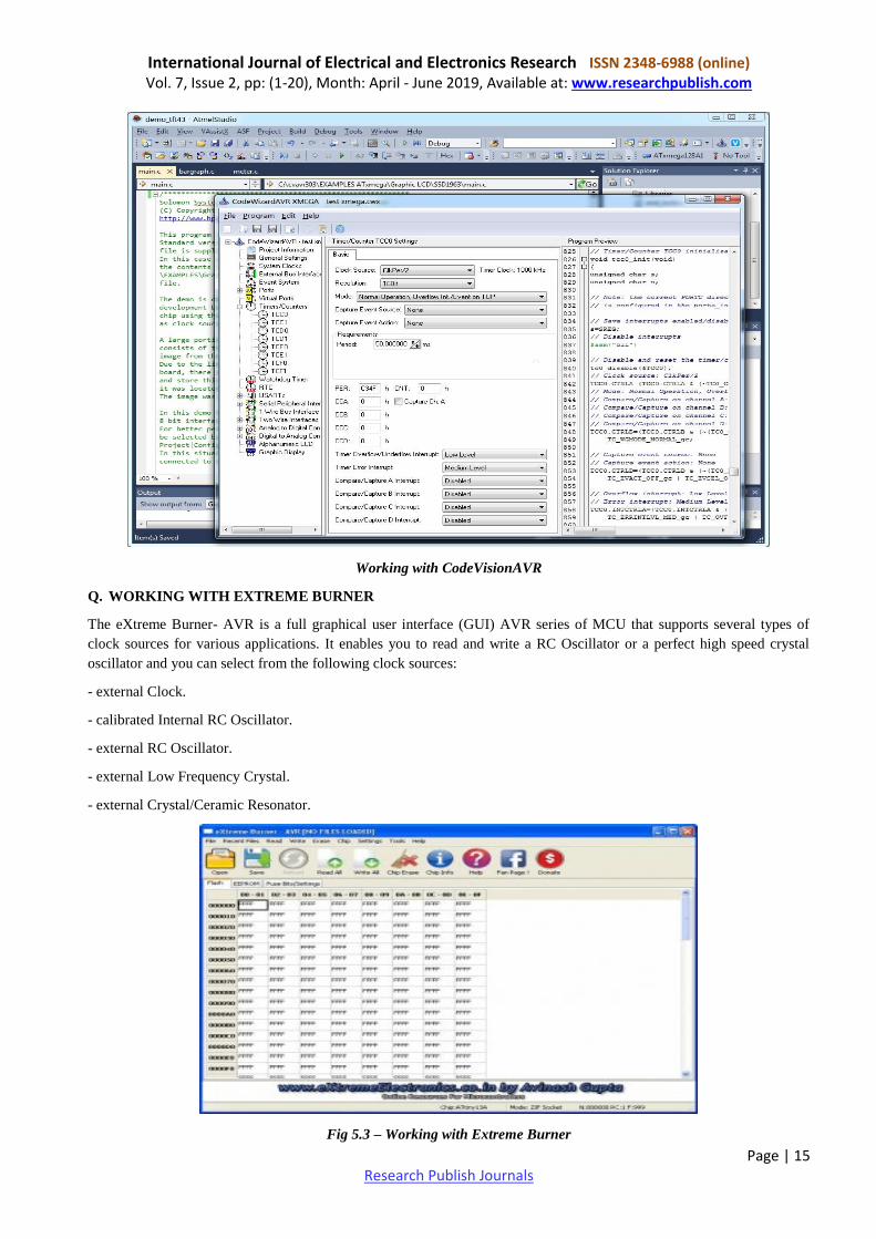
Q. WORKING WITH EXTREME BURNER
The eXtreme Burner- AVR is a full graphical user interface (GUI) AVR series of MCU that supports several types of
clock sources for various applications. It enables you to read and write a RC Oscillator or a perfect high speed crystal
oscillator and you can select from the following clock sources:
- external Clock.
- calibrated Internal RC Oscillator.
- external RC Oscillator.
- external Low Frequency Crystal.
- external Crystal/Ceramic Resonator.
Fig 5.3 – Working with Extreme Burner
International Journal of Electrical and Electronics Research ISSN 2348-6988 (online) Vol. 7, Issue 2, pp: (1-20), Month: April - June 2019, Available at: www.researchpublish.com
Page | 16 Research Publish Journals
R. NODE Js
Node.js allows the creation of Web servers and networking tools using JavaScript and a collection of "modules" that
handle various core functionality Modules are provided for file system I/O, networking (DNS, HTTP, TCP, TLS/
SSL,or UDP), binary data(buffers), cryptography functions, data streams, and other core functions Node.js's modules use
an API designed to reduce the complexity of writing server applications.
Node.js applications can run on Linux, macOS, Microsoft Windows, NonStop, and Unix servers. Alternatively, they can
be written with CoffeeScript (a JavaScript alternative), Dart or TypeScript (strongly typed forms of JavaScript), or any
other language that can compile to JavaScript.
Node.js is primarily used to build network programs such as Web servers. The biggest difference between Node.js
and PHP is that most functions in PHP block until completion (commands execute only after previous commands have
completed), while functions in Node.js are designed to be non-blocking (commands execute concurrently or even
in parallel, and use callbacks to signal completion or failure).
Fig 5.4 Parts of Node Js
Following are the areas where Node.js is proving itself as a perfect technology partner.
I/O bound Applications
Data Streaming Applications
Data Intensive Real-time Applications (DIRT)
JSON APIs based Applications
Single Page Applications
S. XAMPP
XAMPP (/ˈzæmp/ or /ˈ ɛks.æmp/) is a free and open source cross-platform web server solution stack package, consisting
mainly of the Apache HTTP Server, MySQL database, and interpreters for scripts written in the PHP and Perl
programming languages.
Etymology
• XAMPP's name is an acronym for:
• X (to be read as "cross", meaning crossplatform)
• Apache HTTP Server
• MySQL
• PHP
International Journal of Electrical and Electronics Research ISSN 2348-6988 (online) Vol. 7, Issue 2, pp: (1-20), Month: April - June 2019, Available at: www.researchpublish.com
Page | 17 Research Publish Journals
• Perl
• Tomcat
X(Cross platform)
• Cross-platform, or multi-platform, is an attribute conferred to computer software or computing methods and concepts
that are implemented and inter-operate on multiple computer platforms.
Apache HTTP Server
• It is a web server software program notable for playing a key role in the initial growth of the World Wide Web.
• According to the Frequently Asked Questions in the Apache project website, the name Apache was chosen out of
respect to the Native American tribe Apache and its superior skills in warfare and strategy.
• Virtual hosting allows one Apache installation to serve many different websites. For example, one machine with one
Apache installation could simultaneously serve www.example.com, www.example.org, test47. test-server.example.edu,
etc.
• It is a web server that allows you to host your websites or any other content for that matter. Apache is available for
UNIX as well as WINDOWS. Some of the most common server-side languages supported by Apache are - PHP, Python
and Perl. It is free of charge.
T. MySQL
• It is the world's most popular open source database. It is a Relational Database Management System (RDBMS) - data
and it's relationships are stored in the form of tables that can be accessed by the use of MySQL queries in almost any
format that the user wants.
• MySQL is a database system used on the web server
• MySQL is ideal for both small and large applications
• MySQL is very fast, reliable, and easy to use
• MySQL compiles on a number of platforms
• MySQL is free to download and use
• MySQL is developed, distributed, and supported by Oracle Corporation
• MySQL is named after co-founder Monty Widenius's daughter: My
U. VISUAL STUDIO
Visual Studio Code combines the simplicity of a source code editor with powerful developer tooling, like IntelliSense
code completion and debugging.
First and foremost, it is an editor that gets out of your way. The delightfully frictionless edit-build-debug cycle means less
time fiddling with your environment, and more time executing on your ideas.
Visual Studio Code supports macOS, Linux, and Windows - so you can hit the ground running, no matter the platform.
At its heart, Visual Studio Code features a lightning fast source code editor, perfect for day-to-day use. With support for
hundreds of languages, VS Code helps you be instantly productive with syntax highlighting, bracket-matching, auto-
indentation, box-selection, snippets, and more. Intuitive keyboard shortcuts, easy customization and community-
contributed keyboard shortcut mappings let you navigate your code with ease.
For serious coding, you'll often benefit from tools with more code understanding than just blocks of text. Visual Studio
Code includes built-in support for IntelliSense code completion, rich semantic code understanding and navigation, and
code refactoring.
And when the coding gets tough, the tough get debugging. Debugging is often the one feature that developers miss most
in a leaner coding experience, so we made it happen. Visual Studio Code includes an interactive debugger, so you can
step through source code, inspect variables, view call stacks, and execute commands in the console.
International Journal of Electrical and Electronics Research ISSN 2348-6988 (online) Vol. 7, Issue 2, pp: (1-20), Month: April - June 2019, Available at: www.researchpublish.com
Page | 18 Research Publish Journals
VS Code also integrates with build and scripting tools to perform common tasks making everyday workflows faster. VS
Code has support for Git so you can work with source control without leaving the editor including viewing pending
changes diffs.
Customize every feature to your liking and install any number of third-party extensions. While most scenarios work "out
of the box" with no configuration, VS Code also grows with you, and we encourage you to optimize your experience to
suit your unique needs. VS Code is an open source project so you can also contribute to the growing and vibrant
community on GitHub.
VS Code includes enriched built-in support for Node.js development with JavaScript and TypeScript, powered by the
same underlying technologies that drive Visual Studio. VS Code also includes great tooling for web technologies such as
JSX/React, HTML, CSS, SCSS, Less, and JSON.
Architecturally, Visual Studio Code combines the best of web, native, and language-specific technologies.
Using Electron, VS Code combines web technologies such as JavaScript and Node.js with the speed and flexibility of
native apps. VS Code uses a newer, faster version of the same industrial-strength HTML-based editor that has powered
the “Monaco” cloud editor, Internet Explorer's F12 Tools, and other projects. Additionally, VS Code uses a tools service
architecture that enables it to integrate with many of the same technologies that power Visual Studio, including Roslyn for
.NET, TypeScript, the Visual Studio debugging engine, and more.
Visual Studio Code includes a public extensibility model that lets developers build and use extensions, and richly
customize their edit-build-debug experience.
V. COMMON COMMUNICATION SETTINGS
Other common specifications for Modbus devices have to do with the serial communication protocol parameters. These
are common parameters that often need to be set by a user.
A. DEVICE ADDRESS/SLAVE ID
Usually programmable for 1 – 247 devices, each device on the Modbus network requires a unique address. This allows
devices on the network to know what data packets are relevant to them, and which are meant for other devices.
B. BAUD RATE
This is the communications speed in bits per second (bps). This must be identical for all devices on the network. This is
usually in the range of 300 - 19,200 bps.
C. DATA FORMAT
8 bit (1 start bit, 1 or 2 stop bits, etc.) The number of start bits, stop bits, etc. is used to configure the Modbus data packet.
This should match on all devices on the network.
D. PARITY
Even, odd, or none with 1 or 2 stop bits) Like the data format, this relates to the Modbus data pack configuration. It
should match on all devices on the network.
Many other possible serial communications parameters may be set by a user in a Modbus device. Byte-to-byte timeouts,
transmit delays, and other settings are often available, but the default settings are often sufficient for simple networks.
E. SERIAL TRANSMISSION MODES OF MODBUS NETWORK
The transmission mode defines the bit contents of the message bytes transmitted along the network, and how the message
information is to be packed into the message stream and decoded. Standard MODBUS networks employ one of two types
of transmission modes: 4.1. ASCII Mode 4.2. RTU Mode. The mode of transmission is usually selected along with other
serial port communication parameters (baud rate, parity, etc.) as part of the device configuration. Technical Tutorial
Introduction to MODBUS.
F. ASCII TRANSMISSION MODE
In the ASCII Transmission Mode (American Standard Code for Information Interchange), each character byte in a
message is sent as 2 ASCII characters. This mode allows time intervals of up to a second between characters during
transmission without generating errors.
International Journal of Electrical and Electronics Research ISSN 2348-6988 (online) Vol. 7, Issue 2, pp: (1-20), Month: April - June 2019, Available at: www.researchpublish.com
Page | 19 Research Publish Journals
G. RTU (REMOTE TERMINAL UNIT) TRANSMISSION MODE
In RTU (Remote Terminal Unit) Mode, each 8-bit message byte contains two 4-bit hexadecimal characters, and the
message is transmitted in a continuous stream. The greater effective character density increases throughput over ASCII
mode at the same baud rate.
H. MODBUS MESSAGE FRAMING
A message frame is used to mark the beginning and ending point of a message allowing the receiving device to determine
which device is being addressed and to know when the message is completed. It also allows partial messages to be
detected and errors flagged as a result. .
I. MODBUS ADDRESSES
The master device addresses a specific slave device by placing the 8-bit slave address in the address field of the message
(RTU Mode). The address field of the message frame contains two characters (in ASCII mode), or 8 binary bits (in RTU
Mode). Valid addresses are from 1-247. When the slave responds, it places its own address in this field of its response to
let the master know which slave is responding The address field of the message frame contains two characters (in ASCII
mode), or 8 binary bits (in RTU Mode). Valid addresses are from 1-247. placing the 8-bit slave address in the address
field of the message RTU Mode 8 binary bits in RTU Mode of modbus addresses.
J. MODBUS FUNCTIONS
The function code field of the message frame will contain two characters (in ASCII mode), or 8 binary bits (in RTU
Mode) that tell the slave what kind of action to take. Valid function codes are from 1-255, but not all codes will apply to a
module and some codes are reserved for future use.
K. MODBUS DATA FIELD
The data field provides the slave with any additional information required by the slave to complete the action specified by
the function code. The data is formed from a multiple of character bytes (a pair of ASCII characters in ASCII Mode), or a
multiple of two hex digits in RTU mode, in range 00H-FFH. The data field typically includes register addresses; count
values, and written data. If no error occurs, the data field of a response from a slave will return the requested data. If an
error occurs, the data field returns an exception code that the master's application software can use to determine the next
action to take.
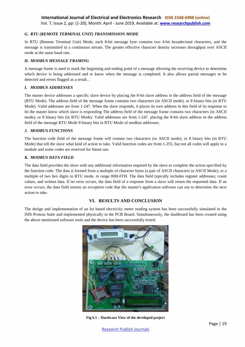
VI. RESULTS AND CONCLUSION
The design and implementation of an Iot based electricity meter reading system has been successfully simulated in the
ISIS Proteus Suite and implemented physically in the PCB Board. Simultaneously, the dashboard has been created using
the above mentioned software tools and the device has been successfully tested.
Fig 6.1 – Hardware View of the developed project
International Journal of Electrical and Electronics Research ISSN 2348-6988 (online) Vol. 7, Issue 2, pp: (1-20), Month: April - June 2019, Available at: www.researchpublish.com
Page | 20 Research Publish Journals
An attempt has been made to make a practical model of „IoT Based Smart Energy Meter.‟ The propagated model is used
to calculate the energy consumption of the household, and even make the energy unit reading to be handy. Hence it
reduces the wastage of energy and bring awareness among all. Even it will deduct the manual intervention.
REFERENCES
[1] Himshekhar Das, L.C.Saikia, “GSM Enabled Smart Energy Meter and Automation of Home Appliances”, PP-978-1-
4678-6503-1, 2015 IEEE.
[2] Ofoegbu Osita Edward, “An Energy Meter Reader with Load Control Capacity and Secure Switching Using a
Password Based Relay Circuit”, PP-978-1-4799-8311-7, „ Annual Global Online Conference on Information and
Computer Technology‟, IEEE 2014.
[3] Yingying Cheng, Huaxiao Yang, Ji Xiao, Xingzhe Hou, “Running State Evaluation Of Electric Energy Meter”,
PP978-1-4799-4565-8, „Workshop on Electronics, Computer and Applications‟, IEEE 2014.
[4] Sahana M N, Anjana S, Ankith S,K Natarajan, K R Shobha, “Home energy management leveraging open IoT
protocol stack “, PP- 978-1-4673-6670-0, „Recent Advances in Intelligent Computational Systems (RAICS)‟, IEEE
2015.
[5] Luigi Martirano,Matteo Manganelli,Danilo Sbordone,„„Design and classification of smart metering systems for the
energy diagnosis of buildings‟‟ IEEE 2015.
[6] J. Widmer, Landis,” Billing metering using sampled values according lEe 61850-9-2 for substations”,IEEE 2014.
[7] Cheng Pang,Valierry Vyatkin,Yinbai Deng, Majidi Sorouri, “Virtual smart metering in automation and simulation of
energy efficient lightning system” IEEE 2013.
[8] Amit Bhimte, Rohit K.Mathew, Kumaravel S, “Development of smart energy meter in labview for power
distribution systems”, “IEEE INDICON 2015 1570186881”, 2015.
[9] H. Arasteh, V. Hosseinnezhad, V.Loia, A.Tommasetti, O.Troisi, M.Shafie Khan, P.Siano, “IoT Based Smart Cities:
A survey”IEEE 978-1-5090-2320-2/1631.00,2016.
[10] Clement N. NYIRENDRE, Irvine NYANDOWE, Linda SHITUMBAPO, “A comparison of the collection tree
protocol (CTP) and AODV routing protocol for a smart water metering.”, PP NO. 1-8,2016.
[11] Nayan Gupta, Deepali Sharma ,“Design of embedded based automatic meter reading system for real time
processing”, 2016 IEEE-SCEEC.
[12] T. Narmada, Dr. M.V. Lakshmaiah, N.N.Nagamma, G. Pakardin, “Raspberry Pi2 based prepaid electricity billing