University of Baghdad
College of Science
Computer Science Department
Design and Implementation of
Pictorial Distributed Database
System A Dissertation
Submitted to the Computer Science Department College of
Science at University of Baghdad in Partial to Fulfillment of the
Requirements for the Degree of Master of Science in Computer
BY
Shalaa Talib Al-Mashhadany
Supervised by
Dr. Rashid A. AL_Zubaidy
(Assist. Prof.)
December 2004 ۱٤۲٥ذو القعدة
بسم الله الرحمن الرحيم
مَا عَلَّمْتـَنَا قاَلُوا سُبْحَانَكَ لا عِلْمَ لنََا إِلاَّ (
) إِنَّكَ أَنْتَ الْعَلِيمُ الْحَكِيمُ
صدق الله العظيم )۳۲(البقرة:
CERTIFICATION
I certify that this dissertation was prepared under my supervision at
the department of Computer Science College of Science at Baghdad
University by Shahlaa Talib Abud alwahab in partial fulfillment of the
requirements for the Degree of Master of Computer Science.
Signature:
Name: Dr. Rashid A. AL_Zubaidy
Date: / / 2004
CERTIFICATION OF THE HEAD OF THE DEPARTMENT
In view of available recommendation I forward this project for the
debate by the examining committee.
Signature:
Name: Mrs. Makia K.Hamad
( Assist. Prof. )
Date: / /2004
Acknowledgements
Thanks are presented to God for giving me the brain,
imagination, and the ability to perform this work.
I would like to give my great thanks to Dr. Rashid for all their supports and valuable advices.
Thanks to every one teach me any letter in all my life and to my
family and friends for all their encouragements.
Shahlaa Talib Al-Mashhadany
2004
i
Abstract
In various fields there is a need to manage geometric, geographic, or
spatial data, which means data related to space. The space of interest can be,
for example, the two-dimensional abstraction of surface of the earth ,
geographic space, the most prominent example –, a man-made space like the
layout of a VLSI design, a volume containing a model of the human brain, or
another 3d-space representing the arrangement of chains of protein
molecules. At least since the advent of relational database systems there have
been attempts to manage such data in database systems.
The thesis presents the design, constructing and implementation of
pictorial distributed databases system and types of image retrieval and how
transfer record contain image field (long raw) in oracle Database between
two servers and benefits in protection images and their information from the
damage and finding same information on more server.
An employment oracle database server for applying pictorial database and
visual basic for pictorial distributed database system and image retrieval.
Different implementations are required for different environments.
Therefore, the thesis invents make Standard alphanumeric database,
Multimedia database and Feature database lay in one database in order that
orphanhood of a facilitation processes which trade with one database for
reducing size, increment speed and facility.
When export and import information from server to another become
necessary an attention to not replication self record in the self-database.
ii
Table of Contents
Chapter One Introduction 1.1 Overview…………………………………………………………...1
Spatial Database Systems…………………………………………..4
1.2 Literature Survey…………………………………………………...6
1.3 Aim of Thesis……………………………………………………....9
1.4 Thesis Outlines
Chapter Two Image Retrieval Systems 2.1 Introduction…………………………………………………………..10
2.2 Evolution of image retrieval systems………………………………...10
2.2.1 Direct Query……………………………………………………..10
2.2.1.1 Descriptions……………………………………………….11
2.2.1.2 Image Features………………………………………........14
2.2.2 Query by Pictorial Example……………………………………..16
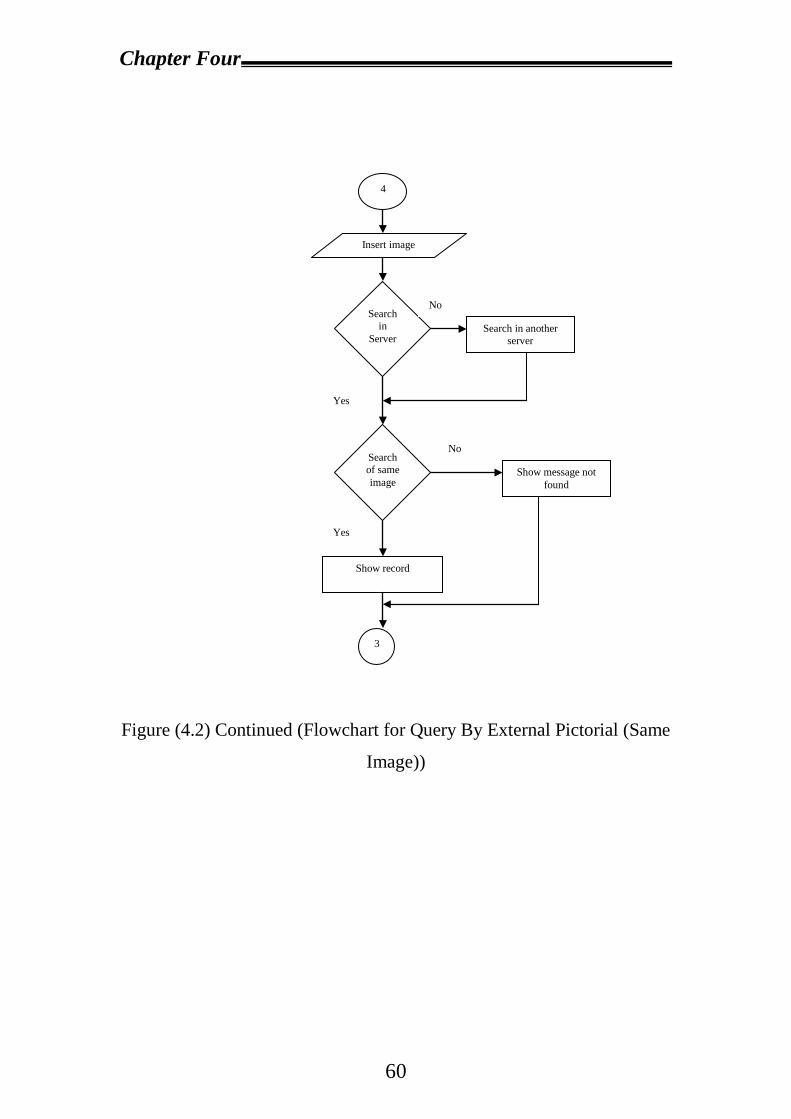
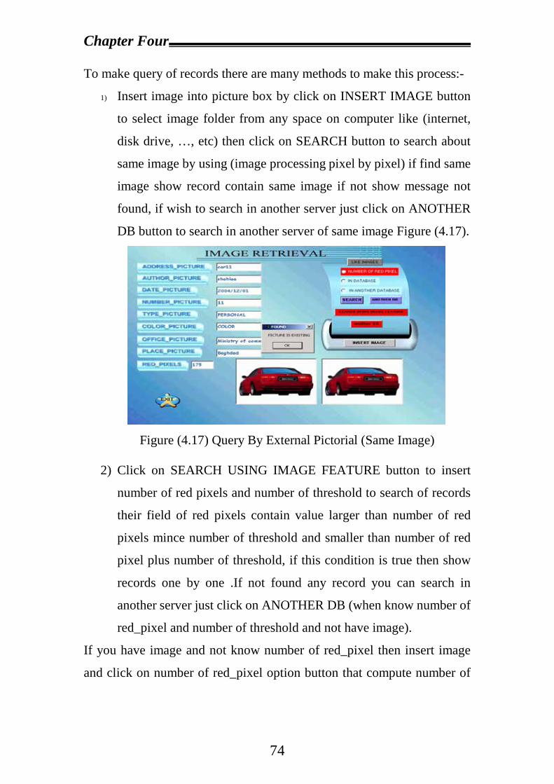
2.2.2.1 Query by external Pictorial Example……………………..19
2.2.2.2 Query by internal Pictorial Example……………………...21
2.2.2.3 Query by Sketch…………………………………………..22
Chapter Three Distributed Databases System 3.1 Introduction…………………………………………………………24
3.2 Network Types……………………………………………………...28
3.2.1 Local-Area networks…………………………………………..29
3.2.2 Wide-area networks…………………………………………...30
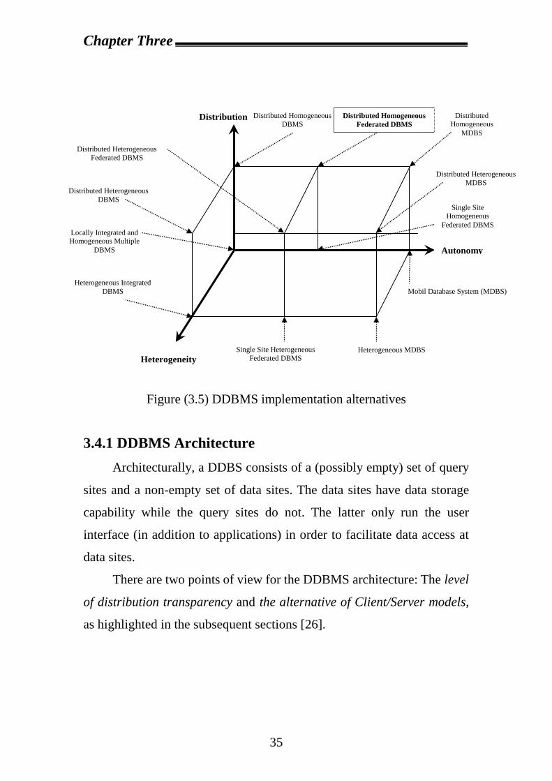
3.3 Homogeneous and Heterogeneous database………………………..33
3.4 Distributed Database Management System………………………...34
iii
3.4.1 DDBMS Architecture…………………………………………35
3.4.1.1 Level of Distribution Transparency……………………36
3.4.1.2 The Alternative of Client/Server Models………………39
3.5 Distributed Database Design………………………………………..45
3.5.1 Alternative Design strategies………………………………….46
3.5.1.1 Top-down design process……………………………...47
3.5.1.2 Bottom-up Design process…………………………….51
3.5.2 Distributed data storage………………………………………52
Chapter Four Proposal System Design and
Implementation 4.1 Introduction…………………………………………………………53
4.2 Proposal System Design……………………………………………53
4.2.1 Design and Create Database in Each Server……………………54
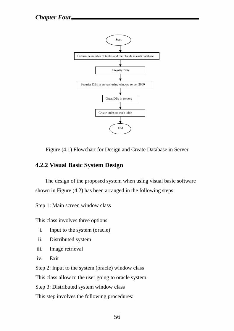
4.2.2 Visual Basic System Design…………………………………….56
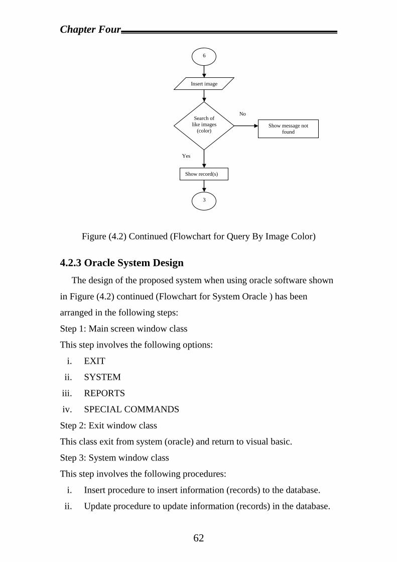
4.2.3 Oracle System Design…………………………………………..62
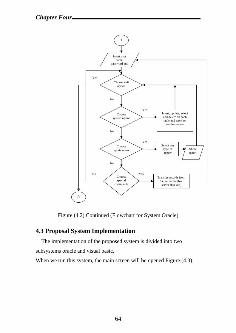
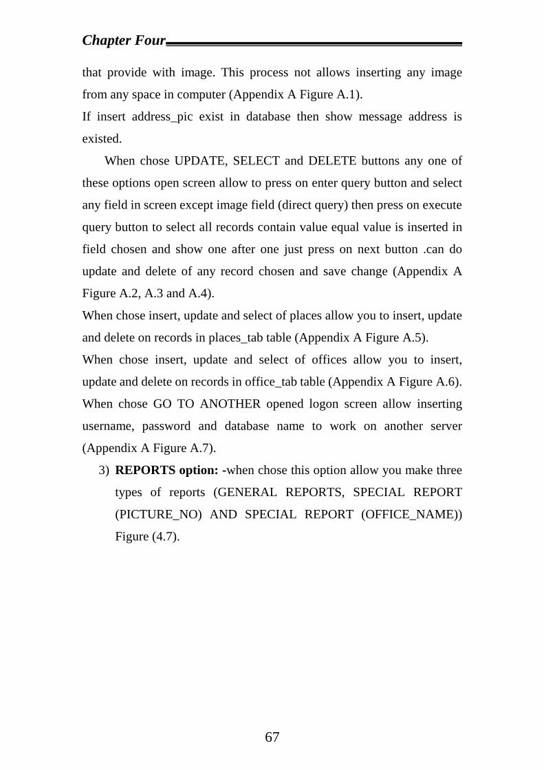
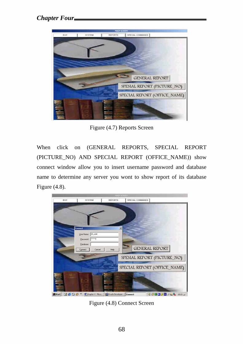
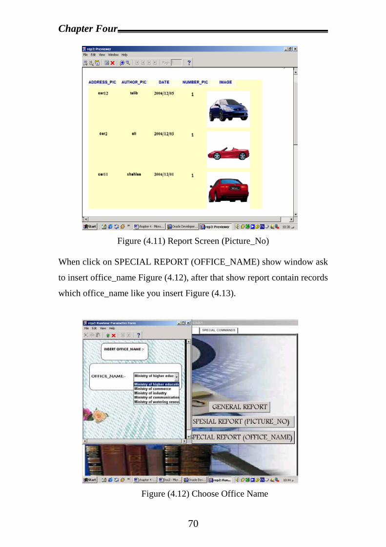
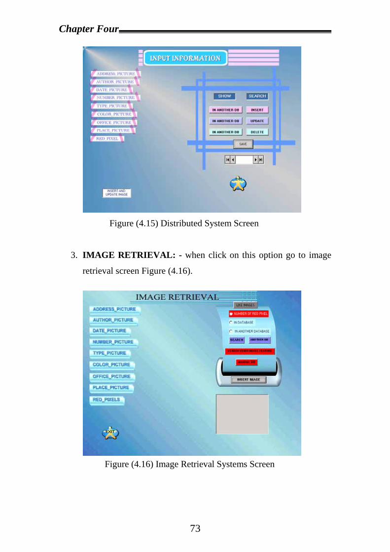
4.3 Proposal System Implementation…………………………………...64
Chapter Five Conclusions and Suggestions
for Future Work
5.1 Conclusions………………………………………………..76
5.2 Suggestions for Future Works……………………………..77
References……………………………………………………..78
Appendix (A)
The List of Abbreviation
ADO Activex Data Object ADODC ADO Data Control BLOBs Binary Large Objects CS Communication System DBMS Database Management System DDB Distributed Database DDBS Distributed Database System DDBMS Distributed Database Management System DSL Digital Subscriber Loop GI Geographic Information GIS Geographic Information System GCS Global Conceptual Schema LANs Local _Area Networks LCS Local Conceptual Schema QBE Query Builder SSD Symposium on large Spatial Database SDTs Spatial Data Types SDI Spatial Database Information SQL Structure Query Language SANs Storage _Area Networks VLSI Very Large Scale Integrated System WANs Wide _Area Networks
Chapter One
1
Chapter One
Introduction
1.1 Overview During the 1970s, database processing typically consisted of
mainframe computers that supported users through terminals connected
directly to the mainframe centralized database system. This centralized
approach to data processing was cost effective. However, the advent of
reasonably priced microcomputers facilitated the placement of
microcomputers at various locations within an organization (i.e., users
could be directly served at various locations). Thus, distributed
processing was born. Rapid advances in both database and networking
technologies address the urgent demand for integration of heterogeneous
and homogeneous collections of data within organizations.
Due to organizational and technological reasons, Distributed
Database (DDB) technology is one of the most important developments
in the past decades and it has become an important area of information
processing. DDBs eliminate many of the shortcomings of centralized
database and fit more naturally in the decentralized structure of many
organizations. A DDB is a collection of data that belong logically to the
same system but are spread over the sites of a computer network. This
defines emphasizes two equally importance aspects of a distributed
database [1]:
a. Distribution: the data are not resident at the same site
(processor), so that DDB can be distinguished from a single,
centralized database.
Chapter One
2
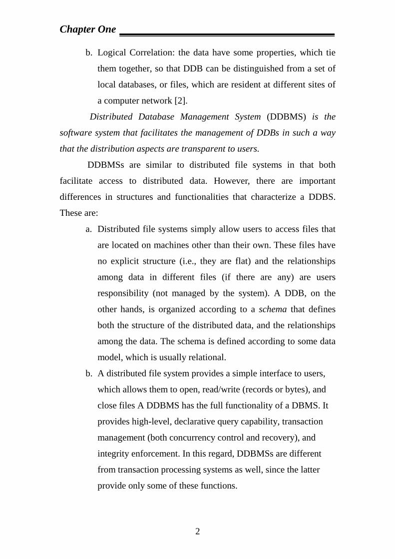
b. Logical Correlation: the data have some properties, which tie
them together, so that DDB can be distinguished from a set of
local databases, or files, which are resident at different sites of
a computer network [2].
Distributed Database Management System (DDBMS) is the
software system that facilitates the management of DDBs in such a way
that the distribution aspects are transparent to users.
DDBMSs are similar to distributed file systems in that both
facilitate access to distributed data. However, there are important
differences in structures and functionalities that characterize a DDBS.
These are:
a. Distributed file systems simply allow users to access files that
are located on machines other than their own. These files have
no explicit structure (i.e., they are flat) and the relationships
among data in different files (if there are any) are users
responsibility (not managed by the system). A DDB, on the
other hands, is organized according to a schema that defines
both the structure of the distributed data, and the relationships
among the data. The schema is defined according to some data
model, which is usually relational.
b. A distributed file system provides a simple interface to users,
which allows them to open, read/write (records or bytes), and
close files A DDBMS has the full functionality of a DBMS. It
provides high-level, declarative query capability, transaction
management (both concurrency control and recovery), and
integrity enforcement. In this regard, DDBMSs are different
from transaction processing systems as well, since the latter
provide only some of these functions.
Chapter One
3
c. In a distributed file system, the user has to know (to some
extent) the location of the data, while a DDBMS provides
transparent access to data.
A DDBMS running on different computer network can handle local
applications autonomously and participates in at least one global
application requiring data from other sites. Communication between
different sites via a communication network is essential for any global
application.
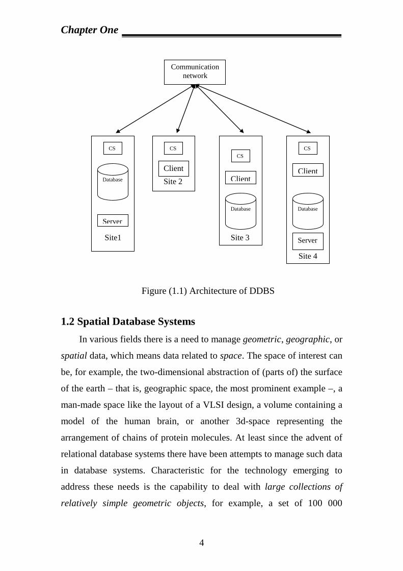
The term Distributed Database System (DDBS) is typically used to
refer to the combination of DDB and the DDBMS. From the architectural
point of view, a DDBS consists of a collection of sites, connected
together via a communication network, as shown in Figure (1.1). The
main parts in this figure are [1]:
a. Client: the front-end of a DDBS where the access requests are
issued.
b. Server: the backend of a DDBS where the database is stored.
c. Communication System (CS): it enables the communication
between client and servers [3].
Chapter One
4
Figure (1.1) Architecture of DDBS 1.2 Spatial Database Systems In various fields there is a need to manage geometric, geographic, or
spatial data, which means data related to space. The space of interest can
be, for example, the two-dimensional abstraction of (parts of) the surface
of the earth – that is, geographic space, the most prominent example –, a
man-made space like the layout of a VLSI design, a volume containing a
model of the human brain, or another 3d-space representing the
arrangement of chains of protein molecules. At least since the advent of
relational database systems there have been attempts to manage such data
in database systems. Characteristic for the technology emerging to
address these needs is the capability to deal with large collections of
relatively simple geometric objects, for example, a set of 100 000
Communication network
Site 4
CS
Client
Database
Server
Site 3
CS
Client
Database
Site 2
CS
Client
Site1
CS
Database
Server
Chapter One
5
polygons. This is somewhat different from areas like CAD databases
(solid modeling etc.) where geometric entities are composed
hierarchically into complex structures, although the issues are certainly
related.
Several terms have been used for database systems offering such support
like pictorial, image, geometric, geographic, or spatial database system.
The terms “pictorial” and “image” database system arise from the fact
that the data to be managed are often initially captured in the form of
digital raster images (e.g. remote sensing by satellites, or computer
tomography in medical applications).
The term “spatial database system” has become popular during the last
few years, to some extent through the series of conferences “Symposium
on Large Spatial Databases (SSD)” held bi-annually since 1989 [8,9, 10],
and is associated with a view of a database as containing sets of objects in
space rather than images or pictures of a space. Indeed, the requirements
and techniques for dealing with objects in space that have identity and
well-defined extents, locations, and relationships are rather different from
those for dealing with raster images. It has therefore been suggested to
clearly distinguish two classes of systems called spatial database systems
and image database systems, respectively [9, 11]. Image database systems
may include analysis techniques to extract objects in space from images,
and offer some spatial database functionality, but are also prepared to
store, manipulate and retrieve raster images as discrete entities. In this
survey we only discuss spatial database systems in the restricted sense.
Several papers in this special issue address image database problems and
so complement the survey.
What is a spatial database system? We are not aware of a generally
accepted definition. The following reflects the author's personal view:
Chapter One
6
(1) A spatial database system is a database system.
(2) It offers spatial data types (SDTs) in its data model and query
language.
(3) It supports spatial data types in its implementation, providing at least
spatial indexing and efficient algorithms for spatial join [4].
1.3 Literature Survey Several models have been used for Spatial Database Systems. In
this section some proposed works of Spatial Database system or other
related works are listed below:
1. Guting Ralf,” An Introduction to Spatial Database Systems”, [4]
Propose a definition of a spatial database system as a database system
that offers spatial data types in its data model and query language and
supports spatial data types in its implementation, providing at least spatial
indexing and spatial join methods. Spatial database systems offer the
underlying database technology for geographic information systems and
other applications. We survey data modeling, querying, data structures
and algorithms, and system architecture for such systems. The emphasis
is on describing known technology in a coherent manner rather than on
listing open problems.
2. Rachev, LLieva and Stoeva,” An Approach for SDI Modeling and Visualization”, [5].
In this paper an approach for SDI modeling and visualization, which is
used in information technology for the GI development process.
In general, one of the interesting fields for spatial data base research is
workflow modeling and visual presentation of results. The proposed
research focuses on the GI manipulating image layers to produce new
Chapter One
7
derived layers. The layers are combined in tree-based manner, starting
with a large number of source layers and producing new layers until a
final result layer is produced. Information about dependence among
layers is useful for change of propagation if the source layers are
modified.
Also, we propose a proper visualization process for the resulting SDI
layer by specifically chosen and combined new generated textures in
order to get a higher visualization quality, and in the same time – to
improve their accurate, rapid and easy visual investigation. Users must
determine tasks like: searching for data elements with unique visual
properties, defining the boundaries between groups with similar features,
evaluating the number of data with a specific feature only with a glance at
the image.
3. Park Jinsoo,” Spatial Data Modeling: Issues and Implications on Geographic Information Systems”, [6].
Even though the potential ability of Geographic Information System
(GIS) as decision support for business activities has been widely
recognized, the topic of Geographic Information Systems (GIS) has
received little attention in the business literature. Spatial database systems
provide the underlying database technology for Geographic Information
Systems and other applications. Modeling spatial objects and their
operations in spatial databases is a relatively new research area. Spatial
data models should include constructs of high-level abstractions, spatial
entities, relationships, operators and a query language, which provides
rich concepts to efficiently and effectively handle spatial data. We present
a comprehensive survey of the current state-of-the-art in spatial
databases.
Chapter One
8
4. Ning and Sun Jing,” Spatial Database Techniques Oriented to Visualization in 3D GIS”, [7].
Spatial database is the heart of GIS. Now most researches on 3D GIS
focus on visualization and virtual reality techniques, and neglect 3D
spatial database. Few traditional spatial databases are used in 3D
applications; thereafter many 3D visualization techniques can't be
integrated with spatial database in 3D GIS. Since there exist few
interconnections between spatial database and visualization, many GIS
functions and visualization techniques can't be implemented at the same
time. This paper discusses implementation of some basic spatial database
techniques in 3D GIS on object-oriented database. In order to implement
generalization at multi-scale, we try to extend, improve and optimize
some index techniques and proposes V-Reactive tree, by which some 3D
visualization techniques (e.g. level of detail) at multi-scale can come true.
On the multi-scale spatial index, perspective query can utilize idea of
level of detail for reducing time complexity of spatial query greatly. This
paper also describes architecture of 3D GIS built on object-oriented
database. Based on spatial query and buffer management, our 3D GIS
system makes some progresses on 3D visualization, interactive interface,
and etc., which are also the foundation of some virtual reality functions.
Finally, we give some initial experimental results and analyze the
proposed spatial database techniques, as well as discus their
characteristics and limitations.
Chapter One
9
1.4 Aim of Proposed System Design, Constructing and implementation of pictorial distributed
database system using oracle and visual basic for purpose saving and
retrieving information in database.
1.5 Thesis Outlines This is the summary of the contents of the subsequent chapters of this project:
· Chapter two: This chapter describes the evolution from image retrieval based on the data retrieval methods in conventional databases to methods specifically designed for images.
· Chapter Three: this chapter presents the theoretical concepts
needed in this project at which introduction to DDBs, a description of Database systems, computer networks, and Distributed DBMSs are presented.
· Chapter Four: this chapter discusses the design and implementation
of pictorial distributed database system.
· Chapter Five: this chapter focuses on the discussion and conclusions, and presents the recommendation for the future developments to the proposed system.
Chapter Two
10
Chapter Two
Image Retrieval Systems
2.1 Introduction
There are many ways in which images can be retrieved. This
chapter describes the evolution from image retrieval based on the data
retrieval methods in conventional databases to methods specifically
designed for images. In section 2.2, seven image retrieval methods are
introduced, which are grouped into three main types.
2.2 Evolution of image retrieval systems
Image retrieval systems have evolved from approaches based on data
about the images (section 2.2.1.) to retrieval forms based on the image
data (section 2.2.2.).
2.2.1 Direct Query
Conventional database systems offer an image retrieval method called
Direct Query. Direct Query is the retrieval method in which a query for
images consists of formatted facts only.
The Direct Query method requires that formatted facts about the
image are available, because pictorial data can't be processed by
conventional database systems for two reasons:
· Data structure. The database fields used in the query have to be of
the same data types as the data queried. Consequently, when a user
queries the raw image data in the database, the query has to contain
Chapter Two
11
raw image data too. However, it is not likely that the user can
provide the image in the query, because that is his information
need.
· Exact matches. A direct query divides a collection of data items
into two groups. One group contains the data that comply with the
search conditions; the other group consists of the data that do not
comply with the conditions. However, there is no definition for a
range of images, such as 1 to 5 for numbers or x to z for
alphanumeric strings. Therefore, a traditional database system can
query the database only for the presence of an image.
Formatted facts are abstractions from the real world. When for
example the name and age of a person are stored in the database, the
system contains data about an entity in the real world. This means a
traditional database can handle images, just as long as the images are
abstracted to facts in a format the system provides formalizations for.
It should be noted that images too are abstractions from the real world,
but this is a low level conversion from real world objects to raw digital
image data in which no semantics are introduced.
Next, two forms of Direct Query are discussed. The first form uses
descriptions of the images to find images (section 2.2.1.1). The second
form retrieves images by deriving features from the raw image data
through image analysis techniques (section 2.2.1.2).
2.2.1.1 Descriptions
The most obvious way to abstract images is to describe them with
words. These abstractions are called descriptions or annotations. Direct
Query on Descriptions is the retrieval method in which a query for
Chapter Two
12
images consists of values of user-specified features only. Values for
user-specified features [15] are associated with images by their context,
e.g. the knowledge of a human or the caption of the image, at insertion
time.
For example, pictures of cars can be indexed by descriptions of the
color and of the brand of the car. To retrieve images a user can express
his information need in a database query language, such as SQL [13]:
The conditions in the query refer to the descriptions only, but the query
result consists of the raw image data: the pictures of all red Porsches in
the database.
Other than facilities for the storage and presentation of images, the
database system does not need any new functionality for this type of
Direct Query. With this approach the user can retrieve images even in
basic, commercial database systems such as Microsoft Access and
Borland Paradox. Such systems store the images as BLOBs (Binary
Large Objects).
Direct Query on Descriptions requires a great deal of indexing
efforts. For large image collections manual indexing is not feasible in
practice, unless descriptions are already available for other purposes. E.g.,
in mail order catalogues products are described and accompanied by a
picture. Since both the description and the picture are an abstraction of
the same object, the descriptions can be used to retrieve the images.
Advanced techniques to generate descriptions from the context of
an image are available. [19] Describes the Piction system which identifies
human faces in newspaper photographs with the help of visual semantics
and natural language processing. Piction uses the caption of an image to
Chapter Two
13
associate a term with a photograph, or even a part of the photograph. The
indexing is performed fully automatically by a computer system. The
retrieval of the images is based purely on the descriptions; the images are
not compared to one another.
The efforts for assigning keywords to images may be
surmountable; the ambiguity of the descriptions remains to be a problem.
Techniques from natural language processing, e.g. dictionaries, can be of
assistance to reduce ambiguity problems. Still, if an image is assigned a
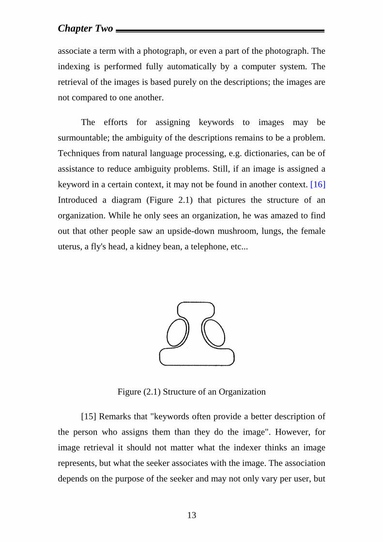
keyword in a certain context, it may not be found in another context. [16]
Introduced a diagram (Figure 2.1) that pictures the structure of an
organization. While he only sees an organization, he was amazed to find
out that other people saw an upside-down mushroom, lungs, the female
uterus, a fly's head, a kidney bean, a telephone, etc...
Figure (2.1) Structure of an Organization
[15] Remarks that "keywords often provide a better description of
the person who assigns them than they do the image". However, for
image retrieval it should not matter what the indexer thinks an image
represents, but what the seeker associates with the image. The association
depends on the purpose of the seeker and may not only vary per user, but
Chapter Two
14
also per image retrieval session as the purpose of one particular seeker
can change. In conclusion, the two major disadvantages of Direct Query
on Descriptions are the indexing efforts it requires and the ambiguity of
the descriptions. The advantage of the method is that it the retrieval is
based on the semantics of the images. In domains where each object has
one unique description, Direct Query on Descriptions will be very
powerful.
2.2.1.2. Image Features
The second form of Direct Query is based on the use of image
features, which are visual characteristics of an image. Direct Query on
Image Features is the retrieval method in which a query for images
consists of values directly derived from raw image data only. An
image feature is an abstraction of an image to numeric values that a
computer can process. It is a non-information-bearing attribute of the
image.
Features can vary from simple measures, such as the number of red
pixels in an image, to properties of objects in an image, e.g. the shape of
an object. An implementation of the former case is very well feasible in a
conventional database without any extensions, because databases are well
equipped to handle numbers. The latter case is more complex and
requires specific data types to store geometrical data in the database. For
example, geographical databases (closely related to image databases) are
equipped with datatypes and operators that allow queries on the geometry
and topology of objects. Such databases handle objects with known and
consistent formats.
Chapter Two
15
To find the pictures of a red car in a database of cars, again a query
in SQL can be formulated. Suppose the field "red pixels" in the database
contains a value for the percentage of pixels in an image which are red.
Again, a query can be composed in SQL:
The query is not complex at all, but it will only be successful when
the user chooses good parameters. The query is based on a threshold. If
the condition in the query only constrains the result to images containing
red pixels, even pictures of cars with a small red sticker on the window
would be retrieved. The user is challenged to set a good threshold: high
enough to discard pictures with small red areas, but low enough to allow
the retrieval of small red cars.
A good threshold is no guarantee for the retrieval of red cars only.
The color of the cars has to dominate the pictures. I.e. when the cars were
photographed in front of a red wall, the wall should not cover a large part
of the image. Otherwise a small blue car in front of a large red wall will
be part of the query result. Such problems are bound to arise when the
database consists of not only car images, but pictures from other domains
as well.
The main advantage of Direct Query on Image Features is the
possibility for automatic feature extraction from the images. Once an
extraction procedure is set up, it requires no human efforts to encode the
images. Compared to human processing costs, computer processing time
is relatively cheap.
Further, the use of a predefined model guarantees an objective
abstraction of an image. As stated before, for indexing by annotations
usually a team of humans is employed. Each team member may have his
Chapter Two
16
own subjective interpretation of the image. In a 'team' of automatic
feature extractors all members are clones of one model. Each team
member thinks and acts alike. On the other hand, humans are far more
flexible than their digital colleagues. The designer of the feature
extraction model has to anticipate on all possible contents of the images,
while human indexers can use the complex models given to them at birth
in combination with their lifelong visual experience.
In conclusion, the advantage of the Direct Query on Image
Features method is that the abstractions can be derived from images
automatically and objectively. The disadvantage is that the formulation of
queries is difficult for general users because the conditions have to
contain image feature values. Applications of retrieval systems using
image features are usually restricted to specific domains to reduce the
complexity of the feature extraction model needed.
2.2.2 Query by Pictorial Example
The use of image features does not seem very fruitful in the case of
Direct Query, but this does not at all mean that the use of image features
is wrong. In fact, most image retrieval techniques nowadays use image
features. In 1980 Change [12] introduced the concept of Query by
Pictorial Example, which was based on the Query By Example concept
for alphanumeric data. Query by Pictorial Example is the retrieval
method in which a query for images consists of one or more images.
In Query By Example a user formulates a query by filling in fields
in a skeleton table. Fields can be filled with a condition or they can be left
empty. Compared to query languages as SQL, QBE is more transparent to
Chapter Two
17
the user who has to compose a query. QBE is not suitable for complex
(nested) queries.
As part of the Query by Pictorial Example approach [12] talked
about similarity operators. Besides an abstraction of the raw image data a
method for matching the abstracted data is needed. The introduction of
the similarity match instead of the exact match causes a shift from a
database division operation to a look-alike contest.
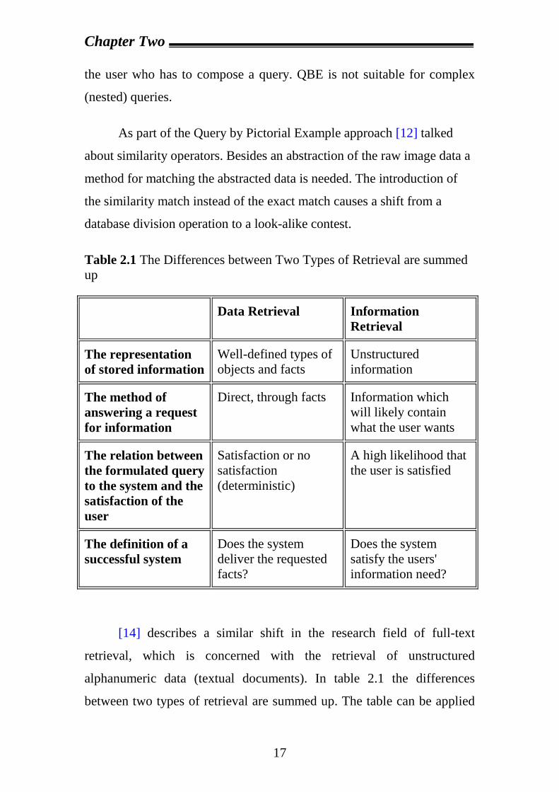
Table 2.1 The Differences between Two Types of Retrieval are summed up
[14] describes a similar shift in the research field of full-text
retrieval, which is concerned with the retrieval of unstructured
alphanumeric data (textual documents). In table 2.1 the differences
between two types of retrieval are summed up. The table can be applied
Data Retrieval Information Retrieval
The representation of stored information
Well-defined types of objects and facts
Unstructured information
The method of answering a request for information
Direct, through facts Information which will likely contain what the user wants
The relation between the formulated query to the system and the satisfaction of the user
Satisfaction or no satisfaction (deterministic)
A high likelihood that the user is satisfied
The definition of a successful system
Does the system deliver the requested facts?
Does the system satisfy the users' information need?
Chapter Two
18
to the field of image retrieval without a change. Data retrieval is the
equivalent of Direct Query, while information retrieval can be compared
to the Query by Pictorial Example concept and its similarity match.
As can be seen in table 2.1, information retrieval is based on
likelihoods. When a user queries a collection of documents, the
information retrieval system returns a number (the so-called relevance)
for each document in the collection. The relevance number is the extent to
which a document matches the query. If for example the query is a
request for documents containing the word 'Porsche', a document that
contains the word ten times will have a higher number than a text that
mentions the word only twice. Using relevance ranking, the system
presents a list of all documents in the database ordered according to the
computed relevance number. The user can start at the top of the list to
evaluate the documents that are most likely to comply with his query.
Although the features for computing the relevance number differ a
lot, Query by Pictorial Example uses the same principle as full-text
information retrieval to satisfy a user's information need. A user can for
example provide the image retrieval system with a picture of a red car,
asking for all pictures that look alike. The system computes the values for
the features of the example image and compares them to the values of the
images in the database. Using the 'red pixels' feature again, a blue car
with a red sticker now would get a higher ranking than a picture of a blue
car containing no red pixels at all. However, the blue car will not turn up
in the top of the relevance ranking list, which is dominated by red cars
and perhaps cars before big red walls. In Query by Pictorial Example, the
system's purpose has changed from giving deterministic answers to
minimizing the user's search and evaluation efforts.
Chapter Two
19
Query by Pictorial Example systems introduce a new challenge for
researchers. Besides the choice for features, methods for similarity
matching have to be defined. Unlike the exact match operator, a similarity
match operator for a feature can be defined in many ways.
In addition to the image features and similarity methods, the
example image used to query the database is of butter importance. We
have classified three subtypes of Query by Pictorial Example based on the
way the example image is acquired:
· the example images are fed to the system from the outside (section
2.2.2.1.);
· the example images are chosen from the existing database (section
2.2.2.2.);
· the user constructs a whole new image as an example image
(section 2.2.2.3.).
2.2.2.1 Query by external Pictorial Example
Query by external Pictorial Example is the form of Query by
Pictorial Example in which example images are provided to the
retrieval system by an external source. This means that the image is not
stored in the database. A user can for example digitize a photograph or
find a nice image on Internet or elsewhere. The user can then ask the
system for similar images in the database.
For example, an organization that registers trademarks can look in
its archives if a new trademark does not look too much like trademarks
already registered [20]. Law enforcement agencies can use Query by
external Pictorial Example to compare tracks to information in criminal
records.
Chapter Two
20
[18] describe a system to find fingerprints similar to a forensic
sample fingerprint to link the sample to a person. Such databases can
grow very large: in 1994 the United States FBI had archived 114 million
fingerprint cards, each containing ten fingerprints.
One can also imagine other law enforcement applications of Query
by external Pictorial Example. E.g., police can provide the retrieval
system with a photograph of a robber taken by a security camera. The
system then returns a list of mug shots similar to the photo provided.
The advantage of Query by external Pictorial Example is the ease
of expressing the information need for the user. The user just has to
provide one or more images and may be he adjusts some parameters
(weigh factors for the features used). Knowledge of a specific query
language is not required.
It should be noted that although the user provides images to the
system, the system does not exactly look for similar images. The system
looks for images with similar feature values, which may be confusing to a
novice user of Query by external Pictorial Example.
If it is hard for the user to come up with an example image, the
power of Query by external Pictorial Example decreases. The effort for
finding an example image should not extend the effort to find an image in
the database.
In conclusion, the advantage of the Query by external Pictorial
Example method is its ease of use. The disadvantage of the method is the
effort needed for the acquirement of an image.
Chapter Two
21
2.2.2.2 Query by internal Pictorial Example
Query by external Pictorial Example is the form of Query by
Pictorial Example in which example images are chosen from the
retrieval system's database. When an external image example is not
available, the user can select a query image from the available image
collection. Further, the system has the same functionality as Query by
external Pictorial Example.
A comparison to the example in the previous section about the
retrieval of mug shots on the basis of a photograph from a security
camera will show the difference between an internal and an external
example. When there is no security camera to tape the robbery, the police
has to rely on witnesses. A witness does not have to search for the suspect
by looking at all mug shots available. Using Query by Pictorial Example,
he can select an image of someone who looks like the suspect (e.g.
because they have the same hair color) and then use the result to quickly
find the suspect from the look-alikes.
The advantage of Query by internal Pictorial Example is that there
is no need for the capture or construction of an image in order to use
Query by Pictorial Example.
However, the user first has to find an example image in the
database, which can be time consuming as well. Query by internal
Pictorial Example is always used in combination with other retrieval
methods to overcome this problem. Photobook [17] uses Query by
internal Pictorial Example after a reduction of the image set by a Direct
Query.
Chapter Two
22
In conclusion, the advantage of the Query by internal Pictorial
Example method is that the user is not bothered with acquiring an
example image. The disadvantage of the method is the effort that has to
be made for selection of an appropriate example image.
2.2.2.3 Query by Sketch
Query by external Pictorial Example is the form of Query by
Pictorial Example in which example images are constructed by the
user. The user draws a sketch of the image he's looking for. [15]
Mentions a variant on this approach called Query Canvas. In Query
Canvas, the user combines and edits existing pictures in order to compose
an example image. The retrieval system may provide the user with parts
of an image (such as textures) and tools for drawing.
Again using the example of the search for a suspect of a robbery,
the mug shot can now be found by feeding the system with a composed
sketch of the suspect. A police artist can draw a picture based on the
statements of witnesses. Sometimes witnesses compose a face by
combining photographs of body parts, such as hair, noses and eyes.
In contrast to images of real world scenes, sketches have a high
form of abstraction. The user does draw only the important parts of the
image he's looking for. Query by Sketch thus has an advantage over
Query by Example using existing pictures.
The disadvantage of Query by Sketch is that it requires a user with
some artistic capabilities. Since many users do not have such capabilities,
Query by Sketch is mostly used to specify the positions of objects in an
image and some global characteristics of the objects. Further the
Chapter Two
23
difference in syntax between the query image and the collection of
images queried makes the measure for similarity non trivial.
In conclusion, the advantage of the Query by Sketch method is that
the user can specify his information need by indicating only the most
important details of an image. The disadvantage is the difficulty of the
creation of a sketch and its mapping to images in the database.
Chapter Three
24
Chapter Three
Distributed Databases System
3.1 Introduction
So far have been discussing centralized database system, with the
database located at a central computing facility. In this kind of system,
users and application programs access a single database from local sites
as from remote locations.
A distributed database system, the database is stored on several
computers. The computers in distributed system communicate with one
another through various communication media, such as high-speed
networks or telephone lines. They do not share main memory or disk. The
computers in a distributed system may vary in size and function, ranging
from workstations up to mainframe systems.
The computers in a distributed system are referred to by a number
of different names, such as sites or nodes, depending on the context in
which they are mentioned.
Mainly use the term site, to emphasize the physical distribution of
these systems. The general structure of a distributed system appears in
Figure (3.1).
Chapter Three
25
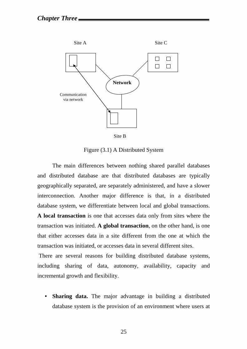
Figure (3.1) A Distributed System
The main differences between nothing shared parallel databases
and distributed database are that distributed databases are typically
geographically separated, are separately administered, and have a slower
interconnection. Another major difference is that, in a distributed
database system, we differentiate between local and global transactions.
A local transaction is one that accesses data only from sites where the
transaction was initiated. A global transaction, on the other hand, is one
that either accesses data in a site different from the one at which the
transaction was initiated, or accesses data in several different sites.
There are several reasons for building distributed database systems,
including sharing of data, autonomy, availability, capacity and
incremental growth and flexibility.
· Sharing data. The major advantage in building a distributed
database system is the provision of an environment where users at
Network
Communication via network
Site A
Site C
Site B
Chapter Three
26
one site may be able to access the data residing at other sites. For
instance, in a distributed banking system, where each branch stores
data related to that branch, it is possible for a user in one branch to
access data in another branch. Without this capability, a user
wishing to transfer funds from one branch to another would have to
resort to some external mechanism that would couple existing
systems.
· Autonomy. The primary advantage of sharing data by means of
data distribution is that each site is able to retain a degree of control
over data that are stored locally. In a centralized system, the
database administrator of the central site controls the database. In a
distributed system, there is a global database administrator
responsible for the entire system. A part of these responsibilities is
delegated to the local database administrator for each site.
Depending on the design of the distributed database system, each
administrator may have a different degree of local autonomy. The
possibility of local autonomy is often a major advantage of
distributed databases.
· Availability. If one site fails in a distributed system, the remaining
sites may be able to continue operating .In particular, if data items
are replicated in several sites, a transaction needing a particular
data item may find that item in any of several sites. Thus, the
failure of a site does not necessarily imply the shutdown of the
system.
The failure of one site must be detected by the system, and
appropriate action may be needed to recover from the failure .The
system must no longer use the services of the failed site. Finally, when
the failed site recovers or is repaired, mechanisms must be available to
integrate it smoothly back into the system.
Chapter Three
27
Although recovery from failure is more complex in distributed
systems than in centralized systems, the ability of most of the system
to continue to operate despite the failure of one site results in
increased availability [21].
· Capacity and incremental growth. When adding a new node or
new data location (e.g. new table), there's' no need to re _configure
the whole database the new node almost automatically becomes a
part of the global database.
· Flexibility. Moving data from one place to another (due to
management decision) or changing physical location of certain
nodes requires no change in the database or its architecture [22].
The primary disadvantage of distributed database systems is the add
complexity required to ensure proper coordination among the sites. This
increased complexity takes various forms:
· Software _development cost. It is more difficult to implement a
distributed database system; it is more costly.
· Greater potential for bugs. Since the sites that constitute the
distributed system operate in parallel, it is harder to ensure the
correctness of algorithm, especially operation during failures of
part of the system, and recovery from failures. The potential exists
for extremely subtle bugs.
· Increased processing overhead. The exchange of messages and
the additional computation required to achieve intersite
coordination are a form of overhead that does not arise in
centralized systems [21].
Chapter Three
28
There are additional disadvantages of distributed database systems: -
· Reliability/Efficiency. The parallel nature of the system means
that errors are harder to avoid and those in the applications are
difficult to pinpoint. By trying
To make the distributed database more reliable we pay (greatly)
by reducing efficiency communication overhead In addition, the
distributed system, by its very nature, entails a large communication
overhead in coordinating messages and transactions between the
different sites.
· Integrity. Due to the fact that not all data is located in one
centralized place-a station (node) failure might cause aloes of data
for other nodes. In the next chapter we shell discuss methods,
which minimize thus effect.
· Cost. Increased complexity means that the acquisition and
maintenance costs of the system are much higher than those of
centralized DBMS [22].
3.2 Network Types [21] Distributed databases and client –server systems are built around
communication networks. There are basically two types of networks:
local-area networks and wide area networks. The main difference
between the two is the way in which they are distributed geographically
.In local–area networks, processors are distributed over small
geographical areas, such as a single building or a number of adjacent
buildings In wide –area networks, on the other hand, number of
autonomous processors are distributed over a large geographical area
(such as the united states or the entire world). These differences imply
Chapter Three
29
major variations in the speed and reliability of the communication
network, and are reflected in the distributed operating –system design.
3.2.1 Local-Area networks Local-area networks (LANs) (Figure 3.2) emerged in the early
1970s as away for computers to communicate and to share data with one
another. People recognized that, for many enterprises, numerous small
computers, each with its own self-contained applications, are more
economical than a single large system. Because each small computer is
likely to need access to a full complement of peripheral devices (such as
disks and printers), and because some form of data sharing is likely to
occur in a single enterprise, it was a natural step to connect these small
systems into a network.
LANs are generally used in an office environment. All the sites in
such systems are close to one another, so the communication links tend to
have a higher speed and lower error rate than do their counterparts in
wide-area networks. The most common links in alocal-areanetwork are
twisted pair, coaxial cable, fiber optics, and, increasingly, wireless
connections. Communication speeds range from a few megabits per
second (for wireless local-area networks), to 1 gigabit per second for
Gigabit Ethernet. Standard Ethernet runs at 10 megabits per second, while
fast Ethernet run at 100 megabits per second.
A storage-area network (SAN) is a special type of high-speed
local-area network designed to connect large banks of storage devices
(disks) to computers that use the data. Thus storage-area networks help
builds large-scale shared_disk systems. The motivation for using
storage_area networks to connect multiple computers to large banks of
storage devices is essentially the same as that for shared_disk databases,
namely
Chapter Three
30
· Scalability by adding more computers
· High availability, since data is still accessible even if a computer
fails.
Figure (3.2) Local-Area Network
3.2.2 Wide-area networks
Wide-area networks (WANs) emerged in the late 1960s, mainly as
an academic research project to provide efficient communication among
sites, allowing hardware and software to be shared conveniently and
economically by a wide community of users. System that allowed remote
terminals to be connected to a central computer via telephone lines were
developed in the early 1960s, but they were not true WANs.The first
gateway
Processors
File server workstation PC
Processors
workstation printer CPU server
Chapter Three
31
WAN to be designed and developed was the Arpanet.Work on the
Arpanet began in 1968.the Arpanet has grown from a four-site
experimental network to a worldwide network of networks, the internet,
comprising hundreds of millions of computer systems. Typical links on
the Internet are fiber_optic lines and, sometimes, satellite channels. Data
rates for wide_area links typically range from a few megabits per second
to hundreds of gigabits per second. The last link, to end user sites, is often
based on digital subscriber loop (DSL) technology supporting a few
megabits per second, or cable modem (supporting 10 megabits per
second), or dial_up modem connections over phone lines (supporting up
to 56 kilobits per second).
· In discontinuous WANs, such as those based on wireless
connections, hosts are connected to the network only part of the
time.
· In continuous connection WANs, such as the wired Internet, hosts
are connected to the network at all times [21].
Figures (3.3) and (3.4) given possible network configurations. Two
configurations for WANs are illustrated in Figure (3.3). LAN design
usually follows the architectures shown in Figure (3.4).
The fully connected configuration of Figure (3.3-A) requires [n (n_1)]/2
links, where n is the number of sites .As this term is of order n^2, the
number of links grows very rapidly with the number of sites, as does the
expense of installation and maintenance. Even though the fully connected
configuration provides the greatest flexibility and reliability, most
installations use partially connected network architecture as the most cost
effective implementation design.
Chapter Three
32
Each site in a distributed database system should be able to process
transactions that access data only at that site, as well as transactions that
require data from other sites. The choice of one configuration over an
other is usually a function of
1. The cost of sending a message from station A to station B
2. The frequency with which a link or station fails (reliability)
3. The degree to which data can be accessed despite the failure of
some links or stations (availability)
4. The frequency and volume of data that must be accessed
5. The cost of physically linking the stations in the system.
The complexity of optimal network design is that it is impossible to
state generally what configurations these factors favor. It depends on such
things as communications volume, communications timing, network
transmission media, and other similar factors. Analytical models are
beginning developed to assist in choosing the best configuration in
specific situations [24].
Figure (3.3) Fully Connected and Partially Connected Network
1
3 4
2
3 4
1 2
(A) Fully Connected
(B)
Partially Connected
Chapter Three
33
Figure (3.4) Network Configurations
3.3 Homogeneous and Heterogeneous database [21] In a homogeneous distributed database, all sites have identical
database management system software, are aware of one another, and
agree to cooperate in processing users requests. In such asystem, local
sites surrender a portion of their autonomy in terms of their right to
change schemas or database management system software. That software
must also cooperate with other sites in exchanging information about
transactions, to make transaction processing possible across multiple
sites.
In contrast, in a heterogeneous distributed database, different sites
may use different schemas, and different database management system
software. The sites may not be aware of one another, and they may
provide only limited facilities for cooperation in transaction processing
the differences in schemas are often a major problem for query
2
3 4
2 1
4 1
2 3
4
1
3
(a) Bus
(b) Ring
(c) Star
Chapter Three
34
processing, while the divergence in software becomes a hindrance for
processing transactions that access multiple sites.
3.4 Distributed Database Management System Basically, there are three dimensions for database, DDBMSs, and
application. Figure (3.5) shows the alternatives in implementing
DDBMSs:
a. Distribution: means that database, DDBMSs, and applications can
be located centrally
or distributed in a network.
b. Autonomy: means that the control of database, DDBMSs, and
applications can be done centrally, autonomous, or in between.
c. Heterogeneity: means that database, DDBMSs, and application
can be of the same type or of different types [25].
In general, within a homogeneous distributed system each site
runs its own copy of the same DBMS. More precisely, the DBMS at
different site all support the same data model and the same database
operations. Within a heterogeneous distributed system different DBMSs
at different sites support different data models and/or different database
operations. There is no point in building a heterogeneous system from
scratch. But there might be advantages in connecting together a set of
pre_existing centralized DBMSs to form a distributed system.
Chapter Three
35
Figure (3.5) DDBMS implementation alternatives
3.4.1 DDBMS Architecture Architecturally, a DDBS consists of a (possibly empty) set of query
sites and a non-empty set of data sites. The data sites have data storage
capability while the query sites do not. The latter only run the user
interface (in addition to applications) in order to facilitate data access at
data sites.
There are two points of view for the DDBMS architecture: The level
of distribution transparency and the alternative of Client/Server models,
as highlighted in the subsequent sections [26].
Autonomy
Mobil Database System (MDBS)
Heterogeneous MDBS Single Site Heterogeneous Federated DBMS Heterogeneity
Heterogeneous Integrated DBMS
Locally Integrated and Homogeneous Multiple
DBMS
Distributed Heterogeneous DBMS
Distributed Heterogeneous Federated DBMS
Distribution Distributed Homogeneous DBMS
Distributed Homogeneous Federated DBMS
Distributed Homogeneous
MDBS
Distributed Heterogeneous MDBS
Single Site Homogeneous
Federated DBMS
Chapter Three
36
3.4.1.1 Level of Distribution Transparency The reference architecture for a DDB is defined to represent
different level of distributed transparency. Figure (3.6) shows the
reference architecture for a DDB.
Figure (3.6) Reference architecture for distributed databases. At the top level of this architecture is the global schema. The global
schema defines all the data that are contained in the DDB as if the
database were not distributed at all; i.e., the global schema consists of the
definition of a set of global relations.
Global Schema
Fragmentation Schema
Allocation Schema
Local Mapping Schema 2
Local Mapping Schema 1
DBMS of
site 1
DBMS of
site 2
Local Database at site 1
Local Database at site 2
Site Independent Schemas
(Other sites)
Chapter Three
37
Each global relation may be split into several non-overlapping
portions that are called fragments. Fragments are Logical portions of
global relations that are physically located at one or several sites of the
network. The mapping between global relations and fragments is defined
in the fragmentation schema. This mapping is one to many; i.e., several
fragments correspond to one global relation, but only one global relation
corresponds to one fragment.
The allocation schema defines at which site(s) a fragment is
located. The type of mapping defined in the allocation schema determines
whether the DDB is redundant or non-redundant; the mapping is one to
one. All the fragments that are correspond to the same global relation R
and are located at the same sit j constitute the physical image of global
relation R at site j. There is, therefore, a one to one mapping between a
physical image and a pair (global relation, site).
These three levels are site independent: therefore, they do not
depend on the data model of the local DBMSs. At a lower level, it is
necessary to map the physical images to the objects that are manipulated
by local DBMSs. This mapping is called a local mapping schema and
depends on the type of the type of local DBMS. In a homogeneous
system, there is no need for the local mapping schema. While in a
heterogeneous system, there are different types of local mapping at
different sites. This architecture provides a very general conceptual
framework for understanding DDBs. The three most important objectives
that motivate the features of this architecture are:
a. Separating of concept of data fragmentation from the concept
of data allocation.
This separation distinguishes two different levels of distribution
transparency, namely fragmentation transparency and location
transparency. Fragmentation transparency is the highest degree
Chapter Three
38
of transparency and consists of the fact that the user or
application programmer works on global relations. Location
transparency is a lower degree of transparency and requires the
user or application programmer to work on fragments instead
of global relation, without knowing where the fragments are
located. The separation between the concept of fragmentation
and allocation is very convenient in DDB design, because the
determination of relevant portions of the data is thus
distinguished from the problem of optimal allocation.
b. Explicit control of redundancy. The reference architecture
provides explicit of redundancy at the allocation level. For
example, two physical images R¹ and R² of a relation R can be
overlapping; i.e., they contain common data. The definition of
disjoint fragments as building blocks of physical images allows
the explicit referencing to these overlapping parts; the
replicated fragment R2, as shown in figure (3.7). Generally, Ri
indicates the ith fragment of global relation R and Rj indicates
the physical image of the global relation R at site j. Note that
the user is unaware of the replication of fragments. This feature
is called replication transparency, which is implied by location
transparency.
c. Independence from local DBMSs., which is called local,
mapping transparency [27].
Chapter Three
39
Figure (3.7) Fragments and physical images for a global relation
3.4.1.2 The Alternative of Client/Server Models There are a number of different architecture models for the
development of a DDBMS, ranging from client/server system (where the
query sites correspond to clients and the data sites correspond to servers)
to a peer-to-peer system where no distinction is made among the client
machines and the server machines. These architecture differ with respect
to the location where each DBMS function is provided. In case of
client/server DBMSs, the server does most of the data management work.
This means that all of query processing and optimization, transaction
management, and storage management are done at the server. The client,
in addition to the application and the user interface, has a DBMS client
module that is responsible for managing the data that is cached to the
client and (sometimes) managing the transaction locks that may have
R3
R2
R1
Physical images Fragments Global relation
R
R1 (Site 1)
R2 (Site 2)
R1
1
R1
2
R2
2
R2
3
Chapter Three
40
been cached as well. A typical client/server functional distribution is
given in Figure (3.8).
Figure (3.8) Client –server model
There are two types of client/server model:
a. Two Tier client/server: in which, the simplest architecture is a
multiple-Client/Single-server system. From a data management
perspective, this is not much different from centralized database
since database is stored on only one machine (the server), which
also hosts the software to manage it. However, there are some
important differences from centralized systems in the way
transaction are executed. More sophisticated client/server
architecture is one where there are multiple servers in the system
(the so-called Multiple Client/Multiple-Server approach). In this
case, two alternative management strategies are possible: either
each DBMS client manages its own connection to the appropriate
Client Process
Operating
System
Operating
System
Communication
Facility
Communication
Facility
Request
Server Process
Physical Communication
Virtual Communication
Response
Network
Request Message
Response Message
Client Machine Server Machine
Chapter Three
41
server, or each client knows only its home server (which then
communicates with other servers as required). The former
approach simplified server code, but loads the client machined
with additional responsibilities (heavy client), while the latter
approach concentrates data management functionality at the
servers and provides transparency of data access at the server
interface (light client), as shown in Figure (3.9) [25]
Figure (3.9) Client/Server Model Advantages of the two-tier Client/Server model:
1. Simplicity.
2. Modularity.
3. Extensibility.
4. Flexibility [26].
The three major problems of this model:
1. A server failure may affect the service.
2. A server is a potential bottleneck.
Data Management
And Application Processing
Data
Management
Presentation
Presentation and
application Processing
Thin-Client Model
Fat-Client Model
Client Server
Chapter Three
42
3. The cost/reliability trade-off.
b. Three-Tier client/server model: extends the basic Client/Server
model by adding a middle to support the application logic and
common services. In this architecture, a distributed application
consists of the following three types of components:
1. User interface and presentation processing: These
components are responsible for accepting inputs and
presenting the results. These components to the client tier.
2. Computational function processing: These components
are responsible for providing transparent, reliable, secure,
and efficient distributed computing. They are also
responsible for performing necessary to solve a particular
application problem. These components belong to the
application tier (proxy server).
3. Data access processing: These components are responsible
for accessing data stored on external storage devices (such
as disk drives). These components belong to the back-end
tier (server).
These components can be combined and distributed in various
ways to create different configurations with varying complexity. Figure
(3.10) shows some examples of such configuration ranging from
centralized processing to three-tier distribution. In particular, figure (3.10-
a) shows a centralized configuration where all the three types of
components are located in a single computer. Figure (3.10-b) shows three
two-tier configurations where the three types of components are
distributed on two computers. Figure (3.10-c) shows a three-tier
configuration where all the three types of components are distributed on
different computers.
Chapter Three
43
Compared with normal two-tier Client/Server architecture, the
three-tier Client/Server architecture has the following advantages:
1. Better transparency: The servers within the application tier of
the three-tire architecture allow an application to detach user
interface from back-end resources and therefore provide better
location and migration transparency. That is, the location or
implementation of back-end resources can be changed without
affecting the programs within the client tier.
2. Better scalability: The centralized and two-tier architectures do
not scale well to support large applications. The servers within
the application tier of the three-tier architecture, however, inject
another dimension of scalability into the client/Server
environment.
Other benefits that the three-tier Client/Server architecture may
achieve include better concurrency, flexibility, local balancing, and
reliability [25].
Chapter Three
44
Figure (3.10) Types of configurations
User Interface
Data Access
Computational
Function
Computer
(a) Centralized Configuration
Server Computer
Server Computer
Client Computer
Server Computer
Client Computer
Client Computer
Computational Function
Data Acces
Data Acces
User Interface
Computational Function
User Interface
Data Acces
Computational Function
User Interface
(b) Two -Tier Configurations
Data Server
Computer
Client Computer
Server Computer
Data Access
Data Access
Computational
Function
( c )Three -Tier Configurations
Chapter Three
45
3.5 Distributed Database Design The distributed database, require additional and crucial decisions
that have to be made in both the design process and the determination of
DBMS software. The factors that have to be taken in to consideration
while designing a distributed database system are first how to divide the
database (relations) in to subparts and second how to allocate each of
these subparts over the network. The former operation corresponds to the
term "Fragmentation" while the latter corresponds to the term
"allocation". Fragmentation can be simply defined as the logical
subdivision of a database in to parts (fragments) and allocation refers to
the decisions concerning where to store these fragments.
The design process of a distributed database is a quite complicated
task. Before beginning this process, the targets and strategies of the
system should be determined very carefully and in parallel how to locate
the data that will be distributed over various network sites must be taken
in to consideration.
The design objectives of a distributed database are location transparency,
configuration independence and integration of non-homogeneous
DBMSs.Location transparency aims to abstract the user form the location
of the data that he/she accesses within an application, that is, the user is
not aware of the place of the data. Configuration independence means
adding or changing a hard component without affecting the software
components of the current distributed DBMS.
So, the system is kept always ready for various alterations. Integration of
non-homogeneous DBMSs stand for presenting a standard, common
interface to the user to provide abstracting the user from the different
properties that DBMS vendors produce as database. This objective aims
to hold the different database in an integrated schema and to make the
user unware of the differences.
Chapter Three
46
The design strategies of a distributed database are data replication,
replication transparency, database partitioning and data fragmentation.
Data replication involves producing copies of i.e. a table in the
system and then locating these copies to several sites on the network. The
advantages of this are database availability and performance developing.
The data is always available in the system since there are lots of copies of
it and if a failure occurs while accessing one of copies, the application
can access the other copy without terminating execution. Also, the
performance increases since the probability of access to a data by a
transaction increases. The disadvantages of data replication are up data
cost storage cost and difficulty in maintaining consistency. Here data up
data is a costly task because in an up data operation all the copies of the
data have to be found and changed. The storage load rises because of
several copies of an individual data and finally when there are lots of
copies of adaptation hold them consistent is a difficult task.
Replication transparency refers to abstracting the user from begins
aware of which copy of the data he/she is accessing during the
application. In database partitioning, the database is distributed without
using over lapping and replication. So the disadvantages of these methods
diminish together with the advantages. Finally data fragmentation refers
to dividing the relations depending up on some rules [23].
3.5.1 Alternative Design strategies Two major strategies that have been identified for designing
databases are the top-down approach and bottom-up approach. As the
names indicate, they constitute very different approach to the design
process. But as any software designer knows, real applications are rarely
simple enough to fit nicely in either of these alternatives. It is therefore
Chapter Three
47
important to keep in mind that in most database designs, the two
approaches may need to be applied to complement one another.
3.5.1.1 Top-down design process
A frame work for this process is shown in figure (3.11). The
activity begins with a requirements analysis that defines the environment,
of the system and "elicits both the data and processing needs of all
potential database users"
The requirements document is input to two parallel activities: view
design and conceptual design.
The view design activity deals with defining the interfaces for ends
users. The conceptual design, on the other hand, is the process by which
the enterprise is examined to determine entity types and relationships
among these entities. One can possibly divide this process in to related
activity groups: entity analysis and functional entity. Entity analysis is
concerned with determining the entities, their attributes, and the
relationships among them. Functional analysis, on the other hand, is
concerned with determining the fundamental functions with which the
modeled enterprise is involved the result of these two steps need to be
across-referenced to get a better understanding of which functions deal
with which entities.
There is relationship between the conceptual design and the view design
In one sense, the conceptual design can be interpreted as begin an
integration of user views. Even though this view integration activity is
very important, the conceptual model should support not only the existing
applications, but also future applications. View integration should be used
to ensure that entity and relation requirements for all the views are
covered in the conceptual schema.
Chapter Three
48
In conceptual design and view design activities the user needs to
specify the data entities and must determine the applications that will run
on the database as well as statistical information about these applications.
Statistical information includes the specification of the frequency of user
applications, the volume of various information, and the like. We have
not yet considered the implications of the distributed environment; in fact
to this point, the process is identical to that in a centralized database
design.
The global conceptual schema (GCS) and access pattern
information collected as a result of view design are inputs to the
distributed design step. The objective at this stage is to design the local
conceptual schemas (LCSs) by distributing the entities over the sites of
the distributed system.
It is possible, of course, to tread each entity as a unit of
distribution. The entities correspond to elations.
Rather than distributing relations, it is quite common to divide
them in to sub relations, called fragments, which are then distributed.
Thus the distribution design activity consists of two steps: Fragmentation
and allocation. The reason for separating, the distribution design in to
steps is to better deal with the complexity of the problem.
The last step in the design process is the physical design, which
maps the local conceptual schemas to the physical storage devices
available at the corresponding sites. The inputs to this process are the
local conceptual schemas and access pattern information about the
fragments in these.
It is well known that design and development activity of any kind
is an on going process requiring constant monitoring and periodic
adjustment and tuning.
Chapter Three
49
We have there four included observation and monitoring as a major
activity in this process.
Note that one does not monitor only the behavior of the database
implementation but also the suitability of user views. The result is some
form of feed back, which may result in backing up to one of the earlier
steps in the design [23].
Chapter Three
50
User input User input
Feedback Feedback
Figure (3.11) Top-Down Design Process
System Requirements (Objectives)
Observation and Monitoring
Physical design
Distribution design
View Design Conceptual design
Physical Scheme
Local Conceptual schemas
External Schema definition
Access information Global Conceptual Schema
Requirements Analysis
Chapter Three
51
3.5.1.2 Bottom-up Design process
Top-down design is a suitable approach when a database system is
beginning designed from scratch.commonly, however, a number of
databases already exist, and the design task involves integrating them in
to one database. The bottom-up approach is suitable for this type of
environment. The starting point of bottom-up design is the individual
local conceptual schemas. This process consists of integrating local
schemas in to the global conceptual schema. This type of environment
exists primarily in the context of heterogeneous database.This approach
integrating them into one DDBS as shown in Figure (3.12).
The database integration is the process of designing the global
conceptual schema from participating database .It includes:
a. Schema translation. The translation of several schemas from
different types into schemas using a common language.
b. Schema integration. The integration of the schema with the same
language into a global schema [25].
Figure (3.12) Bottom-up design strategy
Global schema design
Schema integration
Translator 1
Translator 2
Translator n
Database 1
Database 2
Database n
Chapter Three
52
3.5.2 Distributed data storage
Consider a relation that is to be stored in the database. There are
two approaches to storing this relation in the distributed database:
Replication. The system maintains several identical replicas (copies) of
the relation, and stores each replica at a different site. The alternative to
replication is to store only one copy of relation r.
Fragmentation. The system partitions the relation in to several fragments
and stores each fragment at a different site.
Fragmentation and replication can be combined: relation
partitioned can be partitioned in to several fragments and there may be
several replicas of each fragment [21].
Chapter Four
53
Chapter Four
Proposal System Design and Implementation
4.1 Introduction
Will be discussed in this chapter design and implementation of the
proposal system for saving and retrieval image crossing the distributed
database network by using oracle and visual basic as helpful programs.
Where 4.2 describe the proposal system design.
Where 4.2.1describe the design and create database in each server.
Where 4.2.2 describe the proposal design using visual basic.
Where 4.2.3 describe the proposal system design using oracle.
Where 4.3 describe the implementation of the proposal system.
4.2 Proposal System Design
The design of this system require working on Oracle and Visual Basic
Step 1: Design and create database in each server, shown Figure (4.1).
Step 2: Visual Basic Design, shown Figure (4.2).
Step 3: Oracle Design, shown Figure (4.2) continued (Flowchart for
System Oracle).
Chapter Four
54
4.2.1 Design and Create Database in Each Server
To design and create database in each server for Pictorial
Distributed Databases System shown in Figure (4.1) many steps should
be done:-
Step 1: Determine number of tables, their fields and primary key for each
table that exist in each database server
Table 1: The image_info for the proposal system
Field name Field type
Address_pic Varchar2 (30) primary key
Author_pic Varchar2 (30)
Office_pic Number (2)
Pic_dt Date
Pic_place Number (2)
Pic_no Number (5) not null
Pic_type Varchar2 (10) not null
Pic Long raw null
Red_pic Number (5)
Table 2: The Place_tab for the proposal system
Field name Field type
Place_no Number (2) primary key
Place_name Varchar2 (40)
Chapter Four
55
Table 3: The Office_tab for the proposal system
Field name Field type
Office_no Number (2) primary key
Office_name Varchar2 (70)
Step 2: create tablespace (datafile, size, autoextend) for each user.
Step 3: create user (username, password, tablespace) in each server
Step 4: create tables and do integrity (primary key)
Step 5: create index on tables
Having defined database structure and network requirements
(create server name by using Oracle Net8 assistant), the next important
issues is to design operations of the pictorial distributed database system.
This design involves the detailed description of the jobs required by the
users and the network servers to perform the secure transmission over
public network. The client required software to perform the user's jobs is
called client application whereas the required software for the server is
called the server application. There are two software were interacted
together to perform the pictorial distributed database system Oracle and
Visual Basic.
Chapter Four
56
Figure (4.1) Flowchart for Design and Create Database in Server
4.2.2 Visual Basic System Design
The design of the proposed system when using visual basic software
shown in Figure (4.2) has been arranged in the following steps:
Step 1: Main screen window class
This class involves three options
i. Input to the system (oracle)
ii. Distributed system
iii. Image retrieval
iv. Exit
Step 2: Input to the system (oracle) window class
This class allow to the user going to oracle system.
Step 3: Distributed system window class
This step involves the following procedures:
Start
Great DBs in servers
Integrity DBs
Security DBs in servers using window server 2000
End
Determine number of tables and their fields in each database
Create index on each table
Chapter Four
57
i. Insert into database servers
ii. Update of database servers
iii. Delete from database servers
Step 4: Image retrieval window class
This class involves the following procedures:
i. Query by external pictorial (same image) procedure search of
record contain image similar to image is inserted from any space
like internet or disk drive.
ii. Query by image feature procedure search of red pixel field in
record(s) similar of insert value of red pixel.
iii. Query by internal pictorial procedure show all records in database
one after one to select specific record.
iv. Query by color image procedure search in database of records have
image that is color same color of inserted image from any space.
Any procedure is described above could be implemented on server or
another server.
Chapter Four
58
Figure (4.2) Flowchart for the Main Operations (Visual Basic)
A
Choose input to the system
(oracle)
1
Choose distributed
system
Choose image
retrieval 3
End
Choose Exit
Yes
Yes
Yes
Yes
No
No
No
No
Search
Show record(s), Select functions (update, delete), insert records and save (one server or more server)
Insert address picture
Yes
No
Chapter Four
59
Figure (4.2) Continued (Flowchart for Image Retrieval)
3
Query by external pictorial Same image
Query by internal pictorial
Query by image feature
Query by image Color
4
5
6
A
Search in server
Search in another server
Show record(s)
Select record
Put picture of select in image box record in
Yes
Yes
Yes
Yes
Yes
No
No
No
No
Yes
No
No
Chapter Four
60
Figure (4.2) Continued (Flowchart for Query By External Pictorial (Same
Image))
4
Search in
Server
Search of same image
Show record
3
Show message not found
Insert image
Search in another server
No
Yes
No
Yes
Chapter Four
61
Figure (4.2) Continued (Flowchart for Query By Image Feature)
5
Know number of red pixel
Have an image
Insert image
Search in server
Search in another server
Compute number of red pixel
6
Insert number of red pixel
Insert number of threshold
Search
Show record(s)
3
Show message not found
5
No No
No
No
Yes
Yes
Yes
Yes
Chapter Four
62
Figure (4.2) Continued (Flowchart for Query By Image Color)
4.2.3 Oracle System Design The design of the proposed system when using oracle software shown
in Figure (4.2) continued (Flowchart for System Oracle ) has been
arranged in the following steps:
Step 1: Main screen window class
This step involves the following options:
i. EXIT
ii. SYSTEM
iii. REPORTS
iv. SPECIAL COMMANDS
Step 2: Exit window class
This class exit from system (oracle) and return to visual basic.
Step 3: System window class
This step involves the following procedures:
i. Insert procedure to insert information (records) to the database.
ii. Update procedure to update information (records) in the database.
6
Show record(s)
3
Search of like images
(color) Show message not
found
Insert image
Yes
No
Chapter Four
63
iii. Select procedure to select records from database depending on any
fields except picture field.
iv. Delete procedure to delete information (records) from the database.
v. Go to another server procedure allow to the user for working on
another database(another server)
Step 4: Reports window class
This step involves the following procedures:
i. General report view report for all records saves in database.
ii. Special report (picture_no) view special report depending on
picture_no.
iii. Special report (office_name) view special report depending on
Office_name
Step 5: Special commands windows class
This class sends all records from database server to another database
server by using (export, import).
Chapter Four
64
Figure (4.2) Continued (Flowchart for System Oracle)
4.3 Proposal System Implementation The implementation of the proposed system is divided into two
subsystems oracle and visual basic.
When we run this system, the main screen will be opened Figure (4.3).
1
Choose system option
Choose reports option
Choose special
commands
Insert, update, select and delete on each table and work on
another server
Show report
Transfer records from Server to another server (backup)
Choose exit option
Insert user name,
password and
A
Select any type of report
Yes
Yes
Yes
Yes No
No
No
No
Chapter Four
65
Figure (4.3) Main Screen (Visual Basic)
Main screen: -This screen contains four options (INPUT TO THE
SYSTEM (ORACLE), DISTRIBUTED SYSTEM, IMAGE
RETREIVAL and EXIT).
1. INPUT TO THE SYSTEM (ORACLE):-when click on this
option, logon window will be opened asked to insert username,
password and database name to go to oracle windows Figure (4.4).
Figure (4.4) Inputs to Oracle Screen
After inserting information in logon screen and click on connect button
we go to oracle main screen, if click on cancel we come back to main
screen in visual basic.
Main screen in oracle (tab screen) contain for options Figure (4.5).
Chapter Four
66
Figure (4.5) Main screen (Oracle)
1) EXIT OPTION: -when chose this option you exit from oracle
system and come back to main screen in visual basic.
2) SYSTEM OPTION: - when chose this option yon can make all
operations like INSERT, UPDATE, SELECT, DELETE and GO
TO ANOTHER SERVER Figure (4.6).
Figure (4.6) System Screen
When chose INSERT button open window allow you to insert
information (records) when insert address_pic automatically image show
in image box this process provides security and integrity because all
images put in special folder and this folder connect with address_pic field
Chapter Four
67
that provide with image. This process not allows inserting any image
from any space in computer (Appendix A Figure A.1).
If insert address_pic exist in database then show message address is
existed.
When chose UPDATE, SELECT and DELETE buttons any one of
these options open screen allow to press on enter query button and select
any field in screen except image field (direct query) then press on execute
query button to select all records contain value equal value is inserted in
field chosen and show one after one just press on next button .can do
update and delete of any record chosen and save change (Appendix A
Figure A.2, A.3 and A.4).
When chose insert, update and select of places allow you to insert, update
and delete on records in places_tab table (Appendix A Figure A.5).
When chose insert, update and select of offices allow you to insert,
update and delete on records in office_tab table (Appendix A Figure A.6).
When chose GO TO ANOTHER opened logon screen allow inserting
username, password and database name to work on another server
(Appendix A Figure A.7).
3) REPORTS option: -when chose this option allow you make three
types of reports (GENERAL REPORTS, SPECIAL REPORT
(PICTURE_NO) AND SPECIAL REPORT (OFFICE_NAME))
Figure (4.7).
Chapter Four
68
Figure (4.7) Reports Screen
When click on (GENERAL REPORTS, SPECIAL REPORT
(PICTURE_NO) AND SPECIAL REPORT (OFFICE_NAME)) show
connect window allow you to insert username password and database
name to determine any server you wont to show report of its database
Figure (4.8).
Figure (4.8) Connect Screen
Chapter Four
69
When click on GENERAL REPORTS show report contain all records in
database Figure (4.9).
Figure (4.9) General Report
When click on SPECIAL REPORT (PICTURE_NO) show window ask
to insert picture_no Figure (4.10), after that show report contain records
which picture_no like you insert Figure (4.11)
Figure (4.10) Insert Picture Number
Chapter Four
70
Figure (4.11) Report Screen (Picture_No)
When click on SPECIAL REPORT (OFFICE_NAME) show window ask
to insert office_name Figure (4.12), after that show report contain records
which office_name like you insert Figure (4.13).
Figure (4.12) Choose Office Name
Chapter Four
71
Figure (4.13) report screen (office_name)
4) SPECIAL COMMANDS option: - when chose this option click
on EXPORT INFORMATION TO button Figure (4.14), to open
window allow to insert username, password and database name to
transfer all record from server to another server (backup)
(Appendix A Figure A.8, A.9).
Figure (4.14) Special Commands
Chapter Four
72
2. DISTRIBUTED SYSTEM: - when click on this option go to
distributed system screen. Must make all text boxes and picture
box connect with oracle database by using ADODCs. Each one of
(ADODC) connects with table in oracle database on each server to
transfer data between oracle and visual basic.
When click on insert button set text boxes and picture box are visible
allow you to insert information of new record and save these information
in temporary spaces to allow you to insert same information in another
server then click on save button to save record in database.
If you went to save this record in another server just click on another
button that is allow you to insert this record in another server.
To do update or delete information in server or on all servers there
are two paths to select record(s) that update or delete.
First path click on show button then records visible one by one
chose the specific records to update in one server or in all or delete record
from one server or from all.
Second path click on search button then insert address picture that
we wish to do update or delete it. If record exist in database show record
then do update or delete operation on this record else show message say
not found.
When finish any operation message show to say operation is done.
For exit from this screen just click on exit Figure (4.15).
Chapter Four
73
Figure (4.15) Distributed System Screen
3. IMAGE RETRIEVAL: - when click on this option go to image
retrieval screen Figure (4.16).
Figure (4.16) Image Retrieval Systems Screen
Chapter Four
74
To make query of records there are many methods to make this process:-
1) Insert image into picture box by click on INSERT IMAGE button
to select image folder from any space on computer like (internet,
disk drive, …, etc) then click on SEARCH button to search about
same image by using (image processing pixel by pixel) if find same
image show record contain same image if not show message not
found, if wish to search in another server just click on ANOTHER
DB button to search in another server of same image Figure (4.17).
Figure (4.17) Query By External Pictorial (Same Image)
2) Click on SEARCH USING IMAGE FEATURE button to insert
number of red pixels and number of threshold to search of records
their field of red pixels contain value larger than number of red
pixels mince number of threshold and smaller than number of red
pixel plus number of threshold, if this condition is true then show
records one by one .If not found any record you can search in
another server just click on ANOTHER DB (when know number of
red_pixel and number of threshold and not have image).
If you have image and not know number of red_pixel then insert image
and click on number of red_pixel option button that compute number of
Chapter Four
75
red_pixel for inserted image and show it by massage then using this
value.
If not have image and not know number of red_pixel then click on in
database option button to show records that exist in database if any
picture like specific image then select this record and using it in retrieval
processing.
3) Click on in database option button this button show record one by
one then chose specific record after that chose any method (2, 4).
4) Insert image into picture box by click on insert button to select
image folder from any space on computer like (internet, disk drive,
…, etc) then click on like image button to search of records contain
image like the image insert(like color) if find show these records
one by one if not show message not found.
Chapter Five
76
Chapter Five
Conclusions and Suggestions for Future Work
5.1 Conclusions
The research project was successfully design and implements a pictorial
distributed database system between two servers. In each system there
some determinates in implementation.
i. When using oracle to implement this system and saving image as a
field in database (filed type is long raw) there is one problem
appear because DATABASE LINKS CAN NOT BE USED TO
RETURN VALUES FROM COLUMNS WITH LONG
DATATYPES. This problem make insert, update, select and delete
process for record contain field (long raw) can not make in more
databases in the same time. The property of distributed database
(transparency) can not do. This problem makes use visual basic as
a replacement of oracle to solve this problem.
ii. Determine sizes of all images in database (same size) because
picture box not have stretch property.
iii. When insert picture in picture field of the record which insert by
visual basic to save it in oracle database you can not consider the
picture field like any others field because the picture can not
transfer to the oracle database like any other field but you can save
picture that insert in the picture field by transferring picture as part
by part (byte by byte) until the picture size is completely transfer.
Chapter Five
77
5.2 suggestions for future works
The following are some suggestions for future work especially in
areas that are not covered in this research:
i. Using a neural network for distinguish images so that similarity the
sketch image with one of the images that found in the database.
One of the distinguish images methods by using neural network
backpropagation .so that the input of the neural network is sketch
image and try to arrive to real image by learning process to say that
image is target that we want to arrive to it. If we can arrive to the
target, the learning was stopped and we say that the image match
the original image object, either if we not arrive to the target
image. We adjustment the weights using in the backward stage in
order to arrive to specific target.
ii. You can use another type of field (image) such as Blong raw this
type can be transfer in database link.
References
78
References
1. Seydim A. Y., "An Overview of Distributed Database
Management", www.pmg.lcs.mit.edu/papers /DDBM.pdf,1998.
2. Ceri S.,"Distributed Database Principles and Systems", McGraw-
Hill Book Company,3 printing, 1985.
3. Zhou W., "distributed Database System",
www.cs.adfa.oz.au/teaching/studinfo/dsd/DistributedDBS.pdf,2001
4. Guting Ralf Hartmut," An Introduction To Special Database
Systems", Invited Contribution to a special Issue on special
Database systems of the VLDB Journal (Vol.3,No.4,October 1994)
5. Rachev Boris, LLieva Daniela and Stoeva Mariana,"An Approach
for SDI Modeling and Visualization", Technical University of
Varna, 2003
http://wwwlmu.jrc.it /Workshops/8ec –gis/cd/papers/3_p_br.pdf.
6. Park Jinsoo,"Spatial Data Modeling: Issues and Implications on
Geographic Information System", Information and Decision
Sciences Department, Carlson School of Management, University
of Minnesota,URL:http://Kimchi.csom.umn.edu.2003
http://misrc.umn.edu/Workingpapers/fullpapers/2000/0026_120100
.pdf.
7. Ning Jun Li and Sun Jing Maoyin, "Spatial Database Techniques
Oriented to Visualization in 3D GIS', School of Electronic Science
and Engineering, National University of Defense Technology,
2004.
8. Buchmann, A., O. Günther, T.R. Smith, and Y.F. Wang
(eds.), Proceedings of the First Intl. Symposium on Large
Spatial Databases, Santa Barbara. LNCS 409, Springer,
1989.
References
79
9. Günther, O., and H.J. Schek (eds.), Proceedings of the 2nd
Intl. Symposium on Large Spatial Databases, Zürich. LNCS
525, Springer, 1991.
10. Abel, D.J., and B.C. Ooi (eds.), Proceedings of the 3rd Intl.
Symposium on Large Spatial Databases, Singapore. LNCS
692, Springer, 1993.
11. Frank, A., Properties of Geographic Data: Requirements for
Spatial Access Methods. Proc. 2nd Intl. Symposium on
Large Spatial Databases, Zürich, 1991, 225-234.
12. N.S. Chang and K.S. Fu. Query-by-pictorial example. IEEE
Transactions on Software Engineering, SE-6(6):519-524, 1980.
13. C.J. Date. An Introduction to Database Systems, Volume I, Fifth
Edition. Addison-Wesley Publishing Company, 1990.
14. T.W.C. Huibers. An Axiomatic Theory for Information Retrieval.
PhD Thesis, Universiteit Utrecht, The Netherlands, 1996.
15. R. Jain. Infoscopes: multimedia information systems. In
Multimedia Systems and Techniques, B. Furht, ed., Kluwer
Academic Publishers, Boston, 1996, pp. 217-253.
16. H. Mintzberg. Mintzberg on Management. The Free Press, New
York, 1989.
17. A. Pentland, R.W. Picard, S. Sclaroff. Photobook: content-based
manipulation of image databases. In Borko Furht, editor,
Multimedia Tools and Applications, Kluwer Academic Publishers,
Boston, 1996, pp. 43-80.
18. N.K. Ratha, K. Karu, S. Chen and A.K. Jain. A Real-Time
Matching System for Large Fingerprint Databases. IEEE
Transactions on Pattern Analysis and Machine Intelligence,
18(8):799-812, 1996.
References
80
19. R.K. Srihari. Automatic Indexing and Content-Based Retrieval of
Captioned Images. IEEE Computer, 28(9):49-56, 1995.
20. J.K. Wu, C.P. Lam, B.M. Mehtre, Y.J. Gao and A. Desai
Narasimhalu. Content-Based Retrieval for Trademark Registration.
Multimedia Tools and Applications, 3(3):245-267, 1996.
21. Silberschatz Abraham, Korth Henry, F. and Sudarshan S.”Database
system concept",4th Edition, Mc Graw Hill, 2002.
22. http://www.hut.fi/~hhyotyni/latex/final/node 46.html.
23. OZsu/M.Tamer/ Principles of distributed database
system/university of alb era Edmonton, Canada/prentice Hall
international, Ic/1991/4,102-106.
24. Hansen Gary W. and Hansen James V., "DATABASE
MANAGEMENT AND DESIGN", PRENTICE HALL, 1992.
25. Zho01 W., “Distributed Database System”,
www.cs.adfa.oz.au/teaching/studinfo/dsd/DistributedDBS.pdf,
2001.
26. Ozsu M. T., ”Distributed Database”,
www.pmg.lcs.mit.edu/~chmoh/pubs/DDB.pdf, 2000.
27. Ceri S., “Distributed Database Principles and System”, McGraw-
Hill Book Company, 3rd Printing, 1985.
الخلاصة
في مختلف المجالات هناك الحاجة لإدارة البيانات المكانية أو الجغرافية أو الهندسية،التي تعني
ي ــفضاء الإهتمام يمكن أن يكون، على سبيل المثال، ثنائ ۰البيانات التي لها علاقة بالفضاء
طيط تخ ل ـسطح الارض ،سطح جغرافي،المثال الابرزفضاء صناعي مثالابعاد لايضاح
وي نموذج ـجم الذي يحتـالح VLSI(Very Large Scale Integrated system)تصميم
لى الأقل منذ ـدماغ الانسان أوتمثيل أخر ثلاثي الابعاد يمثل ترتيب سلاسل جزيئات البروتين ع
وصول أنظمة قاعدة البيانات العلائقية كانت هناك محاولات لإدارة مثل هذه البيانات في أنظمة
البيانات.قاعدة
۰أنواع إسترجاع الصورةتقدّم الإطروحة تصميم وبناء قواعد البيانات الموزعة الصورية و
تم توظيف خادم قاعدة بيانات أوراكل لتطبيق قاعدة البيانات التصويرية وفيشوال بيسك للمجلة
المصوّرة لتنفيذ نظام قاعدة بيانات الموزعة وإسترجاع صورة.
۰التطبيقات المختلفة مطلوبة للبيئات المختلفة
دة عدـات متـية، قاعدة بيانـية القياسـلذلك الإطروحة تقترح جعل قاعدة البيانات حرفية رقم
تعامل تم في قاعدة بيانات واحدة لكي يتم تسهيل العمليات أيّ ي الأوساط وقاعدة بيانات الخواص
زيادة السرعة وسهولة.مع قاعدة البيانات واحدة لتقليل الحجم،
متكرار القيد نفسه دم إلى آخر يجب الإنتباه الى عدمالمعلومات من خا عند استيراد والتصدير
في نفس قاعدة البيانات.
جامعة بغداد